EP2036825A1 - Zusammenklappbarer Behälter - Google Patents
Zusammenklappbarer Behälter Download PDFInfo
- Publication number
- EP2036825A1 EP2036825A1 EP08253028A EP08253028A EP2036825A1 EP 2036825 A1 EP2036825 A1 EP 2036825A1 EP 08253028 A EP08253028 A EP 08253028A EP 08253028 A EP08253028 A EP 08253028A EP 2036825 A1 EP2036825 A1 EP 2036825A1
- Authority
- EP
- European Patent Office
- Prior art keywords
- container
- latching
- end wall
- actuator
- latching member
- Prior art date
- Legal status (The legal status is an assumption and is not a legal conclusion. Google has not performed a legal analysis and makes no representation as to the accuracy of the status listed.)
- Granted
Links
Images


Classifications
-
- B—PERFORMING OPERATIONS; TRANSPORTING
- B65—CONVEYING; PACKING; STORING; HANDLING THIN OR FILAMENTARY MATERIAL
- B65D—CONTAINERS FOR STORAGE OR TRANSPORT OF ARTICLES OR MATERIALS, e.g. BAGS, BARRELS, BOTTLES, BOXES, CANS, CARTONS, CRATES, DRUMS, JARS, TANKS, HOPPERS, FORWARDING CONTAINERS; ACCESSORIES, CLOSURES, OR FITTINGS THEREFOR; PACKAGING ELEMENTS; PACKAGES
- B65D11/00—Containers having bodies formed by interconnecting or uniting two or more rigid, or substantially rigid, components made wholly or mainly of plastics material
- B65D11/18—Containers having bodies formed by interconnecting or uniting two or more rigid, or substantially rigid, components made wholly or mainly of plastics material collapsible, i.e. with walls hinged together or detachably connected
- B65D11/1833—Containers having bodies formed by interconnecting or uniting two or more rigid, or substantially rigid, components made wholly or mainly of plastics material collapsible, i.e. with walls hinged together or detachably connected whereby all side walls are hingedly connected to the base panel
-
- B—PERFORMING OPERATIONS; TRANSPORTING
- B65—CONVEYING; PACKING; STORING; HANDLING THIN OR FILAMENTARY MATERIAL
- B65D—CONTAINERS FOR STORAGE OR TRANSPORT OF ARTICLES OR MATERIALS, e.g. BAGS, BARRELS, BOTTLES, BOXES, CANS, CARTONS, CRATES, DRUMS, JARS, TANKS, HOPPERS, FORWARDING CONTAINERS; ACCESSORIES, CLOSURES, OR FITTINGS THEREFOR; PACKAGING ELEMENTS; PACKAGES
- B65D11/00—Containers having bodies formed by interconnecting or uniting two or more rigid, or substantially rigid, components made wholly or mainly of plastics material
- B65D11/18—Containers having bodies formed by interconnecting or uniting two or more rigid, or substantially rigid, components made wholly or mainly of plastics material collapsible, i.e. with walls hinged together or detachably connected
-
- B—PERFORMING OPERATIONS; TRANSPORTING
- B65—CONVEYING; PACKING; STORING; HANDLING THIN OR FILAMENTARY MATERIAL
- B65D—CONTAINERS FOR STORAGE OR TRANSPORT OF ARTICLES OR MATERIALS, e.g. BAGS, BARRELS, BOTTLES, BOXES, CANS, CARTONS, CRATES, DRUMS, JARS, TANKS, HOPPERS, FORWARDING CONTAINERS; ACCESSORIES, CLOSURES, OR FITTINGS THEREFOR; PACKAGING ELEMENTS; PACKAGES
- B65D7/00—Containers having bodies formed by interconnecting or uniting two or more rigid, or substantially rigid, components made wholly or mainly of metal
- B65D7/12—Containers having bodies formed by interconnecting or uniting two or more rigid, or substantially rigid, components made wholly or mainly of metal characterised by wall construction or by connections between walls
- B65D7/24—Containers having bodies formed by interconnecting or uniting two or more rigid, or substantially rigid, components made wholly or mainly of metal characterised by wall construction or by connections between walls collapsible, e.g. with all parts detachable
- B65D7/26—Containers having bodies formed by interconnecting or uniting two or more rigid, or substantially rigid, components made wholly or mainly of metal characterised by wall construction or by connections between walls collapsible, e.g. with all parts detachable with all parts hinged together
-
- B—PERFORMING OPERATIONS; TRANSPORTING
- B65—CONVEYING; PACKING; STORING; HANDLING THIN OR FILAMENTARY MATERIAL
- B65D—CONTAINERS FOR STORAGE OR TRANSPORT OF ARTICLES OR MATERIALS, e.g. BAGS, BARRELS, BOTTLES, BOXES, CANS, CARTONS, CRATES, DRUMS, JARS, TANKS, HOPPERS, FORWARDING CONTAINERS; ACCESSORIES, CLOSURES, OR FITTINGS THEREFOR; PACKAGING ELEMENTS; PACKAGES
- B65D7/00—Containers having bodies formed by interconnecting or uniting two or more rigid, or substantially rigid, components made wholly or mainly of metal
- B65D7/12—Containers having bodies formed by interconnecting or uniting two or more rigid, or substantially rigid, components made wholly or mainly of metal characterised by wall construction or by connections between walls
- B65D7/24—Containers having bodies formed by interconnecting or uniting two or more rigid, or substantially rigid, components made wholly or mainly of metal characterised by wall construction or by connections between walls collapsible, e.g. with all parts detachable
- B65D7/30—Fastening devices for holding collapsible containers in erected state, e.g. integral with container walls
Definitions
- the present invention relates to a container, and, more particularly, to a collapsible container for consumer-products that has an easily releasable locking mechanism.
- Collapsible containers are well known for use in the transport and display of consumer products.
- the containers are formed of plastics material and comprise a base, a pair of opposed sidewalls, and a pair of opposed end walls. Both the sidewalls and end walls are hinged to the base at the lower edges thereof, so that the container can be collapsed into a substantially flat position when not in use.
- the end walls are collapsed by releasing an engagement between the sidewalls and end walls, folding the end walls inwardly by sliding the upper edges of the end walls in arcuate guide channels formed in the inner faces of the sidewalls until the end walls overlie the base, and then folding the sidewalls inwardly to overlie the end walls.
- an improved locking mechanism which provides reliable locking engagement between the sidewalls and end walls of a collapsible container when in the assembled position, but which is more easily released than known mechanisms.
- the present invention provides a latching mechanism for providing locking engagement between the sidewalls and end walls of a collapsible container, the latching mechanism comprising a latching member, biasing means for biasing the latching member in an engaged position in which the latching member provides locking engagement between a side wall and an end wall, and an actuator operable against the biasing means, to move the latching member to a disengaged position in which the latching member is released so as to disengage said sidewall and end wall.
- the latching member comprises a latching bar
- the biasing means biases the latching bar in an extended position
- the actuator is operable against the biasing means, to move the latching bar to a retracted position.
- the actuator may comprise a button which, when depressed, causes retraction of the latching bar.
- the actuator may comprise a rotatable lever, which, when rotated, causes retraction of the latching bar in the manner of an espagnolette.
- Other manually operable mechanisms for the actuator are possible and contemplated.
- a latching bar is mounted on each end wall of a collapsible container.
- the actuator may be mounted above, below or adjacent an aperture in each end wall which defines a handle opening. In this way, the actuators may be easily and simultaneously operated by a user to collapse a container, immediately after handling the container, such as lifting it from one position to another.
- At least one end of the latching bar is received in a complementary recess in the sidewall of the container.
- both ends of the latching bar are received in complementary recesses in the opposed sidewalls of the container.
- the actuator is located towards the centre of an end wall, and latching bar extends from either side thereof.
- the latching bar is configured with a kink, which is adapted to slide over a projection, to thereby move the latching bar towards the actuator.
- the latching bar and button may be formed in one piece.
- the actuator is configured to change an orientation of at least a portion of the latching bar, so as to reduce its effective length along the lateral direction, parallel to the end wall.
- the latching mechanism comprises a clip, and the biasing means biases the clip to engage with a complementary recess.
- the actuator is operable against the biasing means, to disengage the clip from the recess.
- the clip is pivotally mounted on one of a side wall or an end wall, and the recess is formed in the other of the side wall or end wall, and the actuator is operable to pivot the clip to engage and disengage it from the recess.
- the actuator may be located in a central portion of an end wall, and the clip and recess provided between the end wall and a flange of the side wall that overlies the end wall in an assembled configuration.
- the biasing means comprises at least one leaf spring, which is compressed against its biasing action by operation of the actuator.
- the leaf spring may be compressed against a surface of the end wall.
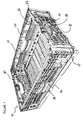
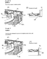
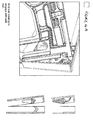
- FIG. 1 illustrates a container 10 in accordance with a first, preferred embodiment of the present invention.
- the container 10 comprises a rectangular base 12, a pair of opposed sidewalls 14 and 16, and a pair of opposed end walls 18 and 20.
- Sidewalls 14 and 16, and end walls 18 and 20, are each pivotally mounted by hinges 24, at their lower edges, to the base 12.
- Container 10 is typically formed by injection moulding from a suitable plastics material, with a pattern of openings 26 in the base 10 and walls 14 to 20 to minimize the weight of the unfilled container 10.
- a handle opening 28 is provided in a central, upper area of each side wall 14 and 16 and end wall 18 and 20, for use in carrying the container 10.
- the shape, configuration and dimensions of the container 10, including the relative proportions and thicknesses of the base 12 and walls 14 to 20 are chosen according to the design requirements.
- the base 12 and walls 14 to 20, and other parts of container 10 are typically moulded as separate parts and assembled together by snap-fit connection or otherwise.
- Container 10 is collapsible from an assembled or erect configuration, as shown in Figure 1 , in which a latching mechanism 22 secures the side walls 14, 16 and end walls 18, 20 in locking engagement, to a collapsed position (not shown) in which the end walls 18, 20 are fully folded to overlie the base 12, and the side walls 14, 16 are folded to overlie the end walls 18, 20 so that the container 10 is substantially flat.
- the latching mechanism 22 is manually operated by a user to release the end walls 18, 10 from engagement with the side walls 14, 16 so as to permit the end walls to be folded inwardly, by pivoting each end wall about its respective hinge 24 which connects to the base thereof.
- the latching mechanism 22 comprises a latching member formed as a latching bar 32 mounted substantially horizontally on an end wall 18, 20 of the container 10, and adapted so that, in an extended position, its respective ends 34, 36 are received and engaged in corresponding complementary recesses 44, 46 formed on the inner faces of the opposed sidewalls 14 and 16.
- the latching mechanism 22 further comprises a depressable button 30, associated with, and in particular integrally formed with, the latching bar 32. When the button 30 is pushed inwardly, the latching bar 32 is retracted, such that its respective ends 34, 36 are disengaged from the complementary recesses 44, 46 as described in more detail below.
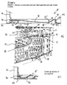
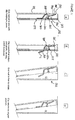
- Figure 2A, 2B and 2C show the latching mechanism 22 in a first, extended position, in which the latching mechanism provides locking engagement between the sidewalls 14, 16 and end walls 18, 20 of container 10.
- a depressable button 30 is mounted in a central aperture in an upper portion of an end wall 18, immediately above a corresponding handle opening 28.
- the latching bar 32 extends laterally from each side of button 30, and is formed integrally therewith of a resiliently deformable material.
- the button 30 has a front 30a and sides 30b, 30c which project toward the inner surface of end wall 18, and the latching bar 32 extends substantially orthogonally from the sides 30b, 30c for an initial or central portion 32'.
- the latching bar 32 is adapted to extend within end wall 18 between a plurality of abutments or projections 42, 42' formed in the end wall 18, which provides a guide path for the latching bar 32 as it moves between the extended position and a retracted position.
- the latching bar 32 is shaped with a kink 48 or deformation which conforms around a projection 42' at a location between the operating button 30 and the end 34 thereof.
- the kink 48 is adapted to slide over projection 42' to change the orientation of a section 32" of the latching bar between the central portion 32' and projection 42'.
- the section 32" of the latching bar defines an angle ⁇ to the vertical (parallel to the end wall) , as shown in Figure 2A and discussed further below.
- a biasing member 50 comprising a resiliently deformable leaf spring 52 is provided adjacent the ends 34, 36 which serves to bias the latching bar 32 in the extended position, as shown in Figure 2C .
- the spring 52 is formed from a cut-out central part of the latching bar 32, adjacent its end 34, and is curved inwardly so that it extends behind a vertically extending rib 18' on the interior surface of the end wall 18 as shown in Figure 2C . The abutment the spring 52 against of the rib 18' effects a biasing action on the latching bar 32 into the extended position.
- the leaf spring 52 holds the end 34 of latching bar 32 in engagement with the recess 44 of the end wall, to thereby securely lock together the sidewall and end wall.
- the recess may be defined by any appropriate moulded shape in the side wall, and thus may take a variety of forms, according to design requirements.
- the recess 44 may comprise a gap behind a projecting rib from the side wall that provides sufficient space to accommodate an end 34 of the latching bar 32.
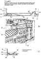
- Figure 3A, 3B and 3C show the latching mechanism 22 in a second, retracted position, in which the latching mechanism is operated to release the locking engagement between the sidewalls 14, 16 and end walls 18, 20 of container 10.
- Figure 3B shows a slightly different, non preferred, configuration for the spring 52 and end 34 of the latching bar 32.
- button 30 is depressed inwardly, as shown by arrow A, and this in turn increases the angle ⁇ , and the length of the secttion 32" of the latching bar 32 between the central portion 32' and the projection 42', as shown in Figure 3A .
- depressing button 30 pulls the latching bar 32 towards the centre of the end wall, against the biasing action of leaf spring 52 which moves further inwardly behind rib 18', so as to retract the end 34 thereof from the recess 44 in the side wall as shown in Figure 3C .
- the latching mechanism 22 is thus disengaged, and the sidewalls 14, 16 and end walls 18, 20 are released from locking engagement. This allows the container 10 to be collapsed.
- the end 34 of the latching bar 32 slides over an abutment 56 in the sidewall whilst the button 30 remains depressed, so that the end wall may be folded inwardly over the base of the container, by pivoting about lower hinge 24.
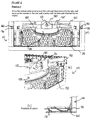
- there remains a biasing force against leaf spring 52 as shown in Figure 4C .
- the button 30 is released, as shown by arrow B.
- the latching bar 32 then returns to the extended position, under the biasing force of leaf spring 52.
- the projecting end 34 of latching bar 32 is accommodated in a large indentation 58 formed in the side wall, but is not lockingly engaged therein. It will be appreciated that the button 30 may be released whilst collapsing the end wall, once the ends of the latching bar 34, 36 are positioned for alignment with the indentation 58.
- the recess 44 is defined by a rib projecting from the internal surface of the side wall which has a generally flat configuration, no indentation 58 is required,. Instead the extended end 34 of the latching bar is accommodated inside the side wall, in front of the rib.
- the latching mechanism of the above-described embodiment is convenient to use.
- the user can simply and easily release both ends of the container simultaneously, using only one hand for each end.
- the latching bar of the first preferred embodiment is configured with a kink to allow a change of orientation of the latching bar, and thus enable its retraction and extension, it will be appreciated that other forms of connecting the button to a main portion of the latching bar, enabling corresponding movement, are possible and contemplated.
- the kink allows the latching mechanism to be formed in one piece, instead of separate components which require assembly.
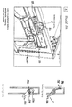
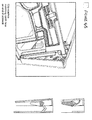
- Figures 6 to 9 show a second, preferred embodiment of the present invention, which is similar to the above-described first embodiment, but differs in the manner of operation of the latching mechanism.
- the latching mechanism is configured as an espagnolette, to allow operation of the latch by rotation.
- the latching mechanism 122 comprises a latching member formed as a latching bar 132 mounted on an end wall 118, 120 of a container 110, and adapted so that, in an extended position, its respective ends 134, 136 are received and engaged in corresponding complementary recesses 144, 146 formed on the inner faces of the opposed sidewalls 114 and 116.
- the latching mechanism 122 further comprises a rotatable lever or knob 130, associated with the latching bar 132 for effecting operation of the latching mechanism.
- lever 130 when lever 130 is rotated from a horizontal position, the latching bar 132 is retracted, such that its respective ends 134, 136 are disengaged from the complementary recesses 144, 146 in the sidewalls 114, 116 of the container 110 as described in more detail below.
- Figure 6A, 6B and 6C show the latching mechanism 122 in a first, extended position, in which the latching mechanism provides locking engagement between the sidewalls 114, 116 and end walls 118, 120 of container 110.
- a rotatable lever 130 is mounted in a central aperture in an upper portion of an end wall 118, immediately above a corresponding handle opening 128.
- the lever 130 has a central axle 131, about which it may be rotated in a clockwise or anticlockwise direction, and is shaped for gripping by hand at the underside thereof.
- a latching bar 132 extends along the length of end wall, each side of lever 130, and is pivotally connected thereto by espagnolette rods 132'.
- the lever 130, rods 132' and latching bar 132 may be formed in separate parts from the same resiliently deformable plastics material as the container, and assembled together.
- each rod 132' of the espagnolette is pivotally mounted by respective hinges 133 to the lever 130 at its proximal end and to the latching bar 132 at its distal end.
- the latching bar 132 is mounted within the interior of the end wall, in a manner that enables it to slide laterally, as described in more detail below, without significant movement in other directions.
- the latching bar is biased by a biasing member 150 comprising a resiliently deformable leaf spring 152 adjacent the ends 134, 136 of the latching bar 132, so that the ends 134, 136 are engaged in complementary recesses 144, 146 in the sidewalls of the container, as shown in Figure 6C .
- Spring 152 has a similar configuration and operation to the spring 52 of the first embodiment, and so will not be further described herein.
- the leaf spring 152 holds the ends 134, 136 of latching bar 132 in engagement with the recesses 144, 146 of the end wall, (the boundary of recesses are illustrated by dashed lines), to thereby securely lock together the end wall 118 and the sidewalls 114, 116. It will be appreciated that many other arrangements for biasing the latching bar 132 are possible.
- Figure 7A, 7B and 7C show the latching mechanism 122 in a second, retracted position, in which the latching mechanism is operated to release the locking engagement between the sidewalls 114, 116 and end walls 118, 120 of container 110.
- lever 130 is rotated about axle 131, such that the rods 132' are pivoted about their hinges 133 so that they extend at an angle ⁇ to the vertical, as shown in Figure 7A .
- the latching mechanism 132 is thus disengaged, and the sidewalls and end walls are released form locking engagement. This allows the container 110 to be collapsed.
- the end 134 of the latching bar 132 slides over the interior of in the sidewall whilst the lever 130 remains rotated, so that the end wall 118 may be folded inwardly over the base 112 of the container 110, by pivoting about its lower hinge 124. During this stage, there remains a biasing force against leaf spring, as shown in Figure 8B .
- the lever 130 may be released whilst the end wall is folded, as shown in Figures 9A and 9B .
- the lever 130 and portions 132' return to their neutral position, thus extending the latching bar 132 which is accommodated in a large indentation 158 formed in the side wall during and following collapse of the end wall 118 to overlie the base 112.
- the latching mechanism of the above-described embodiment is also convenient to use.
- the user can simply and easily release both ends of the container simultaneously, using only one hand for each end.
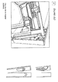
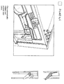
- Figures 10 to 14 show a third, preferred embodiment of the present invention, which differs from the first and second embodiments in the configuration of the latching member of the latching mechanism as well as in the manner of operation of the latching mechanism.
- the latching mechanism operates by rotational movement rather than sliding movement between engaged are released positions.
- the latching mechanism 222 comprises a latching member, which is configured as a catch 232.
- the catch comprises a clip 234, mounted on each end wall 218, 220 (not shown) of a container 210, which is configured to be engaged in complementary hooks 244 formed on the inner faces of the opposed sidewalls 214 and 216.
- the latching mechanism 222 is operated by a pivotable lever 230 located on the end wall and associated with the catch 232 located at each end of the end wall. Two possible configurations of the catch 232 of the latching mechanism 222 are described in detail below. As the skilled person will appreciate, other arrangements are possible and contemplated.
- the side walls 224, 226 have an integral flange 227 at each end thereof, which, when the container 210 is in the assembled configuration, overlaps the end walls 218, 220 by a distance sufficient to accommodate engaging parts of the catch 232 between the flange 227 and the adjacent part of the end wall, as described below.
- FIG 11 illustrates one example of a suitable catch 232 for use with the latching mechanism shown in Figure 10 .
- the catch 232 which is shown in vertical cross section along line X-X of Figure 10A in the drawings of Figure 11 , comprises a clip 234' that is pivotally mounted in the end wall 218 and a pair of complementary hooks 224 fixedly mounted on the flanges 227 of each side wall 216.
- the clip 234' extends substantially along the length of end wall 218 (although its cross section varies along its length) whilst a hook 224 is provided adjacent each end thereof behind the corresponding flanges 227 of the side walls.
- a pair of catches 232 are provided between the end wall and adjacent flange 227.
- the latching mechanism 222 is operated by a lever associated with the clip 234' to enable simultaneous release both catches, as described below.
- Clip 234' comprises a hook member 262 at respective ends of the end wall, which extends from a central portion of the clip and is configured to engage in a recess behind hook 224, an upper spring portion 264 located at either side of the centre of the end wall, and a lower lever portion 266 extending substantially along the length of the end wall.
- Clip 234' is mounted to the end wall 218 along its length by a substantially horizontally extending hinge 268 behind the hook member 262 to permit pivotal rotation about the hinge 268, and thus engagement and release of the hook member 262 from the hooks 224.
- Clip 234' is formed integrally from a resiliently deformable material, preferably the same material as the container 210.
- Figure 11A shows the position of the catch 232 when container 210 is in an assembled or erect position.
- the catch 232 is engaged so as to lock the sidewalls and end walls together.
- This is the configuration shown in Figure 10A .
- the hook member 262 of clip 234' is engaged by latching in the recess behind hook 224 on the interior surface of flange 227.
- the upper edge 270 of spring portion 264 contacts the adjacent surface 218' of end wall 218, and the lower edge of lever portion 266 extends substantially vertically, parallel to the surface of end wall 218.
- lever portion 266 which is located on either side of the centre of the end wall, is exposed by an opening 272, as best seen in Figure 10A , to allow manual operation of the lever portion 266 to disengage the catch 232.
- the lever portion 266 is exposed along substantially the full length of the end wall 218, but is conveniently operated from positions either side of the centre of the end wall, below the spring portions 264.
- Other arrangements are however possible and contemplated.
- the lever portion 266 is pulled outwardly through opening 272, as shown by arrow C, to pivot the clip 234' about hinge 268, and thereby disengage hook member 262 from hook 224.
- the rotation of the lever portion 266 may be achieved by pushing on an associated operating member located on the opposite side of the hinge 268 from the lever portion 266, as shown by arrows C in Figure 10B . Whilst the lever portion 266 is operated, the upper spring portion 264 of clip 234' is compressed against the surface of end wall 218' against its biasing force. This configuration is further illustrated in Figure 10B .
- the side walls 214, 216 and end walls 218, 220 are now released from locking engagement, allowing the end wall 218 to be folded inwardly about its lower hinge 224, and thus collapse the container 210, as shown in Figures 10C and 11C .
- the lever portion 266 may be released, as shown in Figures 10D and 11D , and the biasing force of spring portion 264 returns the clip to its initial configuration.
- the collapsed container 210 can be reassembled to the erect configuration by reversing the operation of the latching mechanism, as shown in Figures 12A to 12D , which shall not be described in detail herein. Nevertheless, it should be noted that the container 210 can be assembled without operation of the lever portion 266.
- the surface of the edge of the hook member 262 of clip 234' and the surface of the edge of the hook 224 of the catch are shaped with an angle to allow the surfaces to ride over each other when the side and end walls are brought together during assembly, as best seen in Figures 12B and 12C .
- the manual force used in erecting the walls of the container causes the automatic engagement of the clip.
- FIG 13 illustrates another example of a suitable catch 232 for use with the latching mechanism shown in Figure 10 .
- the catch 232 which is shown in vertical cross section along lines X-X (top view) and Y-Y (bottom view), comprises a clip 234" that is pivotally mounted in the end wall 218 and a pair of complementary hooks 224 fixedly mounted on the respective adjacent flanges 227 of the side walls 214, 216.
- the clip 234" extends substantially along the length of end wall 218 (although its cross section varies along its length), whilst a hook 224 is provided adjacent each end thereof behind the corresponding flanges 227 of the side walls.
- a pair of catches 232 are provided between the end wall and adjacent flange 227.
- the latching mechanism 222 is operated by a lever associated with the clip 234" on either side of the centre of each end wall to simultaneously release both catches, as described below.
- Clip 234" comprises an upper, wedge shaped portion 282 which extends substantially along the length of the end wall and is pivotable about an axis 288 opposite a curved surface 282' thereof.
- the axis 288 is defined by a horizontally extending axle that extends along at least part of the length of the clip and is connected to rotate the wedge shaped portion 282 as described herein.
- Clip 234" further comprises and a lower lever portion 286 located either side of the centre of the end wall.
- a biasing member comprising a leaf spring 284, also located on either side of the centre of the end wall, is formed above the wedge portion 282 of the clip ( Figure 13A , top view), to bias the clip in an engaged position, where the surface 282' of wedge portion 286 is received within a complementary-shaped recess of hook 224 on the flange 227, as shown in Figure 13A , bottom view.
- leaf spring 284 is formed as an over-centre spring, although other configurations for the biasing member are possible and contemplated.
- lever portion 286 is exposed by an opening 272 in the end wall, to allow manual operation of the lever portion 266 to disengage the catch 232.
- Clip 234" is formed integrally from a resiliently deformable material, preferably the same material as the container 210.
- the lever portion 286 is pulled outwardly through opening 272, as shown by arrow C, to pivot the clip 234" about axis 288, and thereby disengage wedge portion 282 from hook 224.
- the rotation of the lever portion 266 may be achieved by pushing on an associated operating member 266' located on the opposite side of the hinge 268 to the lever portion 266, instead of pulling the lever portion 286, as shown by arrows C in Figure 10B .
- the lever portion 286 Whilst the lever portion 286 is operated, the upper spring portion 284 of clip 234" is deformed against its biasing force, to "over-centre” the spring, and thus reverse its arcuate shape so that it is compressed against the inner surface 218' of the end wall 218, as shown in Figure 13B .
- the side walls and end walls are now released from locking engagement, allowing the end wall 218 to be folded inwardly about its lower hinge, and thus collapse the container 210, as shown in Figures 10C and 11C .
- the lever portion 286 may be released, whereby the over-centre spring 284 returns to its original shape and biases the clip back to its initial configuration, as shown in Figures 10D and 13D .
- the collapsed container 210 can be reassembled to the erect configuration by reversing the operation of the latching mechanism, as shown in Figures 14A to 14D , which shall not be described in detail herein. Nevertheless, it should be noted that the container 210 can be assembled without operation of the lever portion 286.
- the curved surface of wedge portion 282 of clip 234' and the surface of the edge of the hook 224 of the catch are shaped with an angle to allow the surfaces to ride over each other when the side and end walls are brought together during assembly, as best seen in Figures 14B and 14C .
- the manual force used in erecting the walls of the container causes the automatic engagement of the clip.
- the latching mechanism of the embodiment of Figure 10 is convenient to use.
- the user can simply and easily release both ends of the container simultaneously, using only one hand for each end.
- biasing means can take any appropriate form suitable for biasing the latch in an engaged or disengaged position.
- actuator can take different forms from those described, where appropriate.
- features of each embodiment can be used in combination with features of the other embodiments, or with other known configurations. It is intended to include all such variations, modifications and equivalents which fall within the scope of the present invention.
Landscapes
- Engineering & Computer Science (AREA)
- Mechanical Engineering (AREA)
- Rigid Containers With Two Or More Constituent Elements (AREA)
Priority Applications (2)
| Application Number | Priority Date | Filing Date | Title |
|---|---|---|---|
| EP10171140.6A EP2338803B8 (de) | 2007-09-13 | 2008-09-15 | Zusammenklappbarer Behälter |
| DE200820017658 DE202008017658U1 (de) | 2007-09-13 | 2008-09-15 | Zusammenklappbarer Behälter |
Applications Claiming Priority (1)
| Application Number | Priority Date | Filing Date | Title |
|---|---|---|---|
| GB0717892A GB2452750B (en) | 2007-09-13 | 2007-09-13 | Container |
Related Child Applications (2)
| Application Number | Title | Priority Date | Filing Date |
|---|---|---|---|
| EP10171140.6A Division EP2338803B8 (de) | 2007-09-13 | 2008-09-15 | Zusammenklappbarer Behälter |
| EP10171140.6A Division-Into EP2338803B8 (de) | 2007-09-13 | 2008-09-15 | Zusammenklappbarer Behälter |
Publications (2)
| Publication Number | Publication Date |
|---|---|
| EP2036825A1 true EP2036825A1 (de) | 2009-03-18 |
| EP2036825B1 EP2036825B1 (de) | 2016-09-14 |
Family
ID=38658920
Family Applications (2)
| Application Number | Title | Priority Date | Filing Date |
|---|---|---|---|
| EP08253028.8A Revoked EP2036825B1 (de) | 2007-09-13 | 2008-09-15 | Zusammenklappbarer Behälter |
| EP10171140.6A Not-in-force EP2338803B8 (de) | 2007-09-13 | 2008-09-15 | Zusammenklappbarer Behälter |
Family Applications After (1)
| Application Number | Title | Priority Date | Filing Date |
|---|---|---|---|
| EP10171140.6A Not-in-force EP2338803B8 (de) | 2007-09-13 | 2008-09-15 | Zusammenklappbarer Behälter |
Country Status (4)
| Country | Link |
|---|---|
| EP (2) | EP2036825B1 (de) |
| DE (1) | DE202008017658U1 (de) |
| ES (2) | ES2606403T3 (de) |
| GB (1) | GB2452750B (de) |
Cited By (14)
| Publication number | Priority date | Publication date | Assignee | Title |
|---|---|---|---|---|
| DE202009015184U1 (de) | 2009-11-09 | 2010-03-25 | bekuplast Kunststoffverarbeitungs-Gesellschaft mit beschränkter Haftung | Transport- und Lagerbehälter mit Riegeleinrichtung |
| DE202010005898U1 (de) | 2010-04-20 | 2010-08-05 | Aldi Einkauf Gmbh & Co. Ohg | Transport- und/oder Lagerbehälter |
| WO2010119073A1 (de) * | 2009-04-15 | 2010-10-21 | Ifco Systems Gmbh | Kiste mit faltbaren seitenwänden und verriegelungsmechanismen mit überlastschutz |
| WO2010118758A1 (de) * | 2009-04-15 | 2010-10-21 | Ifco Systems Gmbh | Behälter mit klappbarer seitenwand |
| EP2256049A1 (de) | 2009-05-28 | 2010-12-01 | Aldi Einkauf GmbH & Co. oHG | Transport- und/oder Lagerbehälter |
| DE102009023069A1 (de) * | 2009-05-28 | 2010-12-02 | Aldi Einkauf Gmbh & Co. Ohg | Transport- und/oder Lagerbehälter |
| WO2010146190A1 (es) * | 2009-06-15 | 2010-12-23 | Sp Berner Plastic Group, S.L. | Caja plegable |
| WO2012107086A1 (de) * | 2011-02-10 | 2012-08-16 | Ifco Systems Gmbh | Kiste |
| EP2647580A1 (de) | 2009-02-12 | 2013-10-09 | Leisch Beratungs- Und Beteiligungs-GmbH | Klappbox |
| US8651310B2 (en) | 2009-04-15 | 2014-02-18 | Ifco Systems Gmbh | Box having foldable and dismantlable exterior walls |
| US8662333B2 (en) | 2009-04-15 | 2014-03-04 | Ifco Systems Gmbh | Box having foldable sidewalls with a stable sidewall structure |
| US8807365B2 (en) | 2009-04-15 | 2014-08-19 | Ifco Systems Gmbh | Box having foldable and self-locking side walls |
| EP3360813A1 (de) * | 2017-02-10 | 2018-08-15 | ALDI SÜD Dienstleistungs-GmbH & Co. oHG | Transport- und/oder lagerbehälter |
| US10065763B2 (en) | 2016-09-15 | 2018-09-04 | Arena Packaging, Llc | Wall latching system |
Families Citing this family (5)
| Publication number | Priority date | Publication date | Assignee | Title |
|---|---|---|---|---|
| DE102008060913A1 (de) * | 2008-02-11 | 2009-08-13 | Fritz Schäfer GmbH | Vorrichtung zum Entriegeln von klappbaren Seitenwänden von Kästen bzw. Behältern |
| DE202009007608U1 (de) | 2009-05-28 | 2009-08-06 | Walther Faltsysteme Gmbh | Transport- und/oder Lagerbehälter |
| DE102012017295A1 (de) * | 2012-08-31 | 2014-03-06 | Bb-Stanz- Und Umformtechnik Gmbh | Verriegelung für Klappe |
| CN104691892B (zh) | 2015-01-16 | 2017-07-28 | 上海鸿研物流技术有限公司 | 折叠箱 |
| RU194604U1 (ru) * | 2019-07-29 | 2019-12-17 | Общество с ограниченной ответственностью "Ай-Пласт" | Складной контейнер |
Citations (8)
| Publication number | Priority date | Publication date | Assignee | Title |
|---|---|---|---|---|
| GB710088A (en) | 1950-11-14 | 1954-06-09 | Jardine John Ltd | Improvements relating to typewriters |
| WO2000068099A1 (en) * | 1999-05-10 | 2000-11-16 | Schoeller Wavin Systems N.V. | Container with lockable side walls |
| CA2309234A1 (en) * | 1999-05-31 | 2000-11-30 | Thomas Gabriel Bela Merey | Foldable container |
| US20040178197A1 (en) * | 2003-03-10 | 2004-09-16 | Rehrig Pacific Company | Collapsible container |
| US20050098556A1 (en) * | 2002-01-03 | 2005-05-12 | Richard Kellerer | Collapsible container comprising a container base and four collapsible lateral walls |
| EP1655232A1 (de) * | 2003-08-13 | 2006-05-10 | Mitsubishi Plastics Inc. | Faltbehälter |
| EP1746036A1 (de) * | 2005-07-19 | 2007-01-24 | Odesa Gelistirilmis Polimer Yatirimlari Ve Dis Tic | Verriegelungssystem für einen zusammenklappbaren Kasten |
| EP1785360B1 (de) | 2005-11-02 | 2009-01-14 | Linpac Allibert Limited | Zusammenklappbarer Behälter |
Family Cites Families (6)
| Publication number | Priority date | Publication date | Assignee | Title |
|---|---|---|---|---|
| CA2273556A1 (en) * | 1999-05-31 | 2000-11-30 | Thomas Gabriel Bela Merey | Foldable container |
| CA2330996C (en) * | 2001-01-15 | 2007-08-21 | Norseman Plastics Limited | Biased latch hinge |
| JP4083508B2 (ja) | 2002-08-29 | 2008-04-30 | 三甲株式会社 | 折り畳みコンテナー |
| EP1544116B1 (de) * | 2003-12-15 | 2009-07-15 | Arca Systems AB | Verriegelungssystem für einen zusammenlegbaren Behälter |
| SE527894C2 (sv) | 2004-04-23 | 2006-07-04 | Arca Systems Internat Ab | Låssystem för en behållare och en behållare med ett sådant låssystem |
| DE102007052916A1 (de) * | 2007-08-20 | 2009-02-26 | Odesa Gelistirilmis Polimer Yatirimlari Ve Dis Ticaret A.S. | Gleitverriegelungsvorrichtung für zusammenklappbare Kisten |
-
2007
- 2007-09-13 GB GB0717892A patent/GB2452750B/en not_active Expired - Fee Related
-
2008
- 2008-09-15 ES ES08253028.8T patent/ES2606403T3/es active Active
- 2008-09-15 ES ES10171140.6T patent/ES2692330T3/es active Active
- 2008-09-15 EP EP08253028.8A patent/EP2036825B1/de not_active Revoked
- 2008-09-15 DE DE200820017658 patent/DE202008017658U1/de not_active Expired - Lifetime
- 2008-09-15 EP EP10171140.6A patent/EP2338803B8/de not_active Not-in-force
Patent Citations (8)
| Publication number | Priority date | Publication date | Assignee | Title |
|---|---|---|---|---|
| GB710088A (en) | 1950-11-14 | 1954-06-09 | Jardine John Ltd | Improvements relating to typewriters |
| WO2000068099A1 (en) * | 1999-05-10 | 2000-11-16 | Schoeller Wavin Systems N.V. | Container with lockable side walls |
| CA2309234A1 (en) * | 1999-05-31 | 2000-11-30 | Thomas Gabriel Bela Merey | Foldable container |
| US20050098556A1 (en) * | 2002-01-03 | 2005-05-12 | Richard Kellerer | Collapsible container comprising a container base and four collapsible lateral walls |
| US20040178197A1 (en) * | 2003-03-10 | 2004-09-16 | Rehrig Pacific Company | Collapsible container |
| EP1655232A1 (de) * | 2003-08-13 | 2006-05-10 | Mitsubishi Plastics Inc. | Faltbehälter |
| EP1746036A1 (de) * | 2005-07-19 | 2007-01-24 | Odesa Gelistirilmis Polimer Yatirimlari Ve Dis Tic | Verriegelungssystem für einen zusammenklappbaren Kasten |
| EP1785360B1 (de) | 2005-11-02 | 2009-01-14 | Linpac Allibert Limited | Zusammenklappbarer Behälter |
Cited By (29)
| Publication number | Priority date | Publication date | Assignee | Title |
|---|---|---|---|---|
| EP2647580A1 (de) | 2009-02-12 | 2013-10-09 | Leisch Beratungs- Und Beteiligungs-GmbH | Klappbox |
| EP2396232B2 (de) † | 2009-02-12 | 2017-01-18 | Leisch Beratungs- Und Beteiligungs-GmbH | Klappbox |
| US8651310B2 (en) | 2009-04-15 | 2014-02-18 | Ifco Systems Gmbh | Box having foldable and dismantlable exterior walls |
| US8627973B2 (en) | 2009-04-15 | 2014-01-14 | Ifco Systems Gmbh | Container comprising a collapsible sidewall |
| US8640912B2 (en) | 2009-04-15 | 2014-02-04 | Ifco Systems Gmbh | Box with foldable sidewalls and locking mechanisms with overload protection |
| WO2010119073A1 (de) * | 2009-04-15 | 2010-10-21 | Ifco Systems Gmbh | Kiste mit faltbaren seitenwänden und verriegelungsmechanismen mit überlastschutz |
| CN102395513B (zh) * | 2009-04-15 | 2015-03-25 | 埃弗科系统有限责任公司 | 具有可折叠的侧壁的容器 |
| US8875924B2 (en) | 2009-04-15 | 2014-11-04 | Ifco Systems Gmbh | Box with foldable sidewalls and locking mechanisms with overload protection |
| US8807365B2 (en) | 2009-04-15 | 2014-08-19 | Ifco Systems Gmbh | Box having foldable and self-locking side walls |
| CN102459012B (zh) * | 2009-04-15 | 2014-02-12 | 埃弗科系统有限责任公司 | 具有可折叠的侧壁和带过载保护的锁定机构的箱子 |
| US8662333B2 (en) | 2009-04-15 | 2014-03-04 | Ifco Systems Gmbh | Box having foldable sidewalls with a stable sidewall structure |
| CN102459012A (zh) * | 2009-04-15 | 2012-05-16 | 埃弗科系统有限责任公司 | 具有可折叠的侧壁和带过载保护的锁定机构的箱子 |
| WO2010118758A1 (de) * | 2009-04-15 | 2010-10-21 | Ifco Systems Gmbh | Behälter mit klappbarer seitenwand |
| DE102009023069B4 (de) * | 2009-05-28 | 2011-07-14 | Aldi Einkauf GmbH & Co. oHG, 45476 | Transport- und/oder Lagerbehälter |
| DE102009023069A1 (de) * | 2009-05-28 | 2010-12-02 | Aldi Einkauf Gmbh & Co. Ohg | Transport- und/oder Lagerbehälter |
| EP2256049A1 (de) | 2009-05-28 | 2010-12-01 | Aldi Einkauf GmbH & Co. oHG | Transport- und/oder Lagerbehälter |
| ES2350791A1 (es) * | 2009-06-15 | 2011-01-27 | Sp Berner Plastic Group, S.L. | Caja plegable. |
| US8584883B2 (en) | 2009-06-15 | 2013-11-19 | Sp Berner Plastic Group, S.L. | Collapsible box |
| CN102459014A (zh) * | 2009-06-15 | 2012-05-16 | Sp伯纳塑胶集团有限公司 | 可折叠盒子 |
| CN102459014B (zh) * | 2009-06-15 | 2014-07-23 | Sp伯纳塑胶集团有限公司 | 可折叠盒子 |
| WO2010146190A1 (es) * | 2009-06-15 | 2010-12-23 | Sp Berner Plastic Group, S.L. | Caja plegable |
| WO2011054707A1 (de) | 2009-11-09 | 2011-05-12 | Bekuplast Kunststoffverarbeitungs-Gmbh | Transport- und lagerbehälter mit riegeleinrichtung |
| DE202009015184U1 (de) | 2009-11-09 | 2010-03-25 | bekuplast Kunststoffverarbeitungs-Gesellschaft mit beschränkter Haftung | Transport- und Lagerbehälter mit Riegeleinrichtung |
| EP2380815A1 (de) | 2010-04-20 | 2011-10-26 | Aldi Einkauf GmbH & Co. oHG | Transport- und/oder Lagerbehälter |
| DE202010005898U1 (de) | 2010-04-20 | 2010-08-05 | Aldi Einkauf Gmbh & Co. Ohg | Transport- und/oder Lagerbehälter |
| WO2012107086A1 (de) * | 2011-02-10 | 2012-08-16 | Ifco Systems Gmbh | Kiste |
| US9796525B2 (en) | 2011-02-10 | 2017-10-24 | Ifco Systems Gmbh | Box |
| US10065763B2 (en) | 2016-09-15 | 2018-09-04 | Arena Packaging, Llc | Wall latching system |
| EP3360813A1 (de) * | 2017-02-10 | 2018-08-15 | ALDI SÜD Dienstleistungs-GmbH & Co. oHG | Transport- und/oder lagerbehälter |
Also Published As
| Publication number | Publication date |
|---|---|
| GB2452750A (en) | 2009-03-18 |
| GB0717892D0 (en) | 2007-10-24 |
| GB2452750B (en) | 2012-06-20 |
| ES2692330T3 (es) | 2018-12-03 |
| EP2338803A1 (de) | 2011-06-29 |
| DE202008017658U1 (de) | 2010-07-22 |
| EP2338803B8 (de) | 2018-10-24 |
| EP2338803B1 (de) | 2018-07-25 |
| ES2606403T3 (es) | 2017-03-23 |
| EP2036825B1 (de) | 2016-09-14 |
Similar Documents
| Publication | Publication Date | Title |
|---|---|---|
| EP2036825A1 (de) | Zusammenklappbarer Behälter | |
| CA2327942C (en) | Collapsible container | |
| US6290081B1 (en) | Foldable container | |
| US6073790A (en) | Folding container with releasably locking side walls | |
| US7311220B2 (en) | Collapsible container comprising a container base and four collapsible lateral walls | |
| EP2133180B1 (de) | Werkzeugbehälteranordnung | |
| US7322110B2 (en) | Knife with trigger actuator for retractable blade | |
| EP0911268B1 (de) | Zusammenlegbarer Behälter | |
| CN107073700B (zh) | 锯架 | |
| EP1744961A1 (de) | Mit einem griff versehenes verriegelungssystem für den einsatz in einem container | |
| CZ290012B6 (cs) | Skládací přepravka s uvolnitelně blokovatelnými bočními stěnami | |
| PL201026B1 (pl) | Pojemnik, zwłaszcza pojemnik wielokrotnegu użytku, ze składanymi ściankami bocznymi | |
| WO2000068099A1 (en) | Container with lockable side walls | |
| US20180207788A1 (en) | Adjustable sawhorse | |
| US20150322717A1 (en) | Folding step stool | |
| US6443074B1 (en) | Folding table | |
| US9422087B1 (en) | Foldable crate and locking mechanisms therefor | |
| CA2309234A1 (en) | Foldable container | |
| AU2003235566A1 (en) | A Handle | |
| US20070084358A1 (en) | Refuse bin including a compacting mechanism | |
| EP2354025A2 (de) | Behälter | |
| CA2715583A1 (en) | Container with a retractable handle | |
| US6666151B2 (en) | Folding table | |
| EP1544116A1 (de) | Verriegelungssystem für einen zusammenlegbaren Behälter | |
| TWI749190B (zh) | 曲柄把手總成 |
Legal Events
| Date | Code | Title | Description |
|---|---|---|---|
| PUAI | Public reference made under article 153(3) epc to a published international application that has entered the european phase |
Free format text: ORIGINAL CODE: 0009012 |
|
| AK | Designated contracting states |
Kind code of ref document: A1 Designated state(s): AT BE BG CH CY CZ DE DK EE ES FI FR GB GR HR HU IE IS IT LI LT LU LV MC MT NL NO PL PT RO SE SI SK TR |
|
| AX | Request for extension of the european patent |
Extension state: AL BA MK RS |
|
| 17P | Request for examination filed |
Effective date: 20090917 |
|
| AKX | Designation fees paid |
Designated state(s): AT BE BG CH CY CZ DE DK EE ES FI FR GB GR HR HU IE IS IT LI LT LU LV MC MT NL NO PL PT RO SE SI SK TR |
|
| 17Q | First examination report despatched |
Effective date: 20100223 |
|
| TPAC | Observations filed by third parties |
Free format text: ORIGINAL CODE: EPIDOSNTIPA |
|
| TPAC | Observations filed by third parties |
Free format text: ORIGINAL CODE: EPIDOSNTIPA |
|
| TPAC | Observations filed by third parties |
Free format text: ORIGINAL CODE: EPIDOSNTIPA |
|
| GRAP | Despatch of communication of intention to grant a patent |
Free format text: ORIGINAL CODE: EPIDOSNIGR1 |
|
| INTG | Intention to grant announced |
Effective date: 20160318 |
|
| INTG | Intention to grant announced |
Effective date: 20160322 |
|
| GRAS | Grant fee paid |
Free format text: ORIGINAL CODE: EPIDOSNIGR3 |
|
| GRAA | (expected) grant |
Free format text: ORIGINAL CODE: 0009210 |
|
| AK | Designated contracting states |
Kind code of ref document: B1 Designated state(s): AT BE BG CH CY CZ DE DK EE ES FI FR GB GR HR HU IE IS IT LI LT LU LV MC MT NL NO PL PT RO SE SI SK TR |
|
| REG | Reference to a national code |
Ref country code: GB Ref legal event code: FG4D |
|
| REG | Reference to a national code |
Ref country code: CH Ref legal event code: EP |
|
| REG | Reference to a national code |
Ref country code: IE Ref legal event code: FG4D |
|
| REG | Reference to a national code |
Ref country code: AT Ref legal event code: REF Ref document number: 828687 Country of ref document: AT Kind code of ref document: T Effective date: 20161015 |
|
| REG | Reference to a national code |
Ref country code: DE Ref legal event code: R096 Ref document number: 602008046267 Country of ref document: DE Ref country code: FR Ref legal event code: PLFP Year of fee payment: 9 |
|
| REG | Reference to a national code |
Ref country code: LT Ref legal event code: MG4D |
|
| REG | Reference to a national code |
Ref country code: NL Ref legal event code: MP Effective date: 20160914 |
|
| REG | Reference to a national code |
Ref country code: DE Ref legal event code: R026 Ref document number: 602008046267 Country of ref document: DE |
|
| PG25 | Lapsed in a contracting state [announced via postgrant information from national office to epo] |
Ref country code: NO Free format text: LAPSE BECAUSE OF FAILURE TO SUBMIT A TRANSLATION OF THE DESCRIPTION OR TO PAY THE FEE WITHIN THE PRESCRIBED TIME-LIMIT Effective date: 20161214 Ref country code: FI Free format text: LAPSE BECAUSE OF FAILURE TO SUBMIT A TRANSLATION OF THE DESCRIPTION OR TO PAY THE FEE WITHIN THE PRESCRIBED TIME-LIMIT Effective date: 20160914 Ref country code: LT Free format text: LAPSE BECAUSE OF FAILURE TO SUBMIT A TRANSLATION OF THE DESCRIPTION OR TO PAY THE FEE WITHIN THE PRESCRIBED TIME-LIMIT Effective date: 20160914 Ref country code: HR Free format text: LAPSE BECAUSE OF FAILURE TO SUBMIT A TRANSLATION OF THE DESCRIPTION OR TO PAY THE FEE WITHIN THE PRESCRIBED TIME-LIMIT Effective date: 20160914 |
|
| PLBI | Opposition filed |
Free format text: ORIGINAL CODE: 0009260 |
|
| REG | Reference to a national code |
Ref country code: AT Ref legal event code: MK05 Ref document number: 828687 Country of ref document: AT Kind code of ref document: T Effective date: 20160914 |
|
| PG25 | Lapsed in a contracting state [announced via postgrant information from national office to epo] |
Ref country code: GR Free format text: LAPSE BECAUSE OF FAILURE TO SUBMIT A TRANSLATION OF THE DESCRIPTION OR TO PAY THE FEE WITHIN THE PRESCRIBED TIME-LIMIT Effective date: 20161215 Ref country code: BE Free format text: LAPSE BECAUSE OF NON-PAYMENT OF DUE FEES Effective date: 20160930 Ref country code: SE Free format text: LAPSE BECAUSE OF FAILURE TO SUBMIT A TRANSLATION OF THE DESCRIPTION OR TO PAY THE FEE WITHIN THE PRESCRIBED TIME-LIMIT Effective date: 20160914 Ref country code: NL Free format text: LAPSE BECAUSE OF FAILURE TO SUBMIT A TRANSLATION OF THE DESCRIPTION OR TO PAY THE FEE WITHIN THE PRESCRIBED TIME-LIMIT Effective date: 20160914 Ref country code: LV Free format text: LAPSE BECAUSE OF FAILURE TO SUBMIT A TRANSLATION OF THE DESCRIPTION OR TO PAY THE FEE WITHIN THE PRESCRIBED TIME-LIMIT Effective date: 20160914 |
|
| 26 | Opposition filed |
Opponent name: ALDI SUED DIENSTLEISTUNGS-GMBH & CO. OHG Effective date: 20170119 |
|
| PLBI | Opposition filed |
Free format text: ORIGINAL CODE: 0009260 |
|
| PG25 | Lapsed in a contracting state [announced via postgrant information from national office to epo] |
Ref country code: EE Free format text: LAPSE BECAUSE OF FAILURE TO SUBMIT A TRANSLATION OF THE DESCRIPTION OR TO PAY THE FEE WITHIN THE PRESCRIBED TIME-LIMIT Effective date: 20160914 Ref country code: RO Free format text: LAPSE BECAUSE OF FAILURE TO SUBMIT A TRANSLATION OF THE DESCRIPTION OR TO PAY THE FEE WITHIN THE PRESCRIBED TIME-LIMIT Effective date: 20160914 |
|
| REG | Reference to a national code |
Ref country code: CH Ref legal event code: PL |
|
| 26 | Opposition filed |
Opponent name: WALTHER FALTSYSTEME GMBH Effective date: 20170403 |
|
| PG25 | Lapsed in a contracting state [announced via postgrant information from national office to epo] |
Ref country code: CZ Free format text: LAPSE BECAUSE OF FAILURE TO SUBMIT A TRANSLATION OF THE DESCRIPTION OR TO PAY THE FEE WITHIN THE PRESCRIBED TIME-LIMIT Effective date: 20160914 Ref country code: SK Free format text: LAPSE BECAUSE OF FAILURE TO SUBMIT A TRANSLATION OF THE DESCRIPTION OR TO PAY THE FEE WITHIN THE PRESCRIBED TIME-LIMIT Effective date: 20160914 Ref country code: PL Free format text: LAPSE BECAUSE OF FAILURE TO SUBMIT A TRANSLATION OF THE DESCRIPTION OR TO PAY THE FEE WITHIN THE PRESCRIBED TIME-LIMIT Effective date: 20160914 Ref country code: AT Free format text: LAPSE BECAUSE OF FAILURE TO SUBMIT A TRANSLATION OF THE DESCRIPTION OR TO PAY THE FEE WITHIN THE PRESCRIBED TIME-LIMIT Effective date: 20160914 Ref country code: BE Free format text: LAPSE BECAUSE OF FAILURE TO SUBMIT A TRANSLATION OF THE DESCRIPTION OR TO PAY THE FEE WITHIN THE PRESCRIBED TIME-LIMIT Effective date: 20160914 Ref country code: BG Free format text: LAPSE BECAUSE OF FAILURE TO SUBMIT A TRANSLATION OF THE DESCRIPTION OR TO PAY THE FEE WITHIN THE PRESCRIBED TIME-LIMIT Effective date: 20161214 Ref country code: PT Free format text: LAPSE BECAUSE OF FAILURE TO SUBMIT A TRANSLATION OF THE DESCRIPTION OR TO PAY THE FEE WITHIN THE PRESCRIBED TIME-LIMIT Effective date: 20170116 Ref country code: IS Free format text: LAPSE BECAUSE OF FAILURE TO SUBMIT A TRANSLATION OF THE DESCRIPTION OR TO PAY THE FEE WITHIN THE PRESCRIBED TIME-LIMIT Effective date: 20170114 |
|
| REG | Reference to a national code |
Ref country code: GB Ref legal event code: 732E Free format text: REGISTERED BETWEEN 20170511 AND 20170517 |
|
| REG | Reference to a national code |
Ref country code: IE Ref legal event code: MM4A |
|
| PG25 | Lapsed in a contracting state [announced via postgrant information from national office to epo] |
Ref country code: IT Free format text: LAPSE BECAUSE OF FAILURE TO SUBMIT A TRANSLATION OF THE DESCRIPTION OR TO PAY THE FEE WITHIN THE PRESCRIBED TIME-LIMIT Effective date: 20160914 |
|
| PLAX | Notice of opposition and request to file observation + time limit sent |
Free format text: ORIGINAL CODE: EPIDOSNOBS2 |
|
| PG25 | Lapsed in a contracting state [announced via postgrant information from national office to epo] |
Ref country code: DK Free format text: LAPSE BECAUSE OF FAILURE TO SUBMIT A TRANSLATION OF THE DESCRIPTION OR TO PAY THE FEE WITHIN THE PRESCRIBED TIME-LIMIT Effective date: 20160914 Ref country code: CH Free format text: LAPSE BECAUSE OF NON-PAYMENT OF DUE FEES Effective date: 20160930 Ref country code: IE Free format text: LAPSE BECAUSE OF NON-PAYMENT OF DUE FEES Effective date: 20160915 Ref country code: LI Free format text: LAPSE BECAUSE OF NON-PAYMENT OF DUE FEES Effective date: 20160930 |
|
| PG25 | Lapsed in a contracting state [announced via postgrant information from national office to epo] |
Ref country code: LU Free format text: LAPSE BECAUSE OF NON-PAYMENT OF DUE FEES Effective date: 20160915 |
|
| REG | Reference to a national code |
Ref country code: FR Ref legal event code: PLFP Year of fee payment: 10 |
|
| PG25 | Lapsed in a contracting state [announced via postgrant information from national office to epo] |
Ref country code: SI Free format text: LAPSE BECAUSE OF FAILURE TO SUBMIT A TRANSLATION OF THE DESCRIPTION OR TO PAY THE FEE WITHIN THE PRESCRIBED TIME-LIMIT Effective date: 20160914 |
|
| PLBB | Reply of patent proprietor to notice(s) of opposition received |
Free format text: ORIGINAL CODE: EPIDOSNOBS3 |
|
| PLAY | Examination report in opposition despatched + time limit |
Free format text: ORIGINAL CODE: EPIDOSNORE2 |
|
| PG25 | Lapsed in a contracting state [announced via postgrant information from national office to epo] |
Ref country code: CY Free format text: LAPSE BECAUSE OF FAILURE TO SUBMIT A TRANSLATION OF THE DESCRIPTION OR TO PAY THE FEE WITHIN THE PRESCRIBED TIME-LIMIT Effective date: 20160914 Ref country code: HU Free format text: LAPSE BECAUSE OF FAILURE TO SUBMIT A TRANSLATION OF THE DESCRIPTION OR TO PAY THE FEE WITHIN THE PRESCRIBED TIME-LIMIT; INVALID AB INITIO Effective date: 20080915 |
|
| PG25 | Lapsed in a contracting state [announced via postgrant information from national office to epo] |
Ref country code: TR Free format text: LAPSE BECAUSE OF FAILURE TO SUBMIT A TRANSLATION OF THE DESCRIPTION OR TO PAY THE FEE WITHIN THE PRESCRIBED TIME-LIMIT Effective date: 20160914 Ref country code: MC Free format text: LAPSE BECAUSE OF FAILURE TO SUBMIT A TRANSLATION OF THE DESCRIPTION OR TO PAY THE FEE WITHIN THE PRESCRIBED TIME-LIMIT Effective date: 20160914 Ref country code: MT Free format text: LAPSE BECAUSE OF NON-PAYMENT OF DUE FEES Effective date: 20160930 |
|
| PLBC | Reply to examination report in opposition received |
Free format text: ORIGINAL CODE: EPIDOSNORE3 |
|
| REG | Reference to a national code |
Ref country code: FR Ref legal event code: PLFP Year of fee payment: 11 |
|
| PGFP | Annual fee paid to national office [announced via postgrant information from national office to epo] |
Ref country code: FR Payment date: 20190924 Year of fee payment: 12 Ref country code: DE Payment date: 20190823 Year of fee payment: 12 |
|
| PGFP | Annual fee paid to national office [announced via postgrant information from national office to epo] |
Ref country code: GB Payment date: 20190924 Year of fee payment: 12 |
|
| REG | Reference to a national code |
Ref country code: DE Ref legal event code: R064 Ref document number: 602008046267 Country of ref document: DE Ref country code: DE Ref legal event code: R103 Ref document number: 602008046267 Country of ref document: DE |
|
| PGFP | Annual fee paid to national office [announced via postgrant information from national office to epo] |
Ref country code: ES Payment date: 20191023 Year of fee payment: 12 |
|
| RDAF | Communication despatched that patent is revoked |
Free format text: ORIGINAL CODE: EPIDOSNREV1 |
|
| STAA | Information on the status of an ep patent application or granted ep patent |
Free format text: STATUS: THE PATENT HAS BEEN GRANTED |
|
| RDAG | Patent revoked |
Free format text: ORIGINAL CODE: 0009271 |
|
| STAA | Information on the status of an ep patent application or granted ep patent |
Free format text: STATUS: PATENT REVOKED |
|
| REG | Reference to a national code |
Ref country code: FI Ref legal event code: MGE |
|
| 27W | Patent revoked |
Effective date: 20200123 |
|
| GBPR | Gb: patent revoked under art. 102 of the ep convention designating the uk as contracting state |
Effective date: 20200123 |