EP2034655A2 - Systeme und Verfahren für Übertragung und Empfang von Daten einschließlich Verarbeitungs- und Pufferungsfunktionen - Google Patents
Systeme und Verfahren für Übertragung und Empfang von Daten einschließlich Verarbeitungs- und Pufferungsfunktionen Download PDFInfo
- Publication number
- EP2034655A2 EP2034655A2 EP08251764A EP08251764A EP2034655A2 EP 2034655 A2 EP2034655 A2 EP 2034655A2 EP 08251764 A EP08251764 A EP 08251764A EP 08251764 A EP08251764 A EP 08251764A EP 2034655 A2 EP2034655 A2 EP 2034655A2
- Authority
- EP
- European Patent Office
- Prior art keywords
- buffer
- data
- receiver
- level
- packets
- Prior art date
- Legal status (The legal status is an assumption and is not a legal conclusion. Google has not performed a legal analysis and makes no representation as to the accuracy of the status listed.)
- Withdrawn
Links
- 230000005540 biological transmission Effects 0.000 title claims abstract description 63
- 238000000034 method Methods 0.000 title description 35
- 238000012545 processing Methods 0.000 title description 9
- 230000003139 buffering effect Effects 0.000 title description 6
- 239000000872 buffer Substances 0.000 claims abstract description 158
- 239000003990 capacitor Substances 0.000 claims description 3
- 230000003247 decreasing effect Effects 0.000 claims description 3
- 230000008878 coupling Effects 0.000 claims 3
- 238000010168 coupling process Methods 0.000 claims 3
- 238000005859 coupling reaction Methods 0.000 claims 3
- 230000008859 change Effects 0.000 description 18
- 238000010586 diagram Methods 0.000 description 18
- 230000006870 function Effects 0.000 description 12
- 238000004891 communication Methods 0.000 description 9
- 230000008569 process Effects 0.000 description 9
- 238000011084 recovery Methods 0.000 description 7
- 230000008901 benefit Effects 0.000 description 6
- 230000005236 sound signal Effects 0.000 description 5
- 238000004590 computer program Methods 0.000 description 4
- 230000007423 decrease Effects 0.000 description 4
- 230000000977 initiatory effect Effects 0.000 description 4
- 238000012937 correction Methods 0.000 description 3
- 230000007246 mechanism Effects 0.000 description 3
- 238000012546 transfer Methods 0.000 description 3
- 238000013461 design Methods 0.000 description 2
- 238000004519 manufacturing process Methods 0.000 description 2
- 230000003321 amplification Effects 0.000 description 1
- 238000009429 electrical wiring Methods 0.000 description 1
- 238000005562 fading Methods 0.000 description 1
- 238000005259 measurement Methods 0.000 description 1
- 238000003199 nucleic acid amplification method Methods 0.000 description 1
- 230000000644 propagated effect Effects 0.000 description 1
- 230000007704 transition Effects 0.000 description 1
Images




Classifications
-
- H—ELECTRICITY
- H04—ELECTRIC COMMUNICATION TECHNIQUE
- H04W—WIRELESS COMMUNICATION NETWORKS
- H04W28/00—Network traffic management; Network resource management
- H04W28/02—Traffic management, e.g. flow control or congestion control
- H04W28/10—Flow control between communication endpoints
- H04W28/14—Flow control between communication endpoints using intermediate storage
-
- H—ELECTRICITY
- H04—ELECTRIC COMMUNICATION TECHNIQUE
- H04J—MULTIPLEX COMMUNICATION
- H04J3/00—Time-division multiplex systems
- H04J3/02—Details
- H04J3/06—Synchronising arrangements
- H04J3/062—Synchronisation of signals having the same nominal but fluctuating bit rates, e.g. using buffers
- H04J3/0632—Synchronisation of packets and cells, e.g. transmission of voice via a packet network, circuit emulation service [CES]
-
- H—ELECTRICITY
- H04—ELECTRIC COMMUNICATION TECHNIQUE
- H04J—MULTIPLEX COMMUNICATION
- H04J3/00—Time-division multiplex systems
- H04J3/02—Details
- H04J3/12—Arrangements providing for calling or supervisory signals
-
- H—ELECTRICITY
- H04—ELECTRIC COMMUNICATION TECHNIQUE
- H04L—TRANSMISSION OF DIGITAL INFORMATION, e.g. TELEGRAPHIC COMMUNICATION
- H04L1/00—Arrangements for detecting or preventing errors in the information received
- H04L1/12—Arrangements for detecting or preventing errors in the information received by using return channel
- H04L1/16—Arrangements for detecting or preventing errors in the information received by using return channel in which the return channel carries supervisory signals, e.g. repetition request signals
- H04L1/18—Automatic repetition systems, e.g. Van Duuren systems
- H04L1/1829—Arrangements specially adapted for the receiver end
- H04L1/1835—Buffer management
-
- H—ELECTRICITY
- H04—ELECTRIC COMMUNICATION TECHNIQUE
- H04L—TRANSMISSION OF DIGITAL INFORMATION, e.g. TELEGRAPHIC COMMUNICATION
- H04L1/00—Arrangements for detecting or preventing errors in the information received
- H04L1/12—Arrangements for detecting or preventing errors in the information received by using return channel
- H04L1/16—Arrangements for detecting or preventing errors in the information received by using return channel in which the return channel carries supervisory signals, e.g. repetition request signals
- H04L1/18—Automatic repetition systems, e.g. Van Duuren systems
- H04L1/1867—Arrangements specially adapted for the transmitter end
-
- H—ELECTRICITY
- H04—ELECTRIC COMMUNICATION TECHNIQUE
- H04L—TRANSMISSION OF DIGITAL INFORMATION, e.g. TELEGRAPHIC COMMUNICATION
- H04L47/00—Traffic control in data switching networks
- H04L47/10—Flow control; Congestion control
-
- H—ELECTRICITY
- H04—ELECTRIC COMMUNICATION TECHNIQUE
- H04L—TRANSMISSION OF DIGITAL INFORMATION, e.g. TELEGRAPHIC COMMUNICATION
- H04L47/00—Traffic control in data switching networks
- H04L47/10—Flow control; Congestion control
- H04L47/22—Traffic shaping
-
- H—ELECTRICITY
- H04—ELECTRIC COMMUNICATION TECHNIQUE
- H04L—TRANSMISSION OF DIGITAL INFORMATION, e.g. TELEGRAPHIC COMMUNICATION
- H04L47/00—Traffic control in data switching networks
- H04L47/10—Flow control; Congestion control
- H04L47/30—Flow control; Congestion control in combination with information about buffer occupancy at either end or at transit nodes
-
- H—ELECTRICITY
- H04—ELECTRIC COMMUNICATION TECHNIQUE
- H04L—TRANSMISSION OF DIGITAL INFORMATION, e.g. TELEGRAPHIC COMMUNICATION
- H04L49/00—Packet switching elements
- H04L49/90—Buffering arrangements
-
- H—ELECTRICITY
- H04—ELECTRIC COMMUNICATION TECHNIQUE
- H04W—WIRELESS COMMUNICATION NETWORKS
- H04W28/00—Network traffic management; Network resource management
- H04W28/02—Traffic management, e.g. flow control or congestion control
- H04W28/0278—Traffic management, e.g. flow control or congestion control using buffer status reports
-
- H—ELECTRICITY
- H04—ELECTRIC COMMUNICATION TECHNIQUE
- H04W—WIRELESS COMMUNICATION NETWORKS
- H04W28/00—Network traffic management; Network resource management
- H04W28/02—Traffic management, e.g. flow control or congestion control
- H04W28/10—Flow control between communication endpoints
-
- H—ELECTRICITY
- H04—ELECTRIC COMMUNICATION TECHNIQUE
- H04W—WIRELESS COMMUNICATION NETWORKS
- H04W8/00—Network data management
- H04W8/02—Processing of mobility data, e.g. registration information at HLR [Home Location Register] or VLR [Visitor Location Register]; Transfer of mobility data, e.g. between HLR, VLR or external networks
- H04W8/04—Registration at HLR or HSS [Home Subscriber Server]
-
- G—PHYSICS
- G10—MUSICAL INSTRUMENTS; ACOUSTICS
- G10L—SPEECH ANALYSIS TECHNIQUES OR SPEECH SYNTHESIS; SPEECH RECOGNITION; SPEECH OR VOICE PROCESSING TECHNIQUES; SPEECH OR AUDIO CODING OR DECODING
- G10L19/00—Speech or audio signals analysis-synthesis techniques for redundancy reduction, e.g. in vocoders; Coding or decoding of speech or audio signals, using source filter models or psychoacoustic analysis
- G10L19/04—Speech or audio signals analysis-synthesis techniques for redundancy reduction, e.g. in vocoders; Coding or decoding of speech or audio signals, using source filter models or psychoacoustic analysis using predictive techniques
- G10L19/16—Vocoder architecture
- G10L19/167—Audio streaming, i.e. formatting and decoding of an encoded audio signal representation into a data stream for transmission or storage purposes
Definitions
- the present invention relate to systems and methods for the transmission and reception of digital audio data, and, more particularly, where the buffering of process is maintained so as to prevent underflow or overflow conditions.
- Wireless transmission and receipt of streaming data typically includes transmission, processing, buffering and receiving performed as a function of clock information, such as clock recovery and bit clock data, or by related tracking loop information.
- clock information such as clock recovery and bit clock data
- Wireless transmission and receipt of streaming data typically includes transmission, processing, buffering and receiving performed as a function of clock information, such as clock recovery and bit clock data, or by related tracking loop information.
- clock information such as clock recovery and bit clock data
- typical systems make measurements at the data sink or receiver on values like packet or bit error rate, or signal strength.
- the transmission mechanisms/schemes are selected based on such time domain observations, the capabilities of selecting and diversifying the transmission are limited.
- Drawbacks of these systems surround the failure of utilizing combinations of spatial, frequency, and time mechanisms/schemes to achieve the full breadth of transmission diversity available.
- a receiver receives a plurality of packets of encoded data transmitted from a transmitter having a transmission buffer, where a level of the transmission buffer is encoded in one of the packets of encoded data.
- the receiver comprises at least one receiving component that receives the plurality of packets to generate a plurality of decoded signals, and is configured to receive one of the packets of encoded data from the transmitter to determine the level of transmission buffer.
- the at least one receiving component is further configured to store the plurality of packets received in a receive buffer, and to determine the level of the receive buffer, and to calculate an aggregate buffer level from the transmission buffer and the receive buffer.
- the receiver controls the packet output rate from the receive buffer to maintain the aggregate buffer level at a desired level.
- the present invention also relates to a transmitter for the foregoing described receiver, as well as a system having the aforementioned receiver and transmitter.
- Figure 1 is a block diagram of an exemplary system consistent with certain aspects related to the present invention.
- FIG. 2 is a more detailed diagram of a system of the present invention.
- FIG. 3 is a more detailed block diagram illustrating the transmission component in the system of the present invention.
- FIG. 4 is a more detailed block diagram illustrating the receiver component in the system of the present invention.
- Figure 5 is a chart illustrating the protocol in the transmission and reception of wireless signals in the system and method of the present invention.
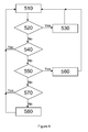
- Figure 6 is a flow chart showing the protocol to establish buffer level in the system and method of the present invention.
- FIG. 7 is a schematic diagram of the audio signal packet in accordance with the SPDIF standard.
- Figure 8 is a board Level block diagram of the various chips used in the either the transmitter or receiver of the present invention.
- Figure 9 is a detailed block diagram of the baseband and controller chip shown in Figure 8 .
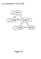
- Figure 10 is a state diagram showing the protocol used to establish communication between the transmitter and receiver of the present invention.
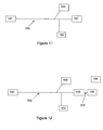
- Figure 11 is a block diagram of another embodiment of the present invention in which the data from the transmitter may be transmitted through a medium, such as a cable, to be received by a receiver.
- a medium such as a cable
- Figure 12 is a block diagram of yet another embodiment of the present invention in which data from the transmitter may be transmitted through a medium, such as a cable, terminating at an antenna to be wirelessly further transmitted to be received wirelessly by a receiver.
- a medium such as a cable
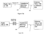
- Figures 13 are two specific embodiments of the embodiment shown in Figure 12 , showing the connection of the radio front end to the medium such as a cable.
- FIG. 1 illustrates a block diagram of an exemplary system consistent with certain aspects related to the present innovations.
- the system may comprise at least one wireless data source 110 and at least one wireless data receiver 120.
- a wireless data transmitter 110 may be comprised of a data source 130 and a source data buffer 140.
- a wireless data receiver 120 may be comprised of a receiving data sink 160 and a receiving data buffer 150.
- data may be wirelessly transmitted between the source and receiver via diverse transmitting and receiving means, including via pluralities of antenna, pluralities of frequencies and/or pluralities of channel codes.
- channel code or “channel codes” are general terms that refer to types of waveforms or waveform modulations, forward error correction applied to transmitted data, and/or other time- or modulation-related waveform coding.
- a plurality of "N" antenna may exist at both the wireless data transmitter 110 and the data receiver 120.
- antenna are denoted with “T” at the wireless data transmitter 110 (i.e., T 1 through T N ) and with “R” at the data receiver 120 (i.e., R 1 through R N ).
- the data source and data receiver may be configured to use any one of M frequencies, denoted herein by the letter “F” (i.e., F 1 through F M ).
- F i.e., F 1 through F M
- K channel codes is denoted herein by the letter “C” (i.e., C 1 through C K ).
- aspects of the innovations herein may be used in association with diversity transmission techniques.
- Antenna is usually considered as a spatial dimension
- frequency is the frequency dimension
- channel code may be considered as a time dimension.
- multiple antenna, frequencies and/or channel codes may be considered as choices in diversity selection. By changing the combination of these dimensions and their respective parameters, a change in diversity occurs in the system. While a data receiver 120 typically makes the decision by selecting a diversity choice, in certain aspects of the present innovations, the wireless data transmitter 110 can be the master and may make the diversity choice.
- the wireless data transmitter 110 and data receiver 120 may include one or more buffering components, such as source data buffer 140 and receiving data buffer 150.
- these buffer levels are monitored to implement various features and advantages. For example, with regard to data transmission and data streaming, data concerning buffer levels may be used to select diversity in multiple dimensions. Further, with regard to the data receiving and associated receiving components addressed in more detail below, data receipt, processing and decoding may be effectuated as a function of buffer levels, both those of the data source and the data receiver, as well as aggregates thereof.
- a transmitting side includes a data source 130 that sends data to a first or transmission side buffer 140 at a clock rate controlled by an oscillator 210. Data is then sent wirelessly to a second or receiving buffer 150 for eventual receipt and processing by data sink 160, which may also have its own oscillator 220 associated therewith.
- a control path 230 is provided to achieve processing and control functionality, including control of the receiving oscillator 220, feedforward, feedback, etc., such as control of certain data rate tracking and buffer over/under flow features that afford innovation over existing systems.
- a transmitting side data source 130 constantly sends data to the first buffer 140 at a fixed rate determined by the oscillator 210.
- the first data buffer 140 typically sends its contents to the second buffer 150 to prevent data overflow.
- Data sink 160 then draws data from the second buffer 150 at a constant rate determined by its oscillator 220.
- frequency offset in the oscillators 210, 220 often introduces errors to such systems. For example, if the data sink 160 draws data too slowly from the second buffer 150, this may create data overflow problems (e.g., data being lost due to insufficient storage in the second buffer 150, etc.). Conversely, if the data sink 160 draws data too quickly from the second buffer 150, this may create data underflow problems (e.g., creation and provision of invalid data to data sink 160 based on insufficient/incomplete data being read from the second buffer 150, etc.).
- a control path 230 may provide processing information to and/or control the second oscillator 220 such that the tracking processes of the data sink 160 may be implemented as a function of additional data, such as data transmission or rate information, buffer levels, etc.
- additional data such as data transmission or rate information, buffer levels, etc.
- PLL's phase-lock-loops
- buffer level tracking offers significant advantage over existing application-specific hardware, such as hardware-based clock recovery loops.
- the aggregate buffer level may be the sum of the transmitting buffer 140 and the receiving buffer 150.
- the aggregate buffer level functionality provide a variety of advantages, including information regarding the underlying data flow reasons for increases and decreases in the buffer level of the receiving buffer 150. This information enables higher demand data transmission, such as real-time or live data streaming, wireless audio and/or video transmission, etc., wherein input rate from the data source 130 should match the output rate of the data sink 160.
- the present innovations include protocols concerning acknowledgement and/or guarantee of packet transfer.
- Exemplary protocols such as guaranteeing data transfer by requiring acknowledgement from the data receiver for every packet sent are set forth in more detail below.
- Advantages stemming from these protocols include enabling the aggregate buffer levels to remain constant, even during period of difficult transmission, such as signal fading, multipath propagation, and signal interference.
- features and observations associated with the receiving buffer may also provide, for example, sufficient information on diversity transmission aspects of the system.
- features of the present innovations allow all transmission errors to be treated as transmission congestion that, i.e., affects the amount of data in the buffers.
- One embodiment of the data source 130 may comprise a DVD player. Of course, any other data source, including but not limited to CD, MP3 player, over the air transmission, HDTV etc. all may be used as a data source 130.
- the audio signals from the data source 130 are supplied to the data buffer 140 in accordance with the S/PDIF (Sony/Philips Data Interface) standard, which is also a published International IEC 60958 standard.
- the data buffer 140 comprises an audio interface circuit 142 for receiving the audio signs from the data source 130. From the audio interface circuit 142, the digitized audio signals are supplied to a transmission buffer 144 or an SRAM or a serial register 144. The level of the transmission buffer 144 is monitored and transmitted to the data receiver 120, as explained in detail hereinafter. The digital audio signals are then supplied to a transceiver 146 which sends the digital signals in packets via a first antenna Tx.
- One embodiment of the data receiver 120 may comprise a receiver antenna Rx to receive the signal from the wireless data transmitter 110, and to send acknowledgement data to the wireless data transmitter 110.
- the signals are processed by a transceiver 156, which demodulates the signal and generates digital signals, which are supplied to a receiver data buffer 150.
- the signals are supplied to an audio interface circuit 152, which supplies them to a speaker 162.
- the digital signals from the buffer 150 are also supplied to the oscillator 220 which controls the audio interface circuit 152.
- the data receiver 120 also transmits an acknowledgement (ACK) packet, i.e. the receiver 120 is a transceiver and the wireless transmitter 110 also receives the ACK packet.
- ACK acknowledgement
- the transmitter 110 /receiver 120 comprises a baseband and controller chip 300 which interfaces with a flash memory chip 310, as well as an RF transceiver 320.
- Digital signals are supplied to the baseband and controller chip 300. From the controller chip 300, the signals are supplied to the RF transceiver 320, which are then supplied to an RF power amplifier 330 (for further amplification), and finally through an antenna switch 340 to one of the antennas 350.
- the controller chip 300 is shown in greater detail in Figure 9 .
- the controller chip 300 comprises a Serial/Parallel Interface 360 which receives digital signals. The digital signals are then supplied to a bus 362. From the bus 362, the digital signals are supplied to various components of the controller chip 300, including a processor 366, a booter 364, pRAM 368, MIC (Modem Interface Controller) 380, baseband modem 370, and SPDIF interface 372.
- the processor 366 executes the software that are described hereinbelow.
- the Booter 364 is a Non-volatile memory chip containing boot up software for the processor 366. Either the flash 310 external to the chip 300 or the booter 364 may also contain the code for the software for the processor 366 to perform the methods described herein.
- the pRAM 368 or program RAM is a volatile memory which is used primary as a cache during the operation of the processor 366, and consists of 6T SRAM cells.
- the MIC 380 functions as a bridge between the baseband modem 370 and the dRAM 382. It controls the data movement between these two circuit blocks.
- the baseband modem 370 performs the function of digital modulation and digital demodulation necessary for wireless transport of data.
- the baseband modem 370 interfaces with the MIC 380 in a serial interface of clock and data ports, which is well known in the art.
- the controller chip 300 also comprises the following components: dRAM 382, DMA-IF 384, and I 2 S 378. The function of each of these components is as follows.
- the dRAM 382 serves as a volatile storage for the MIC 380. It typically is realized using 6T SRAM.
- the DMA-IF 384 is a direct memory access device designed retrieve content from the dRAM 382 without going through the processor 366.
- the data retrieved by the DMA-IF 384 is supplied to the I 2 S 378.
- the I 2 S 378 is an Inter-IC Sound circuit, which connects to the I/O pins of the chip.
- the data retrieved goes to the I 2 S 378, which is connected to the I/O pins and supplies that data to another chip.
- the I 2 S 378 acts as an input interface so the DMA 384 transfers the data from the I 2 S 378 and writes it directly into the dRAM block 382.
- the wireless data transmitter 110 has a PSN (Packet Serial Number), denoted as PSN110 while the Data receiver 120 has a PSN of PSN120.
- PSN110 PSN120.
- the wireless data transmitter 110 sends a first packet (marked with PSN110) to data receiver 120.
- the data receiver 120 receives the packet PSN110 and uses checksum, such as CRC32, or any number of other well known error correction techniques to attempt to validate the packet PSN110. If the data packet is correct, data receiver 120 sends back an ACK packet to the wireless data transmitter 110.
- the wireless data transmitter 110 uses checksum CRC32 or any other well know error correction technique attempts to validate the ACK packet. If the ACK packet is correct, which means that this packet/ACK iteration is fully completed, PSN110 increases by 1, and the associated data buffer address pointer will move accordingly. If the ACK packet is incorrect, PSN110 remains unchanged, which means the next packet to send remains the same.
- the digital data transmitted between the wireless data transmitter 110 and the data receiver 120 are controlled by independent clocks, i.e. oscillator 210 and 220, as previously discussed, a discrepancy may occur, between the transmitted packets of data and the received packets of data as stored in the buffers 140 and 150. Specifically, overflow or underflow conditions may occur.
- a method is devised whereby the level of storage in the data source buffer 140 is transmitted to the data receiver 120. Further, the level of storage in the data receiver buffer 160 is also determined.
- the aggregate buffer level i.e. the sum of the two levels is calculated.
- the sum or the Aggregate Buffer Level (ABL) is maintained at a constant or within a specified range.
- FIG. 6 there is shown a flow chart of the method of maintaining the ABL thereby preventing overflow or underflow conditions.
- four threshold values are used to achieve double threshold, low-jitter oscillator tracking.
- LH high threshold value
- LL low threshold value
- LP high threshold of normal range
- LQ low threshold of normal range
- L140 data source buffer level
- L150 data sink buffer level
- a comparison is made L > LH ?
- the tracking rate is decreased. (It will sustain in decrease mode and can only be changed by the next entry of 560/580).
- block 540 if L > LP ? is determined.
- block 550 if L ⁇ LL ? is determined.
- block 560 if L ⁇ LL then the tracking rate is increased. (It will sustain in increase mode and can only be changed by the next entry of 530/580).
- block 570 if L ⁇ LQ? Is determined.
- L is not ⁇ LQ then use normal tracking rate. (It will sustain in normal mode and can only be changed by the next entry of 530/560).
- the increase or decrease of the ABL can be made by changing the clock frequency of either the oscillator 220 or the oscillator 210.
- aggregate buffer level is usually invalid because both the transmitting and receiving buffers are typically empty at that time.
- two steps may be performed. First, the data source 130 transmits data as soon as the transmitting data buffer 140 reaches a first predetermined level, L 1 . Next, the data sink 160 begins buffer draw from the receiving buffer 150 once the receiving buffer reaches a second predetermined level, L 2 . The sum of these first and second levels, then, may be the aggregate buffer level desired for operation. Accordingly, this technique enables power-up for achieving and maintaining a desired aggregate buffer level.
- the ABL tracking algorithm can be implemented in software, which provides greater flexibility and less cost to implement. Further, ABL tracking offers significant advantage over existing application-specific hardware, such as hardware-based clock recovery loops.
- one technique for realizing aggregate buffer level information may include transmitting the level of the source buffer in a data packet header, which may then be extracted by the data receiving elements upon packet reception.
- the data receiving elements may then compute aggregate buffer level by summing the received source buffer level with the known receiving buffer level.
- it is also possible to maintain the aggregate buffer level constant by for example, changing the clock frequency of the oscillator 220. For example, when oscillators on both the source and receiving components are in a perfectly matched condition, the aggregate buffer level will remain constant.
- using the aggregate buffer level one can control the oscillators of the source and the receiver so that they match.
- Tracking features, criteria and control may also vary as a function of how aggregate buffer changes over any given transmission period. For example, if the receiving oscillator 220 is faster than the source oscillator 210, aggregate buffer level will decrease with time. Conversely, if the receiving oscillator 220 is slower than the source oscillator 210, aggregate buffer level will increase with time.
- tracking criteria can be initiated as a function of one ore more aggregate buffer level thresholds, such as high and low thresholds.
- the aggregate buffer level crosses a high threshold
- the receiving oscillator 220 needs to be driven to a higher frequency and, if the aggregate buffer level crosses a low threshold, the receiving oscillator 220 needs to be driven to a slower frequency.
- the transmission and/or reception may be subject to noise and/or interference. Accordingly, it may be desired to change either the antenna, the frequency and/or the channel code. The manner by which each of these parameters may be changed and communicated from one device to the other is described as follows.
- the transmission of each packet from the wireless data transmitter 110 must be followed by the receipt of a ACK or acknowledgment packet from the data receiver 120, received by the wireless data transmitter 110. If the ACK packet is not received by the wireless data transmitter 110, then either the packet transmitted by the wireless data transmitter 110 was not received by the data receiver 120, or interference and/or noise prevented the ACK packet from the data receiver 120 to be received by the wireless data transmitter 110. In either event, and subject to an algorithm of retries, the wireless data transmitter 110 may initiate a process to change either the antenna, the frequency or the channel codes.
- the initial antenna selection is set based upon the ratio of buffer #1 in the wireless data transmitter 110, i.e. the buffer level in the transmitter 110 to the fixed value in the ABL.
- the ABL is divided into N 2 sectors. Each sector is assigned an antenna combination. For example the combination of ⁇ T1, R1 ⁇ is chosen for sector 1, ⁇ T2, R21 ⁇ for sector 2, etc. certain permutations are not allowed in order to achieve a certain level of diversity in the system. Thus, ⁇ T2, R1 ⁇ may be the same set as ⁇ R1, T2 ⁇ . Then, the sector region in which buffer #1 resides is assigned that particular antenna.
- the data source simply changes the antenna, i.e. Tx, according to its set.
- the new antenna set information is transmitted to the data receiver using bits in the packet header.
- the data receiver 120 receives the new packet and upon receipt of a valid packet changes its antenna according to the received information.
- the change of antenna is no different than a master-slave relationship.
- the ratio of buffer #1 to the ABL is used to determine the initial frequency selection.
- the ABL is divided into M sectors, which may overlap with the N 2 antenna sectors.
- Mx For each frequency sector Mx, a frequency channel number is assigned.
- M1 is assigned frequency F1 etc.
- the data source is transmitting packets P i-2 , P i-1 , P i , P i+1 , P i-2 .
- packets P i-2 and P i-1 were transmitted at F k-1 and that for packets P i , P i+1 , P i+2 are to be transmitted at frequency F k .
- the wireless data transmitter 110 sends a packet P i-1 with a "change frequency" flag set, to notify the data receiver 120 to change to the new frequency of F k .
- the wireless data transmitter 110 then shifts to transmit packet P i at frequency F k without waiting to receive an ACK packet transmitted by the data receiver at frequency F k-1 .
- the data source receives an ACK packet from the data receiver 120 at frequency F k then it knows that the change of frequency was implemented by the data receiver 120. If, however, the wireless data transmitter 110 does not receive an ACK packet from the data receiver 120 at frequency F k then it reverts back to sending the packet P i-1 with a "change frequency" flag set, at the F k-1 frequency.
- This method of changing the frequency by anticipating that the "change frequency" flag in the packet was received and assume the data receiver 120 will be at the new frequency channel is superior to the manner of waiting to receive an ACK packet before initiating action. Specifically, if the wireless data transmitter 110 has to wait to receive the ACK packet transmitted by the data receiver 120 at the F k-1 frequency, then the system has to experience the transmission of two packets in the F k-1 frequency before initiating action. If a frequency channel is very noisy, the likelihood of two packets being successfully transmitted and received becomes a higher burden than expecting that only one packet needs to be successfully transmitted and received.
- the ratio of buffer #1 to the ABL is used to determine the initial channel code selection.
- the ABL is divided into K sectors, which may overlap with the N 2 antenna sectors or the M frequency sectors.
- Kx For each channel code sector Kx, a channel code is assigned.
- K1 is assigned channel code C1 etc.
- the data source is transmitting packets P i-2 , P i-1 , P i , P i+1 , P i+2 .
- packets P i-2 and P i-1 were transmitted at channel code C k-1 and that for packets P i , P i+1 , P i+2 are to be transmitted at channel code C k .
- the wireless data transmitter 110 sends a packet P i-1 with a "change channel code" flag set, to notify the data receiver 120 to change to the new channel code of C k .
- the wireless data transmitter 110 then shifts to transmit packet P i at channel code C k without waiting to receive an ACK packet transmitted by the data receiver at channel code C k-1 .
- the data source receives an ACK packet from the data receiver 120 at channel code C k then it knows that the change of channel code was implemented by the data receiver 120. If, however, the wireless data transmitter 110 does not receive an ACK packet from the data receiver 120 at channel code C k then it reverts back to sending the packet P i-1 with a "change channel code" flag set, at the C k-1 channel code.
- This method of changing the channel code is similar to that described for changing frequency in that by anticipating that the "change channel code" flag in the packet was received and assume the data receiver 120 will be at the new channel code is superior to the manner of waiting to receive an ACK packet before initiating action. Specifically, if the wireless data transmitter 110 has to wait to receive the ACK packet transmitted by the data receiver 120 at the channel code C k-1 , then the system has to experience the transmission of two packets in the C k-1 channel code before initiating action. If a channel code is very noisy, the likelihood of two packets being successfully transmitted and received becomes a higher burden than expecting that only one packet needs to be successfully transmitted and received.
- the audio signals from the data source 130 are supplied in wired configuration to the data buffer 140 in the S/PDIF format.
- S/PDIF format which is shown in Figure 7
- a block of data consists of 192 frames. Each frame has two subframes. Each subframe consists of 4 bits of preamble, with 28 bits (or 3.5 bytes, where one (1) byte is 8 bits) of data.
- the preamble of the first subframe of the first frame in a block is always filled with "Z" - a unique identifier.
- the wireless data transmitter 110 transmits only the data portion from each subframe/frame/block.
- the wireless data transmitter 110 strips away the preamble portion from each packet prior to wireless transmission. Thus, only 7 bytes of data are transmitted from each frame.
- each packet contains 512 bytes. However, this, of course, is an arbitrary number which may vary with implementation. Retrieval of each frame of SPDIF data requires the reading out from the data buffer 150 of seven (7) bytes.
- the audio interface circuit then appends the appropriate preamble, i.e. Z, W or M.
- the data receiver 120 assumes that the first frame received is the first frame of a block and appends the Z preamble to the first subframe, with subsequent subframes (3.5 bytes) being appended with the preamble of W or M as appropriate.
- the transmission of each packet of data signal must be followed by the receipt of an acknowledgement (ACK) packet.
- ACK acknowledgement
- the wireless data transmitter 110 will always retransmit from the beginning of the block to re-establish synchronization.
- the data receiver 120 will always assume that the first frame received at the start (or the first packet received after failure in transmission/reception) is the beginning of the block, and appends the Z preamble.
- both the data transmitter 110 and the data receiver 120 know that the start of each transmission is always from the Z preamble.
- the use of a priori established protocol of starting from the Z preamble in establishing synchronization means that a simple recovery routine can be implemented.
- the method allows byte alignment, and forces the data buffer 140 and 160 to store bytes of data. This allows compatibility with other IEC standards, such as IEC 61937.
- the wireless transmission and reception of data including processing and buffering features of the present innovations may be accomplished by various systems arranged in a variety of configurations. Examples of such systems are transmitters, receivers, transceivers and combinations of the same. Moreover, these systems may be implemented with a variety of components, including those provided by way of example above. However, again, the foregoing descriptions are exemplary and explanatory only and are not restrictive of the innovations set forth herein.
- an overall system may be comprised, inter alia, of a transmitting component and a receiving component. Because the present innovations may be applicable to and realized by the individual components, however, many of the examples above are described in the context of merely a transmitter or a receiver.
- embodiments and features of the invention may be implemented through computer-hardware, software and/or firmware.
- the systems and methods disclosed herein may be embodied in various forms including, for example, a data processor, such as a computer that also includes a database, digital electronic circuitry, firmware, software, or in combinations of them.
- a data processor such as a computer that also includes a database, digital electronic circuitry, firmware, software, or in combinations of them.
- source code editing components such as software, systems and methods consistent with the present invention may be implemented with any combination of hardware, software and/or firmware.
- the above-noted features and other aspects and principles of the present invention may be implemented in various environments.
- Such environments and related applications may be specially constructed for performing the various processes and operations according to the invention or they may include a general-purpose computer or computing platform selectively activated or reconfigured by code to provide the necessary functionality.
- the processes disclosed herein are not inherently related to any particular computer, network, architecture, environment, or other apparatus, and may be implemented by a suitable combination of hardware, software, and/or firmware.
- various general-purpose machines may be used with programs written in accordance with teachings of the invention, or it may be more convenient to construct a specialized apparatus or system to perform the required methods and techniques.
- aspects of the systems and methods disclosed herein may also be implemented as a computer program product, i.e., a computer program tangibly embodied in an information carrier, e.g., in a machine readable storage medium or element or in a propagated signal, for execution by, or to control the operation of, data processing apparatus, e.g., a programmable processor, a computer, or multiple computers.
- a computer program can be written in any form of programming language, including compiled or interpreted languages, and it can be deployed in any form, including as a stand alone program or as a module, component, subroutine, or other unit suitable for use in a computing environment.
- a computer program can be deployed to be executed on one computer or on multiple computers at one site or distributed across multiple sites and interconnected by a communication network.
- the transmitter 110 and receiver 120 can transmit and receive in sixty four frequencies, between 2.4 GHz and 5.9 GHz. Further, within each frequency, there are two possible channel codes. In the initial stage of establishing communication between the transmitter 110 and receiver 120, the transmitter 110 transmits the following to establish the "handshake" protocol between the transmitter 110 and the receiver 120.
- the handshake protocol as discussed above can be performed by a state machine and state transition paths.
- the various states are as follows:
- FIG. 11 there is shown a block diagram of another embodiment of the present invention in which data from the data source buffer 140 may be transmitted through a medium 200, such as a coaxial cable, or electrical power wiring or any other type of medium, to be received by one or more receiving data buffers 150.
- a medium 200 such as a coaxial cable, or electrical power wiring or any other type of medium
- the source data buffer 140 is connected to the wired medium 200, such as coaxial cable or electrical wiring, via a connection such as that disclosed in USP 6,856,788 , whose disclosure is incorporated herein by reference.
- the signals are then transmitted over the wired medium 200, and received by one or more receiving data buffer(s) 150 connected to the wired medium 200, without being communicated via antennas and "over the air".
- data from the data source buffer 140 is transmitted through the wired medium 200, such as a cable or power, then terminating either at a location where an transmitting antenna 108 is connected thereto or where a receiving data buffer 150 is connected thereto, or where another transmitting data source buffer 140 is connected thereto.
- the medium 200 terminates at the connection of an antenna 108, then the antenna 108 wirelessly transmits the signals which are received wirelessly by one or more receiving antennas 106.
- the data signals from the data source buffer 140 may be transmitted partially over a wired medium 200 to by pass areas of the structure which can attenuate a wireless transmitted signal, and then wireless transmit the data signal.
- the signal received by the receiving antenna 106 may be supplied to the medium 200 and then supplied to the radio 156.
- the medium 200 terminates at the connection to a receiving data buffer 150, then that portion of the signal communication is identical to that described for Figure 11 , in which the signals are transmitted and received entirely over the medium 200.
- the medium terminates at the connection to another data source buffer 140 (and more specifically to a radio front end 146, then the signal is re-transmitted by the second data source buffer (and more specifically the second radio front end) and supplied over another medium 200 to another, e.g. antenna 108.
- the use of the second data source buffer 140 may be necessary in the event, the signal attenuates over the medium 200 and the second data source buffer 140 is necessary to boost the signal strength.
- FIG. 13a there is shown two specific embodiments to implement the embodiment shown in figure 12 .
- the signals from the radio front end 146 (for the transmitter) or 156 (for the receiver) is connected to a capacitor 210 and is then connected to a matching impedance network 220, if needed.
- the matching impedance network 220 is connected to the medium 200, which is then connected to the antenna 108 (transmitting) or 106 (receiving) or to another Impedance matching network 220 (if the signal is to be connected to the receiving buffer 150 or is to be re-transmitted by another data source 140).
- the matching impedance network 220 is needed if the medium 200 has a specific impedance, such as 75 ohms for a RG6 cable, which must be matched by the impedance output from the capacitor 210. However, if the medium 200 does not require a certain impedance, then the matching impedance network 220 is not needed.
- Figure 13b shows another specific embodiment of the embodiment shown in Figure 12 . Similar to the embodiment shown in Figure 13a , in Figure 13b , the signals from the radio front end 146 (for the transmitter) or 156 (for the receiver) is connected to a transformer or hybrid device 230 which is then connected to a matching impedance network 220, if needed.
- the matching impedance network 220 is connected to the medium 200, which is then connected to the antenna 108 (transmitting) or 106 (receiving) or to another Impedance matching network 220 (if the signal is to be connected to the receiving buffer 150 or is to be re-transmitted by another data source 140).
- the matching impedance network 220 is needed if the medium 200 has a specific impedance, such as 75 ohms for a RG6 cable, which must be matched by the impedance output from the transformer 230. However, if the medium 200 does not require a certain impedance, then the matching impedance network 220 is not needed.
Landscapes
- Engineering & Computer Science (AREA)
- Signal Processing (AREA)
- Computer Networks & Wireless Communication (AREA)
- Multimedia (AREA)
- Computer Hardware Design (AREA)
- Computational Linguistics (AREA)
- Databases & Information Systems (AREA)
- Health & Medical Sciences (AREA)
- Audiology, Speech & Language Pathology (AREA)
- Human Computer Interaction (AREA)
- Physics & Mathematics (AREA)
- Acoustics & Sound (AREA)
- Communication Control (AREA)
- Mobile Radio Communication Systems (AREA)
Applications Claiming Priority (2)
| Application Number | Priority Date | Filing Date | Title |
|---|---|---|---|
| US11/809,062 US20080298232A1 (en) | 2007-05-30 | 2007-05-30 | Systems and methods for wireless transmission and reception of data including processing and buffering features |
| US12/060,825 US20080298242A1 (en) | 2007-05-30 | 2008-04-01 | Systems and methods for transmission and reception of data including processing and buffering features |
Publications (1)
| Publication Number | Publication Date |
|---|---|
| EP2034655A2 true EP2034655A2 (de) | 2009-03-11 |
Family
ID=40088043
Family Applications (1)
| Application Number | Title | Priority Date | Filing Date |
|---|---|---|---|
| EP08251764A Withdrawn EP2034655A2 (de) | 2007-05-30 | 2008-05-21 | Systeme und Verfahren für Übertragung und Empfang von Daten einschließlich Verarbeitungs- und Pufferungsfunktionen |
Country Status (5)
| Country | Link |
|---|---|
| US (1) | US20080298242A1 (de) |
| EP (1) | EP2034655A2 (de) |
| JP (1) | JP2009033739A (de) |
| KR (1) | KR20080106090A (de) |
| TW (1) | TW200901641A (de) |
Cited By (1)
| Publication number | Priority date | Publication date | Assignee | Title |
|---|---|---|---|---|
| GB2471481A (en) * | 2009-06-30 | 2011-01-05 | Nokia Corp | Data path establishment for client initiated source to sink data transfer |
Families Citing this family (8)
| Publication number | Priority date | Publication date | Assignee | Title |
|---|---|---|---|---|
| US8671332B2 (en) * | 2009-04-30 | 2014-03-11 | The Johns Hopkins University | Systems and methods for a rateless round robin protocol for adaptive error control |
| US9692476B2 (en) | 2012-04-25 | 2017-06-27 | 3M Innovative Properties Company | Wireless connectors |
| JP2013255054A (ja) * | 2012-06-06 | 2013-12-19 | Fuji Xerox Co Ltd | 送受信システム及びプログラム |
| US9209964B2 (en) * | 2014-02-19 | 2015-12-08 | Cornet Technology, Inc. | Systems and methods for DTE/DCE CESoP timing |
| JP6449707B2 (ja) * | 2015-03-31 | 2019-01-09 | Kddi株式会社 | ベースバンド信号の変換装置 |
| KR102725853B1 (ko) | 2016-12-13 | 2024-11-05 | 삼성전자주식회사 | 전자 장치 및 이의 제어 방법 |
| EP3435576A1 (de) * | 2017-07-26 | 2019-01-30 | Intel IP Corporation | Vorrichtung, verfahren und computerprogramm zur steuerung der paketübertragung |
| US12075381B2 (en) * | 2019-11-15 | 2024-08-27 | Qualcomm Incorporated | System memory flow management |
Citations (1)
| Publication number | Priority date | Publication date | Assignee | Title |
|---|---|---|---|---|
| US6856788B2 (en) | 2001-04-20 | 2005-02-15 | Mastek International | Wireless IC interconnection method and system |
Family Cites Families (19)
| Publication number | Priority date | Publication date | Assignee | Title |
|---|---|---|---|---|
| US4882754A (en) * | 1987-08-25 | 1989-11-21 | Digideck, Inc. | Data compression system and method with buffer control |
| GB8722394D0 (en) * | 1987-09-23 | 1987-10-28 | British Telecomm | Video coder |
| US5331348A (en) * | 1992-07-27 | 1994-07-19 | At&T Bell Laboratories | Adaptive leak HDTV encoder |
| WO1994011955A1 (en) * | 1992-11-06 | 1994-05-26 | Pericle Communications Company | Adaptive data rate modem |
| US5389965A (en) * | 1993-04-01 | 1995-02-14 | At&T Corp. | Video telephone station having variable image clarity |
| US5929781A (en) * | 1995-12-21 | 1999-07-27 | Hubbell Incorporated | Radio frequency controlled system for testing emergency lighting units |
| US6052384A (en) * | 1997-03-21 | 2000-04-18 | Scientific-Atlanta, Inc. | Using a receiver model to multiplex variable-rate bit streams having timing constraints |
| JP2000515711A (ja) * | 1997-05-27 | 2000-11-21 | コーニンクレッカ フィリップス エレクトロニクス エヌ ヴィ | ビデオシーケンス切替方法、その切替装置及び復号化システム |
| US6185258B1 (en) * | 1997-09-16 | 2001-02-06 | At&T Wireless Services Inc. | Transmitter diversity technique for wireless communications |
| US6678243B2 (en) * | 1997-11-14 | 2004-01-13 | Ess Technology, Inc. | Variable codec frame length |
| US6618399B1 (en) * | 1999-10-27 | 2003-09-09 | Cisco Technology, Inc. | System and method for eliminating jitter by using a starve/inspect approach to AAL1 |
| US6683531B2 (en) * | 2000-05-04 | 2004-01-27 | Trench Limited | Coupling device for providing a communications link for RF broadband data signals to a power line and method for installing same |
| US7460629B2 (en) * | 2001-06-29 | 2008-12-02 | Agere Systems Inc. | Method and apparatus for frame-based buffer control in a communication system |
| US7397877B2 (en) * | 2004-05-27 | 2008-07-08 | Intel Corporation | Clock drift compensation method for remote communications |
| US8031768B2 (en) * | 2004-12-15 | 2011-10-04 | Maxim Integrated Products, Inc. | System and method for performing optimized quantization via quantization re-scaling |
| US7421048B2 (en) * | 2005-01-20 | 2008-09-02 | Vixs Systems, Inc. | System and method for multimedia delivery in a wireless environment |
| US7778327B2 (en) * | 2005-02-08 | 2010-08-17 | Texas Instruments Incorporated | H.264 quantization |
| US7885189B2 (en) * | 2006-09-20 | 2011-02-08 | Rgb Networks, Inc. | Methods and apparatus for rate estimation and predictive rate control |
| US7706384B2 (en) * | 2007-04-20 | 2010-04-27 | Sharp Laboratories Of America, Inc. | Packet scheduling with quality-aware frame dropping for video streaming |
-
2008
- 2008-04-01 US US12/060,825 patent/US20080298242A1/en not_active Abandoned
- 2008-04-17 TW TW097113913A patent/TW200901641A/zh unknown
- 2008-05-21 EP EP08251764A patent/EP2034655A2/de not_active Withdrawn
- 2008-05-30 KR KR1020080050877A patent/KR20080106090A/ko not_active Ceased
- 2008-05-30 JP JP2008167908A patent/JP2009033739A/ja not_active Abandoned
Patent Citations (1)
| Publication number | Priority date | Publication date | Assignee | Title |
|---|---|---|---|---|
| US6856788B2 (en) | 2001-04-20 | 2005-02-15 | Mastek International | Wireless IC interconnection method and system |
Cited By (1)
| Publication number | Priority date | Publication date | Assignee | Title |
|---|---|---|---|---|
| GB2471481A (en) * | 2009-06-30 | 2011-01-05 | Nokia Corp | Data path establishment for client initiated source to sink data transfer |
Also Published As
| Publication number | Publication date |
|---|---|
| TW200901641A (en) | 2009-01-01 |
| US20080298242A1 (en) | 2008-12-04 |
| JP2009033739A (ja) | 2009-02-12 |
| KR20080106090A (ko) | 2008-12-04 |
Similar Documents
| Publication | Publication Date | Title |
|---|---|---|
| US7970016B2 (en) | Systems and methods for transmission and reception of data including frequency and channel code selection | |
| EP2034655A2 (de) | Systeme und Verfahren für Übertragung und Empfang von Daten einschließlich Verarbeitungs- und Pufferungsfunktionen | |
| KR101119674B1 (ko) | 주변 디바이스들을 위한 밀리미터-파 통신들 | |
| US20060245430A1 (en) | Method and Apparatus of a Procedure for Receiving Window Size Reconfiguration in a Communication System | |
| US5715257A (en) | System for re-transmission in data communication | |
| CN1848720B (zh) | 检测状态回报单元是否含有错误序号的方法及装置 | |
| KR20030036810A (ko) | 동적 무선 링크 적응 | |
| CN108418582A (zh) | 传输信号的方法、驱动器及系统 | |
| JP7258882B2 (ja) | 方法及び装置 | |
| CN113259710B (zh) | 改进音频传输卡顿的方法、系统及介质 | |
| CN101288328B (zh) | 控制无线通信系统中传输速率的方法 | |
| US7920490B2 (en) | Systems and methods for wireless transmission and reception of data including frequency and channel code selection | |
| US20080298443A1 (en) | Method for efficient wireless transmission and reception of audio digital signals | |
| CN109792259B (zh) | 接收器装置、发射器装置、控制接收器装置的方法、控制发射器装置的方法及计算机可读介质 | |
| US20080298232A1 (en) | Systems and methods for wireless transmission and reception of data including processing and buffering features | |
| KR100750170B1 (ko) | 통신 네트워크에서 데이터 프레임을 효율적으로 전송하는방법 및 장치 | |
| US8005038B2 (en) | Digital display system with media processor and wireless audio | |
| US7530001B2 (en) | Wireless communications system reducing unnecessary retransmission by means of a correlation value of received data with preamble and a method therefor | |
| EP2012496A2 (de) | Verfahren für das effiziente Senden und Empfangen von digitalen Audiosignalen | |
| US7401134B2 (en) | Packet processing architecture | |
| JP2001007858A (ja) | 送信装置および送信方法、並びに媒体 | |
| JP2001333048A (ja) | データ転送方式 | |
| JP5864184B2 (ja) | 通信システム | |
| CN118826962A (zh) | 一种接口电路及电子设备 |
Legal Events
| Date | Code | Title | Description |
|---|---|---|---|
| PUAI | Public reference made under article 153(3) epc to a published international application that has entered the european phase |
Free format text: ORIGINAL CODE: 0009012 |
|
| AK | Designated contracting states |
Kind code of ref document: A2 Designated state(s): AT BE BG CH CY CZ DE DK EE ES FI FR GB GR HR HU IE IS IT LI LT LU LV MC MT NL NO PL PT RO SE SI SK TR |
|
| AX | Request for extension of the european patent |
Extension state: AL BA MK RS |
|
| STAA | Information on the status of an ep patent application or granted ep patent |
Free format text: STATUS: THE APPLICATION HAS BEEN WITHDRAWN |
|
| 18W | Application withdrawn |
Effective date: 20090916 |