EP2034549A2 - Brennstoffzellenanlage mit Reformer - Google Patents
Brennstoffzellenanlage mit Reformer Download PDFInfo
- Publication number
- EP2034549A2 EP2034549A2 EP08015428A EP08015428A EP2034549A2 EP 2034549 A2 EP2034549 A2 EP 2034549A2 EP 08015428 A EP08015428 A EP 08015428A EP 08015428 A EP08015428 A EP 08015428A EP 2034549 A2 EP2034549 A2 EP 2034549A2
- Authority
- EP
- European Patent Office
- Prior art keywords
- fuel cell
- reformer
- cell system
- natural gas
- afterburner
- Prior art date
- Legal status (The legal status is an assumption and is not a legal conclusion. Google has not performed a legal analysis and makes no representation as to the accuracy of the status listed.)
- Granted
Links
Images

Classifications
-
- H—ELECTRICITY
- H01—ELECTRIC ELEMENTS
- H01M—PROCESSES OR MEANS, e.g. BATTERIES, FOR THE DIRECT CONVERSION OF CHEMICAL ENERGY INTO ELECTRICAL ENERGY
- H01M8/00—Fuel cells; Manufacture thereof
- H01M8/06—Combination of fuel cells with means for production of reactants or for treatment of residues
- H01M8/0662—Treatment of gaseous reactants or gaseous residues, e.g. cleaning
- H01M8/0675—Removal of sulfur
-
- H—ELECTRICITY
- H01—ELECTRIC ELEMENTS
- H01M—PROCESSES OR MEANS, e.g. BATTERIES, FOR THE DIRECT CONVERSION OF CHEMICAL ENERGY INTO ELECTRICAL ENERGY
- H01M8/00—Fuel cells; Manufacture thereof
- H01M8/06—Combination of fuel cells with means for production of reactants or for treatment of residues
- H01M8/0606—Combination of fuel cells with means for production of reactants or for treatment of residues with means for production of gaseous reactants
- H01M8/0612—Combination of fuel cells with means for production of reactants or for treatment of residues with means for production of gaseous reactants from carbon-containing material
- H01M8/0618—Reforming processes, e.g. autothermal, partial oxidation or steam reforming
-
- Y—GENERAL TAGGING OF NEW TECHNOLOGICAL DEVELOPMENTS; GENERAL TAGGING OF CROSS-SECTIONAL TECHNOLOGIES SPANNING OVER SEVERAL SECTIONS OF THE IPC; TECHNICAL SUBJECTS COVERED BY FORMER USPC CROSS-REFERENCE ART COLLECTIONS [XRACs] AND DIGESTS
- Y02—TECHNOLOGIES OR APPLICATIONS FOR MITIGATION OR ADAPTATION AGAINST CLIMATE CHANGE
- Y02E—REDUCTION OF GREENHOUSE GAS [GHG] EMISSIONS, RELATED TO ENERGY GENERATION, TRANSMISSION OR DISTRIBUTION
- Y02E60/00—Enabling technologies; Technologies with a potential or indirect contribution to GHG emissions mitigation
- Y02E60/30—Hydrogen technology
- Y02E60/50—Fuel cells
Definitions
- the invention relates to a fuel cell system with reformer.
- Hydrogen is a secondary energy source. He can be won in reformers. Here, hydrocarbons C n H m in the presence of catalysts with atmospheric oxygen O 2 and / or water vapor H 2 O to carbon dioxide CO 2 and molecular hydrogen H 2 .
- Natural gas is added in public supply systems an odorant, so that leaks can be detected by the appearance of the odor of the odorant.
- the odorant is often tetrahydrothiophene (THT, C 3 H 8 S) attached.
- Other odorizing agents are isopropyl mercaptan, tertiary butyl mercaptan, ethylmercaptan and di-methyl sulfide (DMS).
- natural gas containing as low sulfur sulfuric acid, carbon dioxide sulfide, carbon disulfide and mercaptans as well as di-methyl sulfide as natural sulfur-containing impurities.
- Both fuel cells and reformers contain catalysts that are irreversibly poisoned by sulfur compounds.
- the invention has for its object to provide a fuel cell system and a method for operating this fuel cell system, in which sulfur poisoning of the fuel cell is avoided.
- this is achieved according to the features of the independent device claim 1, that in a fuel cell system with a fuel cell and a reformer, the natural gas is passed through a first desulfurization and a partial stream of desulfurized natural gas is burned in a reformer burner or afterburner.
- An arranged in the exhaust pipe sulfur dioxide sensor detects whether sulfur compounds have passed the first desulfurization and were converted in the burner to sulfur dioxide.
- a warning is issued in the case in which a sulfur breakthrough is detected, and / or the fuel cell system is switched off. As a result, damage to the fuel cell is avoided.
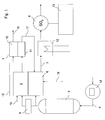
- FIG. 1 shows a fuel cell system with a fuel cell 1, which is preceded by a reformer 2 for reforming natural gas in a hydrogen-rich process gas.
- the fuel cell 1 has a cathode 10 and an anode 11.
- the reformer 2 has a reformer burner 6 for heating the reformer 2.
- In the reformer 2 also performs a water pipe 19. Alternatively, steam can be supplied.
- the output of the reformer 2 is connected to the anode 11 of the fuel cell 1.
- the output of the anode 11 is connected via an anode exhaust gas line 17 to the reformer burner 6.
- the reformer burner 6 continues to lead an air supply line 18.
- From the reformer burner 6 performs an exhaust pipe 7, in which an exhaust gas heat exchanger 12 is located. Downstream of the exhaust gas heat exchanger 12 is a sulfur dioxide sensor 8, which is connected to a transmitter 13.
- a sulfur dioxide sensor 8 Downstream of the exhaust gas heat exchanger 12 is a sulfur dioxide sensor 8, which is connected to a transmitter 13.
- the cathode 10 of the fuel cell 1 performs an air supply line 15; from the cathode 10 leads a cathode exhaust line 16 into the environment.
- the second desulfurization cartridge 9 has the task to keep 3 sulfur away from the reformer 2 at a breakthrough of the first desulfurization cartridge.
- the reformer 2 according to FIG. 1 works endothermically as a steam reformer. Therefore, in addition to desulfurized natural gas via the water pipe 19, water or steam is supplied.
- the Reformierrata is supplied by the Reformererbrenner 6 needed heat. In the reformer the following reaction takes place:
- the carbon monoxide CO with further water vapor H 2 O is further processed to carbon dioxide CO 2 and hydrogen H 2
- the hydrogen-rich process gas is passed from the reformer 2 to the anode 11 of the fuel cell 1. At the same time, air is conducted via the air supply line 15 to the cathode 10 of the fuel cell 1. In the fuel cell 1, the electrochemical reaction takes place. Anodic partial reaction (oxidation) takes place on the anode side. 2 H 2 ⁇ 4 H + + 4 e -
- the protons H + pass through an electrolyte membrane from the anode 11 to the cathode 10, at which a cathodic partial reaction (reduction) takes place O 2 + 4 e - ⁇ 2 O 2- 4H + + 2O 2- ⁇ 2H 2 O
- the corresponding electrons migrate via an electrical consumer, not shown.
- the cathode exhaust air is passed through the Kathodenab Kunststoff für 16 into the environment, while the anode exhaust gas - as described above - is used in the reformer burner 6.
- the transmitter 13 issues a warning if necessary and optionally notifies the specialist tradesman via a data transmission line, so that he can exchange the first desulfurization cartridge 3 and then again a sulfur-free operation of the fuel cell system is possible.
- the fuel cell system can continue to be operated. An immediate shutdown of the system is therefore not mandatory; to recommend a speedy exchange, however.
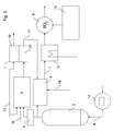
- a device according to FIG. 2 differs from a device according to FIG. 1 mainly in that in the reformer 2 an exothermic, partial oxidation according to the formula takes place.
- the reformer 2 is accordingly supplied with air via an air supply line 15 instead of water.
- the anode exhaust gas is fed to an afterburner 5 instead of a reformer burner.
- the afterburner 5 also contains natural gas that has passed the first desulfurization cartridge 3.
- sulfur dioxide in the exhaust pipe of the afterburner 5 is detected in the event of sulfur breakthrough by the first desulfurization cartridge 3.
- the fuel cell 1 may be a solid oxide fuel cell.
- Solid oxide fuel cells usually operate at temperatures around 800 ° C with high excess air ( ⁇ > 2). At about 800 ° C at the anode, the reaction O 2- + H 2 ⁇ H 2 O + 2 e - and at the cathode the reaction 1 2 ⁇ O 2 + 2 ⁇ e - ⁇ 2 ⁇ O 2 - from , SOFC solid oxide fuel cells have the advantage that also carbon monoxide can be converted in the fuel cell.
Landscapes
- Life Sciences & Earth Sciences (AREA)
- Engineering & Computer Science (AREA)
- Manufacturing & Machinery (AREA)
- Sustainable Development (AREA)
- Sustainable Energy (AREA)
- Chemical & Material Sciences (AREA)
- Chemical Kinetics & Catalysis (AREA)
- Electrochemistry (AREA)
- General Chemical & Material Sciences (AREA)
- Fuel Cell (AREA)
- Hydrogen, Water And Hydrids (AREA)
Abstract
Description
- Die Erfindung bezieht sich auf eine Brennstoffzellenanlage mit Reformer.
- In Brennstoffzellen findet eine elektrochemische Reaktion statt. Hierbei reagiert Wasserstoff mit Sauerstoff zu Wasserdampf, wobei elektrische und thermische Nutzenergie entsteht.
- Wasserstoff ist ein Sekundärenergieträger. Er kann in Reformern gewonnen werden. Hierbei reagieren Kohlenwasserstoffe CnHm in Anwesenheit von Katalysatoren mit Luftsauerstoff O2 und / oder Wasserdampf H2O zu Kohlendioxyd CO2 und molekularem Wasserstoff H2.
- Erdgas wird in öffentlichen Versorgungssystemen ein Odorierungsmittel zugesetzt, damit Leckagen am Auftreten des Geruchs des Odorierungsmittels erkannt werden können. Als Odorierungsmittel wird häufig Tetrahydrothiophen (THT, C3H8S) beigefügt. Weitere Odorierungsmittel sind Isopropylmercaptan, Tertiärbutylmercaptan, Ethylmercaptan und sowie Di-Methyl-Sulfid (DMS). Darüber hinaus enthält Erdgas als natürliche schwefelhaltige Begleitstoffe in geringen Konzentrationen Schwefelwasserstoff, Kohlenstoffoxidsulfid, Schwefelkohlenstoff und Mercaptane sowie Di-Methyl-Sulfid.
- Sowohl Brennstoffzellen, als auch Reformer enthalten Katalysatoren, welche durch Schwefelverbindungen irreversibel vergiftet werden.
- Der Erfindung liegt die Aufgabe zugrunde, eine Brennstoffzellenanlage sowie ein Verfahren zum Betreiben dieser Brennstoffzellenanlage zu schaffen, bei dem eine Schwefelvergiftung der Brennstoffzelle vermieden wird.
- Erfindungsgemäß wird dies gemäß den Merkmalen des unabhängigen Vorrichtungsanspruchs 1 dadurch erreicht, dass bei einer Brennstoffzellenanlage mit einer Brennstoffzelle und einem Reformer das Erdgas durch eine erste Entschwefelungspatrone geleitet wird und ein Teilstrom des entschwefelten Erdgases in einem Reformerbrenner oder Nachbrenner verbrannt wird. Ein in der Abgasleitung angeordneter Schwefeldioxidsensor erkennt, ob Schwefelverbindungen die erste Entschwefelungspatrone passiert haben und im Brenner zu Schwefeldioxid umgewandelt wurden.
- Vorteilhafte Ausgestaltungen ergeben sich durch die Merkmale der abhängigen Ansprüche.
- Gemäß den Merkmalen des abhängigen Verfahrensanspruchs 4 wird in dem Falle, in dem ein Schwefeldurchbruch erkannt wird, ein Warnhinweis ausgegeben und/oder die Brennstoffzellenanlage abgeschaltet. Hierdurch wird eine Beschädigung der Brennstoffzelle vermieden.
- Die Erfindung wird nun anhand der Figuren detailliert erläutert, wobei gleiche Bezugszeichen sich auf gleiche Bauteile beziehen. Hierbei zeigen:
-
Figur 1 eine erfindungsgemäße Brennstoffzellenanlage mit Dampfreformer, -
Figur 2 eine erfindungsgemäße Brennstoffzellenanlage mit partieller Oxidation und -
Figur 3 eine erfindungsgemäße Brennstoffzellenanlage mit autothermer Dampfreformer. -
Figur 1 zeigt eine Brennstoffzellenanlage mit einer Brennstoffzelle 1, der ein Reformer 2 zum Reformieren von Erdgas in ein wasserstoffreiches Prozessgas vorgelagert ist. Die Brennstoffzelle 1 verfügt über einen Kathode 10 und eine Anode 11. Der Reformer 2 verfügt über einen Reformerbrenner 6 zum Beheizen des Reformers 2. Eine Erdgaszuleitung 4, in der sich ein Durchflussmengenzähler 14 befindet, führt zu einer ersten Entschwefelungspatrone 3, von dieser führt eine Ausgangsleitung einerseits zu dem Reformerbrenner 6 und andererseits über eine zweite Entschwefelungspatrone 9 zum Reformer 2. In den Reformer 2 führt darüber hinaus eine Wasserleitung 19. Alternativ kann auch Wasserdampf zugeführt werden. Der Ausgang des Reformers 2 ist mit der Anode 11 der Brennstoffzelle 1 verbunden. Der Ausgang der Anode 11 ist über eine Anodenabgasleitung 17 mit dem Reformerbrenner 6 verbunden. In den Reformerbrenner 6 führt weiterhin eine Luftzuführleitung 18. Aus dem Reformerbrenner 6 führt eine Abgasleitung 7, in der sich ein Abgaswärmetauscher 12 befindet. Stromab des Abgaswärmetauschers 12 befindet sich ein Schwefeldioxidsensor 8, der mit einer Auswerteelektronik 13 verbunden ist. In die Kathode 10 der Brennstoffzelle 1 führt eine Luftzuführleitung 15; aus der Kathode 10 führt eine Kathodenabluftleitung 16 in die Umgebung. - Beim Betrieb der Brennstoffzellenanlage wird Erdgas über den Durchflussmengenzähler 14 in die ersten Entschwefelungspatrone 3 geleitet. Dort wird der im Erdgas befindliche Schwefel gebunden, so dass - sofern die ersten Entschwefelungspatrone 3 nicht gesättigt ist - schwefelfreies Erdgas die ersten Entschwefelungspatrone 3 verlässt. Ein Teil des entschwefelten Erdgases wird dem Reformerbrenner 6 zugeführt und zusammen mit Luft aus der Luftzuführleitung 18 und brennbarem Anodenabgas aus der Anodenabgasleitung 17 verbrannt. Die freiwerdende Wärme dient zur Beheizung des Reformers 2. Das Abgas des Reformerbrenners 6 wird im Abgaswärmetauschers 12 abgekühlt, die Wärme dabei zu Heizzwecken genutzt, und dann abgeführt, wobei das abgekühlte Abgas den Schwefeldioxidsensor 8 passiert. Das Signal des Schwefeldioxidsensors 8 wird an die Auswerteelektronik 13 weitergegeben.
- Der Teil des entschwefelten Erdgases, der nicht dem Reformerbrenner 6 zugeführt wird, gelangt über die zweite Entschwefelungspatrone 9 zum Reformer 2. Die zweite Entschwefelungspatrone 9 hat die Aufgabe, bei einem Durchbruch der ersten Entschwefelungspatrone 3 Schwefel vom Reformer 2 fern zu halten. Der Reformer 2 gemäß
Figur 1 arbeitet endotherm als Dampfreformer. Deshalb wird ihm neben entschwefeltem Erdgas über die Wasserleitung 19 Wasser oder Wasserdampf zugeführt. Dem Reformierprozess wird vom Reformererbrenner 6 die benötige Wärme zugeführt. Im Reformer findet folgende Reaktion statt:
- In einem weiteren Reformierungsschritt wird das Kohlenmonoxyd CO mit weiterem Wasserdampf H2O zu Kohlendioxyd CO2 und Wasserstoff H2 weiterverarbeitet

- Bei Hochtemperaturbrennstoffzellen kann auf diesen Schritt verzichtet werden, da diese Brennstoffzellen auch Kohlenmonoxid umsetzen können.
- Das wasserstoffreiche Prozessgas wird vom Reformer 2 zur Anode 11 der Brennstoffzelle 1 geleitet. Gleichzeitig wird Luft über die Luftzuführleitung 15 zur Kathode 10 der Brennstoffzelle 1 geführt. In der Brennstoffzelle 1 findet die elektrochemische Reaktion statt. Auf der Anodenseite findet dabei eine anodische Teilreaktion (Oxydation) statt.
2H 2 → 4H + + 4e -
- Die Protonen H + gelangen durch eine Elektrolytmembran von der Anode 11 zur Kathode 10, an welcher eine kathodische Teilreaktion (Reduktion) stattfindet
O 2 + 4e - → 2O 2-
4H + + 2O 2- → 2H 2 O
- Hierbei wandern die korrespondierenden Elektronen über einen nicht dargestellten elektrischen Verbraucher. Die Kathodenabluft wird über die Kathodenabluftleitung 16 in die Umgebung geleitet, während das Anodenabgas - wie zuvor beschrieben - im Reformerbrenner 6 genutzt wird.
- Wird im Abgas des Reformerbrenners 6 eine Schwefeldioxidemission oberhalb eines festgelegten Schwellwertes, der wenig größer als null und ebenfalls größer als die Konzentration in der Umgebungsluft ist, detektiert, so muss Schwefel die erste Entschwefelungspatrone 3 passiert haben. Die Auswerteelektronik 13 gibt daher bei Bedarf eine Warnung aus und benachrichtigt optional den Fachhandwerker über eine Datenfernleitung, damit dieser die erste Entschwefelungspatrone 3 austauschen kann und danach wieder ein schwefelfreier Betrieb der Brennstoffzellenanlage möglich ist.
- Da bei einem Durchbruch der ersten Entschwefelungspatrone 3 die zweite Entschwefelungspatrone 9 Schwefel vor dem Eintritt in den Reformer abfängt, kann die Brennstoffzellenanlage noch weiter betrieben werden. Eine sofortige Abschaltung der Anlage ist daher nicht zwingend notwendig; ein baldiger Austausch jedoch zu empfehlen.
- Eine Vorrichtung gemäß
Figur 2 unterscheidet sich von einer Vorrichtung gemäßFigur 1 hauptsächlich dadurch, dass in dem Reformer 2 eine exotherme, partielle Oxidation gemäß der Formel
- Erfindungsgemäß wird im Fall eines Schwefeldurchbruchs durch die erste Entschwefelungspatrone 3 Schwefeldioxid in der Abgasleitung des Nachbrenners 5 detektiert.
- Bei der Vorrichtung gemäß
Figur 3 findet im Reformer 2 eine autotherme Dampfreformierung statt. Hierbei finden beide oben genannten Reformerreaktionen statt, so dass die freiwerdende Energie der exothermen Reaktion genutzt wird, um die endotherme Reaktion am Laufen zu halten. Die entstehende Reaktionstemperatur kann deshalb ohne die Zufuhr beziehungsweise Abfuhr großer Wärmemengen auf einem bestimmten Niveau gehalten werden. Dem Reformer 2 werden gleichzeitig Luft und Wasser zugeführt. - Bei der Brennstoffzelle 1 kann es sich um eine Festoxidbrennstoffzelle handeln. Festoxidbrennstoffzellen arbeiten zumeist bei Temperaturen um 800°C bei hohem Luftüberschuss (λ > 2). Bei etwa 800°C läuft an der Anode die Reaktion O 2- + H 2 → H 2 O + 2e - und an der Kathode die Reaktion

- Bei Karbonatschmelzen-Brennstoffzellen (Molten Carbonate Fuel Cell) findet bei etwa 650°C die Reaktion H 2 + CO 3 2- → H 2 O + CO 2 + 2e - an der Anode und

- Erfindungsgemäß ist die Kombination verschiedener dargestellter Varianten (Art der Reformierung, Typ der Brennstoffzelle, Brennertyp) möglich. Statt Erdgas kann auch ein anderes Brenngas oder ein flüssiger Brennstoff reformiert werden.
Claims (5)
- Brennstoffzellenanlage mit mindestens einer Brennstoffzelle (1) und einem ein- oder mehrstufigen Reformer (2) zum Umwandeln von Erdgas oder eines anderen schwefelhaltigen, kohlenwasserstoffhaltigen Brennstoffs in ein molekularen Wasserstoff führendes Prozessgas und mindestens einer ersten Entschwefelungspatrone (3) in der Erdgaszuleitung (4) stromauf des Reformers (2), dadurch gekennzeichnet, dass stromab der ersten Entschwefelungspatrone (3) ein Erdgas- oder sonstiger kohlenwasserstoffhaltiger Brennstoffstrom zu einem Nachbrenner (5) oder Reformerbrenner (6) geführt wird und im Abgasstrom des Nachbrenners (5) oder Reformerbrenners (6) ein Schwefeldioxidsensor (8) angeordnet ist.
- Brennstoffzellenanlage nach Anspruch 1, dadurch gekennzeichnet, dass zwischen der der ersten Entschwefelungspatrone (3) und dem Reformer (2) eine zweite Entschwefelungspatrone (9) angeordnet ist.
- Brennstoffzellenanlage nach Anspruch 1 oder 2, dadurch gekennzeichnet, dass dem Nachbrenner (5) oder Reformerbrenner (6) zusätzlich brennstoffhaltiges Abgas der Brennstoffzelle (1) zugeführt wird.
- Verfahren zum Betreiben einer Brennstoffzellenanlage nach einem der Ansprüche 1 bis 3, dadurch gekennzeichnet, dass ein Warnsignal ausgegeben wird, wenn die mittels Schwefeldioxidsensor (8) gemessene Schwefeldioxidemission einen vorgegebenen Schwellwert überschreitet und / oder die Brennstoffzellenanlage vorzugsweise nach Ablauf einer vorbestimmten Zeit heruntergefahren wird.
- Verfahren zum Betreiben einer Brennstoffzellenanlage nach Anspruch 4, dadurch gekennzeichnet, dass das Warnsignal und / oder die Information, dass die Brennstoffzellenanlage heruntergefahren wird, mittels Datenfernübertragung weitergeleitet wird.
Applications Claiming Priority (1)
| Application Number | Priority Date | Filing Date | Title |
|---|---|---|---|
| AT0139807A AT505311B1 (de) | 2007-09-07 | 2007-09-07 | Brennstoffzellenanlage mit reformer |
Publications (3)
| Publication Number | Publication Date |
|---|---|
| EP2034549A2 true EP2034549A2 (de) | 2009-03-11 |
| EP2034549A3 EP2034549A3 (de) | 2011-04-27 |
| EP2034549B1 EP2034549B1 (de) | 2012-07-25 |
Family
ID=40083704
Family Applications (1)
| Application Number | Title | Priority Date | Filing Date |
|---|---|---|---|
| EP08015428A Not-in-force EP2034549B1 (de) | 2007-09-07 | 2008-09-01 | Brennstoffzellenanlage mit Reformer |
Country Status (4)
| Country | Link |
|---|---|
| EP (1) | EP2034549B1 (de) |
| AT (1) | AT505311B1 (de) |
| DE (1) | DE102008045355A1 (de) |
| ES (1) | ES2390378T3 (de) |
Cited By (1)
| Publication number | Priority date | Publication date | Assignee | Title |
|---|---|---|---|---|
| GB2497845A (en) * | 2011-11-30 | 2013-06-26 | Bosch Gmbh Robert | Fuel cell system with desulfurisation device and sulfur sensor |
Families Citing this family (2)
| Publication number | Priority date | Publication date | Assignee | Title |
|---|---|---|---|---|
| DE102013221618A1 (de) * | 2013-10-24 | 2015-04-30 | Robert Bosch Gmbh | Brennstoffzellenvorrichtung |
| DE102019117008A1 (de) * | 2019-06-25 | 2020-12-31 | Westnetz Gmbh | Verfahren zum Betrieb einer Netzersatzanlage sowie Netzersatzanlage |
Family Cites Families (5)
| Publication number | Priority date | Publication date | Assignee | Title |
|---|---|---|---|---|
| JP2000233901A (ja) * | 1999-02-10 | 2000-08-29 | Sanyo Electric Co Ltd | 水素製造装置および燃料電池システムならびにこれらの運転方法 |
| CN1241829C (zh) * | 2001-06-12 | 2006-02-15 | 松下电器产业株式会社 | 氢气发生装置、燃料电池系统、氢气发生装置的控制方法 |
| DE10130776B4 (de) * | 2001-06-26 | 2006-05-24 | P21 - Power For The 21St Century Gmbh | Vorrichtung zum Entfernen von Schwefel aus einem Medium sowie Brennstoffzellensystem |
| DE102004051927A1 (de) * | 2004-10-25 | 2006-04-27 | Albert-Ludwigs-Universität Freiburg | Optischer Sensor zur Bestimmung von Schwefeldioxid SO 2 in einer gasförmigen Probe |
| JP4904348B2 (ja) * | 2006-06-20 | 2012-03-28 | パナソニック株式会社 | 水素生成装置および燃料電池システム並びにこれらの運転方法 |
-
2007
- 2007-09-07 AT AT0139807A patent/AT505311B1/de not_active IP Right Cessation
-
2008
- 2008-09-01 EP EP08015428A patent/EP2034549B1/de not_active Not-in-force
- 2008-09-01 ES ES08015428T patent/ES2390378T3/es active Active
- 2008-09-01 DE DE102008045355A patent/DE102008045355A1/de not_active Withdrawn
Cited By (2)
| Publication number | Priority date | Publication date | Assignee | Title |
|---|---|---|---|---|
| GB2497845A (en) * | 2011-11-30 | 2013-06-26 | Bosch Gmbh Robert | Fuel cell system with desulfurisation device and sulfur sensor |
| GB2497845B (en) * | 2011-11-30 | 2018-06-06 | Bosch Gmbh Robert | Fuel cell system and method for operating a fuel cell system |
Also Published As
| Publication number | Publication date |
|---|---|
| AT505311B1 (de) | 2008-12-15 |
| DE102008045355A1 (de) | 2009-03-12 |
| ES2390378T3 (es) | 2012-11-12 |
| EP2034549B1 (de) | 2012-07-25 |
| EP2034549A3 (de) | 2011-04-27 |
| AT505311A4 (de) | 2008-12-15 |
Similar Documents
| Publication | Publication Date | Title |
|---|---|---|
| DE602004005306T2 (de) | Prozess zur herstellung von elektrizität und kohlendioxid | |
| DE60116602T2 (de) | Brennstoffzellen-energiegewinnungsverfahren und -system | |
| DE69614707T2 (de) | Elektrochemischer hochtemperatur - energiewandler für kohlenwasserstoffbrennstoff | |
| EP1817813B1 (de) | Brennstoffzellenheizgerät sowie verfahren zum betreiben eines brennstoffzellenheizgeräts | |
| DE10297398T5 (de) | Abschaltverfahren für Brennstoffzellen-Brennstoffaufbereitungssystem | |
| DE102020000476A1 (de) | Verfahren und Anlage zur Herstellung von Wasserstoff | |
| DE10234263A1 (de) | Verbundbrennstoffzellenanlage | |
| EP2034549B1 (de) | Brennstoffzellenanlage mit Reformer | |
| DE19941724A1 (de) | Brennstoffzelle betrieben mit Brennstoffüberschuß | |
| AT505940B1 (de) | Hochtemperaturbrennstoffzellensystem mit abgasrückführung | |
| AT507405B1 (de) | Verfahren zum betreiben von brennstoffzellensystemen mit reformern bei flüssiggas-luft-beimischung | |
| DE10297092T5 (de) | Verfahren und Vorrichtung zum Entschwefeln von Benzin oder Diesel-Brennstoff zur Verwendung in einer Brennstoffzellen-Stromerzeugungsanlage | |
| DE10257212A1 (de) | Brennstoffzellensystem und Verfahren zum Betreiben eines Brennstoffzellensystems | |
| JPH02302302A (ja) | 燃料電池発電システム | |
| JP2013101822A (ja) | 燃料電池システム | |
| DE10143656B4 (de) | Verfahren zur Erzeugung von Energie in einem Brennstoffzellen-Gesamtsystem mit Crackreaktor und Brennstoffzelle sowie Vorrichtung zur Durchführung des Verfahrens | |
| JP4476581B2 (ja) | 燃料電池発電システムとその燃料電池発電システムの制御法とその制御法を実現する制御プログラムとその制御プログラムを記録した記録媒体 | |
| DE10311785A1 (de) | Verfahren und Vorrichtung zur Bereitstellung von zu reduzierendem Reaktionsstoff für einen Anodenbereich einer Brennstoffzelle | |
| EP3227947B1 (de) | Regeneration von festoxidbrennstoffzellen | |
| DE102020000937A1 (de) | Verfahren und Anlage zur Bereitstellung eines Industrieprodukts unter Verwendung von Sauerstoff | |
| DE19926443C2 (de) | Brennstoffzellensystem und Verfahren zum Betrieb eines Brennstoffzellensystems | |
| DE68905186T2 (de) | Verfahren zur herstellung von ammoniak. | |
| JP4467925B2 (ja) | 燃料電池発電システムの制御法とその制御法を実現する制御プログラムとその制御プログラムを記録した記録媒体 | |
| DE112004000293T5 (de) | Wasserstoffgenerator zur Wasserstoffentschwefelung für Kohlenwasserstoff-Rohrstoffe | |
| JP2006032174A (ja) | 燃料電池発電システムおよびその停止方法 |
Legal Events
| Date | Code | Title | Description |
|---|---|---|---|
| PUAI | Public reference made under article 153(3) epc to a published international application that has entered the european phase |
Free format text: ORIGINAL CODE: 0009012 |
|
| AK | Designated contracting states |
Kind code of ref document: A2 Designated state(s): AT BE BG CH CY CZ DE DK EE ES FI FR GB GR HR HU IE IS IT LI LT LU LV MC MT NL NO PL PT RO SE SI SK TR |
|
| AX | Request for extension of the european patent |
Extension state: AL BA MK RS |
|
| PUAL | Search report despatched |
Free format text: ORIGINAL CODE: 0009013 |
|
| AK | Designated contracting states |
Kind code of ref document: A3 Designated state(s): AT BE BG CH CY CZ DE DK EE ES FI FR GB GR HR HU IE IS IT LI LT LU LV MC MT NL NO PL PT RO SE SI SK TR |
|
| AX | Request for extension of the european patent |
Extension state: AL BA MK RS |
|
| 17P | Request for examination filed |
Effective date: 20110905 |
|
| REG | Reference to a national code |
Ref country code: DE Ref legal event code: R079 Ref document number: 502008007756 Country of ref document: DE Free format text: PREVIOUS MAIN CLASS: H01M0008060000 Ipc: B01D0053000000 |
|
| GRAP | Despatch of communication of intention to grant a patent |
Free format text: ORIGINAL CODE: EPIDOSNIGR1 |
|
| AKX | Designation fees paid |
Designated state(s): AT BE BG CH CY CZ DE DK EE ES FI FR GB GR HR HU IE IS IT LI LT LU LV MC MT NL NO PL PT RO SE SI SK TR |
|
| RIC1 | Information provided on ipc code assigned before grant |
Ipc: B01D 53/00 20060101AFI20111209BHEP Ipc: H01M 8/06 20060101ALI20111209BHEP |
|
| RTI1 | Title (correction) |
Free format text: FUEL CELL DEVICE WITH REFORMER |
|
| GRAS | Grant fee paid |
Free format text: ORIGINAL CODE: EPIDOSNIGR3 |
|
| GRAA | (expected) grant |
Free format text: ORIGINAL CODE: 0009210 |
|
| AK | Designated contracting states |
Kind code of ref document: B1 Designated state(s): AT BE BG CH CY CZ DE DK EE ES FI FR GB GR HR HU IE IS IT LI LT LU LV MC MT NL NO PL PT RO SE SI SK TR |
|
| REG | Reference to a national code |
Ref country code: GB Ref legal event code: FG4D Free format text: NOT ENGLISH |
|
| REG | Reference to a national code |
Ref country code: CH Ref legal event code: EP |
|
| REG | Reference to a national code |
Ref country code: AT Ref legal event code: REF Ref document number: 567463 Country of ref document: AT Kind code of ref document: T Effective date: 20120815 Ref country code: IE Ref legal event code: FG4D Free format text: LANGUAGE OF EP DOCUMENT: GERMAN |
|
| REG | Reference to a national code |
Ref country code: DE Ref legal event code: R096 Ref document number: 502008007756 Country of ref document: DE Effective date: 20120920 |
|
| REG | Reference to a national code |
Ref country code: ES Ref legal event code: FG2A Ref document number: 2390378 Country of ref document: ES Kind code of ref document: T3 Effective date: 20121112 |
|
| REG | Reference to a national code |
Ref country code: NL Ref legal event code: VDEP Effective date: 20120725 |
|
| REG | Reference to a national code |
Ref country code: LT Ref legal event code: MG4D Effective date: 20120725 |
|
| PG25 | Lapsed in a contracting state [announced via postgrant information from national office to epo] |
Ref country code: HR Free format text: LAPSE BECAUSE OF FAILURE TO SUBMIT A TRANSLATION OF THE DESCRIPTION OR TO PAY THE FEE WITHIN THE PRESCRIBED TIME-LIMIT Effective date: 20120725 Ref country code: FI Free format text: LAPSE BECAUSE OF FAILURE TO SUBMIT A TRANSLATION OF THE DESCRIPTION OR TO PAY THE FEE WITHIN THE PRESCRIBED TIME-LIMIT Effective date: 20120725 Ref country code: CY Free format text: LAPSE BECAUSE OF FAILURE TO SUBMIT A TRANSLATION OF THE DESCRIPTION OR TO PAY THE FEE WITHIN THE PRESCRIBED TIME-LIMIT Effective date: 20120725 Ref country code: IS Free format text: LAPSE BECAUSE OF FAILURE TO SUBMIT A TRANSLATION OF THE DESCRIPTION OR TO PAY THE FEE WITHIN THE PRESCRIBED TIME-LIMIT Effective date: 20121125 Ref country code: NO Free format text: LAPSE BECAUSE OF FAILURE TO SUBMIT A TRANSLATION OF THE DESCRIPTION OR TO PAY THE FEE WITHIN THE PRESCRIBED TIME-LIMIT Effective date: 20121025 Ref country code: LT Free format text: LAPSE BECAUSE OF FAILURE TO SUBMIT A TRANSLATION OF THE DESCRIPTION OR TO PAY THE FEE WITHIN THE PRESCRIBED TIME-LIMIT Effective date: 20120725 |
|
| PG25 | Lapsed in a contracting state [announced via postgrant information from national office to epo] |
Ref country code: SE Free format text: LAPSE BECAUSE OF FAILURE TO SUBMIT A TRANSLATION OF THE DESCRIPTION OR TO PAY THE FEE WITHIN THE PRESCRIBED TIME-LIMIT Effective date: 20120725 Ref country code: PL Free format text: LAPSE BECAUSE OF FAILURE TO SUBMIT A TRANSLATION OF THE DESCRIPTION OR TO PAY THE FEE WITHIN THE PRESCRIBED TIME-LIMIT Effective date: 20120725 Ref country code: LV Free format text: LAPSE BECAUSE OF FAILURE TO SUBMIT A TRANSLATION OF THE DESCRIPTION OR TO PAY THE FEE WITHIN THE PRESCRIBED TIME-LIMIT Effective date: 20120725 Ref country code: GR Free format text: LAPSE BECAUSE OF FAILURE TO SUBMIT A TRANSLATION OF THE DESCRIPTION OR TO PAY THE FEE WITHIN THE PRESCRIBED TIME-LIMIT Effective date: 20121026 Ref country code: PT Free format text: LAPSE BECAUSE OF FAILURE TO SUBMIT A TRANSLATION OF THE DESCRIPTION OR TO PAY THE FEE WITHIN THE PRESCRIBED TIME-LIMIT Effective date: 20121126 Ref country code: SI Free format text: LAPSE BECAUSE OF FAILURE TO SUBMIT A TRANSLATION OF THE DESCRIPTION OR TO PAY THE FEE WITHIN THE PRESCRIBED TIME-LIMIT Effective date: 20120725 |
|
| PG25 | Lapsed in a contracting state [announced via postgrant information from national office to epo] |
Ref country code: NL Free format text: LAPSE BECAUSE OF FAILURE TO SUBMIT A TRANSLATION OF THE DESCRIPTION OR TO PAY THE FEE WITHIN THE PRESCRIBED TIME-LIMIT Effective date: 20120725 |
|
| BERE | Be: lapsed |
Owner name: VAILLANT G.M.B.H. Effective date: 20120930 |
|
| PG25 | Lapsed in a contracting state [announced via postgrant information from national office to epo] |
Ref country code: MC Free format text: LAPSE BECAUSE OF NON-PAYMENT OF DUE FEES Effective date: 20120930 Ref country code: DK Free format text: LAPSE BECAUSE OF FAILURE TO SUBMIT A TRANSLATION OF THE DESCRIPTION OR TO PAY THE FEE WITHIN THE PRESCRIBED TIME-LIMIT Effective date: 20120725 Ref country code: EE Free format text: LAPSE BECAUSE OF FAILURE TO SUBMIT A TRANSLATION OF THE DESCRIPTION OR TO PAY THE FEE WITHIN THE PRESCRIBED TIME-LIMIT Effective date: 20120725 Ref country code: RO Free format text: LAPSE BECAUSE OF FAILURE TO SUBMIT A TRANSLATION OF THE DESCRIPTION OR TO PAY THE FEE WITHIN THE PRESCRIBED TIME-LIMIT Effective date: 20120725 |
|
| PG25 | Lapsed in a contracting state [announced via postgrant information from national office to epo] |
Ref country code: SK Free format text: LAPSE BECAUSE OF FAILURE TO SUBMIT A TRANSLATION OF THE DESCRIPTION OR TO PAY THE FEE WITHIN THE PRESCRIBED TIME-LIMIT Effective date: 20120725 |
|
| PLBE | No opposition filed within time limit |
Free format text: ORIGINAL CODE: 0009261 |
|
| STAA | Information on the status of an ep patent application or granted ep patent |
Free format text: STATUS: NO OPPOSITION FILED WITHIN TIME LIMIT |
|
| REG | Reference to a national code |
Ref country code: IE Ref legal event code: MM4A |
|
| 26N | No opposition filed |
Effective date: 20130426 |
|
| PG25 | Lapsed in a contracting state [announced via postgrant information from national office to epo] |
Ref country code: IE Free format text: LAPSE BECAUSE OF NON-PAYMENT OF DUE FEES Effective date: 20120901 Ref country code: BE Free format text: LAPSE BECAUSE OF NON-PAYMENT OF DUE FEES Effective date: 20120930 Ref country code: BG Free format text: LAPSE BECAUSE OF FAILURE TO SUBMIT A TRANSLATION OF THE DESCRIPTION OR TO PAY THE FEE WITHIN THE PRESCRIBED TIME-LIMIT Effective date: 20121025 |
|
| REG | Reference to a national code |
Ref country code: DE Ref legal event code: R097 Ref document number: 502008007756 Country of ref document: DE Effective date: 20130426 |
|
| PG25 | Lapsed in a contracting state [announced via postgrant information from national office to epo] |
Ref country code: MT Free format text: LAPSE BECAUSE OF FAILURE TO SUBMIT A TRANSLATION OF THE DESCRIPTION OR TO PAY THE FEE WITHIN THE PRESCRIBED TIME-LIMIT Effective date: 20120725 |
|
| PG25 | Lapsed in a contracting state [announced via postgrant information from national office to epo] |
Ref country code: TR Free format text: LAPSE BECAUSE OF FAILURE TO SUBMIT A TRANSLATION OF THE DESCRIPTION OR TO PAY THE FEE WITHIN THE PRESCRIBED TIME-LIMIT Effective date: 20120725 |
|
| PG25 | Lapsed in a contracting state [announced via postgrant information from national office to epo] |
Ref country code: LU Free format text: LAPSE BECAUSE OF NON-PAYMENT OF DUE FEES Effective date: 20120901 |
|
| PG25 | Lapsed in a contracting state [announced via postgrant information from national office to epo] |
Ref country code: HU Free format text: LAPSE BECAUSE OF FAILURE TO SUBMIT A TRANSLATION OF THE DESCRIPTION OR TO PAY THE FEE WITHIN THE PRESCRIBED TIME-LIMIT Effective date: 20080901 |
|
| REG | Reference to a national code |
Ref country code: FR Ref legal event code: PLFP Year of fee payment: 9 |
|
| REG | Reference to a national code |
Ref country code: FR Ref legal event code: PLFP Year of fee payment: 10 |
|
| PGFP | Annual fee paid to national office [announced via postgrant information from national office to epo] |
Ref country code: CH Payment date: 20170427 Year of fee payment: 15 |
|
| PGFP | Annual fee paid to national office [announced via postgrant information from national office to epo] |
Ref country code: AT Payment date: 20170904 Year of fee payment: 10 |
|
| PGFP | Annual fee paid to national office [announced via postgrant information from national office to epo] |
Ref country code: ES Payment date: 20171011 Year of fee payment: 10 |
|
| REG | Reference to a national code |
Ref country code: FR Ref legal event code: PLFP Year of fee payment: 11 |
|
| PG25 | Lapsed in a contracting state [announced via postgrant information from national office to epo] |
Ref country code: CZ Free format text: LAPSE BECAUSE OF NON-PAYMENT OF DUE FEES Effective date: 20180901 |
|
| REG | Reference to a national code |
Ref country code: AT Ref legal event code: MM01 Ref document number: 567463 Country of ref document: AT Kind code of ref document: T Effective date: 20180901 |
|
| PG25 | Lapsed in a contracting state [announced via postgrant information from national office to epo] |
Ref country code: AT Free format text: LAPSE BECAUSE OF NON-PAYMENT OF DUE FEES Effective date: 20180901 |
|
| REG | Reference to a national code |
Ref country code: ES Ref legal event code: FD2A Effective date: 20191129 |
|
| PG25 | Lapsed in a contracting state [announced via postgrant information from national office to epo] |
Ref country code: ES Free format text: LAPSE BECAUSE OF NON-PAYMENT OF DUE FEES Effective date: 20180902 |
|
| PGFP | Annual fee paid to national office [announced via postgrant information from national office to epo] |
Ref country code: IT Payment date: 20210930 Year of fee payment: 14 Ref country code: FR Payment date: 20210924 Year of fee payment: 14 |
|
| PGFP | Annual fee paid to national office [announced via postgrant information from national office to epo] |
Ref country code: GB Payment date: 20210813 Year of fee payment: 14 Ref country code: DE Payment date: 20210816 Year of fee payment: 14 |
|
| REG | Reference to a national code |
Ref country code: DE Ref legal event code: R119 Ref document number: 502008007756 Country of ref document: DE |
|
| REG | Reference to a national code |
Ref country code: CH Ref legal event code: PL |
|
| GBPC | Gb: european patent ceased through non-payment of renewal fee |
Effective date: 20220901 |
|
| PG25 | Lapsed in a contracting state [announced via postgrant information from national office to epo] |
Ref country code: LI Free format text: LAPSE BECAUSE OF NON-PAYMENT OF DUE FEES Effective date: 20220930 Ref country code: FR Free format text: LAPSE BECAUSE OF NON-PAYMENT OF DUE FEES Effective date: 20220930 Ref country code: DE Free format text: LAPSE BECAUSE OF NON-PAYMENT OF DUE FEES Effective date: 20230401 Ref country code: CH Free format text: LAPSE BECAUSE OF NON-PAYMENT OF DUE FEES Effective date: 20220930 |
|
| PG25 | Lapsed in a contracting state [announced via postgrant information from national office to epo] |
Ref country code: IT Free format text: LAPSE BECAUSE OF NON-PAYMENT OF DUE FEES Effective date: 20220901 Ref country code: GB Free format text: LAPSE BECAUSE OF NON-PAYMENT OF DUE FEES Effective date: 20220901 |