EP2034299B1 - Exkrement nachweisender sensor - Google Patents
Exkrement nachweisender sensor Download PDFInfo
- Publication number
- EP2034299B1 EP2034299B1 EP06796293.6A EP06796293A EP2034299B1 EP 2034299 B1 EP2034299 B1 EP 2034299B1 EP 06796293 A EP06796293 A EP 06796293A EP 2034299 B1 EP2034299 B1 EP 2034299B1
- Authority
- EP
- European Patent Office
- Prior art keywords
- conductors
- urine
- detection sensor
- ink
- excrement detection
- Prior art date
- Legal status (The legal status is an assumption and is not a legal conclusion. Google has not performed a legal analysis and makes no representation as to the accuracy of the status listed.)
- Not-in-force
Links
Images


Classifications
-
- G—PHYSICS
- G01—MEASURING; TESTING
- G01N—INVESTIGATING OR ANALYSING MATERIALS BY DETERMINING THEIR CHEMICAL OR PHYSICAL PROPERTIES
- G01N27/00—Investigating or analysing materials by the use of electric, electrochemical, or magnetic means
- G01N27/02—Investigating or analysing materials by the use of electric, electrochemical, or magnetic means by investigating impedance
- G01N27/04—Investigating or analysing materials by the use of electric, electrochemical, or magnetic means by investigating impedance by investigating resistance
- G01N27/06—Investigating or analysing materials by the use of electric, electrochemical, or magnetic means by investigating impedance by investigating resistance of a liquid
- G01N27/07—Construction of measuring vessels; Electrodes therefor
-
- G—PHYSICS
- G01—MEASURING; TESTING
- G01N—INVESTIGATING OR ANALYSING MATERIALS BY DETERMINING THEIR CHEMICAL OR PHYSICAL PROPERTIES
- G01N33/00—Investigating or analysing materials by specific methods not covered by groups G01N1/00 - G01N31/00
- G01N33/48—Biological material, e.g. blood, urine; Haemocytometers
- G01N33/483—Physical analysis of biological material
- G01N33/487—Physical analysis of biological material of liquid biological material
- G01N33/493—Physical analysis of biological material of liquid biological material urine
-
- Y—GENERAL TAGGING OF NEW TECHNOLOGICAL DEVELOPMENTS; GENERAL TAGGING OF CROSS-SECTIONAL TECHNOLOGIES SPANNING OVER SEVERAL SECTIONS OF THE IPC; TECHNICAL SUBJECTS COVERED BY FORMER USPC CROSS-REFERENCE ART COLLECTIONS [XRACs] AND DIGESTS
- Y10—TECHNICAL SUBJECTS COVERED BY FORMER USPC
- Y10S—TECHNICAL SUBJECTS COVERED BY FORMER USPC CROSS-REFERENCE ART COLLECTIONS [XRACs] AND DIGESTS
- Y10S128/00—Surgery
- Y10S128/912—Connections and closures for tubes delivering fluids to or from the body
Definitions
- the present invention relates to an excrement detection sensor for detecting urination and faeces.
- a water content detection sensor for detecting presence or generation of water content at a time when the water content or water adheres between electrodes, and then, electric current passes(for example, refer to Patent Literature 1,2,3).
- Such water content detection sensors are utilized for an excrement receiver, a diaper and so on, and when the water content adheres between the electrodes by the urination, for example, the electrodes are short-circuited and the urination is thereby detected.
- the conventional water content detection sensor is provided with only a pair of electrodes, it is difficult to discriminate whether either one of evacuation or urination is detected.
- the vacuum pump is operated at the time of detecting the evacuation, and in such a case, there may cause clogging of a tube or vacuum pump with a solid component of the evacuation, which may result in difficulty of recovering the urine.
- the conventional water content detection sensor is utilized for the detection of the urination in the diaper, if the urination is detected at plural times, resistances may be changed as time elapses, which may result in erroneous operation of the detection sensor.
- JP 2000-93448 A relates to a sensor for a diaper for detecting urination and evacuation.
- an object of the present invention is to substantially eliminate defects or drawbacks encountered in the prior art mentioned above and is to provide an excrement detection sensor capable of exactly detecting the generation of the excrement.
- the present invention provides the excrement detection sensor of independent Claim 1.
- the dependent claims specify preferred but optional features.
- an excrement detection sensor comprising:
- a urine passing hole (15) may be formed so as to penetrate the carrier body (6) and the coating body (7).
- the conductors (1,2,3,4,14) may be printed on the carrier body (6), and the coating body (7) is printed so as to cover the printed conductors.
- the conductors (1,2,3,4,14) may be printed with conductive ink including conductive carbon.
- the conductors (1,2,3,4) are printed with conductive ink including conductive carbon of an amount larger than that included in the conductive ink of the high resistance conductor (14).
- the carrier body (6) or coating body (7) formed with the urine introduction ports (8) may be formed as a lamination body composed of printing ink layers including at least one layer (7b) formed of urine resist ink.
- the lamination body may include at least one layer (7a) of solvent resist ink disposed between the urine resist ink layer (7b) and the conductors (1,2,3,4,14).
- the urine resist ink may be a urethane combined ink of polyester polyol and isocyanate or a UV hardened resin ink.
- the solvent resist ink may be polyester resin ink.
- the conductors (1,2,3,4,14) may be printed with conductive ink including only of conductive carbon as conductive material.
- the two pairs of conductors(1,2,3,4) are formed between a carrier body(6) and a coating body(7) both having water-proof property and insulating property, wherein the coating body(7) or carrier body(6) is formed with an urine introduction port(8) correlating the paired conductors(1,2) and with a faeces introduction port(9) correlating the other paired conductors(3,4), and when urine enters into the urine introduction ports(8), the one pair of the conductors(1,2) are short-circuited and when faeces enters into the faeces introduction ports(9), the other one pair of the conductors(3,4) are short-circuited, whereby the urination and the evacuation can be distinctively detected.
- the excrement detection sensor is applied to an excrement receiver(17) for recovering the urine by using a saucer(16) or to a diaper, the clogging, due to the faeces, of the tube(18) of a suction machine such as vacuum pump for recovering the urine can be effectively prevented, and hence, the urine can be recovered in plural times.
- the paired conductors(1,2) are connected through a high resistance conductor(14) having a resistance higher than that of the paired conductors, an electric current passes between the conductors(1,2) through the high resistance conductor(14), so that the quality of the conductors(1,2) can be confirmed and the urination and evacuation can be thereby exactly detected.
- the coating body(7) or carrier body(6) to which the urine introduction ports(8) and the faeces introduction ports(9) are formed is formed as a lamination body of printed ink layers, and at least one(7b) of the layers is formed of an urine resist ink.
- the resistances of the conductors(1,2,3,4,14) do not change. Therefore, the generation of the urination can be exactly detected at a plurality of times.
- 1,2,3,4 ⁇ conductor 5 ⁇ excrement detection sensor, 6 ⁇ carrier body, 7 ⁇ coating body, 7a ⁇ solvent resist ink layer, 7b ⁇ urine resist ink layer, 8 ⁇ urine introduction port, 9 ⁇ faeces introduction port, 14 ⁇ ⁇ high resistance conductor, 15 ⁇ urine passing hole
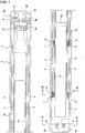
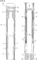
- an excrement detection sensor 5 of this embodiment two pairs of conductors 1, 2 and 3, 4 extending in parallel are sandwiched between a carrier body 6 and a coating body 7, both having water-proof property and insulating property.
- the coating body 7 is formed with an urine introduction port 8 correlating at least one pair of conductors 1 and 2, and a faeces introduction port 9 correlating the other pair of conductors 3 and 4, and when the urine A enters into the urine introduction port 8, the one pair of conductors 1 and 2 is short-circuited, and on the other hand, when the faeces B enters into the faeces introduction port 9, the other pair of conductors 3 and 4 are short-circuited.
- the carrier body 6 carries the entire structure of the excrement detection sensor 5 of this embodiment and has a belt-like shape which is bendable or flexible.
- the carrier body 6 has, for example, a length slightly longer than a length of crotch height of a human body.
- the carrier body 6 has a water-proof property and electrically insulating property. In order to confirm the quality of the circuit portion such as conductors 1, 2, 3 and 4, it is desired that the carrier body 6 is transparent.
- the carrier body 6 is formed from a biaxial orientated film of polypropylene, polyethylene, polyvinyl chloride, polyester, polyamide, polyimide, polyamideimide, polycarbonate, polystyrene, or the like.
- the carrier body 6 has a thickness of, preferably, 30 ⁇ m to 300 ⁇ m, and more preferably, 50 ⁇ m to 100 ⁇ m. It may be possible for the carrier body to be formed of an opaque material, but it may be desired to be formed from a transparent or translucent material.
- a positioning hole 12 for connecting the carrier body 6 to a connector 11 shown in Fig. 10 is formed, as occasion demands, to a base end of the carrier body 6.
- a cutout 13 and/or marker 30 may be provided, as occasion demands, for discriminating or showing positional relationship between the excrement detection sensor 5 and the connector 11.
- the two pairs of conductors 1, 2 and 3, 4 mentioned above have relatively low-resistance and extend along both side edges of the belt-shaped carrier body 6.
- an inside pair of conductors 1 and 2 are utilized for detecting urination and an outside pair of conductors 3 and 4 are utilized for detecting evacuation.
- Terminal portions 1a, 2a and 3a, 4a are formed to base ends of the two paired conductors 1, 2 and 3, 4 so as to be connected to the connector 11.
- Expanded portions 3b and 4b are also formed to tail ends opposing to the base ends connecting the connector 11 of the conductors 3 and 4 for detecting the evacuation.
- These expanded portion 3b and 4b are formed to the tail end of the carrier body 6, but the tail ends of the conductors 1 and 2 for detecting the urination are ended at portions near the base end side other than the expanded portions 3b and 4b of the conductors 3 and 4 for detecting the evacuation. That is, the tail ends of the conductors 1 and 2 for detecting the urination and their neighbouring portions, and the expanded portions 3b and 4b of the conductors 3 and 4 for detecting the evacuation correspond, respectively, to urination portion and evacuation portion of a human body.
- the conductors 1, 2, 3 and 4 inclusive of the terminal portions 1a, 2a, 3a and 4a and the expanded portions 3b and 4b are formed by printing conductive ink on the carrier body 6.
- the conductive ink is prepared by kneading a binder, conductive metal powder and a filler.
- binder there is used polyvinyl chloride group resin, polyacrylic group resin, epoxy group resin, polyester group resin, polyacrylic urethane group resin, polyolefin group resin, polyurethane group resin, phenol group resin or the like.
- conductive metal powder there is used silver, gold, copper, nickel, aluminium, conductive carbon or the like.
- a viscosity controlling agent As such filler, there is used a viscosity controlling agent, dispersant or the like.
- the conductive ink is coated, in fine belt shape, on the carrier body 6 through screen printing, direct gravure printing, flexographic printing or like printing to thereby form the conductors 1, 2, 3 and 4.
- the conductors 1 and 2 for detecting the urination are printed with, for example, a width of 1.5 mm and a thickness of 10 ⁇ m, preferably, 5 to 30 ⁇ m.
- the conductors 3 and 4 for detecting the evacuation are printed with, for example, a width of 0.5 mm and a thickness of 10 ⁇ m, preferably, 5 to 30 ⁇ m.
- These conductors 1, 2, 3 and 4 have relatively low resistance, and the resistance is set preferably, for example, to 0 to 200k ⁇ , and more preferably, less than 100k Q, by adjusting the content of the conductive metal powder in the conductive ink. In this first embodiment the resistance is about 100k ⁇ .
- the paired conductors 1 and 2 for detecting the urination are connected together through a high resistance conductor 14 having a resistance larger than that of the conductors 1 and 2.
- the resistance of the high resistance conductor 14 may be set preferably to 1M ⁇ to 10M ⁇ , and more preferably, to 2M ⁇ to 6M ⁇ .
- This high resistance conductor 14 is disposed so as to extend along inside the respective conductors 1 and 2. That is, the high resistance conductor 14 first extends from the tail end of the conductor 1 toward the base end thereof, and on the way, extends toward the other conductor 2 and then extends toward the tail end thereof along the conductor 2. As a result, the high resistance conductor 14 and the paired conductors 1 and 2 constitute a single conductor on the carrier body 6, and when a potential difference is caused between the terminals 1a and 2a of the paired conductors 1 and 2, and electric current of a constant amount passes.
- the high resistance conductor 14 is printed through a printing method as like as that mentioned with respect to the printing of the conductors 1 and 2 with a conductive ink having the component similar to that for the conductors 1 and 2.
- the high resistance conductor 14 has less amount of the conductive metal powder of the conductive ink, and as a result, the resistance of the high resistance conductor 14 is set to about several M ⁇ , for example, which is larger than that of the conductors 1 and 2.
- the high resistance conductor 14 has a fine thickness, for example of about 0.5 mm, less than that of the conductors 1 and 2 for easy visual confirmation thereof.
- the coating body 7 is applied in layer on substantially the entire surface of the carrier body 6, above the conductors 1 and 2 and the high resistance conductor 14, except the portions of the terminals 1a, 2a, 3a and 4a and various introduction holes 8 and 9 mentioned hereinafter.
- the coating body 7 serves to electrically insulate the conductors 1, 2, 3 and 4, the high resistance conductor 14, and expanded portions 3b and 4b together with the carrier body 6 from the external portion.
- the coating body 7 is formed with a printing ink.
- the printing ink is prepared by kneading a binder, a pigment and a filler.
- a binder there is used polyvinyl chloride group resin, polyacrylic group resin, epoxy group resin, polyester group resin, polyacrylic urethane group resin, polyolefin group resin, polyurethane group resin, phenol group resin or the like.
- binder there may be used, for example, a white pigment for clearly distinguishing it from the carrier body 6, the conductors 1, 2, 3 and 4, and the high resistance conductor 14.
- the filler there is used a viscosity controlling agent, dispersant or the like.
- This printing ink is coated on the carrier body 6 and the conductors 1, 2, 3 and 4 exclusive of predetermined portions such as terminal portions 1a, 2a, 3a and 4a through screen printing, direct gravure printing, or like printing to thereby form the coating body 7.
- This coating body 7 attains function of insulating film and water-proof film.
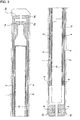
- the coating body 7 is formed with an urine introduction port 8 for introducing the urine by locally exposing the paired conductor 1 and 2 for the urination detection.
- the four urine introduction ports 8 are formed at the terminal portions, or near, of the conductors 1 and 2 for the urination detection such that respectively two ports are formed laterally symmetrically on both sides of the carrier body 6 with the longitudinal center line thereof being symmetry axis. Of course, less or more number of the urine introduction ports 8 may be adopted.
- the positions of the urine introduction ports 8 correspond to urination portion of a human body or near.
- the coating body 7 is formed with a faeces introduction port 9 for introducing the faeces by locally exposing the paired conductors 3 and 4 for the faeces detection.
- the two faeces introduction ports 9 are formed at the expanded portions 3b and 4b of the conductors 3 and 4 for the faeces detection such that respectively one port 9 is formed laterally symmetrically on both sides of the carrier body 6 with the longitudinal center line thereof being symmetry axis.
- more number of the faeces introduction ports 9 may be adopted.
- the positions of the faeces introduction ports 9 correspond to evacuation portion of a human body or near.
- These urine introduction ports 8 and the faeces introduction ports 9 are formed by being printed as non-printed portions at the same time as the printing time of the coating body 7. By forming the coating body 7 by the printing operation, the urine introduction ports 8 and the faeces introduction ports 9 can be precisely formed at small sizes. In the illustrated embodiment, although these ports 8 and 9 have rectangular shapes, they may be formed so as to provide circular shapes, elliptical shapes, square shapes and the like as occasion demands.
- the carrier body 6 is also formed with an urine passing hole 15 so as to penetrate the carrier body 6 in its thickness direction.
- the urine passing hole 15 is punched to portions between parallelly extending of the high resistance conductor 14 of the carrier body 6. More specifically, two urine passing holes 15, each having a rectangular shape, are disposed in parallel, with a connection portion 6a remaining, in the longitudinal direction of the carrier body 6.
- the urine passing hole 15 may be composed of an aggregation of a number of small holes or formed with various shapes or modes. According to this structure, the urine discharged from the human body passes through the carrier body 6 from the front surface side to the rear surface side and then received by a receiving saucer 16, mentioned herein later.
- the urine passing hole 15 may be formed, for example, through a punching process after the printing of the conductors 1, 2, 3 and 4, and the coating body 7.
- the conductors 1, 2, 3 and 4 are formed on the transparent film by being printed with inks having different colors, the presence or absence of disconnection (break of wire) of the conductors 1, 2, 3 and 4 and the presence or absence of defect of the coating body 7 can be also visually confirmed, thus simplifying the selection of quality of the excrement detection sensor 5 as a product.
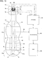
- the excrement detection sensor 5 is used, as shown in Fig. 10 , in a state of being sandwiched between various laminated sheets of non-woven fabric of a pad-shaped excrement receiver 17.
- reference numeral 17a denotes a portion receiving urine of the excrement receiver 17
- reference numeral 17b is a portion for receiving evacuation.
- the urine introduction port 8 of the excrement detection sensor 5 is positioned directly below the urine receiving portion 17a
- the faeces introduction port 9 of the excrement detection sensor 5 is positioned directly below the faeces receiving portion 17b.
- the urine receiving saucer 16 is disposed below the excrement detection sensor 5 at the urine receiving portion 17a in the excrement receiver 17.
- the saucer 16 is connected to a suction machine 19 such as vacuum pump through the tube 18, and the urine in the saucer 16 is delivered to the tank 20 by means of the suction machine 19.
- a bag portion 21, for example, as sectioning means, for sectioning the urine receiving portion 17a and the faeces receiving portion 17b is formed to the excrement receiver 17.
- the bag portion 21 is formed by covering a sheet formed of non-woven fabric from the faeces receiving portion 17b to a rear half portion of the urine receiving portion 17a and heat-sealing it on a seal line 21a.
- the urine can be prevented from entering into the faeces receiving portion 17b and the faeces can be prevented from moving to the urine receiving portion 17a.
- the excrement receiver 17 is detachably mounted to a diaper, not shown, and is applied to a groin of a human body through the diaper.
- the connector 11 electrically connected to a controller 22 is connected detachably to the base end portion of the excrement detection sensor 5.
- the connector 11 is accurately mated in position with the excrement detection sensor 5 by utilizing the positioning hole 12 and the cutout 13 formed to the base end portion of the excrement detection sensor 5, and on the other hand, the terminals 1a, 2a, 3a and 4a of the excrement detection sensor 5 are electrically connected to the terminals, not shown, on the connector side.
- the controller 22 processes by using a CPU, not shown, a signal sent from the excrement detection sensor 5 and then generates various signals.
- the controller 22 applies a voltage between the terminals 1a and 2a of the paired conductors 1 and 2, and when a constant amount of current passes to the conductors 1 and 2 through the high resistance conductor 14, it is judged that the conductors 1 and 2 include no disconnection and are normal. On the contrary, when the constant amount of current does not pass between the conductors 1 and 2, it is judged that the conductors 1 and 2 are disconnected and an alarm is generated.
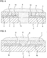
- the water content of the faeces infiltrate the faeces receiving portion 17b of the excrement receiver 17 and penetrates it on the excrement detection sensor side. Thereafter, the water content invades into the faeces introduction port 9 in contact to the surface of the excrement detection sensor 5 as shown in Fig. 5 to thereby short-circuit the other paired conductors 3 and 4. According to this short-circuit, a signal indicating the generation of evacuation is generated from the excrement detection sensor 5 to the controller 22, which then operates an alarm, not shown, to announce the generation of the evacuation.
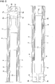
- a high resistance conductor 25 in the circuit portion of the excrement detection sensor 23 is made short in comparison with that of the first embodiment. That is, the high resistance conductor 25 is connected, at its one end, to the tail end of one of the conductors 1, extends along this conductor 1 to its base end side, passes, on the way of the extension, the connection portion 6a between the urine passing holes 15, 15 of the carrier body 6, extends toward the other conductor 2, and then is connected to the tail end of the conductor 2.
- a high resistance conductor 27 connecting the urine detection conductors 1 and 2 of an excrement detection sensor 26 is made further short in comparison with that of the second embodiment so as to extend linearly between two conductors. 1 and 2 in the width direction of the carrier body 6.
- another high resistance conductor 28 is arranged between the other paired faeces detection conductors 3 and 4.
- This high resistance conductor 28 connects linearly the expanded portions 3b and 4b of the conductors 3 and 4.
- a voltage is applied between the terminals 3a and 4a of the paired conductors 3 and 4 to thereby pass the electric current to the conductors 3 and 4 for the faeces detection.
- the excrement detection sensor is considered to be defective, and is exchanged with a normal product.
- the coating body 7, to which the urine introduction ports 8 and the faeces introduction ports 9 are formed is formed as a lamination body of printed ink layers. More specifically, the lamination body of the coating body 7 includes three printing ink layers 7a, 7b and. 7c such that a first solvent resist ink layer 7a is printed on the conductors 1, 2, 3 and 4 and the high resistance conductor 14 of the circuit portion which have already been printed, an urine resist ink layer 7b is printed on the first layer 7a, and a second solvent resist ink layer 7c is printed further on the second layer 7b. In the printing operations of the respective layers 7a, 7b and 7c, the urine introduction ports 8 and the faeces introduction ports 9 are simultaneously formed.
- Polyester resin ink will be used as the solvent resist ink, and as the urine resist ink, there will be used urethane combined ink of polyester polyol and isocyanate, or UV hardened resin ink.
- the respective conductors 1 to 4 and 14 in the first to fourth embodiments are printed with a conductive ink including only conductive carbon as conductive substance. Accordingly, the conductors 1 to 4 and 14 exhibit high resistance against urine component, and hence, the variation of the resistance value can be suppressed. As a result, in the case when such excrement detection sensor is applied to the diaper, the urination can be properly detected in plural times.
- the present invention is not limited to the described embodiments and many other changes and modifications may be made without departing from the scopes of the appended claims.
- the urine introduction ports and the faeces introduction ports in the first to fifth embodiments are provided for the coating body, these ports may be formed to the carrier body instead of the coating body.
- the coating body is formed with the printing ink layers, but it may be formed with a film member as like as the carrier body.
Landscapes
- Health & Medical Sciences (AREA)
- Life Sciences & Earth Sciences (AREA)
- Chemical & Material Sciences (AREA)
- Engineering & Computer Science (AREA)
- Physics & Mathematics (AREA)
- Biomedical Technology (AREA)
- General Physics & Mathematics (AREA)
- Biochemistry (AREA)
- Pathology (AREA)
- Immunology (AREA)
- General Health & Medical Sciences (AREA)
- Analytical Chemistry (AREA)
- Urology & Nephrology (AREA)
- Medicinal Chemistry (AREA)
- Hematology (AREA)
- Food Science & Technology (AREA)
- Molecular Biology (AREA)
- Chemical Kinetics & Catalysis (AREA)
- Electrochemistry (AREA)
- Biophysics (AREA)
- Investigating Or Analyzing Materials By The Use Of Electric Means (AREA)
- Orthopedics, Nursing, And Contraception (AREA)
- Absorbent Articles And Supports Therefor (AREA)
Claims (10)
- Exkrement nachweisender Sensor, umfassend:zwei einzelne Leiterpaare (1, 2, 3, 4), wobei die Leiter durchwegs parallel zueinander verlaufen;einen Trägerkörper (6), auf dem die Leiterpaare ausgebildet sind; undeinen die Leiter abdeckenden Beschichtungskörper (7), wobei die Leiter zwischen dem Trägerkörper und dem Beschichtungskörper angeordnet sind,wobei der Trägerkörper oder der Beschichtungskörper mit Folgendem ausgebildet ist:Urineinführungsanschlüssen (8) in Wechselbeziehung mit einem ersten Leiterpaar (1, 2) und von den Urineinführungsanschlüssen (8) beabstandeten Koteinführungsanschlüssen (9) in Wechselbeziehung mit einem zweiten Leiterpaar (3, 4); wobei eine Vielzahl von Paaren von Urineinführungsanschlüssen in einer Längsrichtung des ersten Leiterpaares angeordnet ist und wobei, wenn Urin in die Urineinführungsanschlüsse gelangt, das erste Leiterpaar kurzgeschlossen wird und, wenn Kot in die Koteinführungsanschlüsse gelangt, das zweite Leiterpaar kurzgeschlossen wird; wobei das erste und/oder das zweite Leiterpaar durch einen hochohmigen Leiter (14) mit einem höheren Widerstand als dem der Leiterpaare verbunden ist/sind.
- Exkrement nachweisender Sensor nach Anspruch 1, wobei die Leiter auf dem Trägerkörper aufgedruckt sind und der Beschichtungskörper so gedruck ist, dass er die gedruckten Leiter verdeckt.
- Exkrement nachweisender Sensor nach Anspruch 1, wobei ein Urindurchgangsloch (15) so ausgebildet ist, dass es den Trägerkörper und den Beschichtungskörper durchdringt.
- Exkrement nachweisender Sensor nach Anspruch 1, wobei die Leiter mit leitfähiger Farbe einschließlich von leitfähigem Kohlenstoff gedruckt sind.
- Exkrement nachweisender Sensor nach Anspruch 4, wobei die Leiter mit leitfähiger Farbe einschließlich von leitfähigem Kohlenstoff in einer Menge gedruckt sind, welche die in der leitfähigen Farbe des hochohmigen Leiters enthaltene Menge übersteigt.
- Exkrement nachweisender Sensor nach Anspruch 1, wobei der mit den Urineinführungsanschlüssen ausgebildete Trägerkörper oder Beschichtungskörper als Laminatkörper aus Druckfarbenlagen einschließlich von mindestens einer Lage (7b) aus Urinresistfarbe ausgebildet ist.
- Exkrement nachweisender Sensor nach Anspruch 6, wobei der Laminatkörper mindestens eine Lage von Lösungsmittelresistfarbe (7a) zwischen der Urinresistlage und den Leitern umfasst.
- Exkrement nachweisender Sensor nach Anspruch 6, wobei die Urinresistfarbe eine aus Polyesterpolyol und Isocyanat zusammengesetzte Urethanfarbe oder eine UV-gehärtete Kunstharzfarbe ist.
- Exkrement nachweisender Sensor nach Anspruch 7, wobei die Lösungsmittelresistfarbe eine Polyesterharzfarbe ist.
- Exkrement nachweisender Sensor nach Anspruch 1, wobei die Leiter mit einer leitfähigen Farbe gedruckt sind, die als leitfähiges Material nur leitfähigen Kohlenstoff enthält.
Applications Claiming Priority (2)
| Application Number | Priority Date | Filing Date | Title |
|---|---|---|---|
| JP2006180320A JP5027455B2 (ja) | 2006-06-29 | 2006-06-29 | 排泄物検知センサ |
| PCT/JP2006/314152 WO2008001475A1 (fr) | 2006-06-29 | 2006-07-18 | Capteur de détection d'excréments |
Publications (3)
| Publication Number | Publication Date |
|---|---|
| EP2034299A1 EP2034299A1 (de) | 2009-03-11 |
| EP2034299A4 EP2034299A4 (de) | 2013-11-20 |
| EP2034299B1 true EP2034299B1 (de) | 2017-01-18 |
Family
ID=38845251
Family Applications (1)
| Application Number | Title | Priority Date | Filing Date |
|---|---|---|---|
| EP06796293.6A Not-in-force EP2034299B1 (de) | 2006-06-29 | 2006-07-18 | Exkrement nachweisender sensor |
Country Status (7)
| Country | Link |
|---|---|
| US (1) | US8115643B2 (de) |
| EP (1) | EP2034299B1 (de) |
| JP (1) | JP5027455B2 (de) |
| KR (1) | KR20090031849A (de) |
| CN (1) | CN101449154B (de) |
| TW (1) | TWI405561B (de) |
| WO (1) | WO2008001475A1 (de) |
Cited By (2)
| Publication number | Priority date | Publication date | Assignee | Title |
|---|---|---|---|---|
| EP3727232B1 (de) | 2017-12-22 | 2022-01-26 | Coloplast A/S | Stomavorrichtung mit selektiven sensorpunkten und zugehörige verfahren |
| EP3727219B1 (de) | 2017-12-22 | 2023-08-09 | Coloplast A/S | Feuchtigkeitsdetektierende grundplatte für eine stomavorrichtung und system zur bestimmung der feuchtigkeitsausbreitung in einer grundplatte und/oder einem sensorbauteil |
Families Citing this family (22)
| Publication number | Priority date | Publication date | Assignee | Title |
|---|---|---|---|---|
| GB2453765A (en) * | 2007-10-18 | 2009-04-22 | Novalia Ltd | Product packaging with printed circuit and means for preventing a short circuit |
| JP4243643B1 (ja) | 2008-03-31 | 2009-03-25 | 株式会社日立製作所 | 排泄物処理装置 |
| CN102196787A (zh) * | 2008-09-19 | 2011-09-21 | 尤妮佳股份有限公司 | 尿接收器以及穿用物品 |
| CN102196786A (zh) * | 2008-09-19 | 2011-09-21 | 尤妮佳股份有限公司 | 排泄液检测装置 |
| TWM364508U (en) * | 2009-05-08 | 2009-09-11 | Sensing Tek Co Ltd | Diaper warning system |
| US8698641B2 (en) | 2010-11-02 | 2014-04-15 | Kimberly-Clark Worldwide, Inc. | Body fluid discriminating sensor |
| GB201022028D0 (en) * | 2010-12-23 | 2011-02-02 | Sca Hygiene Prod Ab | Tool for analysing liquid discharge data in an absorbent article, an absorbent article adapted for liquid dicharge data collection and a control unit |
| CN102650608B (zh) * | 2011-02-24 | 2014-04-02 | 徐菲 | 基于电化学电容器的液体检测装置、方法及纸尿裤 |
| US9907707B2 (en) | 2011-06-03 | 2018-03-06 | The Procter & Gamble Company | Sensor systems comprising auxiliary articles |
| TWI459933B (zh) * | 2011-07-15 | 2014-11-11 | Ind Tech Res Inst | 具尿布濕度檢測裝置之尿布、系統及尿布濕度檢測方法 |
| SG11201501355RA (en) * | 2012-08-28 | 2015-03-30 | Agency Science Tech & Res | An apparatus for a diaper, a system, a diaper and a method of manufacturing an electrode |
| JP6232216B2 (ja) * | 2013-06-24 | 2017-11-15 | ユニ・チャーム株式会社 | 吸収性物品 |
| DE112014003621B4 (de) | 2013-08-08 | 2022-07-14 | The Procter & Gamble Company | Sensorsysteme für absorbierende Gegenstände umfassend Sensorschleusen |
| US10285871B2 (en) | 2016-03-03 | 2019-05-14 | The Procter & Gamble Company | Absorbent article with sensor |
| CN106691699A (zh) * | 2017-01-23 | 2017-05-24 | 深圳市华阳微电子股份有限公司 | 一种大小便检测传感器、尿布及监测系统 |
| JP6941546B2 (ja) * | 2017-11-30 | 2021-09-29 | 花王株式会社 | 吸収性物品用センサーの検査方法 |
| CN210243554U (zh) * | 2018-04-02 | 2020-04-03 | 英群邦生技股份有限公司 | 一种湿度传感器以及湿度传感器卷材 |
| EP3787583A1 (de) | 2018-05-04 | 2021-03-10 | The Procter & Gamble Company | Sensorvorrichtungen und systeme zur überwachung der grundbedürfnisse eines säuglings |
| US11051996B2 (en) | 2018-08-27 | 2021-07-06 | The Procter & Gamble Company | Sensor devices and systems for monitoring the basic needs of an infant |
| US11839528B2 (en) * | 2018-10-22 | 2023-12-12 | Medline Industries, Lp | Drypad with rapid absorption and liquid removal |
| CN109481153A (zh) * | 2018-12-14 | 2019-03-19 | 深圳代科技有限公司 | 一种电子感湿吸收用品 |
| CN114793920B (zh) * | 2022-07-01 | 2022-09-30 | 至善时代智能科技(北京)有限公司 | 一种猫砂盆及宠物猫健康的监测方法 |
Family Cites Families (29)
| Publication number | Priority date | Publication date | Assignee | Title |
|---|---|---|---|---|
| GB8422940D0 (en) * | 1984-09-11 | 1984-10-17 | Smith A H | Incontinence cushion/urine collection system |
| CN85203638U (zh) * | 1985-08-21 | 1986-08-20 | 程松年 | 尿布报警器 |
| JPS63290950A (ja) | 1987-05-25 | 1988-11-28 | Kyohei Mizushima | 水分センサ− |
| JPS6425049A (en) * | 1987-07-21 | 1989-01-27 | Kyohei Mizushima | Informing system of wet diaper |
| EP0359831B2 (de) * | 1988-03-31 | 2007-06-20 | Matsushita Electric Industrial Co., Ltd. | Biosensor und dessen herstellung |
| CN2085232U (zh) * | 1991-03-23 | 1991-09-25 | 秦仲泉 | 婴儿尿便报警器 |
| EP0897570A4 (de) * | 1996-05-07 | 2000-12-27 | Knox Security Engineering Corp | Feuchtigkeitsdetektionsvorrichtung zum beispiel für windeln und windeln damit |
| JPH1030998A (ja) * | 1996-07-15 | 1998-02-03 | Akio Takahashi | 水分感知センサーを内蔵した紙おむつ |
| CN2265183Y (zh) * | 1996-09-06 | 1997-10-22 | 李伟辰 | 婴儿便溺报知尿布 |
| JPH11295250A (ja) * | 1998-04-14 | 1999-10-29 | Panetto:Kk | おむつ用センサ |
| US6246330B1 (en) * | 1998-05-29 | 2001-06-12 | Wyn Y. Nielsen | Elimination-absorber monitoring system |
| AU4274299A (en) * | 1998-06-03 | 1999-12-20 | Paul Kimsey | Moisture detector |
| CZ20004852A3 (cs) * | 1998-06-29 | 2001-08-15 | The Procter & Gamble Company | Zařízení pro manipulaci a odstranění odpadních látek |
| JP2000019136A (ja) * | 1998-07-02 | 2000-01-21 | Hokuriku Electric Ind Co Ltd | 水分検知装置 |
| AU8243098A (en) * | 1998-07-16 | 2000-02-07 | Sapporo Immuno Diagnostic Laboratory | Method for assaying l-phenylalanine and l-phenylalanine sensor |
| JP2000093448A (ja) * | 1998-09-18 | 2000-04-04 | Panetto:Kk | おむつ用センサおよびこれを内蔵したおむつ |
| JP3552997B2 (ja) * | 2000-07-04 | 2004-08-11 | 花王株式会社 | 排泄検知装置 |
| JP2002082080A (ja) | 2000-09-08 | 2002-03-22 | Matsushita Electric Works Ltd | 水分量センサ |
| US6982027B2 (en) * | 2000-10-27 | 2006-01-03 | Arkray, Inc. | Biosensor |
| EP1417662A4 (de) * | 2001-06-11 | 2008-04-16 | Wyn Y Nielsen | Eliminationsabsorber-überwachungssystem |
| WO2003010529A1 (fr) * | 2001-07-24 | 2003-02-06 | Nec Corporation | Electrode a enzyme et son procede de production |
| JP2003093448A (ja) * | 2001-09-27 | 2003-04-02 | Iura Co Ltd | ブレーキの連動機構 |
| US7176344B2 (en) * | 2002-09-06 | 2007-02-13 | Sca Hygiene Products Ab | Sensoring absorbing article |
| JP2004177120A (ja) * | 2002-10-04 | 2004-06-24 | Awajitec:Kk | 水分検知装置 |
| JP4316902B2 (ja) | 2003-03-10 | 2009-08-19 | 株式会社日立製作所 | 自動排尿処理装置およびそれに用いる尿レシーバ |
| PL1642124T3 (pl) * | 2003-06-20 | 2018-04-30 | F.Hoffmann-La Roche Ag | Biosensory elektrochemiczne |
| US20050195085A1 (en) * | 2004-03-02 | 2005-09-08 | Eugen Cretu-Petra | Wireless monitoring system of diaper wetness, motion, temperature and sound |
| TWI256470B (en) * | 2005-02-04 | 2006-06-11 | Univ Chung Yuan Christian | Multi-parameter sensor with readout circuit |
| US7394391B2 (en) * | 2005-04-29 | 2008-07-01 | Kimberly-Clark Worldwide, Inc. | Connection mechanisms in absorbent articles for body fluid signaling devices |
-
2006
- 2006-06-29 JP JP2006180320A patent/JP5027455B2/ja not_active Expired - Fee Related
- 2006-07-18 KR KR1020087025275A patent/KR20090031849A/ko not_active Application Discontinuation
- 2006-07-18 US US12/308,912 patent/US8115643B2/en not_active Expired - Fee Related
- 2006-07-18 EP EP06796293.6A patent/EP2034299B1/de not_active Not-in-force
- 2006-07-18 CN CN2006800547500A patent/CN101449154B/zh not_active Expired - Fee Related
- 2006-07-18 WO PCT/JP2006/314152 patent/WO2008001475A1/ja active Application Filing
- 2006-12-14 TW TW095146799A patent/TWI405561B/zh not_active IP Right Cessation
Non-Patent Citations (1)
| Title |
|---|
| None * |
Cited By (2)
| Publication number | Priority date | Publication date | Assignee | Title |
|---|---|---|---|---|
| EP3727232B1 (de) | 2017-12-22 | 2022-01-26 | Coloplast A/S | Stomavorrichtung mit selektiven sensorpunkten und zugehörige verfahren |
| EP3727219B1 (de) | 2017-12-22 | 2023-08-09 | Coloplast A/S | Feuchtigkeitsdetektierende grundplatte für eine stomavorrichtung und system zur bestimmung der feuchtigkeitsausbreitung in einer grundplatte und/oder einem sensorbauteil |
Also Published As
| Publication number | Publication date |
|---|---|
| US8115643B2 (en) | 2012-02-14 |
| KR20090031849A (ko) | 2009-03-30 |
| US20090326493A1 (en) | 2009-12-31 |
| CN101449154A (zh) | 2009-06-03 |
| TW200800113A (en) | 2008-01-01 |
| JP2008008791A (ja) | 2008-01-17 |
| EP2034299A4 (de) | 2013-11-20 |
| JP5027455B2 (ja) | 2012-09-19 |
| TWI405561B (zh) | 2013-08-21 |
| WO2008001475A1 (fr) | 2008-01-03 |
| CN101449154B (zh) | 2012-01-18 |
| EP2034299A1 (de) | 2009-03-11 |
Similar Documents
| Publication | Publication Date | Title |
|---|---|---|
| EP2034299B1 (de) | Exkrement nachweisender sensor | |
| US8183876B2 (en) | Water content detection sensor system | |
| CA2671163C (en) | An electric sensor web, system and a method for its manufacture | |
| US9821762B2 (en) | Seat belt buckle | |
| US20120125698A1 (en) | Seating sensor | |
| CN101223437B (zh) | 水分检测传感器 | |
| US11673488B2 (en) | Sitting sensor | |
| JP4200185B2 (ja) | 排泄物検知センサ | |
| WO2019014363A1 (en) | OCCUPANT DETECTION SYSTEM, DETECTION MAT AND ELECTRIC SWITCH | |
| JP2007205966A (ja) | ハイブリッドセンサ | |
| EP1619522A1 (de) | Kapazitive Sendeelektrode | |
| CN118031789A (zh) | 一种传感装置 |
Legal Events
| Date | Code | Title | Description |
|---|---|---|---|
| PUAI | Public reference made under article 153(3) epc to a published international application that has entered the european phase |
Free format text: ORIGINAL CODE: 0009012 |
|
| 17P | Request for examination filed |
Effective date: 20081024 |
|
| AK | Designated contracting states |
Kind code of ref document: A1 Designated state(s): AT BE BG CH CY CZ DE DK EE ES FI FR GB GR HU IE IS IT LI LT LU LV MC NL PL PT RO SE SI SK TR |
|
| AX | Request for extension of the european patent |
Extension state: AL BA HR MK RS |
|
| DAX | Request for extension of the european patent (deleted) | ||
| A4 | Supplementary search report drawn up and despatched |
Effective date: 20131022 |
|
| RIC1 | Information provided on ipc code assigned before grant |
Ipc: G01N 27/04 20060101AFI20131016BHEP |
|
| 17Q | First examination report despatched |
Effective date: 20131106 |
|
| REG | Reference to a national code |
Ref country code: DE Ref legal event code: R079 Ref document number: 602006051589 Country of ref document: DE Free format text: PREVIOUS MAIN CLASS: G01N0027040000 Ipc: G01N0027070000 |
|
| GRAP | Despatch of communication of intention to grant a patent |
Free format text: ORIGINAL CODE: EPIDOSNIGR1 |
|
| RIC1 | Information provided on ipc code assigned before grant |
Ipc: G01N 33/493 20060101ALI20160829BHEP Ipc: G01N 27/07 20060101AFI20160829BHEP |
|
| INTG | Intention to grant announced |
Effective date: 20160927 |
|
| GRAS | Grant fee paid |
Free format text: ORIGINAL CODE: EPIDOSNIGR3 |
|
| GRAA | (expected) grant |
Free format text: ORIGINAL CODE: 0009210 |
|
| AK | Designated contracting states |
Kind code of ref document: B1 Designated state(s): AT BE BG CH CY CZ DE DK EE ES FI FR GB GR HU IE IS IT LI LT LU LV MC NL PL PT RO SE SI SK TR |
|
| REG | Reference to a national code |
Ref country code: GB Ref legal event code: FG4D |
|
| REG | Reference to a national code |
Ref country code: CH Ref legal event code: EP |
|
| REG | Reference to a national code |
Ref country code: AT Ref legal event code: REF Ref document number: 863188 Country of ref document: AT Kind code of ref document: T Effective date: 20170215 |
|
| REG | Reference to a national code |
Ref country code: IE Ref legal event code: FG4D |
|
| REG | Reference to a national code |
Ref country code: DE Ref legal event code: R096 Ref document number: 602006051589 Country of ref document: DE |
|
| REG | Reference to a national code |
Ref country code: NL Ref legal event code: MP Effective date: 20170118 |
|
| REG | Reference to a national code |
Ref country code: LT Ref legal event code: MG4D |
|
| REG | Reference to a national code |
Ref country code: AT Ref legal event code: MK05 Ref document number: 863188 Country of ref document: AT Kind code of ref document: T Effective date: 20170118 |
|
| PG25 | Lapsed in a contracting state [announced via postgrant information from national office to epo] |
Ref country code: NL Free format text: LAPSE BECAUSE OF FAILURE TO SUBMIT A TRANSLATION OF THE DESCRIPTION OR TO PAY THE FEE WITHIN THE PRESCRIBED TIME-LIMIT Effective date: 20170118 |
|
| PG25 | Lapsed in a contracting state [announced via postgrant information from national office to epo] |
Ref country code: LT Free format text: LAPSE BECAUSE OF FAILURE TO SUBMIT A TRANSLATION OF THE DESCRIPTION OR TO PAY THE FEE WITHIN THE PRESCRIBED TIME-LIMIT Effective date: 20170118 Ref country code: IS Free format text: LAPSE BECAUSE OF FAILURE TO SUBMIT A TRANSLATION OF THE DESCRIPTION OR TO PAY THE FEE WITHIN THE PRESCRIBED TIME-LIMIT Effective date: 20170518 Ref country code: FI Free format text: LAPSE BECAUSE OF FAILURE TO SUBMIT A TRANSLATION OF THE DESCRIPTION OR TO PAY THE FEE WITHIN THE PRESCRIBED TIME-LIMIT Effective date: 20170118 Ref country code: GR Free format text: LAPSE BECAUSE OF FAILURE TO SUBMIT A TRANSLATION OF THE DESCRIPTION OR TO PAY THE FEE WITHIN THE PRESCRIBED TIME-LIMIT Effective date: 20170419 |
|
| PG25 | Lapsed in a contracting state [announced via postgrant information from national office to epo] |
Ref country code: PT Free format text: LAPSE BECAUSE OF FAILURE TO SUBMIT A TRANSLATION OF THE DESCRIPTION OR TO PAY THE FEE WITHIN THE PRESCRIBED TIME-LIMIT Effective date: 20170518 Ref country code: LV Free format text: LAPSE BECAUSE OF FAILURE TO SUBMIT A TRANSLATION OF THE DESCRIPTION OR TO PAY THE FEE WITHIN THE PRESCRIBED TIME-LIMIT Effective date: 20170118 Ref country code: AT Free format text: LAPSE BECAUSE OF FAILURE TO SUBMIT A TRANSLATION OF THE DESCRIPTION OR TO PAY THE FEE WITHIN THE PRESCRIBED TIME-LIMIT Effective date: 20170118 Ref country code: ES Free format text: LAPSE BECAUSE OF FAILURE TO SUBMIT A TRANSLATION OF THE DESCRIPTION OR TO PAY THE FEE WITHIN THE PRESCRIBED TIME-LIMIT Effective date: 20170118 Ref country code: PL Free format text: LAPSE BECAUSE OF FAILURE TO SUBMIT A TRANSLATION OF THE DESCRIPTION OR TO PAY THE FEE WITHIN THE PRESCRIBED TIME-LIMIT Effective date: 20170118 Ref country code: BG Free format text: LAPSE BECAUSE OF FAILURE TO SUBMIT A TRANSLATION OF THE DESCRIPTION OR TO PAY THE FEE WITHIN THE PRESCRIBED TIME-LIMIT Effective date: 20170418 Ref country code: SE Free format text: LAPSE BECAUSE OF FAILURE TO SUBMIT A TRANSLATION OF THE DESCRIPTION OR TO PAY THE FEE WITHIN THE PRESCRIBED TIME-LIMIT Effective date: 20170118 |
|
| REG | Reference to a national code |
Ref country code: DE Ref legal event code: R097 Ref document number: 602006051589 Country of ref document: DE |
|
| PG25 | Lapsed in a contracting state [announced via postgrant information from national office to epo] |
Ref country code: IT Free format text: LAPSE BECAUSE OF FAILURE TO SUBMIT A TRANSLATION OF THE DESCRIPTION OR TO PAY THE FEE WITHIN THE PRESCRIBED TIME-LIMIT Effective date: 20170118 Ref country code: CZ Free format text: LAPSE BECAUSE OF FAILURE TO SUBMIT A TRANSLATION OF THE DESCRIPTION OR TO PAY THE FEE WITHIN THE PRESCRIBED TIME-LIMIT Effective date: 20170118 Ref country code: RO Free format text: LAPSE BECAUSE OF FAILURE TO SUBMIT A TRANSLATION OF THE DESCRIPTION OR TO PAY THE FEE WITHIN THE PRESCRIBED TIME-LIMIT Effective date: 20170118 Ref country code: SK Free format text: LAPSE BECAUSE OF FAILURE TO SUBMIT A TRANSLATION OF THE DESCRIPTION OR TO PAY THE FEE WITHIN THE PRESCRIBED TIME-LIMIT Effective date: 20170118 Ref country code: EE Free format text: LAPSE BECAUSE OF FAILURE TO SUBMIT A TRANSLATION OF THE DESCRIPTION OR TO PAY THE FEE WITHIN THE PRESCRIBED TIME-LIMIT Effective date: 20170118 |
|
| PLBE | No opposition filed within time limit |
Free format text: ORIGINAL CODE: 0009261 |
|
| STAA | Information on the status of an ep patent application or granted ep patent |
Free format text: STATUS: NO OPPOSITION FILED WITHIN TIME LIMIT |
|
| PG25 | Lapsed in a contracting state [announced via postgrant information from national office to epo] |
Ref country code: DK Free format text: LAPSE BECAUSE OF FAILURE TO SUBMIT A TRANSLATION OF THE DESCRIPTION OR TO PAY THE FEE WITHIN THE PRESCRIBED TIME-LIMIT Effective date: 20170118 |
|
| 26N | No opposition filed |
Effective date: 20171019 |
|
| REG | Reference to a national code |
Ref country code: DE Ref legal event code: R119 Ref document number: 602006051589 Country of ref document: DE |
|
| PG25 | Lapsed in a contracting state [announced via postgrant information from national office to epo] |
Ref country code: SI Free format text: LAPSE BECAUSE OF FAILURE TO SUBMIT A TRANSLATION OF THE DESCRIPTION OR TO PAY THE FEE WITHIN THE PRESCRIBED TIME-LIMIT Effective date: 20170118 |
|
| REG | Reference to a national code |
Ref country code: CH Ref legal event code: PL |
|
| GBPC | Gb: european patent ceased through non-payment of renewal fee |
Effective date: 20170718 |
|
| REG | Reference to a national code |
Ref country code: IE Ref legal event code: MM4A |
|
| REG | Reference to a national code |
Ref country code: FR Ref legal event code: ST Effective date: 20180330 |
|
| PG25 | Lapsed in a contracting state [announced via postgrant information from national office to epo] |
Ref country code: CH Free format text: LAPSE BECAUSE OF NON-PAYMENT OF DUE FEES Effective date: 20170731 Ref country code: DE Free format text: LAPSE BECAUSE OF NON-PAYMENT OF DUE FEES Effective date: 20180201 Ref country code: GB Free format text: LAPSE BECAUSE OF NON-PAYMENT OF DUE FEES Effective date: 20170718 Ref country code: IE Free format text: LAPSE BECAUSE OF NON-PAYMENT OF DUE FEES Effective date: 20170718 Ref country code: LI Free format text: LAPSE BECAUSE OF NON-PAYMENT OF DUE FEES Effective date: 20170731 |
|
| PG25 | Lapsed in a contracting state [announced via postgrant information from national office to epo] |
Ref country code: FR Free format text: LAPSE BECAUSE OF NON-PAYMENT OF DUE FEES Effective date: 20170731 |
|
| REG | Reference to a national code |
Ref country code: BE Ref legal event code: MM Effective date: 20170731 |
|
| PG25 | Lapsed in a contracting state [announced via postgrant information from national office to epo] |
Ref country code: LU Free format text: LAPSE BECAUSE OF NON-PAYMENT OF DUE FEES Effective date: 20170718 |
|
| PG25 | Lapsed in a contracting state [announced via postgrant information from national office to epo] |
Ref country code: BE Free format text: LAPSE BECAUSE OF NON-PAYMENT OF DUE FEES Effective date: 20170731 |
|
| PG25 | Lapsed in a contracting state [announced via postgrant information from national office to epo] |
Ref country code: MC Free format text: LAPSE BECAUSE OF FAILURE TO SUBMIT A TRANSLATION OF THE DESCRIPTION OR TO PAY THE FEE WITHIN THE PRESCRIBED TIME-LIMIT Effective date: 20170118 Ref country code: HU Free format text: LAPSE BECAUSE OF FAILURE TO SUBMIT A TRANSLATION OF THE DESCRIPTION OR TO PAY THE FEE WITHIN THE PRESCRIBED TIME-LIMIT; INVALID AB INITIO Effective date: 20060718 |
|
| PG25 | Lapsed in a contracting state [announced via postgrant information from national office to epo] |
Ref country code: CY Free format text: LAPSE BECAUSE OF NON-PAYMENT OF DUE FEES Effective date: 20170118 |
|
| PG25 | Lapsed in a contracting state [announced via postgrant information from national office to epo] |
Ref country code: TR Free format text: LAPSE BECAUSE OF FAILURE TO SUBMIT A TRANSLATION OF THE DESCRIPTION OR TO PAY THE FEE WITHIN THE PRESCRIBED TIME-LIMIT Effective date: 20170118 |