EP2034118A2 - Blendrahmen fuer Tueren oder Tore - Google Patents
Blendrahmen fuer Tueren oder Tore Download PDFInfo
- Publication number
- EP2034118A2 EP2034118A2 EP07460028A EP07460028A EP2034118A2 EP 2034118 A2 EP2034118 A2 EP 2034118A2 EP 07460028 A EP07460028 A EP 07460028A EP 07460028 A EP07460028 A EP 07460028A EP 2034118 A2 EP2034118 A2 EP 2034118A2
- Authority
- EP
- European Patent Office
- Prior art keywords
- post
- lintel
- profile
- frame according
- hinges
- Prior art date
- Legal status (The legal status is an assumption and is not a legal conclusion. Google has not performed a legal analysis and makes no representation as to the accuracy of the status listed.)
- Withdrawn
Links
Images



Classifications
-
- E—FIXED CONSTRUCTIONS
- E06—DOORS, WINDOWS, SHUTTERS, OR ROLLER BLINDS IN GENERAL; LADDERS
- E06B—FIXED OR MOVABLE CLOSURES FOR OPENINGS IN BUILDINGS, VEHICLES, FENCES OR LIKE ENCLOSURES IN GENERAL, e.g. DOORS, WINDOWS, BLINDS, GATES
- E06B3/00—Window sashes, door leaves, or like elements for closing wall or like openings; Layout of fixed or moving closures, e.g. windows in wall or like openings; Features of rigidly-mounted outer frames relating to the mounting of wing frames
- E06B3/70—Door leaves
- E06B3/82—Flush doors, i.e. with completely flat surface
- E06B3/827—Flush doors, i.e. with completely flat surface of metal without an internal frame, e.g. with exterior panels substantially of metal
-
- E—FIXED CONSTRUCTIONS
- E06—DOORS, WINDOWS, SHUTTERS, OR ROLLER BLINDS IN GENERAL; LADDERS
- E06B—FIXED OR MOVABLE CLOSURES FOR OPENINGS IN BUILDINGS, VEHICLES, FENCES OR LIKE ENCLOSURES IN GENERAL, e.g. DOORS, WINDOWS, BLINDS, GATES
- E06B1/00—Border constructions of openings in walls, floors, or ceilings; Frames to be rigidly mounted in such openings
- E06B1/04—Frames for doors, windows, or the like to be fixed in openings
- E06B1/32—Frames composed of parts made of different materials
- E06B1/325—Frames composed of parts made of different materials comprising insulation between two metal section members
-
- E—FIXED CONSTRUCTIONS
- E06—DOORS, WINDOWS, SHUTTERS, OR ROLLER BLINDS IN GENERAL; LADDERS
- E06B—FIXED OR MOVABLE CLOSURES FOR OPENINGS IN BUILDINGS, VEHICLES, FENCES OR LIKE ENCLOSURES IN GENERAL, e.g. DOORS, WINDOWS, BLINDS, GATES
- E06B5/00—Doors, windows, or like closures for special purposes; Border constructions therefor
- E06B5/10—Doors, windows, or like closures for special purposes; Border constructions therefor for protection against air-raid or other war-like action; for other protective purposes
- E06B5/16—Fireproof doors or similar closures; Adaptations of fixed constructions therefor
-
- E—FIXED CONSTRUCTIONS
- E06—DOORS, WINDOWS, SHUTTERS, OR ROLLER BLINDS IN GENERAL; LADDERS
- E06B—FIXED OR MOVABLE CLOSURES FOR OPENINGS IN BUILDINGS, VEHICLES, FENCES OR LIKE ENCLOSURES IN GENERAL, e.g. DOORS, WINDOWS, BLINDS, GATES
- E06B5/00—Doors, windows, or like closures for special purposes; Border constructions therefor
- E06B5/10—Doors, windows, or like closures for special purposes; Border constructions therefor for protection against air-raid or other war-like action; for other protective purposes
- E06B5/16—Fireproof doors or similar closures; Adaptations of fixed constructions therefor
- E06B5/161—Profile members therefor
Definitions
- the subject of the invention is a frame for doors or gates with hinged wings, especially with fire-proof metal wings with large mass.
- a window frame for doors which consists of a protective frame and a support frame, which lie on each other.
- Each of these frames has two vertical, lateral posts, which are transversely connected at the top by means of a horizontal lintel.
- the support frame of the frame is made of a thick metal angle, while the protective frame consists of a complicated metal profile.
- the side posts and the lintel of the protective frame usually form separate elements, which are interconnected by means of corner joints.
- the support frame is attached by means of anchors on the edge of the door opening.
- the protective frame is attached by means of countersunk screws on the lateral surfaces of the support frame.
- hinge pins protrude from one or both posts of the protective frame on which these wings are placed. Because the support frame and the protective frame are unitary elements and have constant dimensions, the field of the door opening must be precisely matched to the distance of the posts and the level of the lintel and the edges of the door opening must have smooth surfaces.
- Frame for doors or gates which has two vertical posts which are connected at the top with a horizontal lintel, each of these elements consists of a superimposed protective part and a support member, and at least one post has hinges for mounting a hinged wing
- the support part of the hinged post and the support member of the lintel is formed at least of a portion of a thick-walled profile which is fixed to the edge of the entrance opening, wherein the hinges are connected to the support member of the post.
- the protection part of each Post and lintel is made of a thin complex profile.
- the protective part of the post with hinges has longitudinal openings through which hinge pins protrude from the supporting part of the post.
- the supporting part of the post with hinges is divided into several sections, which are arranged one above the other at intervals.
- the upper portion of the profile, which forms the supporting part of the post is most advantageously angularly connected to the supporting part of the lintel, which is spread over the entire length of the lintel.
- the supporting part of the lintel forms a single section of the profile, which is arranged in the middle of the lintel and separated from the supporting parts of the posts.
- the support member of the post on the side of the door lock forms most conveniently a portion of a thick-walled profile, which is attached to the edge of the door opening and has an opening for the introduction of the bolt from the door lock.
- the supporting part of the post is most advantageously made of steel angle or flat steel.
- the protective part of the post and the lintel is best made of two parallel profile strips, the adjacent edges of which are removed from each other and attached to the abutment liner of thermal insulation.
- the protective part of the post as well as the lintel forms a single profile strip, which has a Quer querfach in its middle part. If the post of the frame is on the side of the door lock without support member, then the protective part of this post has an opening for the introduction of the bolt from the door lock.
- the support members of the posts of the frame made of separate sections of a profile with hinge pins and are not connected in principle with the support member of the lintel, these elements can be attached to the edge of the entrance opening in the initial phase of their construction.
- the protective parts of the frame can thus be mounted in the termination phase, when the edge surfaces of the entrance opening are covered with a layer of mortar. Because the protective parts of the posts have no connections with the hinges and in connection therewith are not subjected to any significant mechanical stresses, the protective parts of the frame can be made of lightweight, thin-walled profile become.
- the frame according to the invention is particularly suitable when inserting fire-proof doors or gates, because in contrast to the compact frame whose divided on supporting sections posts are not subject to harmful deformations under the influence of high temperatures or direct fire.
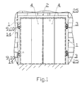
- Fig. 1 represents the front view of a window frame with pivotable, double-leaf door
- Fig. 2 the front view of a window frame with pivoting single-leaf door
- Fig. 3 The horizontal cross-section of the post of the frame, the support member has the shape of a steel angle and the protective part consists of two moldings
- Fig. 4 the horizontal cross section of the post, the supporting part being in the form of flat steel and the protective part being a single profiled strip
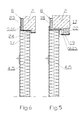
- Fig. 5 the vertical cross-section of the lintel with protective part of two moldings
- Fig. 5 the vertical cross-section of the lintel with protective part of two moldings
- the frame according to the invention has two vertical, lateral posts 1, which are connected to the horizontal lintel 2 above.
- both posts 1 In the frame of a double-winged, up Fig. 1 shown gates, both posts 1 have hinges 3, are placed on the pivoting wings 4 of the gate.
- the left post 1 In the on Fig. 2 shown frame for one-wing door, the left post 1 has hinges 3 for placing the pivoting wings 5, while the right post 1 is provided with an opening 6 , in which the not shown in the drawing latch of the door lock 7 is introduced.
- Each post 1 and lintel 2 consists of a protective part 8 and a support member 9, which are placed on each other.
- the support member 9 of the post 1 with hinges 3 is divided into two sections 10 of thick metal profile, which are arranged one above the other at intervals.
- Both sections 10 of the profile are by means of expansion dowel 11 at the edge 12 of Fixed inlet opening 13 and equipped with hinge pin 14 .
- the support member 9 of the right post 1 on the side of the door lock 7 forms the portion 10 a , which is made of thick metal profile.
- the section 10a of the profile is located approximately half the height of the post 1 and is fastened with the expansion dowels, not shown in the drawing, at the edge 12 of the inlet opening 13 .
- the opening 6 for the introduction of the bolt, not shown, is formed.
- the post 1 on the side of the door lock 7 can be entirely without support member 9 and consist exclusively of the protective part 8 .
- the opening, not shown on the drawing for the latch of the door lock 7 , not shown, is formed in the protective part 8 of the post 1 .
- the upper portion 10 of the profile, which forms the supporting part 9 of the post 1 is connected at an angle to the supporting part 9 of the lintel 2 , which is also formed from the section 10 of the profile and distributed over the entire length of the lintel 2 .
- the supporting part 9 of the lintel 2 has the shape of a single section 10 of the profile, which is arranged in the middle of the lintel 2 and separated from the supporting parts 9 of the post 1 .
- the supporting parts 9 of the posts 1 and the lintel 2 are made of steel angle 15 or flat steel 16 . At the vertical edges of the steel angle 15 and the flat steel 16 are the final mortar layers 17 at.
- the guard 8 of each post 1 and lintel 2 is made of thin-walled complicated profile.
- the protective parts 8 of the post 1 and the lintel 2 consist of two parallel profile strips 18 and 19. Their adjacent edges 20, 21 are spaced from each other and secured with countersunk screws to the abutment liner 22 of non-combustible thermal insulation material.
- the profile strip 18 is fixed by means of countersunk screws on the steel angle 15 of the support member 9 of the post 1 .
- the guard 8 of each post 1 and lintel 2 on Fig. 4 and 6 The frame shown has the form of a single profile strip 23, which has a quer querfach 24 in its middle part.
- the profile strips 18, 19, 23 can be made of any material, especially be made of sheet metal.
- the protective part 8 of the post 1 with hinges 3 has longitudinal openings 25, protrude through the hinge pin 14 from the support member 9 of the post 1 .
Landscapes
- Engineering & Computer Science (AREA)
- Civil Engineering (AREA)
- Structural Engineering (AREA)
- Hinges (AREA)
- Special Wing (AREA)
- Liquid Crystal (AREA)
- Door And Window Frames Mounted To Openings (AREA)
- Superconductors And Manufacturing Methods Therefor (AREA)
Abstract

Description
- Der Gegenstand des Erfindung ist ein Blendrahmen für Türen oder Tore mit schwenkbaren Flügeln, besonders mit brandsicheren Metallflügeln mit großer Masse.
- Bekannt ist ein Blendrahmen für Türen, welcher aus einem Schutzrahmen und einem Tragrahmen besteht, welche aufeinander liegen. Jeder dieser Rahmen besitzt zwei senkrechte, seitliche Pfosten, welche oben mittels eines waagerechten Torsturzes quer verbunden sind. Der Tragrahmen des Blendrahmens ist aus einem dickwändigen Metallwinkel gebaut, dagegen der Schutzrahmen besteht aus einem komplizierten Metallprofil. Die seitlichen Pfosten sowie der Türsturz des Schutzrahmens bilden meistens separate Elemente, welche mittels Eckverbindungen miteinander verbunden sind. Der Tragrahmen ist mittels Anker am Rand der Türöffnung befestigt. Dagegen der Schutzrahmen ist mittels Senkschrauben an den seitlichen Flächen des Tragrahmens befestigt. In Anhängigkeit von der Zahl der Türflügeln, ragen aus einem oder aus beiden Pfosten des Schutzrahmens Scharnierbolzen heraus, auf welchen diese Flügeln aufgesetzt sind. Weil der Tragrahmen und der Schutzrahmen einheitliche Elemente sind sowie konstante Abmessungen haben, muß das Feld der Türöffnung an den Abstand der Pfosten und des Niveaus des Türsturzes genau angepasst sein und die Ränder der Türöffnung müssen glatte Flächen haben.
- Blendrahmen für Türen oder Tore, welcher zwei senkrechte Pfosten hat, die oben mit einem waagerechten Türsturz verbunden sind, wobei jedes dieser Elemente aus einem aufeinanderliegenden Schutzteil und einem Tragteil besteht, und wenigstens ein Pfosten Scharniere zum Aufsetzen eines schwenkbaren Flügels hat, ist gemäß der Erfindung gekennzeichnet dadurch, daß der Tragteil des mit Scharnieren ausgerüsteten Pfostens sowie der Tragteil des Türsturzes wenigstens aus einem Abschnitt eines dickwändigen Profils gebildet ist, welcher am Rand der Eingangsöffnung befestigt ist, wobei die Scharniere mit dem Tragteil des Pfostens verbunden sind. Der Schutzteil jedes Pfostens und Türsturzes ist aus einem dünnwändigen komplizierten Profil gebildet. Darüber hinaus der Schutzteil des Pfostens mit Scharnieren hat Längsöffnungen, durch die Scharnierbolzen aus dem Tragteil des Pfostens herausragen. In der günstigen Lösung der Erfindung, ist der Tragteil des Pfostens mit Scharnieren auf einige Abschnitte geteilt, welche in Abständen übereinander angeordnet sind. Der obere Abschnitt des Profils, welcher den Tragteil des Pfostens bildet, ist am günstigsten mit dem Tragteil des Türsturzes winkelig verbunden, welcher auf der ganzen Länge des Türsturzes ausgebreitet ist. In einer anderen günstigen Lösung der Tragteil des Türsturzes bildet einen einzelnen Abschnitt des Profils, welcher in der Mitte des Türsturzes angeordnet und von den Tragteilen der Pfosten getrennt ist. Der Tragteil des Pfostens auf der Seite des Türschlosses bildet am günstigsten ein Abschnitt eines dickwändigen Profils, welches am Rand der Türöffnung befestigt ist und eine Öffnung für die Einführung des Riegels vom Türschloß hat. Der Tragteil des Pfostens ist am günstigsten aus Stahlwinkel oder Flachstahl hergestellt. Der Schutzteil des Pfostens sowie des Türsturzes besteht am günstigsten aus zwei parallel angeordneten Profilleisten, deren benachbarte Ränder voneinander entfernt und an der Anliegezwischenlage aus Wärmedämmstoff befestigt sind. In einer anderen günstigen Ausführung, der Schutzteil des Pfostens sowie des Türsturzes bildet eine einzelne Profilleiste, welche in ihrem mittleren Teil ein Anliegenquerfach hat. Wenn der Pfosten des Blendrahmens auf der Seite des Türschlosses ohne Tragteil ist, dann hat der Schutzteil dieses Pfostens eine Öffnung für die Einführung des Riegels vom Türschloß.
- Dankdessen, daß die Tragteile der Pfosten vom Blendrahmen aus getrennten Abschnitten eines Profils mit Scharnierzapfen hergestellt und im Prinzip mit dem Tragteil des Türsturzes nicht verbunden sind, können diese Elemente am Rand der Eingangsöffnung bereits in der Eingangsphase deren Baues befestigt werden. Die Schutzteile des Blendrahmens können folglich in der Abschlußphase montiert werden, wenn die Randflächen der Eingangsöffnung mit einer Mörtelschicht bedeckt sind. Weil die Schutzteile der Pfosten keine Verbindungen mit den Scharnieren haben und im Zusammenhang damit keinen wesentlichen mechanischen Belastungen unterzogen sind, können die Schutzteile des Blendrahmens aus leichtem, dünnwändigen Profil hergestellt werden. Der Blendrahmen gemäß Erfindung ist beim Einsetzen feuersicherer Türen oder Tore besonders geeignet, weil im Gegensatz zu den kompakten Blendrahmen, deren auf tragende Abschnitte geteilte Pfosten keinen schädlichen Verformungen unter dem Einfluß hoher Temperaturen oder unmittelbarer Feuereinwirkung unterliegen.
- Der Gegenstand der Erfindung ist in einem Ausführungsbeispiel auf der Zeichnung dargestellt, wo
Fig. 1 die Stirnansicht eines Blendrahmens mit schwenkbarem, zweiflügeligen Tor darstellt,Fig. 2 - die Stirnansicht eines Blendrahmens mit schwenkbarer einflügeliger Tür,Fig 3 - den horizontalen Querschnitt des Pfostens vom Blendrahmen, dessen Tragteil die Form eines Stahlwinkels hat und der Schutzteil aus zwei Profilleisten besteht,Fig. 4 - den horizontalen Querschnitt des Pfostens, dessen Tragteil in Form von Flachstahl ist und der Schutzteil eine einzelne Profilleiste ist,Fig. 5 - den senkrechten Querschnitt des Türsturzes mit Schutzteil aus zwei Profilleisten,Fig. 6 - den senkrechten Querschnitt des Türsturzes mit dem Schutzteil in Form einer einzelnen Profilleiste,Fig 7 - die Stirnansicht des Türsturzes mit verlängertem Tragteil undFig. 8 - die Stirnansicht des Türsturzes mit dem ausschnittartigen Tragteil. - Der Blendrahmen gemäß Erfindung hat zwei senkrechte, seitliche Pfosten 1, welche mit dem waagerechten Türsturz 2 oben verbunden sind. Im Blendrahmen eines zweiflügeligen, auf
Fig. 1 dargestellten Tores, beide Pfosten 1 haben Scharniere 3, auf die schwenkbare Flügel 4 des Tores aufgesetzt sind. In dem aufFig. 2 dargestellten Blendrahmen für einflügelige Tür, der linke Pfosten 1 hat Scharniere 3 zum Aufsetzen der schwenkbaren Flügel 5, dagegen der rechte Pfosten 1 ist mit einer Öffnung 6 ausgestattet, in welche der auf der Zeichnung nicht dargestellte Riegel des Türschlosses 7 eingeführt wird. Jeder Pfosten 1 sowie Türsturz 2 besteht aus einem Schutzteil 8 und einem Tragteil 9, die aufeinander aufgesetzt sind. Der Tragteil 9 des Pfostens 1 mit Scharnieren 3 ist in zwei Abschnitte 10 aus dickwändigem Metallprofil aufgeteilt, welche in Abständen übereinander angeordnet sind. Beide Abschnitte 10 des Profils sind mittels Spreizdübel 11 am Rand 12 der Eingangsöffnung 13 befestigt und mit Scharnierbolzen 14 ausgestattet. Wie aufFig. 2 dargestellt, der Tragteil 9 des rechten Pfostens 1 auf der Seite des Türschlosses 7 bildet den Abschnitt 10a, welcher aus dickwändigem Metallprofil hergestellt ist. Der Abschnitt 10a des Profils befindet sich ungefähr in der halben Höhe des Pfostens 1 und ist mit den auf der Zeichnung nicht dargestellten Spreizdübeln am Rand 12 der Eingangsöffnung 13 befestigt. Innerhalb des Abschnittes 10a ist die Öffnung 6 für die Einführung des nicht gezeigten Riegels gebildet. Im Bedarfsfall kann der Pfosten 1 auf der Seite des Türschlosses 7 gänzlich ohne Tragteil 9 sein und ausschließlich aus dem Schutzteil 8 bestehen. In solchem Fall, die auf der Zeichnung nicht gezeigte Öffnung für den nicht gezeigten Riegel des Türschlosses 7 ist im Schutzteil 8 des Pfostens 1 gebildet. In der Lösung gemäßFig. 7 , der obere Abschnitt 10 des Profils, welcher den Tragteil 9 des Pfostens 1 bildet, ist mit dem Tragteil 9 des Türsturzes 2 winkelig verbunden, welcher auch aus dem Abschnitt 10 des Profils gebildet und auf der ganzen Länge des Türsturzes 2 verteilt ist. GemäßFig. 8 , hat der Tragteil 9 des Türsturzes 2 die Form eines einzelnen Abschnitts 10 des Profils, welcher in der Mitte des Türsturzes 2 angeordnet und von den Tragteilen 9 der Pfosten 1 getrennt ist. In den beiden Lösungen ist der Tragteil 9 des Türsturzes 2 mittels nicht dargestellter Spreizdübel am oberen Rand der Eingangsöffnung 13 befestigt. Die Tragteile 9 der Pfosten 1 sowie des Türsturzes 2 sind aus Stahlwinkel 15 oder Flachstahl 16 hergestellt. An den senkrechten Rändern des Stahlwinkels 15 und des Flachstahles 16 liegen die abschließenden Mörtelschichten 17 an. Der Schutzteil 8 jedes Pfostens 1 und Türsturzes 2 ist aus dünnwändigem komplizierten Profil hergestellt. Im Blendrahmen gemäßFig. 3 und5 die Schutzteile 8 des Pfostens 1 und des Türsturzes 2 bestehen aus zwei parallelen Profilleisten 18 und 19. Deren benachbarte Ränder 20, 21 sind voneinander entfernt und mit Senkschrauben an die Anliegezwischenlage 22 aus nicht brennbarem Wärmedämmstoff befestigt. Die Profilleiste 18 ist mittels Senkschrauben am Stahlwinkel 15 des Tragteiles 9 des Pfostens 1 befestigt. Der Schutzteil 8 jedes Pfostens 1 und Türsturzes 2 des aufFig. 4 und6 dargestellten Blendrahmens hat die Form einer einzelnen Profilleiste 23, welche in ihrem Mittelteil ein Anliegenquerfach 24 hat. Die Profilleisten 18, 19, 23 können aus beliebigem Stoff, besonders aus Metallblech hergestellt werden. Der Schutzteil 8 des Pfostens 1 mit Scharnieren 3 hat Längsöffnungen 25, durch die Scharnierbolzen 14 aus dem Tragteil 9 des Pfostens 1 herausragen. -
- 1 -
- Pfosten
- 2 -
- Türsturz
- 3 -
- Scharnier
- 4 -
- Flügel
- 5 -
- Flügel
- 6 -
- Öffnung
- 7 -
- Türschloss
- 8 -
- Schutzteil
- 9 -
- Tragteil
- 10 -
- Abschnitt
- 10a-
- Abschnitt
- 11 -
- Spreizdübel
- 12 -
- Rand
- 13 -
- Eingangsöffnung
- 14 -
- Scharnierbolzen
- 15 -
- Stahlwinkel
- 16 -
- Flachstahl
- 17 -
- Mörtel
- 18 -
- Profilleiste
- 19 -
- Profilleiste
- 20 -
- Rand
- 21 -
- Rand
- 22 -
- Anliegezwischenlage
- 23 -
- Profilleiste
- 24 -
- Anliegenquerfach
- 25 -
- Längsöffnung
Claims (10)
- Blendrahmen für Türen oder Tore, welcher zwei senkrechte Pfosten hat, die oben mit einem waagerechten Türsturz verbunden sind, wobei jedes dieser Elemente aus einem aufeinanderliegenden Schutzteil und einem Tragteil besteht, und wenigstens ein Pfosten hat Scharniere zum Aufsetzen eines schwenkbaren Flügels, gekennzeichnet dadurch, daß der Tragteil (9) des Pfostens (1) mit Scharnieren (3) sowie der Tragteil (9) des Türsturzes (2) wenigstens aus einem Abschnitt (10) eines dickwändigen Profils gebildet ist, welcher am Rand (12) der Eingangsöffnung (13) befestigt ist, wobei die Scharniere (3) mit dem Tragteil (9) des Pfostens (1) verbunden sind, dagegen der Schutzteil (8) jedes Pfostens (1) und Türsturzes (2) ist aus einem dünnwändigen komplizierten Profil gebildet und darüber hinaus der Schutzteil (8) des Pfostens (1) mit Scharnieren (3) hat Längsöffnungen (25), durch die Scharnierbolzen (14) aus dem Tragteil (9) des Pfostens (1) herausragen.
- Blendrahmen gemäß Anspruch 1, gekennzeichnet dadurch, daß der Tragteil (9) des Pfostens (1) mit Scharnieren (3) auf einige Abschnitte (10) geteilt ist, welche in Abständen übereinander angeordnet sind.
- Blendrahmen gemäß Anspruch 2, gekennzeichnet dadurch, daß der obere Abschnitt (10) des Profils vom Tragteil (9) des Pfostens (1) mit dem Tragteil (9) des Türsturzes (2) winkelig verbunden, der auf der ganzen Länge des Türsturzes (2) angeordnet ist.
- Blendrahmen gemäß Anspruch 1, gekennzeichnet dadurch, daß der Tragteil (9) des Türsturzes (2) einen einzelnen Abschnitt (10) des Profils bildet, welcher in der Mitte des Türsturzes (2) angeordnet und von den Tragteilen (9) der Pfosten (1) getrennt ist.
- Blendrahmen gemäß Anspruch 1, gekennzeichnet dadurch, daß der Tragteil (9) des Pfostens (1) auf der Seite des Türschlosses (7) den Abschnitt (10a) eines dickwändigen Profils bildet, welcher am Rand (12) der Eingangsöffnung (13) befestigt ist und die Öffnung (6) für die Einführung des Riegels vom Türschloß (7) hat.
- Blendrahmen gemäß Anspruch 1, gekennzeichnet dadurch, daß der Tragteil (9) des Pfostens (1) aus einem Stahlwinkel (15) gebildet ist.
- Blendrahmen gemäß Anspruch 1, gekennzeichnet dadurch, daß der Tragteil (9) des Pfostens (1) aus einem Flachstahl (16) gebildet ist.
- Blendrahmen gemäß Anspruch 1, gekennzeichnet dadurch, daß der Schutzteil (8) des Pfostens (1) und des Türsturzes (2) aus zwei parallel Profilleisten (18, 19) besteht, deren benachbarte Ränder (20, 21) voneinander entfernt sind und an der Anliegezwischenlage (22) aus Wärmedämmstoff befestigt sind.
- Blendrahmen gemäß Anspruch 1, gekennzeichnet dadurch, daß der Schutzteil (8) des Pfostens (1) und des Türsturzes (2) in Form einer einzelnen Profilleiste (23) ist, welche in ihrem Mittelteil ein Anliegequerfach (24) hat.
- Blendrahmen gemäß Anspruch 1 oder 8 oder 9, gekennzeichnet dadurch, daß der Schutzteil (8) des Pfostens (1) auf der Seite des Türschlosses (7) eine Öffnung (6) für die Einführung des Riegels vom Türschloß (7) hat.
Applications Claiming Priority (1)
| Application Number | Priority Date | Filing Date | Title |
|---|---|---|---|
| PL383300A PL210601B1 (pl) | 2007-09-10 | 2007-09-10 | Ościeżnica drzwi lub bram |
Publications (2)
| Publication Number | Publication Date |
|---|---|
| EP2034118A2 true EP2034118A2 (de) | 2009-03-11 |
| EP2034118A3 EP2034118A3 (de) | 2012-03-28 |
Family
ID=39047760
Family Applications (1)
| Application Number | Title | Priority Date | Filing Date |
|---|---|---|---|
| EP07460028A Withdrawn EP2034118A3 (de) | 2007-09-10 | 2007-10-15 | Blendrahmen fuer Tueren oder Tore |
Country Status (2)
| Country | Link |
|---|---|
| EP (1) | EP2034118A3 (de) |
| PL (1) | PL210601B1 (de) |
Family Cites Families (3)
| Publication number | Priority date | Publication date | Assignee | Title |
|---|---|---|---|---|
| AT371213B (de) * | 1979-11-09 | 1983-06-10 | Liberda Ges | Befestigung eines stockbandes an einer im querschnitt mindestens zwei abwinkelungen aufweisenden metallischen zarge |
| FR2516158A1 (fr) * | 1981-11-10 | 1983-05-13 | Talleres Escoriaza Sa | Dispositif de blindage pour chambranle de porte |
| DE3320846A1 (de) * | 1983-06-09 | 1984-12-20 | Reinhard 8531 Unternesselbach Kellermann | Tuer mit einer stahlzarge |
-
2007
- 2007-09-10 PL PL383300A patent/PL210601B1/pl unknown
- 2007-10-15 EP EP07460028A patent/EP2034118A3/de not_active Withdrawn
Also Published As
| Publication number | Publication date |
|---|---|
| PL210601B1 (pl) | 2012-02-29 |
| EP2034118A3 (de) | 2012-03-28 |
| PL383300A1 (pl) | 2009-03-16 |
Similar Documents
| Publication | Publication Date | Title |
|---|---|---|
| EP2048297B1 (de) | Gebäudeabschluss in einbruchhemmender Ausführung | |
| DE102012010028A1 (de) | Rahmenanordnung für ein sektionaltorpaneel | |
| EP2427621B1 (de) | Tür, insbesondere feuer- und brandschutztür mit türfalz | |
| DE3219196C1 (de) | Einbruchsicherungsvorrichtung | |
| CH665679A5 (de) | Tuer oder tor mit wenigstens einem isolierten fluegel, insbesondere brandschutztor. | |
| DE102009031035A1 (de) | Einbruchsicherung | |
| EP2039865B1 (de) | Tor | |
| EP2034118A2 (de) | Blendrahmen fuer Tueren oder Tore | |
| DE1683419A1 (de) | Tuerelement | |
| EP2000624A2 (de) | Feuerfeste Trennwand | |
| DE19700707C2 (de) | Türblatt | |
| DE3604433C1 (en) | Door leaf or window sash and frame configured in a bulletproof manner | |
| DE10251431A1 (de) | Haustür | |
| CH672000A5 (de) | ||
| DE202015105953U1 (de) | Sicherheitsfassade | |
| DE102012110456B4 (de) | Mehrflügelige feuerschutztür | |
| DE3506130A1 (de) | Durchschusshemmendes profil fuer fenster und tueren | |
| EP2372047B1 (de) | Explosions- und beschusshemmende Bauwerksstruktur sowie Verfahren zur Herstellung einer selben | |
| EP2000625B1 (de) | Zweifluegelige Brandschutztuer | |
| DE102021210759B4 (de) | Schutzzaunsystem und Verfahren zum Montieren eines Schutzzaunsystems | |
| DE20316085U1 (de) | Feuerbeständige Trennwand | |
| DE2922494A1 (de) | Schwingtor | |
| EP2592208B1 (de) | Tor | |
| CH461755A (de) | Türe mit Zarge aus Leichtmetall | |
| DE29805276U1 (de) | Vorrichtung mit einer Einbruchsicherung zum Verschließen einer Öffnung |
Legal Events
| Date | Code | Title | Description |
|---|---|---|---|
| PUAI | Public reference made under article 153(3) epc to a published international application that has entered the european phase |
Free format text: ORIGINAL CODE: 0009012 |
|
| 17P | Request for examination filed |
Effective date: 20071025 |
|
| AK | Designated contracting states |
Kind code of ref document: A2 Designated state(s): AT BE BG CH CY CZ DE DK EE ES FI FR GB GR HU IE IS IT LI LT LU LV MC MT NL PL PT RO SE SI SK TR |
|
| AX | Request for extension of the european patent |
Extension state: AL BA HR MK RS |
|
| PUAL | Search report despatched |
Free format text: ORIGINAL CODE: 0009013 |
|
| AK | Designated contracting states |
Kind code of ref document: A3 Designated state(s): AT BE BG CH CY CZ DE DK EE ES FI FR GB GR HU IE IS IT LI LT LU LV MC MT NL PL PT RO SE SI SK TR |
|
| AX | Request for extension of the european patent |
Extension state: AL BA HR MK RS |
|
| RIC1 | Information provided on ipc code assigned before grant |
Ipc: E06B 3/82 20060101ALI20120221BHEP Ipc: E06B 1/32 20060101ALI20120221BHEP Ipc: E06B 5/16 20060101AFI20120221BHEP |
|
| AKX | Designation fees paid |
Designated state(s): AT BE BG CH CY CZ DE DK EE ES FI FR GB GR HU IE IS IT LI LT LU LV MC MT NL PL PT RO SE SI SK TR |
|
| STAA | Information on the status of an ep patent application or granted ep patent |
Free format text: STATUS: THE APPLICATION IS DEEMED TO BE WITHDRAWN |
|
| 18D | Application deemed to be withdrawn |
Effective date: 20120929 |