EP2031626A1 - Dispositif de commutation à basse tension électrique - Google Patents
Dispositif de commutation à basse tension électrique Download PDFInfo
- Publication number
- EP2031626A1 EP2031626A1 EP07017246A EP07017246A EP2031626A1 EP 2031626 A1 EP2031626 A1 EP 2031626A1 EP 07017246 A EP07017246 A EP 07017246A EP 07017246 A EP07017246 A EP 07017246A EP 2031626 A1 EP2031626 A1 EP 2031626A1
- Authority
- EP
- European Patent Office
- Prior art keywords
- plug
- module
- switchgear
- communication device
- communication
- Prior art date
- Legal status (The legal status is an assumption and is not a legal conclusion. Google has not performed a legal analysis and makes no representation as to the accuracy of the status listed.)
- Granted
Links
- 238000004891 communication Methods 0.000 claims abstract description 100
- 238000003780 insertion Methods 0.000 claims abstract description 79
- 230000037431 insertion Effects 0.000 claims abstract description 79
- 230000005540 biological transmission Effects 0.000 claims abstract description 30
- 238000000034 method Methods 0.000 claims abstract description 12
- 239000004020 conductor Substances 0.000 claims abstract description 4
- 238000001514 detection method Methods 0.000 claims description 13
- 238000005516 engineering process Methods 0.000 description 8
- 238000012986 modification Methods 0.000 description 5
- 230000004048 modification Effects 0.000 description 5
- 238000012545 processing Methods 0.000 description 5
- 238000009434 installation Methods 0.000 description 4
- 238000004519 manufacturing process Methods 0.000 description 3
- 230000008569 process Effects 0.000 description 3
- 238000004590 computer program Methods 0.000 description 2
- 238000013461 design Methods 0.000 description 2
- 230000006870 function Effects 0.000 description 2
- 239000000463 material Substances 0.000 description 2
- 230000006978 adaptation Effects 0.000 description 1
- 238000004140 cleaning Methods 0.000 description 1
- 238000010276 construction Methods 0.000 description 1
- 230000009351 contact transmission Effects 0.000 description 1
- 238000011109 contamination Methods 0.000 description 1
- 230000008878 coupling Effects 0.000 description 1
- 238000010168 coupling process Methods 0.000 description 1
- 238000005859 coupling reaction Methods 0.000 description 1
- 230000007547 defect Effects 0.000 description 1
- 238000009826 distribution Methods 0.000 description 1
- 230000004807 localization Effects 0.000 description 1
- 238000012423 maintenance Methods 0.000 description 1
- 230000007935 neutral effect Effects 0.000 description 1
- 230000003287 optical effect Effects 0.000 description 1
- 230000005855 radiation Effects 0.000 description 1
- 238000012552 review Methods 0.000 description 1
- 238000000926 separation method Methods 0.000 description 1
- 230000002123 temporal effect Effects 0.000 description 1
- 230000007704 transition Effects 0.000 description 1
Images


Classifications
-
- H—ELECTRICITY
- H01—ELECTRIC ELEMENTS
- H01H—ELECTRIC SWITCHES; RELAYS; SELECTORS; EMERGENCY PROTECTIVE DEVICES
- H01H71/00—Details of the protective switches or relays covered by groups H01H73/00 - H01H83/00
- H01H71/02—Housings; Casings; Bases; Mountings
- H01H71/0264—Mountings or coverplates for complete assembled circuit breakers, e.g. snap mounting in panel
- H01H71/0271—Mounting several complete assembled circuit breakers together
-
- H—ELECTRICITY
- H02—GENERATION; CONVERSION OR DISTRIBUTION OF ELECTRIC POWER
- H02B—BOARDS, SUBSTATIONS OR SWITCHING ARRANGEMENTS FOR THE SUPPLY OR DISTRIBUTION OF ELECTRIC POWER
- H02B11/00—Switchgear having carriage withdrawable for isolation
- H02B11/02—Details
-
- H—ELECTRICITY
- H01—ELECTRIC ELEMENTS
- H01H—ELECTRIC SWITCHES; RELAYS; SELECTORS; EMERGENCY PROTECTIVE DEVICES
- H01H2300/00—Orthogonal indexing scheme relating to electric switches, relays, selectors or emergency protective devices covered by H01H
- H01H2300/03—Application domotique, e.g. for house automation, bus connected switches, sensors, loads or intelligent wiring
- H01H2300/032—Application domotique, e.g. for house automation, bus connected switches, sensors, loads or intelligent wiring using RFID technology in switching devices
-
- H—ELECTRICITY
- H02—GENERATION; CONVERSION OR DISTRIBUTION OF ELECTRIC POWER
- H02B—BOARDS, SUBSTATIONS OR SWITCHING ARRANGEMENTS FOR THE SUPPLY OR DISTRIBUTION OF ELECTRIC POWER
- H02B1/00—Frameworks, boards, panels, desks, casings; Details of substations or switching arrangements
- H02B1/26—Casings; Parts thereof or accessories therefor
- H02B1/30—Cabinet-type casings; Parts thereof or accessories therefor
- H02B1/32—Mounting of devices therein
- H02B1/34—Racks
- H02B1/36—Racks with withdrawable units
-
- Y—GENERAL TAGGING OF NEW TECHNOLOGICAL DEVELOPMENTS; GENERAL TAGGING OF CROSS-SECTIONAL TECHNOLOGIES SPANNING OVER SEVERAL SECTIONS OF THE IPC; TECHNICAL SUBJECTS COVERED BY FORMER USPC CROSS-REFERENCE ART COLLECTIONS [XRACs] AND DIGESTS
- Y02—TECHNOLOGIES OR APPLICATIONS FOR MITIGATION OR ADAPTATION AGAINST CLIMATE CHANGE
- Y02B—CLIMATE CHANGE MITIGATION TECHNOLOGIES RELATED TO BUILDINGS, e.g. HOUSING, HOUSE APPLIANCES OR RELATED END-USER APPLICATIONS
- Y02B90/00—Enabling technologies or technologies with a potential or indirect contribution to GHG emissions mitigation
- Y02B90/20—Smart grids as enabling technology in buildings sector
-
- Y—GENERAL TAGGING OF NEW TECHNOLOGICAL DEVELOPMENTS; GENERAL TAGGING OF CROSS-SECTIONAL TECHNOLOGIES SPANNING OVER SEVERAL SECTIONS OF THE IPC; TECHNICAL SUBJECTS COVERED BY FORMER USPC CROSS-REFERENCE ART COLLECTIONS [XRACs] AND DIGESTS
- Y04—INFORMATION OR COMMUNICATION TECHNOLOGIES HAVING AN IMPACT ON OTHER TECHNOLOGY AREAS
- Y04S—SYSTEMS INTEGRATING TECHNOLOGIES RELATED TO POWER NETWORK OPERATION, COMMUNICATION OR INFORMATION TECHNOLOGIES FOR IMPROVING THE ELECTRICAL POWER GENERATION, TRANSMISSION, DISTRIBUTION, MANAGEMENT OR USAGE, i.e. SMART GRIDS
- Y04S20/00—Management or operation of end-user stationary applications or the last stages of power distribution; Controlling, monitoring or operating thereof
- Y04S20/14—Protecting elements, switches, relays or circuit breakers
Definitions
- the invention relates to a low-voltage electrical switchgear. Moreover, the invention relates to a method for communication in a low-voltage electrical switchgear.
- motor branches From the field of power distribution and in motor cabinets, so low-voltage switchgear for motor branches, whose main task is to control motors in industrial processes and protect, the use of the so-called plug-in technology is known.
- the motor branches are stored in plug-in modules. These plug-in modules can then be positioned in the manner of drawers in accordance with designated insertion slots.
- Such motor cabinets are also referred to as Motor Control Center (MCC).
- MCC Motor Control Center
- plug-in rails or connectors or other suitable connection elements which cooperate in the assembled state. These serve to transmit main current (eg 400 V) and to transmit auxiliary energy (control energy) to supply the devices and devices contained in the plug-in module.
- these connectors also serve for communication between the plug-in module and the switchgear and thus for connection to a higher-level control. This is the case in particular with such inserts, which contain intelligent devices which communicate with the aid of these communication interfaces via bus systems, in particular fieldbus systems such as PROFIBUS or PROFINET, with a control unit of the switchgear.
- bus connection is carried out according to the topology used with complex, switchgear-specific transitions from line to stitch, which are used in contacting the plug-in modules standard connectors.
- connectors that enable secure transmission are not only expensive. It may also come to errors in the contact because of the low current flow only small self-cleaning of the connector. If, according to the bus topology used, the connection of a plug-in unit is implemented as a spur line, the maximum data transmission rate is reduced. In addition, in this case takes place in a separation of the connector, for example, when removing the plug-in module from the insertion slot, an interruption of the bus system. In addition, the use of connectors is also disadvantageous from the point of susceptibility.
- An object of the present invention is to provide a particularly simple and safe alternative to the previously described connectors.
- the electrical low-voltage switchgear comprises at least one insertion module which can be positioned in an insertion slot, the insertion module being assigned a communication device for connection to a higher-level control plane, and is characterized in that the communication device associated with the insertion module is designed for wireless communication with a correspondingly formed communication device of the switchgear.
- a key idea of the invention is to avoid the problems inherent in conventional connectors through the use of wireless communication. For this purpose, in low-voltage switchgear those connectors that were previously used to achieve the communication interfaces between plug-in modules and switchgear, replaced by wireless communication facilities. In contrast, the transmission of main current and auxiliary energy continues to take place via conventional contacts.
- low-voltage switchgear is understood to switchgear that are designed for operation with low voltage, ie a voltage range up to 1000 volts.
- insertion slot is understood generally and independently of its concrete structural design of the receiving or mounting location of the plug-in module in the switchgear.
- the insertion slot can therefore also be a holding frame or the like.
- the wireless transmission can be realized with the help of various technologies. It has proven to be particularly advantageous if the communication devices are designed for radio transmission. However, as an alternative to radio transmission systems, for example based on WLAN, it is also possible to use optical transmission systems, for example based on infrared, and other systems. The use of a WLAN system is particularly advantageous in motor cabinets, since already WLAN components are available that are suitable for use in industrial environments.
- a radio transmission is used, the use of a communication device with a leaky waveguide is particularly advantageous.
- Such open waveguides are already known per se from the prior art and are usually used for radio coverage along lanes by longitudinally homogeneous radiation of RF energy. So it is known, for example, leaky waveguide for controlling trolley in Use warehousing systems. In contrast to free-radiating antennas, the risk of transmission problems due to reflections, interferences etc. is practically ruled out when using leaky waveguides. Therefore, and because of the very reliable controllable and defined radio field and the wear-free and low-maintenance non-contact transmission technology, a high level of security and stability of the transmission paths is given. The transmission characteristic along the longitudinal axis of the leaky waveguide also limits the generation of electrosmog in the environment of use.
- the leaky waveguide is preferably arranged in the interior of a control cabinet of the switchgear, in accordance with the position of a number of arranged in the cabinet insertion slots, so that their transmission characteristics is used particularly effectively. This is especially the case when the leaky waveguide is laid along the rear sides of the insertion shafts.
- the distance between the rear sides of the insertion shafts and the leaky waveguide is preferably only a few centimeters, so that the communication can be carried out with a very low transmission energy. This not only ensures that the entire transmission system can be dimensioned relatively small, which concerns installation space and production costs of the individual transmission components, in particular in the field of RF energy supply and feed.
- the plug-in module is associated with a communication device having an antenna and a transmitting and / or receiving unit.
- a wide variety of components can be used.
- a low-voltage electrical switchgear whose communication devices are designed to transmit and / or receive data that are relevant to the detection of the insertion slot and / or the plug-in module, and the means for automatically detecting a slot and / or a Has insertion module.
- This makes it possible to transmit data relevant to identification wirelessly, in order to allow an exact assignment of the plug-in module (and thus arranged therein motor feeder or the like) to a specific insertion slot, so a specific installation of the switchgear.
- an automatic detection of the insertion slot and / or the plug-in module, for which purpose data relevant for this detection are transmitted wirelessly by the communication devices.
- the number of "codings” is not limited in contrast to conventional mechanical coding plugs.
- recognition-relevant data whose variety and choice is not limited, detection and thus assignment processes for any number of components (plug-in modules, slots) can be done.
- Insufficiencies of mechanical coding for example, due to mechanical defects or contamination belong of the past.
- Kodiersteckern a particularly simple and also safe alternative to the known from the prior art Kodiersteckern is thus provided.
- the plug-in module and / or the insertion shaft is only released for operation with the corresponding component when a check of the identification-relevant data is successfully completed, otherwise the plug-in module and / or the insertion slot are blocked for such operation remains or is locked.
- the transmission and / or reception of the identification-relevant data preferably takes place during or immediately after the assembly of the plug-in module into the insertion slot, and preferably automatically.
- the transmission and / or reception of this data preferably takes place in a direct temporal relationship with the mounting of a plug-in module into a plug-in slot. This ensures that the detection and release or non-release of the operation of a particular plug-in module takes place in a timely manner.
- the plug-in module communicates directly with a remote receiver, for example a control center arranged elsewhere in the switchgear
- the communication device associated with the insertion shaft and / or the communication device associated with the insertion module receives identification-relevant data from that communication device which is assigned to the respective corresponding component.
- the corresponding component is the one with which a merging takes place in the sense of an assembly.
- the communication slot associated communication device receives data relevant to identification of the plug-in module associated communication device, as well as that the plug-in module communication device receives data relevant to the recognition of the insertion slot associated communication device. Also, a data transmission in both directions is possible and - depending on the application - also desirable.
- a “passive”, as well as an “active coding” can take place.
- a “passive coding” is understood to mean a configuration in which the communication device assigned to the usually stationary insertion slot is present only as a “passive” component, which is addressed by an “active” component, here the communication module assigned to the movable plug-in module, optionally with energy supplied and “read” is.
- An example of such a “passive coding” is the use of the known Radio Frequency Identification (RFID) technology. This is particularly suitable for safety-relevant applications, since the risk of external interference, for example due to magnetic fields, is low.
- RFID Radio Frequency Identification
- Other examples of a "passive coding” are the use of a resonant circuit or a magnetic switch whose structure and function are also familiar to the skilled person.
- An “active coding” is understood to mean a configuration in which both the communication device assigned to the insertion shaft and the communication device assigned to the insertion module are independently functional, in particular self-powered.
- An example of such an “active coding” is the use of a known radio or infrared transmission technology or the like with two autonomous transmitting and / or receiving units.
- the communication device associated with the insertion slot and / or the communication device associated with the insertion module transmits the identification-relevant data to a local release unit assigned to the insertion slot and / or the insertion module and / or to a remote release unit assigned to the insertion slot and / or the insertion module ,
- the communication device assigned to the plug-in module transmits the data relevant to identification to a local and / or a remote release unit assigned to the plug-in module
- the communication device assigned to the insertion slot to supply the identification-relevant data to a local and associated with the insertion slot / or transmits a remote release unit.
- the release unit that is to say the means for the automatic detection of insertion slot or insertion module, is preferably a data processing device which is designed to execute a computer program for the detection and release of components.
- the data processing device is provided with at least one microprocessor, a data memory, a data input device, a data output device and corresponding data transmission devices between these components.
- the plug-in module and / or the insertion slot for operation with the corresponding component is released when a review of the recognition-relevant data is completed successfully, otherwise the plug-in module and / or the insertion slot for such operation remains locked or locked.
- the release decision is made by including identification-relevant data in the release unit.
- the plug-in module and / or the insertion slot is adapted to an operation with the corresponding component before release.
- a modification of the insertion shaft and / or the insertion component can take place immediately after the recognition of the components and before their release.
- the corresponding component would not be capable of proper operation without such modification and only the modification allows such operation.
- the recognition of the components in this case serves primarily to determine to what extent a modification has to be made.
- the modification itself which is preferably automatic, need not include any component-side changes. Often it is sufficient to adapt individual components of plug-in module and / or insertion slot to the requirements of the specific case, z. B. perform on the side of the insertion slot an adaptation of the communication protocol.
- a component arranged in the plug-in module for example a motor branch, depending on the location of the installation, i. Depending on the insertion slot used to provide with suitable operating parameters or other data. It is also possible, in a basic constellation, to make all the available insertion shafts “neutral” and to adapt them to the requirements associated with the operation of this insertion module only after the assembly of a concrete insertion module.
- the plug-in module and / or the insertion slot is preferably supplied with such data, which are adapted to an operation with the corresponding component.
- the entire art and mode of operation of the components are adapted to the properties of the components used.
- group encodings can be defined and / or parameters transmitted, for example the address of the corresponding component in systems capable of communication, ie systems in which the communication between plug-in modules and plug-in slots on the one hand and a control center or the like via a bus system, in particular a fieldbus system , for example PROFIBUS or PROFINET.
- a bus system in particular a fieldbus system , for example PROFIBUS or PROFINET.
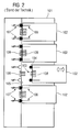
- plug-in modules 102 are provided, which are positionable in insertion slots 103.
- Each plug-in module 102 contains, for example, a motor branch.
- plug-in rails or plug-in connectors 106, 107 or other suitable connection elements are provided both on the rear sides 104 of the plug-in modules 102 and on the rear sides 105 of the plug-in ducts 103 formed by the rear wall of the motor switch cabinet 101 which cooperate in the assembled state.
- These connectors 106, 107 serve essentially for the transmission of main current (eg 400 V), for the transmission of auxiliary energy (control energy) for the supply of the devices and devices contained in the plug-in module.
- these connectors serve 106, 107 for the purpose of communication between the plug-in module 102 on the one hand and the insertion slot 103 and thus the motor control cabinet 101 on the other hand, in particular for the transmission of drive signals, feedback, error signals, etc., z. B. via a fieldbus system.
- cooperating plug-in rails or connectors 106, 107 are - as well as in the prior art - both on the backs 104 of the plug-in modules 102, and also provided on the rear sides 105 of the insertion shafts 103, cf. FIG. 3 ,
- the invention provides for the use of wireless communication to avoid the problems associated with conventional connectors 106, 107.
- the communication connectors are replaced by wireless-based wireless communication devices.
- the devices for wireless communication are on the one hand to the plug-in module 102 associated communication devices 111 for connection to a higher-level control, namely the control center of the motor control cabinet 101.
- the communication devices 111 are characterized in that they are for wireless communication with a suitably trained communication device 112 of the motor control cabinet 101 are formed.
- the communication devices 111 each comprise an antenna 113 and a transmitting and / or receiving unit 114.
- the antennas 113 are located on the rear sides 104 of the plug-in modules 102, while the transmitting and / or receiving units 114 can be placed anywhere within the plug-in modules 102 are.
- the devices for wireless communication are a communication device 112 of the motor control cabinet 101.
- This communication device 112 comprises a leaky waveguide 115, which is connected to a control center 116 serving as a transmitting / receiving unit.
- the communication between the plug-in module 102 associated communication device 111 and the communication device 112 of the motor control cabinet 101 is thus wireless.
- Leakage waveguides 115 are high-frequency conductors, usually at one end for the purpose of feeding with a base station, here the control unit 116, are connected, while their other end is completed with a reflection reflection. It may be in the classical sense to a waveguide with slots on the one hand. On the other hand, as a leaky waveguide 115, it is also possible to use specially machined coaxial cables which "lick" over their entire length. Preferably, within the scope of the embodiment of the invention described here, a so-called "RCoax Cable” from SIEMENS AG is used.
- radio systems are digital radio systems, such. B. WLAN and Bluetooth or TDMA systems in question.
- the feeding and operation of the leaky waveguide 115, as well as the connection to the control center 116 and the use of suitable transmission protocols, such as PROFIBUS or the like, are known in the art, so that it need not be discussed further here.
- the leaky waveguide 115 is arranged in the interior of the motor control cabinet 101, along the rear sides 105 of the insertion shafts 103. In the mounted state, the distance between the rear sides 105 of the insertion shafts 103 and the leaky waveguide 115 is only a few centimeters.
- encoder plug 108, 109 proposes the invention to use the possibility of wireless communication between the components for a wireless coding.
- the encoders 108, 109 are replaced by the wireless communication devices 111, 112 described above FIG. 3 , which can serve as a schematic representation for the description of this second embodiment of the invention.
- the communication devices 111, 112 are designed for this purpose for transmitting and / or receiving data that are relevant for the detection of the insertion slot 102 and / or the plug-in module 103.
- the communication devices 111, 112 are assigned both to the plug-in modules 102, as well as the insertion slots 103.
- the assignment takes place in this special case in such a way that the antennas of the communication devices 111, 112, here the antenna 113 on the one hand and the leaky waveguide 115 on the other hand, are fastened to the rear sides 104 of the plug-in modules 102 and to the rear sides 105 of the plug-in ducts 103 the control cabinet back is attached.
- a smallest possible distance between cooperating communication devices 111, 112 achieved in the mounted state, so that inter alia, the communication devices used to operate 111, 112 with low transmission power and only correspondingly small-sized transmit and receive devices.
- This not only allows a particularly compact design of the motor control cabinet 101. It also reduces the cost of materials for the communication devices 111, 112 and thus their production costs.
- the assignment of the communication devices 111, 112 to the components 102, 103 may, however, also be provided elsewhere. For example, it is not absolutely necessary for the communication devices 111, 112 to be connected directly to the components 102, 103. A loose allocation of the communication devices 111, 112 to the components 102, 103 is conceivable. For example, a receiver and / or transmitter may be loose in a plug-in module 102. As well A remote positioning of the communication devices 111, 112, even outside the components 102, 103, is conceivable. Such a remote positioning is possible insofar as an unambiguous assignment to a specific component 102, 103 is realized.
- the first communication device 111 assigned to the plug-in module 103 receives data relevant to identification, in particular a unique position identifier (slot ID), from the second communication device 112 assigned to the insertion slot 103, whereby both communication devices are self-powered ("active coding"). Subsequently, the first communication device 111 assigned to the plug-in module 102 transmits the received identification-relevant data to a local, ie dubbing, module 102 assigned to the plug-in module 102. H. formed as part of the plug-in module 102 release unit, which is designed as a data processing device. There, the processing of the identification-relevant data takes place with the aid of a computer program which is loaded for this purpose in the memory of the data processing device and is executed.
- slot ID unique position identifier
- the plug-in module 102 After checking the identification-relevant data, the plug-in module 102 is released for operation with the corresponding insertion slot 103, if such operation is permitted. Alternatively, the plug-in module 102 is disabled for such operation or remains disabled, depending on the default setting. It is particularly advantageous if the first communication device 111 sends a corresponding message in this case, preferably indicating the current installation location of the plug-in module 102, to an external receiver, for example to the control center of the motor control cabinet 101 or the like.
- the plug-in module 102 of the insertion slot 103 associated communication device 112 passed a corresponding address information, the enables localization of the plug-in module 102 in the motor control cabinet 101.
- the plug-in module 102 and / or the insertion slot 103 may be necessary before the release to modify the plug-in module 102 and / or the insertion slot 103, in particular the parameters for the transmission of main current, auxiliary power and communication (protocols, etc.).
- a communication-capable switchgear the changes required for this purpose are preferably made by the control center of the motor control cabinet 101.
Landscapes
- Engineering & Computer Science (AREA)
- Power Engineering (AREA)
- Near-Field Transmission Systems (AREA)
- Details Of Connecting Devices For Male And Female Coupling (AREA)
Priority Applications (1)
| Application Number | Priority Date | Filing Date | Title |
|---|---|---|---|
| EP07017246.5A EP2031626B1 (fr) | 2007-09-03 | 2007-09-03 | Dispositif de commutation à basse tension électrique |
Applications Claiming Priority (1)
| Application Number | Priority Date | Filing Date | Title |
|---|---|---|---|
| EP07017246.5A EP2031626B1 (fr) | 2007-09-03 | 2007-09-03 | Dispositif de commutation à basse tension électrique |
Publications (2)
| Publication Number | Publication Date |
|---|---|
| EP2031626A1 true EP2031626A1 (fr) | 2009-03-04 |
| EP2031626B1 EP2031626B1 (fr) | 2013-12-18 |
Family
ID=38917773
Family Applications (1)
| Application Number | Title | Priority Date | Filing Date |
|---|---|---|---|
| EP07017246.5A Not-in-force EP2031626B1 (fr) | 2007-09-03 | 2007-09-03 | Dispositif de commutation à basse tension électrique |
Country Status (1)
| Country | Link |
|---|---|
| EP (1) | EP2031626B1 (fr) |
Cited By (5)
| Publication number | Priority date | Publication date | Assignee | Title |
|---|---|---|---|---|
| WO2011038973A3 (fr) * | 2009-09-29 | 2012-01-26 | Siemens Aktiengesellschaft | Système pour installer des appareils immotiques |
| EP2525453A1 (fr) * | 2011-05-18 | 2012-11-21 | Siemens Aktiengesellschaft | Egalisation de paramètre d'un module d'introduction d'une installation de commutation à basse tension électrique |
| WO2012156207A1 (fr) * | 2011-05-18 | 2012-11-22 | Siemens Aktiengesellschaft | Appareil de commande et procédé permettant de faire fonctionner un tel appareil de commande |
| WO2014130289A1 (fr) * | 2013-02-19 | 2014-08-28 | Eaton Corporation | Centre de distribution comprenant un circuit de détection de position de disjoncteur |
| CN109074414A (zh) * | 2016-05-02 | 2018-12-21 | 维纳尔电气系统有限公司 | 用于配置配电箱的方法及系统 |
Citations (4)
| Publication number | Priority date | Publication date | Assignee | Title |
|---|---|---|---|---|
| DE10315646A1 (de) * | 2003-04-04 | 2004-11-11 | Abb Patent Gmbh | Schaltanlage und Verfahren zur Einschubebenenerkennung in einer Schaltanlage |
| EP1744487A1 (fr) * | 2005-07-13 | 2007-01-17 | ABB PATENT GmbH | Système modulaire pour l'alimentation d'énergie d'un dispositif entrée/sortie avant connecté plusieurs noeuds |
| DE202006000702U1 (de) * | 2005-12-12 | 2007-04-26 | Moeller Gmbh | Elektrisches Schaltgerät |
| DE202007006824U1 (de) | 2007-05-09 | 2007-07-12 | Weidmüller Interface GmbH & Co. KG | Schaltschrank für elektrische Geräte |
Family Cites Families (2)
| Publication number | Priority date | Publication date | Assignee | Title |
|---|---|---|---|---|
| GB9004917D0 (en) * | 1990-03-05 | 1990-05-02 | Hunting Eng Ltd | Systems employing leaky feeder communications |
| US7697946B2 (en) * | 2002-06-04 | 2010-04-13 | Forster Ian J | Reflective communication using radio-frequency devices |
-
2007
- 2007-09-03 EP EP07017246.5A patent/EP2031626B1/fr not_active Not-in-force
Patent Citations (4)
| Publication number | Priority date | Publication date | Assignee | Title |
|---|---|---|---|---|
| DE10315646A1 (de) * | 2003-04-04 | 2004-11-11 | Abb Patent Gmbh | Schaltanlage und Verfahren zur Einschubebenenerkennung in einer Schaltanlage |
| EP1744487A1 (fr) * | 2005-07-13 | 2007-01-17 | ABB PATENT GmbH | Système modulaire pour l'alimentation d'énergie d'un dispositif entrée/sortie avant connecté plusieurs noeuds |
| DE202006000702U1 (de) * | 2005-12-12 | 2007-04-26 | Moeller Gmbh | Elektrisches Schaltgerät |
| DE202007006824U1 (de) | 2007-05-09 | 2007-07-12 | Weidmüller Interface GmbH & Co. KG | Schaltschrank für elektrische Geräte |
Cited By (9)
| Publication number | Priority date | Publication date | Assignee | Title |
|---|---|---|---|---|
| WO2011038973A3 (fr) * | 2009-09-29 | 2012-01-26 | Siemens Aktiengesellschaft | Système pour installer des appareils immotiques |
| EP2525453A1 (fr) * | 2011-05-18 | 2012-11-21 | Siemens Aktiengesellschaft | Egalisation de paramètre d'un module d'introduction d'une installation de commutation à basse tension électrique |
| WO2012156207A1 (fr) * | 2011-05-18 | 2012-11-22 | Siemens Aktiengesellschaft | Appareil de commande et procédé permettant de faire fonctionner un tel appareil de commande |
| US10082809B2 (en) | 2011-05-18 | 2018-09-25 | Siemens Aktiengesellschaft | Control device and method for operating such a control device |
| WO2014130289A1 (fr) * | 2013-02-19 | 2014-08-28 | Eaton Corporation | Centre de distribution comprenant un circuit de détection de position de disjoncteur |
| CN109074414A (zh) * | 2016-05-02 | 2018-12-21 | 维纳尔电气系统有限公司 | 用于配置配电箱的方法及系统 |
| EP3452928B1 (fr) * | 2016-05-02 | 2021-03-31 | Wöhner GmbH & Co. KG Elektrotechnische Systeme | Procede et systeme de configuration d'une armoire electrique |
| US10998699B2 (en) | 2016-05-02 | 2021-05-04 | Woehner Gmbh & Co. | Method and system for configuring a switch cabinet |
| CN109074414B (zh) * | 2016-05-02 | 2023-06-20 | 维纳尔电气系统有限公司 | 用于配置配电箱的方法及系统 |
Also Published As
| Publication number | Publication date |
|---|---|
| EP2031626B1 (fr) | 2013-12-18 |
Similar Documents
| Publication | Publication Date | Title |
|---|---|---|
| EP2031625B1 (fr) | Procédé de reconnaissance de composants dans une installation de commutation à basse tension électrique | |
| EP0980603B1 (fr) | Connecteur male-femelle | |
| EP1885085B1 (fr) | Alimentation en énergie et en données sans contact pour des participants d un bus | |
| EP2031626B1 (fr) | Dispositif de commutation à basse tension électrique | |
| EP0344609A2 (fr) | Système de transmission numérique pour installations domestiques | |
| WO2018215289A1 (fr) | Unité de module permettant de connecter un abonné de bus de données | |
| DE10155481A1 (de) | Einrichtung zur Steuerung und Überwachung der Freigabe von Empfangssignalen an Anschlussstellen innerhalb von kabelgebundenen Hausverteilungsanlagen | |
| DE102019105171A1 (de) | IO-Link-Master, Schnittstelle und Verfahren zum Steuern und Überwachen eines IO-Link Systems | |
| EP1025327A1 (fr) | Systeme d'entrainement pour systeme de cloison | |
| WO2021121743A1 (fr) | Dispositif de transmission sans fil d'un signal | |
| EP2974548B1 (fr) | Dispositif d'éclairage avec deux interfaces | |
| EP2673157A2 (fr) | Dispositif de transmission d'énergie et de communication par induction | |
| EP3586201B1 (fr) | Adaptateur avant de connexion avec un dispositif de commande et système d'automatisation | |
| EP1800403B1 (fr) | Systeme de transmission de signaux servant a piloter au moins un commutateur statique de puissance et convertisseur muni d'un tel systeme de transmission de signaux | |
| EP3576508B1 (fr) | Module de raccordement pourvu d'interface optique permettant d'activer un émetteur / récepteur radio et procédé ainsi que procédé de fabrication correspondant | |
| DE102006014621A1 (de) | Elektrisches Gerät, Aufsteckteil und Verfahren zum Schalten einer Steckdose | |
| EP1677588B1 (fr) | Transferts optiques de données entre des appareils de montage et d'alimentation | |
| EP1062767A1 (fr) | Reseau informatique comportant des systemes terminaux de donnees et de communications | |
| EP0437696A1 (fr) | Dispositif de connexion commuable à distance | |
| EP2215615B1 (fr) | Dispositif et procédé pour la mise en réseau sans fil d'appareils utilisés en automatisation | |
| EP3441832A1 (fr) | Commande modulaire par programme enregistré | |
| EP1914927A1 (fr) | Coupleur de bus ainsi que système de communication doté d'un coupleur de bus | |
| EP0893745B2 (fr) | Module de communication | |
| EP1091331B1 (fr) | Poste d'abonné d'un système d'installation radio | |
| EP2802085B1 (fr) | Connecteur entre deux appareils de fabrication de produits alimentaires |
Legal Events
| Date | Code | Title | Description |
|---|---|---|---|
| PUAI | Public reference made under article 153(3) epc to a published international application that has entered the european phase |
Free format text: ORIGINAL CODE: 0009012 |
|
| AK | Designated contracting states |
Kind code of ref document: A1 Designated state(s): AT BE BG CH CY CZ DE DK EE ES FI FR GB GR HU IE IS IT LI LT LU LV MC MT NL PL PT RO SE SI SK TR |
|
| AX | Request for extension of the european patent |
Extension state: AL BA HR MK RS |
|
| 17P | Request for examination filed |
Effective date: 20090608 |
|
| AKX | Designation fees paid |
Designated state(s): AT BE BG CH CY CZ DE DK EE ES FI FR GB GR HU IE IS IT LI LT LU LV MC MT NL PL PT RO SE SI SK TR |
|
| 17Q | First examination report despatched |
Effective date: 20101125 |
|
| RAP1 | Party data changed (applicant data changed or rights of an application transferred) |
Owner name: SIEMENS AKTIENGESELLSCHAFT |
|
| GRAP | Despatch of communication of intention to grant a patent |
Free format text: ORIGINAL CODE: EPIDOSNIGR1 |
|
| INTG | Intention to grant announced |
Effective date: 20130708 |
|
| GRAS | Grant fee paid |
Free format text: ORIGINAL CODE: EPIDOSNIGR3 |
|
| GRAA | (expected) grant |
Free format text: ORIGINAL CODE: 0009210 |
|
| AK | Designated contracting states |
Kind code of ref document: B1 Designated state(s): AT BE BG CH CY CZ DE DK EE ES FI FR GB GR HU IE IS IT LI LT LU LV MC MT NL PL PT RO SE SI SK TR |
|
| REG | Reference to a national code |
Ref country code: GB Ref legal event code: FG4D Free format text: NOT ENGLISH |
|
| REG | Reference to a national code |
Ref country code: CH Ref legal event code: EP |
|
| REG | Reference to a national code |
Ref country code: AT Ref legal event code: REF Ref document number: 645934 Country of ref document: AT Kind code of ref document: T Effective date: 20140115 |
|
| REG | Reference to a national code |
Ref country code: IE Ref legal event code: FG4D Free format text: LANGUAGE OF EP DOCUMENT: GERMAN |
|
| REG | Reference to a national code |
Ref country code: DE Ref legal event code: R096 Ref document number: 502007012599 Country of ref document: DE Effective date: 20140213 |
|
| REG | Reference to a national code |
Ref country code: NL Ref legal event code: VDEP Effective date: 20131218 |
|
| PG25 | Lapsed in a contracting state [announced via postgrant information from national office to epo] |
Ref country code: FI Free format text: LAPSE BECAUSE OF FAILURE TO SUBMIT A TRANSLATION OF THE DESCRIPTION OR TO PAY THE FEE WITHIN THE PRESCRIBED TIME-LIMIT Effective date: 20131218 Ref country code: SE Free format text: LAPSE BECAUSE OF FAILURE TO SUBMIT A TRANSLATION OF THE DESCRIPTION OR TO PAY THE FEE WITHIN THE PRESCRIBED TIME-LIMIT Effective date: 20131218 Ref country code: LT Free format text: LAPSE BECAUSE OF FAILURE TO SUBMIT A TRANSLATION OF THE DESCRIPTION OR TO PAY THE FEE WITHIN THE PRESCRIBED TIME-LIMIT Effective date: 20131218 |
|
| REG | Reference to a national code |
Ref country code: LT Ref legal event code: MG4D |
|
| PG25 | Lapsed in a contracting state [announced via postgrant information from national office to epo] |
Ref country code: LV Free format text: LAPSE BECAUSE OF FAILURE TO SUBMIT A TRANSLATION OF THE DESCRIPTION OR TO PAY THE FEE WITHIN THE PRESCRIBED TIME-LIMIT Effective date: 20131218 |
|
| PG25 | Lapsed in a contracting state [announced via postgrant information from national office to epo] |
Ref country code: IS Free format text: LAPSE BECAUSE OF FAILURE TO SUBMIT A TRANSLATION OF THE DESCRIPTION OR TO PAY THE FEE WITHIN THE PRESCRIBED TIME-LIMIT Effective date: 20140418 Ref country code: EE Free format text: LAPSE BECAUSE OF FAILURE TO SUBMIT A TRANSLATION OF THE DESCRIPTION OR TO PAY THE FEE WITHIN THE PRESCRIBED TIME-LIMIT Effective date: 20131218 |
|
| PG25 | Lapsed in a contracting state [announced via postgrant information from national office to epo] |
Ref country code: PL Free format text: LAPSE BECAUSE OF FAILURE TO SUBMIT A TRANSLATION OF THE DESCRIPTION OR TO PAY THE FEE WITHIN THE PRESCRIBED TIME-LIMIT Effective date: 20131218 Ref country code: CZ Free format text: LAPSE BECAUSE OF FAILURE TO SUBMIT A TRANSLATION OF THE DESCRIPTION OR TO PAY THE FEE WITHIN THE PRESCRIBED TIME-LIMIT Effective date: 20131218 Ref country code: NL Free format text: LAPSE BECAUSE OF FAILURE TO SUBMIT A TRANSLATION OF THE DESCRIPTION OR TO PAY THE FEE WITHIN THE PRESCRIBED TIME-LIMIT Effective date: 20131218 Ref country code: CY Free format text: LAPSE BECAUSE OF FAILURE TO SUBMIT A TRANSLATION OF THE DESCRIPTION OR TO PAY THE FEE WITHIN THE PRESCRIBED TIME-LIMIT Effective date: 20131218 Ref country code: ES Free format text: LAPSE BECAUSE OF FAILURE TO SUBMIT A TRANSLATION OF THE DESCRIPTION OR TO PAY THE FEE WITHIN THE PRESCRIBED TIME-LIMIT Effective date: 20131218 Ref country code: PT Free format text: LAPSE BECAUSE OF FAILURE TO SUBMIT A TRANSLATION OF THE DESCRIPTION OR TO PAY THE FEE WITHIN THE PRESCRIBED TIME-LIMIT Effective date: 20140418 Ref country code: RO Free format text: LAPSE BECAUSE OF FAILURE TO SUBMIT A TRANSLATION OF THE DESCRIPTION OR TO PAY THE FEE WITHIN THE PRESCRIBED TIME-LIMIT Effective date: 20131218 Ref country code: SK Free format text: LAPSE BECAUSE OF FAILURE TO SUBMIT A TRANSLATION OF THE DESCRIPTION OR TO PAY THE FEE WITHIN THE PRESCRIBED TIME-LIMIT Effective date: 20131218 |
|
| REG | Reference to a national code |
Ref country code: DE Ref legal event code: R097 Ref document number: 502007012599 Country of ref document: DE |
|
| PLBE | No opposition filed within time limit |
Free format text: ORIGINAL CODE: 0009261 |
|
| STAA | Information on the status of an ep patent application or granted ep patent |
Free format text: STATUS: NO OPPOSITION FILED WITHIN TIME LIMIT |
|
| PG25 | Lapsed in a contracting state [announced via postgrant information from national office to epo] |
Ref country code: DK Free format text: LAPSE BECAUSE OF FAILURE TO SUBMIT A TRANSLATION OF THE DESCRIPTION OR TO PAY THE FEE WITHIN THE PRESCRIBED TIME-LIMIT Effective date: 20131218 |
|
| 26N | No opposition filed |
Effective date: 20140919 |
|
| REG | Reference to a national code |
Ref country code: DE Ref legal event code: R097 Ref document number: 502007012599 Country of ref document: DE Effective date: 20140919 |
|
| PG25 | Lapsed in a contracting state [announced via postgrant information from national office to epo] |
Ref country code: LU Free format text: LAPSE BECAUSE OF FAILURE TO SUBMIT A TRANSLATION OF THE DESCRIPTION OR TO PAY THE FEE WITHIN THE PRESCRIBED TIME-LIMIT Effective date: 20140903 Ref country code: MC Free format text: LAPSE BECAUSE OF FAILURE TO SUBMIT A TRANSLATION OF THE DESCRIPTION OR TO PAY THE FEE WITHIN THE PRESCRIBED TIME-LIMIT Effective date: 20131218 |
|
| REG | Reference to a national code |
Ref country code: CH Ref legal event code: PL |
|
| GBPC | Gb: european patent ceased through non-payment of renewal fee |
Effective date: 20140903 |
|
| PG25 | Lapsed in a contracting state [announced via postgrant information from national office to epo] |
Ref country code: SI Free format text: LAPSE BECAUSE OF FAILURE TO SUBMIT A TRANSLATION OF THE DESCRIPTION OR TO PAY THE FEE WITHIN THE PRESCRIBED TIME-LIMIT Effective date: 20131218 |
|
| REG | Reference to a national code |
Ref country code: IE Ref legal event code: MM4A |
|
| PG25 | Lapsed in a contracting state [announced via postgrant information from national office to epo] |
Ref country code: BE Free format text: LAPSE BECAUSE OF NON-PAYMENT OF DUE FEES Effective date: 20140930 |
|
| PG25 | Lapsed in a contracting state [announced via postgrant information from national office to epo] |
Ref country code: GB Free format text: LAPSE BECAUSE OF NON-PAYMENT OF DUE FEES Effective date: 20140903 Ref country code: LI Free format text: LAPSE BECAUSE OF NON-PAYMENT OF DUE FEES Effective date: 20140930 Ref country code: CH Free format text: LAPSE BECAUSE OF NON-PAYMENT OF DUE FEES Effective date: 20140930 |
|
| PG25 | Lapsed in a contracting state [announced via postgrant information from national office to epo] |
Ref country code: IE Free format text: LAPSE BECAUSE OF NON-PAYMENT OF DUE FEES Effective date: 20140903 |
|
| REG | Reference to a national code |
Ref country code: AT Ref legal event code: MM01 Ref document number: 645934 Country of ref document: AT Kind code of ref document: T Effective date: 20140903 |
|
| PG25 | Lapsed in a contracting state [announced via postgrant information from national office to epo] |
Ref country code: AT Free format text: LAPSE BECAUSE OF NON-PAYMENT OF DUE FEES Effective date: 20140903 |
|
| PG25 | Lapsed in a contracting state [announced via postgrant information from national office to epo] |
Ref country code: BG Free format text: LAPSE BECAUSE OF FAILURE TO SUBMIT A TRANSLATION OF THE DESCRIPTION OR TO PAY THE FEE WITHIN THE PRESCRIBED TIME-LIMIT Effective date: 20131218 |
|
| PG25 | Lapsed in a contracting state [announced via postgrant information from national office to epo] |
Ref country code: MT Free format text: LAPSE BECAUSE OF FAILURE TO SUBMIT A TRANSLATION OF THE DESCRIPTION OR TO PAY THE FEE WITHIN THE PRESCRIBED TIME-LIMIT Effective date: 20131218 Ref country code: GR Free format text: LAPSE BECAUSE OF FAILURE TO SUBMIT A TRANSLATION OF THE DESCRIPTION OR TO PAY THE FEE WITHIN THE PRESCRIBED TIME-LIMIT Effective date: 20140319 |
|
| PG25 | Lapsed in a contracting state [announced via postgrant information from national office to epo] |
Ref country code: TR Free format text: LAPSE BECAUSE OF FAILURE TO SUBMIT A TRANSLATION OF THE DESCRIPTION OR TO PAY THE FEE WITHIN THE PRESCRIBED TIME-LIMIT Effective date: 20131218 Ref country code: HU Free format text: LAPSE BECAUSE OF FAILURE TO SUBMIT A TRANSLATION OF THE DESCRIPTION OR TO PAY THE FEE WITHIN THE PRESCRIBED TIME-LIMIT; INVALID AB INITIO Effective date: 20070903 |
|
| REG | Reference to a national code |
Ref country code: FR Ref legal event code: PLFP Year of fee payment: 10 |
|
| REG | Reference to a national code |
Ref country code: FR Ref legal event code: PLFP Year of fee payment: 11 |
|
| REG | Reference to a national code |
Ref country code: FR Ref legal event code: PLFP Year of fee payment: 12 |
|
| PGFP | Annual fee paid to national office [announced via postgrant information from national office to epo] |
Ref country code: FR Payment date: 20190918 Year of fee payment: 13 |
|
| PGFP | Annual fee paid to national office [announced via postgrant information from national office to epo] |
Ref country code: DE Payment date: 20191119 Year of fee payment: 13 |
|
| PGFP | Annual fee paid to national office [announced via postgrant information from national office to epo] |
Ref country code: IT Payment date: 20190926 Year of fee payment: 13 |
|
| REG | Reference to a national code |
Ref country code: DE Ref legal event code: R119 Ref document number: 502007012599 Country of ref document: DE |
|
| PG25 | Lapsed in a contracting state [announced via postgrant information from national office to epo] |
Ref country code: FR Free format text: LAPSE BECAUSE OF NON-PAYMENT OF DUE FEES Effective date: 20200930 Ref country code: DE Free format text: LAPSE BECAUSE OF NON-PAYMENT OF DUE FEES Effective date: 20210401 |
|
| PG25 | Lapsed in a contracting state [announced via postgrant information from national office to epo] |
Ref country code: IT Free format text: LAPSE BECAUSE OF NON-PAYMENT OF DUE FEES Effective date: 20200903 |