EP2802085B1 - Connecteur entre deux appareils de fabrication de produits alimentaires - Google Patents
Connecteur entre deux appareils de fabrication de produits alimentaires Download PDFInfo
- Publication number
- EP2802085B1 EP2802085B1 EP13167222.2A EP13167222A EP2802085B1 EP 2802085 B1 EP2802085 B1 EP 2802085B1 EP 13167222 A EP13167222 A EP 13167222A EP 2802085 B1 EP2802085 B1 EP 2802085B1
- Authority
- EP
- European Patent Office
- Prior art keywords
- data transmission
- connecting element
- transmission part
- filling line
- line according
- Prior art date
- Legal status (The legal status is an assumption and is not a legal conclusion. Google has not performed a legal analysis and makes no representation as to the accuracy of the status listed.)
- Active
Links
- 238000004519 manufacturing process Methods 0.000 title claims description 11
- 235000013305 food Nutrition 0.000 title description 7
- 230000005540 biological transmission Effects 0.000 claims description 97
- 239000003990 capacitor Substances 0.000 claims description 40
- 235000013580 sausages Nutrition 0.000 claims description 16
- 239000000463 material Substances 0.000 claims description 8
- 238000000926 separation method Methods 0.000 claims description 7
- 230000003287 optical effect Effects 0.000 claims description 5
- 230000008878 coupling Effects 0.000 claims description 4
- 238000010168 coupling process Methods 0.000 claims description 4
- 238000005859 coupling reaction Methods 0.000 claims description 4
- 208000019300 CLIPPERS Diseases 0.000 claims description 3
- 208000021930 chronic lymphocytic inflammation with pontine perivascular enhancement responsive to steroids Diseases 0.000 claims description 3
- 229920003002 synthetic resin Polymers 0.000 claims description 2
- 239000000057 synthetic resin Substances 0.000 claims description 2
- 238000012856 packing Methods 0.000 claims 1
- 229920005992 thermoplastic resin Polymers 0.000 claims 1
- 239000004416 thermosoftening plastic Substances 0.000 claims 1
- 238000000034 method Methods 0.000 description 11
- 230000008569 process Effects 0.000 description 6
- 230000005684 electric field Effects 0.000 description 5
- 239000010410 layer Substances 0.000 description 5
- 235000013372 meat Nutrition 0.000 description 5
- 238000012546 transfer Methods 0.000 description 5
- 239000012815 thermoplastic material Substances 0.000 description 4
- 229920000178 Acrylic resin Polymers 0.000 description 3
- 239000004925 Acrylic resin Substances 0.000 description 3
- 230000001939 inductive effect Effects 0.000 description 3
- 238000005304 joining Methods 0.000 description 3
- 239000011241 protective layer Substances 0.000 description 3
- 229920005989 resin Polymers 0.000 description 3
- 239000011347 resin Substances 0.000 description 3
- 239000004952 Polyamide Substances 0.000 description 2
- 239000004698 Polyethylene Substances 0.000 description 2
- 230000008901 benefit Effects 0.000 description 2
- 238000004140 cleaning Methods 0.000 description 2
- 230000001427 coherent effect Effects 0.000 description 2
- 239000004020 conductor Substances 0.000 description 2
- 230000007797 corrosion Effects 0.000 description 2
- 238000005260 corrosion Methods 0.000 description 2
- 239000003822 epoxy resin Substances 0.000 description 2
- 239000000945 filler Substances 0.000 description 2
- 238000002955 isolation Methods 0.000 description 2
- 229920002647 polyamide Polymers 0.000 description 2
- 229920000647 polyepoxide Polymers 0.000 description 2
- 229920000728 polyester Polymers 0.000 description 2
- 229920001225 polyester resin Polymers 0.000 description 2
- 239000004645 polyester resin Substances 0.000 description 2
- -1 polyethylene Polymers 0.000 description 2
- 229920000573 polyethylene Polymers 0.000 description 2
- 229920002635 polyurethane Polymers 0.000 description 2
- 239000004814 polyurethane Substances 0.000 description 2
- 238000004382 potting Methods 0.000 description 2
- 229920002050 silicone resin Polymers 0.000 description 2
- 229920001567 vinyl ester resin Polymers 0.000 description 2
- 238000004804 winding Methods 0.000 description 2
- 230000008859 change Effects 0.000 description 1
- 239000011248 coating agent Substances 0.000 description 1
- 238000000576 coating method Methods 0.000 description 1
- 238000004891 communication Methods 0.000 description 1
- 150000001875 compounds Chemical class 0.000 description 1
- 238000010276 construction Methods 0.000 description 1
- 238000013461 design Methods 0.000 description 1
- 238000001514 detection method Methods 0.000 description 1
- 238000010586 diagram Methods 0.000 description 1
- 238000009826 distribution Methods 0.000 description 1
- 239000000835 fiber Substances 0.000 description 1
- 239000011152 fibreglass Substances 0.000 description 1
- 239000011888 foil Substances 0.000 description 1
- 230000010354 integration Effects 0.000 description 1
- 239000004922 lacquer Substances 0.000 description 1
- 230000002045 lasting effect Effects 0.000 description 1
- 230000007257 malfunction Effects 0.000 description 1
- 230000003647 oxidation Effects 0.000 description 1
- 238000007254 oxidation reaction Methods 0.000 description 1
- 238000004806 packaging method and process Methods 0.000 description 1
- 235000011837 pasties Nutrition 0.000 description 1
- 238000002360 preparation method Methods 0.000 description 1
- 238000012545 processing Methods 0.000 description 1
- 230000001681 protective effect Effects 0.000 description 1
- 239000000126 substance Substances 0.000 description 1
- 230000002123 temporal effect Effects 0.000 description 1
- 230000007704 transition Effects 0.000 description 1
- XLYOFNOQVPJJNP-UHFFFAOYSA-N water Substances O XLYOFNOQVPJJNP-UHFFFAOYSA-N 0.000 description 1
Images


Classifications
-
- H—ELECTRICITY
- H04—ELECTRIC COMMUNICATION TECHNIQUE
- H04B—TRANSMISSION
- H04B5/00—Near-field transmission systems, e.g. inductive or capacitive transmission systems
- H04B5/20—Near-field transmission systems, e.g. inductive or capacitive transmission systems characterised by the transmission technique; characterised by the transmission medium
- H04B5/22—Capacitive coupling
-
- A—HUMAN NECESSITIES
- A22—BUTCHERING; MEAT TREATMENT; PROCESSING POULTRY OR FISH
- A22C—PROCESSING MEAT, POULTRY, OR FISH
- A22C7/00—Apparatus for pounding, forming, or pressing meat, sausage-meat, or meat products
-
- H—ELECTRICITY
- H01—ELECTRIC ELEMENTS
- H01F—MAGNETS; INDUCTANCES; TRANSFORMERS; SELECTION OF MATERIALS FOR THEIR MAGNETIC PROPERTIES
- H01F38/00—Adaptations of transformers or inductances for specific applications or functions
- H01F38/14—Inductive couplings
-
- H—ELECTRICITY
- H04—ELECTRIC COMMUNICATION TECHNIQUE
- H04B—TRANSMISSION
- H04B5/00—Near-field transmission systems, e.g. inductive or capacitive transmission systems
- H04B5/20—Near-field transmission systems, e.g. inductive or capacitive transmission systems characterised by the transmission technique; characterised by the transmission medium
- H04B5/24—Inductive coupling
-
- H—ELECTRICITY
- H04—ELECTRIC COMMUNICATION TECHNIQUE
- H04B—TRANSMISSION
- H04B5/00—Near-field transmission systems, e.g. inductive or capacitive transmission systems
- H04B5/70—Near-field transmission systems, e.g. inductive or capacitive transmission systems specially adapted for specific purposes
- H04B5/72—Near-field transmission systems, e.g. inductive or capacitive transmission systems specially adapted for specific purposes for local intradevice communication
-
- H—ELECTRICITY
- H04—ELECTRIC COMMUNICATION TECHNIQUE
- H04B—TRANSMISSION
- H04B5/00—Near-field transmission systems, e.g. inductive or capacitive transmission systems
- H04B5/70—Near-field transmission systems, e.g. inductive or capacitive transmission systems specially adapted for specific purposes
- H04B5/75—Near-field transmission systems, e.g. inductive or capacitive transmission systems specially adapted for specific purposes for isolation purposes
-
- A—HUMAN NECESSITIES
- A22—BUTCHERING; MEAT TREATMENT; PROCESSING POULTRY OR FISH
- A22C—PROCESSING MEAT, POULTRY, OR FISH
- A22C11/00—Sausage making ; Apparatus for handling or conveying sausage products during manufacture
Definitions
- the present invention relates to a filling machine with a connector for data transmission, eg for Ethernet-based fieldbus systems, at an interface between two devices, in particular for process data transmission between two devices for food production, especially of meat and sausages.
- a connector for data transmission eg for Ethernet-based fieldbus systems
- process data transmission for Ethernet-based fieldbus systems conventional cables and connectors are used, such as in the Fig. 17 is shown. Cables and connectors often cause malfunctions, downtime and failures on machines in harsh environments.
- the connector pin and the associated socket contact are particularly susceptible to mechanical damage, soiling and corrosion when unplugged. With most of the connectors available on the market, even unplugged water or cleaning chemicals can penetrate through the connector into the cable and cause lasting damage due to corrosion. The transition from the plug pin or socket contact to the cable is also highly susceptible to oxidation because of the different materials. This then leads to high contact resistance and leakage currents.
- Bus subscribers are, for example, logic units, signal units, counting units, small controllers. These units are also referred to as a device and are relatively small in size and housed, for example, in cabinets. The communication between individual units can be implemented galvanically isolated.
- the EP 2 073 315 A2 also describes a device for electrically isolated coupling of multiple bus participants, which are releasably attached to a mounting rail.
- the publication US 5,572,441 shows a connector with a cable having a first and second connecting element, wherein the connection is capacitive.
- the connector couples laptop computer with stationary devices.
- the document EP-A-1312264 discloses a device for making sausages.
- the present invention has the object, a filling line with a connector for data transmission, in particular between two food processing equipment, especially meat and sausage products to provide that allow reliable data transmission in real time and beyond can be made robust, so they can withstand the harsh environment that prevails in food production in particular.
- the connector for data transmission at an interface between two food preparation devices, especially meat and sausages a first connection element which is connectable to the first device and at least a first data transmission part and a second with the first connection element couplable connecting element which can be connected to the second device and has at least one second data transmission part.
- the first data transmission part is galvanically isolated from the second data transmission part in the coupled state of the first and second connection element, such that the data transmission from the first connection element to the second connection element is galvanically separated, that is to say wireless and contactless.
- various components such as transformers, capacitors, optocouplers, antennas, directional antennas, optical transmitters and receivers, etc. can be used.
- the present invention has the advantage that now compared to conventional plugs no connector pins or socket contacts are more necessary, which are very susceptible to interference. Faults, stoppages and failures can be minimized. It is also advantageous that in the galvanically separated data transmission and the integration of the data transmission part in a connecting element, e.g. a housing of a connecting element, for data transmission no more open metallic contacts are more necessary.
- a connecting element e.g. a housing of a connecting element
- the connector according to the invention is very robust in terms of dirt and moisture, so that the contact problems described above can be avoided.
- the connector according to the invention also enables data transmission in real time.
- the connector comprises a mechanical fastening device, which couples the first connecting element, in particular its housing, with the second connecting element, in particular its housing.
- the mechanical fastening device may in particular comprise a screw cap, a plug connection, a bayonet closure, a clamp closure or permanent magnets.
- the fastening device hermetically seals the connecting elements or their housing, so that the data transmission parts in the connected first and second connecting element are protected against moisture and dirt, even if parts of the data transmission parts are exposed in the connecting element.
- first and second data transmission parts are already hermetically sealed in the first and second connection elements. Then, the data transmission parts are sufficiently protected from moisture, dirt and mechanical damage even when the connector is in the opened state.
- the first or second or both data transmission parts may be cast in a jacket material.
- the jacket material is preferably electrically insulating.
- thermoplastic material such as polyamide, polyester or polyethylene. But also one or two-component potting z. Example, epoxy resin, polyester resin, vinyl ester resin, polyurethane, silicone resin, acrylic resin, optionally with fillers, such as. As fiber, is possible.
- the first connection element may comprise as a data transmission part a primary coil and the second connection element as data transmission part a secondary coil, such that the data is transmitted inductively.
- a transformer is produced which comprises the primary coil and the secondary coil.
- the cores of the coils may be formed semi-annular, such that when joining the connecting elements, the end faces are opposite, wherein optionally still a protective layer is disposed over the end faces of the core.
- Under poured means that the respective data transmission part is either completely encapsulated and enclosed or that, for example, portions such as a capacitor electrode or a portion of the coil core is exposed, then corresponding sections may optionally be coated with a protective layer.
- the primary coil and the secondary coil each correspond to one half of a transformer whose core, in particular ring core, is in two parts, such that the respective end faces of the separate cores of the primary and secondary coils are aligned with each other in the coupled state of the first and second connection elements and preferably lie against each other. If the primary coil and secondary coil are constructed accordingly, the manufacture of the connector is very simple.
- the first connection element and the second connection element may be designed such that the data is transmitted capacitively, wherein the first connection element comprises at least two first capacitor electrodes as data transmission part and the second connection element as data transmission part at least two second capacitor electrodes, wherein the first and second capacitor electrode in the coupled state of the connecting elements opposite.
- capacitors for line disconnection are readily possible.
- the information is passed through an electric field.
- a capacitor can be constructed from two insulated electrodes to create a hermetically sealed separation point. Another pouring of the respective capacitor electrodes is also possible.
- the capacitor electrodes are again at a small distance from z. B. 1 mm aligned with each other, so that the electric field is closed again and the information can thus be transmitted freely.
- a plurality of capacitor electrodes are arranged flat, in particular as flat rings on a carrier, in particular a cylinder.
- the second connecting element is then designed as a sleeve, which has a plurality of flat, in particular formed as a flat ring capacitor electrodes.
- the first capacitor electrodes are opposite the second capacitor electrodes.
- the data transmission via electromagnetic waves wherein in particular the first connection element comprises a transmitter as data transmission part and the second connection part comprises as data transmission part a receiver.
- transmitter and receiver antennas can be used as transmitters and receivers, for example, or else combined transmitter-receiver antennas. These antennas are suitable for radio transmission for frequencies from 2 - 100 GHz.
- the optical transmitter for example, a light emitting diode (LED) or laser diode and be the optical receiver, for example, a phototransistor or a PIN diode.
- the first and second connecting element each have a plurality of data transmission parts for a plurality of transmission paths, in particular a plurality of coils, a plurality Capacitor electrodes, multiple transmitters or receivers.
- the connector may also include a path for energy transfer.
- the connector enables a wireless and contactless transmission of data.
- the first and second devices are at least two devices from the following group: filling machine, twisting unit, clipper, trailer, compartment element, conveyor belt, handling device, packaging unit.
- filling machine twisting unit
- clipper clipper
- trailer compartment element
- conveyor belt handling device
- packaging unit packaging unit
- At least one of the connecting elements or else both will be connected by a cable to a corresponding device.
- a connecting element in the device as a connection interface.
- the cables can be hermetically sealed to the connecting elements or their housings.
- the invention relates to a filling line for sausage production with multiple devices, i. with at least in addition a header as previously described. At least two devices of the entire filling line are then connected to a connector according to the invention.
- the first and second connecting element are first connected to one another with the mechanical fastening device, wherein the data transmission then takes place galvanically separated from the first to the second connector, ie for example, inductive, capacitive, optical or electromagnetic waves.
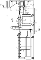
- Fig. 1 shows a schematic representation of a filling machine 11 with multiple attachments.
- the filling machine 11 has, in a known manner, a funnel 12 into which, for example, pasty mass, such as sausage meat, is filled and is discharged through a filling tube 13 into a sausage casing via an unillustrated conveyor.
- the transport device can also keep the filled sausage strand from twisting when the filled sausage strand is rotated by a twisting unit 17 in order to produce a twist-off point.
- a clipper 16 can also be arranged in the line for setting a clip between two sausage portions.
- a trailer 18 is arranged, which can receive individual sausages or sausage portions on its hooks 19 and further transport.
- Fig. 1 construction shown is just one example. Individual devices of a filling line can be interconnected with mechanical connectors 20.
- cables 8 are provided, which are connected to the connectors 1 according to the invention, as will be described in more detail below.
- the hanger 18 is connected to the controller of the filling machine 11 via the cable 8 with a connector 1.
- the transport device 14 is connected via a cable 8 with a corresponding connector 1 with the control of the filling machine.
- the transport device could also be connected to the trailer 8 via a cable by means of a connector 1.
- a connector system for data transmission at an interface between two devices is proposed for a corresponding filling machine or a corresponding filling line, which can be constructed as follows.
- the connector 1 as in particular Fig. 5 it can be seen, a first connection element 2a on and a second connection element 2b, which can be coupled to each other for the connection of the data lines, as was the case in the case of conventional plugs earlier.
- the connecting elements have data transmission parts 3a and 3b, wherein these data transmission parts are designed such that in the coupled or connected state of the first and second connecting element, the data transmission parts 3a, b are electrically isolated (ie, contactless).
- the galvanic Separation by two electrically isolated windings and the data transmission is carried out inductively.
- the first connection element 2a as a data transmission part has a primary coil 3a, which comprises a core 7a.
- the core 7 is curved and has two end faces 9, which may face an opposite connecting element.
- the second connection element 2b has a corresponding secondary coil 3b.
- the two coil halves When assembling the primary and secondary coils, i. when coupling the first and second connection elements, the two coil halves then function like a network transmitter.
- Ethernet standards according to IEEE 802.3 can be used.
- the invention is therefore based on the following consideration.
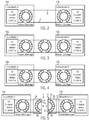
- Fig. 2 shows in eg Ethernet-based transmission links on both the transmitter and on the receiver side for electrical isolation, a transformer (transformer) is used. From the transmitter, the information is passed through a magnetic field.
- Fig. 2 shows a network card A of a first device 10a and a network card B of a second device 10b, wherein each network interface controller are provided.
- the network cards have conventional network transmitters as described above. Via cables or cables 8, the network transmitters of the devices 10a, b can be connected to each other.
- an additional transformer can be easily inserted into the route, as in Fig. 3 is shown.
- the additional transformer can be split into two halves and cut open, as in Fig. 4 is shown.
- the magnetic field After joining the separation point, the magnetic field is closed again and the information can be transmitted freely.
- the data transmission part 3a, b can thus be easily generated by a conventional, for example, the Ethernet standard sufficient transformer is separated into two parts or a transformer is composed of two half-cores.
- the primary and secondary coils can be in a jacket material, for.
- a jacket material for.
- the coils are completely cast in such a way that a thin layer is formed on the end face 9 of the cores 7a, b is. However, this layer should not be thicker than 0.2 mm to ensure proper data transmission.
- the coils 3a, b can be cast in such a way that the end faces 9 of the cores 7a, b are exposed. Then, when connecting the connecting elements, the front side of the cores can be exactly brought together. The windings of the coil are nevertheless sufficiently protected in the opened state from moisture and dirt.
- the exposed end faces 9 of the cores 7a, b by a thin coating on the connector front side (which faces the opposite connecting element).
- a thin layer for example, a film having a thickness of 20 .mu.m to 300 .mu.m can be used.
- the coils, ie the wound conductor wires, are hermetically sealed in the connecting elements.
- the connecting elements 2a, b have a mechanical fastening device 4, via which the first connecting element 2a can be coupled to the second connecting element 2b, for example schematically in FIG Fig. 5 is indicated.
- a mechanical fastening device may comprise, for example, a screw cap, a plug connection, a bayonet closure, a clamping device or permanent magnets. It is particularly advantageous if the fastening device 4 is designed such that a hermetically sealed connection between the connecting elements 2a, b is formed. This brings additional protection.
- Fig. 6 shows now roughly schematically each two transmit and receive channels between the network cards A and B with a total of 4 transformers or 8 transformer halves.
- the plurality of transmitter halves or coils, such as in Fig. 7 is aligned so aligned on the male front surface that the stray magnetic fields do not affect each other.
- Fig. 7 shows two juxtaposed first primary coils 3a1, 3a2, which are arranged perpendicular to each other.
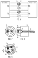
- Fig. 8 shows a longitudinal section of a corresponding embodiment with two mutually perpendicular coils 3a1 and 3a2, which are each connected to the corresponding signal lines 23 and open into a cable 8.
- the signal lines 23 and the cable 8 are also cast in the connecting element 2a.
- Fig. 9 shows a front view of a connecting element 2a with four primary coils, wherein the distance of two coils which are aligned at the same angle, is greater than the distance from two coils which are offset by approximately 90 ° to each other. This arrangement results in a compact design with little mutual interference.
- the corresponding second connecting elements 2b are then formed so that the respective end faces 9 of the individual cores 7 are opposite when the connecting elements 2a, b are connected.
- a transformer with the following characteristics is used as the basis for the connector: Inductance 350 ⁇ H at 100 kHz, 100 mV AC, 8 mA DC, turn ratio 1: 1.
- the distance a between two coils, which are aligned in substantially the same direction, ie parallel to each other, should be in a range of 5 to 10 mm.
- the distance b between two coils that are substantially perpendicular to each other should be in a range of 2 to 5 mm.
- This embodiment has the advantage that it is not necessary to use a special protocol that controls addressing, frequency change, repetition or collision detection. Also, no special modulation method is needed. Real-time data transmission is possible.
- Ethernet-based transmission links Because at e.g. Ethernet-based transmission links, the information can be transmitted differentially without reference to DC voltage, can be easily inserted capacitors for line separation.
- a capacitor In the capacitor, the information is passed through an electric field.
- a capacitor can be made by two electrically insulated electrodes to create a hermetically sealed separation point. By approaching the two electrodes, the electric field is closed and the information can be transmitted freely, as will be explained in more detail below.
- the capacitor electrodes can each be completely embedded in an electrically insulating sheath material, in particular cast, such as in synthetic resin or a thermoplastic material.
- the 10 to 12 make it clear that between two network transmitters, a capacitor can be interposed, in which case the two data transmission parts can be obtained by simply separating the capacitor.
- Fig. 14 shows two network cards A, B of two different devices roughly schematically each with a transmitting and a receiving channel, the transmitting and receiving channel each having two capacitors C1, C2 and C3, C4.
- Fig. 15 shows a specific embodiment of the capacitive data transmission.
- the illustrated capacitors C1 to C4 are here applied, for example, as flat rings on a cylinder.
- the electrode surfaces are connected to corresponding signal lines 23 extending inside the cylinder.
- a protective layer for example in the form of a film, a heat shrink tubing or protective lacquer.
- the connecting element 2a is provided, which is designed as a sleeve, such that the connecting element 2b can be at least partially inserted into this sleeve 2a, wherein the diameter d 2 is greater than the diameter d 1 .
- annular capacitor electrodes of the capacitors C1 to C4 are mounted, wherein in the coupled state of the connecting elements 2a, b, the electrodes of the sleeve are spaced from each other.
- the connector has a mechanical fastening device, which is indicated by 5, for example, a connector through which the sleeve can be aligned to the cylinder and over which a hermetically sealed connection can be made.
- the capacitor electrode surfaces of the sleeve may also be coated for protection, for example with a 50 ⁇ m to 200 ⁇ m thick foil or insulating layer.
- the cable 8 are cast into the connecting elements 2a, b.
- the capacitance of the capacitor is suitably 5 nF to 50 nF.
- Fig. 16 shows a further embodiment of the present invention, wherein the data is transmitted here via electromagnetic waves.
- the in Fig. 16 The structure shown corresponds to the structure of the previous embodiments, in which case a transmitter 3a and a receiver 3b is used as the data transmission part.
- a radio transmission frequency range 2 GHz to 100 GHz
- corresponding antennas (transmitter and / or receiver antennas) 3a, b are used.
- the distance I between the antennas in a closed state of the connector is in a range of 1 mm to 20 mm.
- the antennas are integrated in the first and second connection elements.
- the antennas 3a, b can be cast in the connecting element, which ensures additional protection.
- the fastening device can connect the two connecting elements hermetically sealed. Due to the small distance between the antennas 3a, b and the correct constant alignment of the antennas, an exact data transmission can be realized.
- the fact that the antennas are arranged in the connecting element, in particular housing, can also be realized a shield to the outside, for example, by externally attached to the connecting element 2a, a grounded conductive layer.
- the entire connecting element may be made of conductive material.
- the antennas are cast in, as a jacket material should be a thermoplastic material, such. As polyamide, polyester or polyethylene can be used. But also one- or two-component potting compound, such. Example, epoxy resin, polyester resin, vinyl ester resin, polyurethane, silicone resin, acrylic resin, optionally with fillers, such as. As fiberglass is suitable.
- the cable 8 can be poured into the fasteners. The signal lines lead, as from the Fig. 16 then, for example, to a WLAN transmitter and receiver connected to a network interface controller.
- Fig. 16 shown arrangement can be used not only with radio, but also with preferably coherent light for data transmission (wavelength 400 nm - 1000 nm).
- an optocoupler is connected to the respective network interface controllers, wherein instead of the antenna 3a as a transmitter, for example, a laser diode is used and as a receiver 3b, a photodetector, in particular a phototransistor or a PIN diode is used.
- the data transmission parts 3a, b are then either not cast or in a transparent medium, such as acrylic resin.
- the operating voltage can be transmitted via robust contacts, while the transmission of the process data by means of the contactless devices or methods according to the invention works. It can, for example, a data transfer capacitive and an energy transfer inductively or vice versa.
- a combination of different wireless, so galvanic separated transmission methods, as shown in the various embodiments, is also possible.
- the connecting elements can be connected via cables 8 with the respective devices.
- one of the connecting elements is integrated in one device, to which then the further connecting element is "infected".
- first the first and second connection elements 2a, b are connected to one another via the fastening device 4, e.g. nested, screwed, etc. Then, a data transfer from the first to the second connection element can be done galvanically isolated, i. contactless and wireless.
Landscapes
- Engineering & Computer Science (AREA)
- Computer Networks & Wireless Communication (AREA)
- Signal Processing (AREA)
- Life Sciences & Earth Sciences (AREA)
- Power Engineering (AREA)
- Food Science & Technology (AREA)
- Zoology (AREA)
- Wood Science & Technology (AREA)
- Near-Field Transmission Systems (AREA)
- Details Of Connecting Devices For Male And Female Coupling (AREA)
- Processing Of Meat And Fish (AREA)
- Cable Transmission Systems, Equalization Of Radio And Reduction Of Echo (AREA)
- Arrangements For Transmission Of Measured Signals (AREA)
Claims (10)
- Ligne de remplissage pour la fabrication de saucisses, comprenant plusieurs appareillages (10a,b), au moins deux appareillages de la ligne de remplissage étant reliés à l'aide d'un connecteur de liaison pour la transmission de données en temps réel, le premier et le deuxième appareillage (10a,b) étant deux appareillages parmi ceux du groupe suivant :machine de remplissage, unité de torsion, appareil à clipper, appareillage de suspension, élément de subdivision, bande transporteuse, appareillage de manutention, unité d'emballage,et le connecteur de liaison (1) comprenant :un premier élément de connecteur de liaison (2a), qui peut être relié au premier appareillage (10a) et présente au moins une première partie de transmission de données (3a), etun deuxième élément de connecteur de liaison (2b) pouvant être couplé au premier élément de connecteur de liaison, et qui peut être relié au deuxième appareillage (10b) et présente au moins une deuxième partie de transmission de données (3b),ligne de remplissage dans laquelle, dans l'état couplé du premier et du deuxième élément de connecteur de liaison (2a,b), la première partie de transmission de données (3a) est isolée galvaniquement de la deuxième partie de transmission de données (3b), et au moins l'un des éléments de connecteur de liaison (2a,b) ou bien les deux, est relié ou sont reliés par l'intermédiaire d'un câble (8) à un appareillage (10a,b).
- Ligne de remplissage selon la revendication 1, caractérisée en ce que le connecteur de liaison (1) comprend un dispositif de fixation mécanique (4), qui assure le couplage, notamment de manière hermétiquement étanche, du premier élément de connecteur de liaison (2a) avec le deuxième élément de connecteur de liaison (2), le dispositif de fixation mécanique (4) comprenant notamment un verrouillage à vis ou une liaison par emboitement, ou encore un verrouillage à baïonnette ou un verrouillage par serrage ou un couplage au moyen d'un aimant permanent.
- Ligne de remplissage selon l'une au moins des revendications précédentes, caractérisée en ce que la première et la deuxième partie de transmission de données (3a,b) sont agencées, de manière hermétiquement étanche, respectivement dans le premier et le deuxième élément de connecteur de liaison (2a,b).
- Ligne de remplissage selon l'une au moins des revendications précédentes, caractérisée en ce que la première et la deuxième partie de transmission de données (3a,b) sont noyées par moulage dans un matériau d'enveloppe, notamment une matière plastique thermoplastique ou une résine synthétique.
- Ligne de remplissage selon l'une au moins des revendications précédentes, caractérisée en ce que le premier élément de connecteur de liaison (2a) comporte, en guise de partie de transmission de données (3a,b), une bobine primaire (3a), et le deuxième élément de connecteur de liaison (2b) comporte, en guise de partie de transmission de données, une bobine secondaire (3b), de manière à ce que les données soient transmises par voie inductive.
- Ligne de remplissage selon la revendication 5, caractérisée en ce que la bobine primaire (3a) et la bobine secondaire (3b) correspondent chacune à la moitié d'un transmetteur (5) dont le noyau, notamment noyau annulaire, est scindé en deux de façon telle, que les côtés frontaux (6) respectif des noyaux scindés (7a,b) de la bobine primaire et secondaire (3a,b) soient mutuellement alignés, dans l'état couplé du premier et du deuxième élément de connecteur de liaison (2a,b).
- Ligne de remplissage selon l'une au moins des revendications précédentes, caractérisée en ce que le premier élément de connecteur de liaison (2a) et le deuxième élément de connecteur de liaison (2b) sont conçus de manière à ce que les données soient transmises par voie capacitive, et le premier élément de connecteur de liaison comportant notamment, en guise de partie de transmission de données, au moins deux premières électrodes de condensateur (3a), et le deuxième élément de connecteur de liaison comportant, en guise de partie de transmission de données, au moins deux deuxièmes électrodes de condensateur, les premières et deuxièmes électrodes de condensateur étant mutuellement opposées dans l'état couplé des éléments de connecteur de liaison (2a,b).
- Ligne de remplissage selon la revendication 7, caractérisée en ce que dans le premier élément de connecteur de liaison (2a), plusieurs électrodes de condensateur sont agencées en surface, notamment sous forme d'anneaux minces, sur un support, notamment un cylindre, et le deuxième élément de connecteur de liaison est réalisé sous la forme d'un manchon, qui présente plusieurs électrodes de condensateur minces, notamment sous la forme d'anneaux minces, qui, dans l'état couplé des éléments de connecteur de liaison (2a, b) sont en regard des premières électrodes de condensateur (3a).
- Ligne de remplissage selon l'une au moins des revendications 1 à 8, caractérisée en ce que la transmission de données est effectuée par l'intermédiaire d'ondes électromagnétiques, et notamment en ce que le premier élément de connecteur de liaison (2a) comporte une antenne d'émetteur (3a) en guise de partie de transmission de données, et le deuxième élément de connecteur de liaison (2b) comporte une antenne de récepteur en guise de partie de transmission de données, ou bien le premier élément de connecteur de liaison (2a) et le deuxième élément de connecteur de liaison (2b) comportent en guise de partie de transmission de données, une antenne combinée d'émetteur et de récepteur, ou bien il est prévu un optocoupleur en guise d'émetteur et de récepteur.
- Ligne de remplissage selon l'une au moins des revendications 1 à 9, caractérisée en ce que le premier et le deuxième élément de connecteur de liaison (2a,b) présentent chacun plusieurs parties de transmission de données (3a,b,c,d) pour plusieurs canaux de transmission, notamment plusieurs bobines, plusieurs électrodes de condensateur, plusieurs antennes d'émetteur et de récepteur, des émetteurs et récepteurs optiques.
Priority Applications (5)
| Application Number | Priority Date | Filing Date | Title |
|---|---|---|---|
| EP13167222.2A EP2802085B1 (fr) | 2013-05-10 | 2013-05-10 | Connecteur entre deux appareils de fabrication de produits alimentaires |
| ES13167222.2T ES2588994T3 (es) | 2013-05-10 | 2013-05-10 | Conector entre dos aparatos para la fabricación de alimentos |
| JP2014054893A JP5793791B2 (ja) | 2013-05-10 | 2014-03-18 | 食品生産用の2つの装置の間のコネクタ |
| US14/228,516 US9419683B2 (en) | 2013-05-10 | 2014-03-28 | Connector between two apparatuses for food production |
| CN201410192626.7A CN104144004B (zh) | 2013-05-10 | 2014-05-08 | 食品生产用的两个设备之间的连接器 |
Applications Claiming Priority (1)
| Application Number | Priority Date | Filing Date | Title |
|---|---|---|---|
| EP13167222.2A EP2802085B1 (fr) | 2013-05-10 | 2013-05-10 | Connecteur entre deux appareils de fabrication de produits alimentaires |
Publications (2)
| Publication Number | Publication Date |
|---|---|
| EP2802085A1 EP2802085A1 (fr) | 2014-11-12 |
| EP2802085B1 true EP2802085B1 (fr) | 2016-08-10 |
Family
ID=48366208
Family Applications (1)
| Application Number | Title | Priority Date | Filing Date |
|---|---|---|---|
| EP13167222.2A Active EP2802085B1 (fr) | 2013-05-10 | 2013-05-10 | Connecteur entre deux appareils de fabrication de produits alimentaires |
Country Status (5)
| Country | Link |
|---|---|
| US (1) | US9419683B2 (fr) |
| EP (1) | EP2802085B1 (fr) |
| JP (1) | JP5793791B2 (fr) |
| CN (1) | CN104144004B (fr) |
| ES (1) | ES2588994T3 (fr) |
Families Citing this family (1)
| Publication number | Priority date | Publication date | Assignee | Title |
|---|---|---|---|---|
| SK500072019A3 (sk) * | 2019-02-27 | 2020-09-03 | Logomotion Sro | Anténová sústava s dvoma solenoidovými anténami, najmä na NFC príjem a vysielanie |
Citations (2)
| Publication number | Priority date | Publication date | Assignee | Title |
|---|---|---|---|---|
| US5572441A (en) * | 1994-04-04 | 1996-11-05 | Lucent Technologies Inc. | Data connector for portable devices |
| EP1312264A1 (fr) * | 2001-11-19 | 2003-05-21 | Albert Handtmann Maschinenfabrik GmbH & Co. KG | Dispositif de mesure de longeurs avec un dispositif de serrage par clip |
Family Cites Families (16)
| Publication number | Priority date | Publication date | Assignee | Title |
|---|---|---|---|---|
| JPS61174607A (ja) * | 1985-01-28 | 1986-08-06 | Tetsuo Ishii | 電磁誘導結合式コネクタ |
| JP3398880B2 (ja) * | 1995-09-14 | 2003-04-21 | オムロン株式会社 | 無線電力伝送装置 |
| JP3169817B2 (ja) * | 1996-01-30 | 2001-05-28 | 三菱電機株式会社 | 磁気結合信号伝送装置 |
| JP4280313B2 (ja) * | 1997-10-16 | 2009-06-17 | 株式会社日立国際電気 | Icカードシステム |
| US6932688B2 (en) * | 2001-10-12 | 2005-08-23 | Teepak Properties, Llc | Apparatus for automatically stuffing food casing |
| US8104165B1 (en) * | 2004-03-02 | 2012-01-31 | Motion Computing Inc. | Method of forming an apparatus used for reducing electromagnetic interference |
| PL1623628T3 (pl) * | 2004-08-06 | 2009-02-27 | Handtmann Albert Maschf | Sposób i urządzenie do wykrywania pęknięcia osłonki kiełbasy i/lub końca osłonki kiełbasy podczas wytwarzania kiełbasy |
| EP1762455B1 (fr) * | 2005-09-08 | 2008-07-16 | Voith Turbo Scharfenberg GmbH & Co. KG | Attelage automatique central avec une antenne pour la transmission de signaux par voie aerienne |
| EP1885085B1 (fr) * | 2006-08-01 | 2013-03-06 | Siemens Aktiengesellschaft | Alimentation en énergie et en données sans contact pour des participants d un bus |
| JP4752718B2 (ja) * | 2006-10-18 | 2011-08-17 | ソニー株式会社 | 通信システム及び通信装置 |
| DE102007061610B4 (de) * | 2007-12-18 | 2010-01-14 | Phoenix Contact Gmbh & Co. Kg | Modulares Datenübertragungssystem mit separater Energieversorgung für jedes angeschaltete Module |
| US8212414B2 (en) * | 2008-07-10 | 2012-07-03 | Lockheed Martin Corporation | Resonant, contactless radio frequency power coupling |
| JP5433199B2 (ja) * | 2008-10-21 | 2014-03-05 | 学校法人慶應義塾 | 電子回路 |
| US9191263B2 (en) * | 2008-12-23 | 2015-11-17 | Keyssa, Inc. | Contactless replacement for cabled standards-based interfaces |
| WO2012172813A1 (fr) * | 2011-06-14 | 2012-12-20 | パナソニック株式会社 | Dispositif de communication |
| CN102306890B (zh) * | 2011-06-28 | 2014-03-26 | 东莞市日新传导科技股份有限公司 | 高频高速数据连接器 |
-
2013
- 2013-05-10 EP EP13167222.2A patent/EP2802085B1/fr active Active
- 2013-05-10 ES ES13167222.2T patent/ES2588994T3/es active Active
-
2014
- 2014-03-18 JP JP2014054893A patent/JP5793791B2/ja active Active
- 2014-03-28 US US14/228,516 patent/US9419683B2/en active Active
- 2014-05-08 CN CN201410192626.7A patent/CN104144004B/zh active Active
Patent Citations (2)
| Publication number | Priority date | Publication date | Assignee | Title |
|---|---|---|---|---|
| US5572441A (en) * | 1994-04-04 | 1996-11-05 | Lucent Technologies Inc. | Data connector for portable devices |
| EP1312264A1 (fr) * | 2001-11-19 | 2003-05-21 | Albert Handtmann Maschinenfabrik GmbH & Co. KG | Dispositif de mesure de longeurs avec un dispositif de serrage par clip |
Also Published As
| Publication number | Publication date |
|---|---|
| US9419683B2 (en) | 2016-08-16 |
| JP5793791B2 (ja) | 2015-10-14 |
| CN104144004B (zh) | 2017-07-21 |
| JP2014225866A (ja) | 2014-12-04 |
| ES2588994T3 (es) | 2016-11-08 |
| EP2802085A1 (fr) | 2014-11-12 |
| US20140333402A1 (en) | 2014-11-13 |
| CN104144004A (zh) | 2014-11-12 |
Similar Documents
| Publication | Publication Date | Title |
|---|---|---|
| EP0980603B1 (fr) | Connecteur male-femelle | |
| EP3195525B1 (fr) | Bus d'entrée/sortie pour un système de bus | |
| DE112012003060B4 (de) | Stromleitungskommunikationssystem und Transmitter | |
| EP2912778B1 (fr) | Système électronique modulaire et abonné du bus | |
| EP3104469B1 (fr) | Connecteur a fiche cylindrique destine a la transmission de donnees a haut debit | |
| DE102012212254B3 (de) | Verbinder zur leitungsungebundenen Signalübertragung | |
| DE102017110956A1 (de) | Vorrichtung zur Übertragung von Energie und Information über ein Ladekabel für ein Elektrofahrzeug | |
| WO2016058946A1 (fr) | Connecteur enfichable pour la transmission capacitive de données | |
| EP2047571B1 (fr) | Connecteur enfichable pour les techniques de l'informatique et des télécommunications | |
| WO2018137991A1 (fr) | Connecteur enfichable pour la connexion d'un guide d'ondes à au moins un conducteur électrique | |
| EP2673157B1 (fr) | Dispositif de transmission d'énergie et de communication par induction | |
| EP2802085B1 (fr) | Connecteur entre deux appareils de fabrication de produits alimentaires | |
| EP2290877B1 (fr) | Agencement de liaison à bus de données | |
| DE102010001484A1 (de) | Übertragungsvorrichtung zur kontaktlosen Übertragung von Energie und Daten, Übertragungssystem und Verfahren zur kontaktlosen induktiven Energieübertragung und Datenübertragung | |
| EP2031626A1 (fr) | Dispositif de commutation à basse tension électrique | |
| DE60214481T2 (de) | Schutzvorrichtung für ein Endgerät angeschlossen an ein lokales Netz mit Fernspeisung für das Endgerät | |
| EP1677588B1 (fr) | Transferts optiques de données entre des appareils de montage et d'alimentation | |
| DE102012110170B4 (de) | Modulares Bussystem zur Übertragung von Daten und/oder Energie | |
| DE102018120779B3 (de) | Kontaktloses PoE-Verbindungssystem | |
| EP2665195B1 (fr) | Dispositif destiné à mettre à disposition une tension d'alimentation à sécurité intrinsèque et à transmettre des signaux de communication | |
| DE19606940B4 (de) | Asynchrones Bussystem mit gemeinsamer Informations- und Energieübertragung auf der Basis einer maximal zweiadrigen Leitung | |
| EP4197432A1 (fr) | Dispositif médical doté d'un dispositif de séparation galvanique | |
| DE102011010793A1 (de) | Verwendung eines Modems | |
| DE202011002552U1 (de) | Verwendung eines Modems | |
| DE10328880B4 (de) | Mobilfunkantenne einer Basisstation |
Legal Events
| Date | Code | Title | Description |
|---|---|---|---|
| PUAI | Public reference made under article 153(3) epc to a published international application that has entered the european phase |
Free format text: ORIGINAL CODE: 0009012 |
|
| 17P | Request for examination filed |
Effective date: 20140211 |
|
| AK | Designated contracting states |
Kind code of ref document: A1 Designated state(s): AL AT BE BG CH CY CZ DE DK EE ES FI FR GB GR HR HU IE IS IT LI LT LU LV MC MK MT NL NO PL PT RO RS SE SI SK SM TR |
|
| AX | Request for extension of the european patent |
Extension state: BA ME |
|
| 17Q | First examination report despatched |
Effective date: 20151001 |
|
| GRAP | Despatch of communication of intention to grant a patent |
Free format text: ORIGINAL CODE: EPIDOSNIGR1 |
|
| INTG | Intention to grant announced |
Effective date: 20160329 |
|
| GRAS | Grant fee paid |
Free format text: ORIGINAL CODE: EPIDOSNIGR3 |
|
| GRAA | (expected) grant |
Free format text: ORIGINAL CODE: 0009210 |
|
| AK | Designated contracting states |
Kind code of ref document: B1 Designated state(s): AL AT BE BG CH CY CZ DE DK EE ES FI FR GB GR HR HU IE IS IT LI LT LU LV MC MK MT NL NO PL PT RO RS SE SI SK SM TR |
|
| REG | Reference to a national code |
Ref country code: GB Ref legal event code: FG4D Free format text: NOT ENGLISH |
|
| REG | Reference to a national code |
Ref country code: CH Ref legal event code: NV Representative=s name: PATENTANWALTSBUERO JEAN HUNZIKER AG, CH Ref country code: CH Ref legal event code: EP Ref country code: AT Ref legal event code: REF Ref document number: 819869 Country of ref document: AT Kind code of ref document: T Effective date: 20160815 |
|
| REG | Reference to a national code |
Ref country code: IE Ref legal event code: FG4D Free format text: LANGUAGE OF EP DOCUMENT: GERMAN |
|
| REG | Reference to a national code |
Ref country code: DE Ref legal event code: R096 Ref document number: 502013004000 Country of ref document: DE |
|
| REG | Reference to a national code |
Ref country code: NL Ref legal event code: FP |
|
| REG | Reference to a national code |
Ref country code: ES Ref legal event code: FG2A Ref document number: 2588994 Country of ref document: ES Kind code of ref document: T3 Effective date: 20161108 |
|
| REG | Reference to a national code |
Ref country code: LT Ref legal event code: MG4D |
|
| PG25 | Lapsed in a contracting state [announced via postgrant information from national office to epo] |
Ref country code: HR Free format text: LAPSE BECAUSE OF FAILURE TO SUBMIT A TRANSLATION OF THE DESCRIPTION OR TO PAY THE FEE WITHIN THE PRESCRIBED TIME-LIMIT Effective date: 20160810 Ref country code: IS Free format text: LAPSE BECAUSE OF FAILURE TO SUBMIT A TRANSLATION OF THE DESCRIPTION OR TO PAY THE FEE WITHIN THE PRESCRIBED TIME-LIMIT Effective date: 20161210 Ref country code: RS Free format text: LAPSE BECAUSE OF FAILURE TO SUBMIT A TRANSLATION OF THE DESCRIPTION OR TO PAY THE FEE WITHIN THE PRESCRIBED TIME-LIMIT Effective date: 20160810 Ref country code: LT Free format text: LAPSE BECAUSE OF FAILURE TO SUBMIT A TRANSLATION OF THE DESCRIPTION OR TO PAY THE FEE WITHIN THE PRESCRIBED TIME-LIMIT Effective date: 20160810 Ref country code: NO Free format text: LAPSE BECAUSE OF FAILURE TO SUBMIT A TRANSLATION OF THE DESCRIPTION OR TO PAY THE FEE WITHIN THE PRESCRIBED TIME-LIMIT Effective date: 20161110 Ref country code: FI Free format text: LAPSE BECAUSE OF FAILURE TO SUBMIT A TRANSLATION OF THE DESCRIPTION OR TO PAY THE FEE WITHIN THE PRESCRIBED TIME-LIMIT Effective date: 20160810 |
|
| PG25 | Lapsed in a contracting state [announced via postgrant information from national office to epo] |
Ref country code: PL Free format text: LAPSE BECAUSE OF FAILURE TO SUBMIT A TRANSLATION OF THE DESCRIPTION OR TO PAY THE FEE WITHIN THE PRESCRIBED TIME-LIMIT Effective date: 20160810 Ref country code: LV Free format text: LAPSE BECAUSE OF FAILURE TO SUBMIT A TRANSLATION OF THE DESCRIPTION OR TO PAY THE FEE WITHIN THE PRESCRIBED TIME-LIMIT Effective date: 20160810 Ref country code: PT Free format text: LAPSE BECAUSE OF FAILURE TO SUBMIT A TRANSLATION OF THE DESCRIPTION OR TO PAY THE FEE WITHIN THE PRESCRIBED TIME-LIMIT Effective date: 20161212 Ref country code: SE Free format text: LAPSE BECAUSE OF FAILURE TO SUBMIT A TRANSLATION OF THE DESCRIPTION OR TO PAY THE FEE WITHIN THE PRESCRIBED TIME-LIMIT Effective date: 20160810 Ref country code: GR Free format text: LAPSE BECAUSE OF FAILURE TO SUBMIT A TRANSLATION OF THE DESCRIPTION OR TO PAY THE FEE WITHIN THE PRESCRIBED TIME-LIMIT Effective date: 20161111 |
|
| PG25 | Lapsed in a contracting state [announced via postgrant information from national office to epo] |
Ref country code: EE Free format text: LAPSE BECAUSE OF FAILURE TO SUBMIT A TRANSLATION OF THE DESCRIPTION OR TO PAY THE FEE WITHIN THE PRESCRIBED TIME-LIMIT Effective date: 20160810 Ref country code: RO Free format text: LAPSE BECAUSE OF FAILURE TO SUBMIT A TRANSLATION OF THE DESCRIPTION OR TO PAY THE FEE WITHIN THE PRESCRIBED TIME-LIMIT Effective date: 20160810 |
|
| REG | Reference to a national code |
Ref country code: DE Ref legal event code: R097 Ref document number: 502013004000 Country of ref document: DE |
|
| PG25 | Lapsed in a contracting state [announced via postgrant information from national office to epo] |
Ref country code: DK Free format text: LAPSE BECAUSE OF FAILURE TO SUBMIT A TRANSLATION OF THE DESCRIPTION OR TO PAY THE FEE WITHIN THE PRESCRIBED TIME-LIMIT Effective date: 20160810 Ref country code: SM Free format text: LAPSE BECAUSE OF FAILURE TO SUBMIT A TRANSLATION OF THE DESCRIPTION OR TO PAY THE FEE WITHIN THE PRESCRIBED TIME-LIMIT Effective date: 20160810 Ref country code: SK Free format text: LAPSE BECAUSE OF FAILURE TO SUBMIT A TRANSLATION OF THE DESCRIPTION OR TO PAY THE FEE WITHIN THE PRESCRIBED TIME-LIMIT Effective date: 20160810 Ref country code: CZ Free format text: LAPSE BECAUSE OF FAILURE TO SUBMIT A TRANSLATION OF THE DESCRIPTION OR TO PAY THE FEE WITHIN THE PRESCRIBED TIME-LIMIT Effective date: 20160810 Ref country code: BG Free format text: LAPSE BECAUSE OF FAILURE TO SUBMIT A TRANSLATION OF THE DESCRIPTION OR TO PAY THE FEE WITHIN THE PRESCRIBED TIME-LIMIT Effective date: 20161110 |
|
| PLBE | No opposition filed within time limit |
Free format text: ORIGINAL CODE: 0009261 |
|
| STAA | Information on the status of an ep patent application or granted ep patent |
Free format text: STATUS: NO OPPOSITION FILED WITHIN TIME LIMIT |
|
| 26N | No opposition filed |
Effective date: 20170511 |
|
| PG25 | Lapsed in a contracting state [announced via postgrant information from national office to epo] |
Ref country code: LU Free format text: LAPSE BECAUSE OF NON-PAYMENT OF DUE FEES Effective date: 20170531 Ref country code: SI Free format text: LAPSE BECAUSE OF FAILURE TO SUBMIT A TRANSLATION OF THE DESCRIPTION OR TO PAY THE FEE WITHIN THE PRESCRIBED TIME-LIMIT Effective date: 20160810 |
|
| PG25 | Lapsed in a contracting state [announced via postgrant information from national office to epo] |
Ref country code: MC Free format text: LAPSE BECAUSE OF FAILURE TO SUBMIT A TRANSLATION OF THE DESCRIPTION OR TO PAY THE FEE WITHIN THE PRESCRIBED TIME-LIMIT Effective date: 20160810 |
|
| REG | Reference to a national code |
Ref country code: IE Ref legal event code: MM4A |
|
| REG | Reference to a national code |
Ref country code: FR Ref legal event code: ST Effective date: 20180131 |
|
| PG25 | Lapsed in a contracting state [announced via postgrant information from national office to epo] |
Ref country code: LU Free format text: LAPSE BECAUSE OF NON-PAYMENT OF DUE FEES Effective date: 20170510 |
|
| REG | Reference to a national code |
Ref country code: BE Ref legal event code: MM Effective date: 20170531 |
|
| PG25 | Lapsed in a contracting state [announced via postgrant information from national office to epo] |
Ref country code: IE Free format text: LAPSE BECAUSE OF NON-PAYMENT OF DUE FEES Effective date: 20170510 |
|
| PG25 | Lapsed in a contracting state [announced via postgrant information from national office to epo] |
Ref country code: FR Free format text: LAPSE BECAUSE OF NON-PAYMENT OF DUE FEES Effective date: 20170531 |
|
| PG25 | Lapsed in a contracting state [announced via postgrant information from national office to epo] |
Ref country code: BE Free format text: LAPSE BECAUSE OF NON-PAYMENT OF DUE FEES Effective date: 20170531 |
|
| PG25 | Lapsed in a contracting state [announced via postgrant information from national office to epo] |
Ref country code: MT Free format text: LAPSE BECAUSE OF FAILURE TO SUBMIT A TRANSLATION OF THE DESCRIPTION OR TO PAY THE FEE WITHIN THE PRESCRIBED TIME-LIMIT Effective date: 20160810 |
|
| PG25 | Lapsed in a contracting state [announced via postgrant information from national office to epo] |
Ref country code: AL Free format text: LAPSE BECAUSE OF FAILURE TO SUBMIT A TRANSLATION OF THE DESCRIPTION OR TO PAY THE FEE WITHIN THE PRESCRIBED TIME-LIMIT Effective date: 20160810 |
|
| PG25 | Lapsed in a contracting state [announced via postgrant information from national office to epo] |
Ref country code: HU Free format text: LAPSE BECAUSE OF FAILURE TO SUBMIT A TRANSLATION OF THE DESCRIPTION OR TO PAY THE FEE WITHIN THE PRESCRIBED TIME-LIMIT; INVALID AB INITIO Effective date: 20130510 |
|
| PG25 | Lapsed in a contracting state [announced via postgrant information from national office to epo] |
Ref country code: CY Free format text: LAPSE BECAUSE OF FAILURE TO SUBMIT A TRANSLATION OF THE DESCRIPTION OR TO PAY THE FEE WITHIN THE PRESCRIBED TIME-LIMIT Effective date: 20160810 |
|
| PG25 | Lapsed in a contracting state [announced via postgrant information from national office to epo] |
Ref country code: MK Free format text: LAPSE BECAUSE OF FAILURE TO SUBMIT A TRANSLATION OF THE DESCRIPTION OR TO PAY THE FEE WITHIN THE PRESCRIBED TIME-LIMIT Effective date: 20160810 |
|
| PG25 | Lapsed in a contracting state [announced via postgrant information from national office to epo] |
Ref country code: TR Free format text: LAPSE BECAUSE OF FAILURE TO SUBMIT A TRANSLATION OF THE DESCRIPTION OR TO PAY THE FEE WITHIN THE PRESCRIBED TIME-LIMIT Effective date: 20160810 |
|
| REG | Reference to a national code |
Ref country code: CH Ref legal event code: PFUS Owner name: ALBERT HANDTMANN MASCHINENFABRIK GMBH AND CO. , DE Free format text: FORMER OWNER: ALBERT HANDTMANN MASCHINENFABRIK GMBH AND CO. KG, DE |
|
| P01 | Opt-out of the competence of the unified patent court (upc) registered |
Effective date: 20230523 |
|
| PGFP | Annual fee paid to national office [announced via postgrant information from national office to epo] |
Ref country code: NL Payment date: 20230525 Year of fee payment: 11 Ref country code: IT Payment date: 20230529 Year of fee payment: 11 Ref country code: ES Payment date: 20230601 Year of fee payment: 11 Ref country code: DE Payment date: 20230526 Year of fee payment: 11 Ref country code: CH Payment date: 20230602 Year of fee payment: 11 |
|
| PGFP | Annual fee paid to national office [announced via postgrant information from national office to epo] |
Ref country code: AT Payment date: 20230524 Year of fee payment: 11 |
|
| PGFP | Annual fee paid to national office [announced via postgrant information from national office to epo] |
Ref country code: GB Payment date: 20230526 Year of fee payment: 11 |