EP2030583B1 - Externer fixator - Google Patents
Externer fixator Download PDFInfo
- Publication number
- EP2030583B1 EP2030583B1 EP07744162.4A EP07744162A EP2030583B1 EP 2030583 B1 EP2030583 B1 EP 2030583B1 EP 07744162 A EP07744162 A EP 07744162A EP 2030583 B1 EP2030583 B1 EP 2030583B1
- Authority
- EP
- European Patent Office
- Prior art keywords
- ball
- external fixator
- rod
- pin
- coupling member
- Prior art date
- Legal status (The legal status is an assumption and is not a legal conclusion. Google has not performed a legal analysis and makes no representation as to the accuracy of the status listed.)
- Not-in-force
Links
Images








Classifications
-
- A—HUMAN NECESSITIES
- A61—MEDICAL OR VETERINARY SCIENCE; HYGIENE
- A61B—DIAGNOSIS; SURGERY; IDENTIFICATION
- A61B17/00—Surgical instruments, devices or methods
- A61B17/56—Surgical instruments or methods for treatment of bones or joints; Devices specially adapted therefor
- A61B17/58—Surgical instruments or methods for treatment of bones or joints; Devices specially adapted therefor for osteosynthesis, e.g. bone plates, screws or setting implements
- A61B17/60—Surgical instruments or methods for treatment of bones or joints; Devices specially adapted therefor for osteosynthesis, e.g. bone plates, screws or setting implements for external osteosynthesis, e.g. distractors, contractors
- A61B17/64—Devices extending alongside the bones to be positioned
- A61B17/6466—Devices extending alongside the bones to be positioned with pin-clamps movable along a solid connecting rod
-
- A—HUMAN NECESSITIES
- A61—MEDICAL OR VETERINARY SCIENCE; HYGIENE
- A61B—DIAGNOSIS; SURGERY; IDENTIFICATION
- A61B17/00—Surgical instruments, devices or methods
- A61B17/56—Surgical instruments or methods for treatment of bones or joints; Devices specially adapted therefor
- A61B17/58—Surgical instruments or methods for treatment of bones or joints; Devices specially adapted therefor for osteosynthesis, e.g. bone plates, screws or setting implements
- A61B17/60—Surgical instruments or methods for treatment of bones or joints; Devices specially adapted therefor for osteosynthesis, e.g. bone plates, screws or setting implements for external osteosynthesis, e.g. distractors, contractors
-
- A—HUMAN NECESSITIES
- A61—MEDICAL OR VETERINARY SCIENCE; HYGIENE
- A61B—DIAGNOSIS; SURGERY; IDENTIFICATION
- A61B17/00—Surgical instruments, devices or methods
- A61B17/56—Surgical instruments or methods for treatment of bones or joints; Devices specially adapted therefor
- A61B17/58—Surgical instruments or methods for treatment of bones or joints; Devices specially adapted therefor for osteosynthesis, e.g. bone plates, screws or setting implements
-
- A—HUMAN NECESSITIES
- A61—MEDICAL OR VETERINARY SCIENCE; HYGIENE
- A61B—DIAGNOSIS; SURGERY; IDENTIFICATION
- A61B17/00—Surgical instruments, devices or methods
- A61B17/56—Surgical instruments or methods for treatment of bones or joints; Devices specially adapted therefor
- A61B17/58—Surgical instruments or methods for treatment of bones or joints; Devices specially adapted therefor for osteosynthesis, e.g. bone plates, screws or setting implements
- A61B17/60—Surgical instruments or methods for treatment of bones or joints; Devices specially adapted therefor for osteosynthesis, e.g. bone plates, screws or setting implements for external osteosynthesis, e.g. distractors, contractors
- A61B17/64—Devices extending alongside the bones to be positioned
- A61B17/6416—Devices extending alongside the bones to be positioned with non-continuous, e.g. hinged, pin-clamp connecting element
-
- A—HUMAN NECESSITIES
- A61—MEDICAL OR VETERINARY SCIENCE; HYGIENE
- A61B—DIAGNOSIS; SURGERY; IDENTIFICATION
- A61B17/00—Surgical instruments, devices or methods
- A61B17/56—Surgical instruments or methods for treatment of bones or joints; Devices specially adapted therefor
- A61B17/58—Surgical instruments or methods for treatment of bones or joints; Devices specially adapted therefor for osteosynthesis, e.g. bone plates, screws or setting implements
- A61B17/60—Surgical instruments or methods for treatment of bones or joints; Devices specially adapted therefor for osteosynthesis, e.g. bone plates, screws or setting implements for external osteosynthesis, e.g. distractors, contractors
- A61B17/64—Devices extending alongside the bones to be positioned
- A61B17/645—Devices extending alongside the bones to be positioned comprising a framework
-
- A—HUMAN NECESSITIES
- A61—MEDICAL OR VETERINARY SCIENCE; HYGIENE
- A61B—DIAGNOSIS; SURGERY; IDENTIFICATION
- A61B17/00—Surgical instruments, devices or methods
- A61B17/56—Surgical instruments or methods for treatment of bones or joints; Devices specially adapted therefor
- A61B17/58—Surgical instruments or methods for treatment of bones or joints; Devices specially adapted therefor for osteosynthesis, e.g. bone plates, screws or setting implements
- A61B17/68—Internal fixation devices, including fasteners and spinal fixators, even if a part thereof projects from the skin
- A61B17/84—Fasteners therefor or fasteners being internal fixation devices
- A61B17/86—Pins or screws or threaded wires; nuts therefor
-
- A—HUMAN NECESSITIES
- A61—MEDICAL OR VETERINARY SCIENCE; HYGIENE
- A61B—DIAGNOSIS; SURGERY; IDENTIFICATION
- A61B17/00—Surgical instruments, devices or methods
- A61B17/56—Surgical instruments or methods for treatment of bones or joints; Devices specially adapted therefor
- A61B17/58—Surgical instruments or methods for treatment of bones or joints; Devices specially adapted therefor for osteosynthesis, e.g. bone plates, screws or setting implements
- A61B17/60—Surgical instruments or methods for treatment of bones or joints; Devices specially adapted therefor for osteosynthesis, e.g. bone plates, screws or setting implements for external osteosynthesis, e.g. distractors, contractors
- A61B17/66—Alignment, compression or distraction mechanisms
Definitions
- the present invention relates to an external fixator that fixes broken bones.
- An external fixator has been known as a device that resets and fixes bones during the treatment of broken bones.
- an external fixator includes pins that are inserted into bones and members that connect the pins. The members and the pins are fixed not to move relative to each other, so that the bones are reset and fixed.
- Japanese Unexamined Patent Application Publication No. 10-43204 also discloses a technique where a plurality of pins are fixed by clamps and ball joints are connected to the clamps.
- PCT Japanese Translation Patent Publication No. 2002-534150 and Japanese Unexamined Patent Application Publication No. 2005-65762 also disclose a structure where a plurality of pins are fixed by clamps, and further disclose a structure where rod-like members connecting the clamps are rotated relative to each other and bent.
- Japanese Unexamined Patent Application Publication No. 2004-298253 discloses a technique where pins are fixed by ball joint means used as both balls of ball joints and sockets covering the balls.
- Japanese Patent No. 3308271 discloses a technique where a clamp is connected to an upper end of a fixing member having a tapered end and a fixing member and a combining member are connected to each other by tightening screws.
- a plurality of pins 5 having a large diameter are held by clamps 3 and a plurality of pins 6 having a small diameter are held by clamps 4. Accordingly, the plurality of pins 5 having a large diameter or plurality of pins 6 having a small diameter need to be disposed on the same plane, and a distance or an angle between the pins is limited.
- the pin is inserted into the living body, it is very difficult to accurately control the insertion position of the pin and it is not possible to insert the pin into the bone again. Therefore, unless a very high degree of freedom is given to the insertion direction of the pin, it is very difficult to handle the external fixator.
- Japanese Unexamined Patent Application Publication No. 10-43204 PCT Japanese Translation Patent Publication No. 2002-534150 , and Japanese Unexamined Patent Application Publication No. 2005-65762 are also similar. Since the insertion direction of a pin is regulated by a clamp in these techniques, a degree of freedom in the insertion direction of the pin is low and it is very difficult to handle an external fixator.
- any one of Japanese Patent No. 3308271 and the above-mentioned Japanese Unexamined Patent Application Publications only one ball joint is connected to each of the pins. Accordingly, the rod-like members for connecting the ball joints could be set to only one direction, and the fixing position or direction of the external fixator was significantly limited.
- the clamp members 2 need to be fixed to a fixing member 1. Accordingly, the directions of the clamp members 2 need to be determined in a range that can be selected at both ends of the insertion members 35 and 51, and it is not possible to separately and independently determine each of the directions of the clamp members 2. For this reason, when the external fixator is fixed, the direction of the fixing member 1 needs to be previously aligned with the direction that can be set in the clamp member 2 and the fixing position or direction of the external fixator was significantly limited.
- a work for fixing bones by the external fixator is to fix the movable parts while the external fixator including movable parts is fixed and assembled to bones when the bones with broken bones interposed therebetween can move relative to each other. Accordingly, as for an operation using a conventional external fixator, when two operational objects, such as an affected area and an external fixator, are in an unstable state, a work for fixing structures including movable parts to a plurality of pins or a work for fixing the movable parts of the structures fixed to the pins by using screws or loosening the screws is forced to be repeated.
- a direction where a force for restricting the rotation of the ball is generated varies for every screw. Further, until all the screws are in contact with the ball, the contact points between the ball and the socket are not determined. Accordingly, the decrease range of a force required for changing an attitude of the coupling member, which connects the ball joint, with respect to the pin to a specific direction varies depending on screws to be loosened. Furthermore, when the contact points between the ball and the socket are not determined, a direction for changing an attitude where the decrease range of the force required for changing an attitude of the coupling member with respect to the pin to a specific direction becomes maximum is changed by loosening a specific screw.
- the present invention has been made in consideration of the above-mentioned problems, and an object of the present invention is to facilitate a work for fixing bones with an external fixator.
- the ball and the supporting member are unrotatably fixed relative to each other. Accordingly, the ball may be pressed against the second supporting portion of the supporting member by rotating the fastening member, which receives the ball, with respect to the supporting member. Screws separated from the fastening member are not required.
- the ball joint is fixed by rotating the fastening member, which receives the ball, with respect to the supporting member. Accordingly, the fastening member, which is an object to be operated to fix the ball joint, may be designed to be large, and the ball joint may be adjusted and fixed by rotating one member. Therefore, the external fixator according to the present invention facilitates a work for fixing bones.
- each of the rotary member and the supporting member is formed of a plastic magnet, so that it is possible to obtain an external fixator that allows the pin and the coupling member to be temporarily fixed by a magnetic force and allows the broken bones to be easily confirmed.
- components excluding the rotary member and the supporting member be made of a material that contains a resin having an X-ray transmittance higher than that of metal as a base material.
- the rotary member and the socket are magnetized so as to attract the other thereof. Accordingly, even before the screw presses the ball against the recess of the socket, it is possible to temporarily fix the pin and the coupling member by a magnetic force. Therefore, it is easy to fix bones by the external fixator.
- the ball joint is formed by the combination of a ball and a socket that can be rotated with respect to the ball.
- the pin and the coupling member are connected to each other by the ball joint, so that it is possible to give a high degree of freedom to a relationship between the pin and the coupling member. Accordingly, for example, the size of the ball and the size of the socket may be adjusted and the operation ranges thereof are may be adjusted so that the ball joint is fixed to the pin that is inserted into the bone in an arbitrary direction and the coupling member is fixed to the ball joint regardless of the position of the ball joint to form an external fixator.
- the ball of the ball joint may be disposed on and fixed to the recess, and the recess may be a substantially semi-spherical recess having substantially the same diameter as the ball.
- the recess may be a rectangular recess, and a distance between the end face of the recess and the deepest portion of the recess may be larger than the radius of the ball.
- the centroid of the ball may be disposed inside (recess side) of the end face of the recess.
- screws and the walls of the recess be in contact with the ball at at least four points, and the centroid of the ball be disposed in a tetrahedron whose apexes are the four contact points.
- the ball and the socket can be fixed by any one of the plurality of screw holes or the combination thereof. Accordingly, even though the body is disposed in any direction with respect to the ball, it is possible to select a screw hole where the screw is easily tightened, to fix the ball and the socket, and to very easily fix the external fixator. When the size of the external fixator is small or when a portion to which the external fixator is to be fixed has a complicated shape, this effect is particularly significant.
- Each of the rotary member and the socket is formed of a plastic magnet, so that it is possible to obtain an external fixator that allows the pin and the coupling member to be temporarily fixed by a magnetic force and allows the broken bones to be easily confirmed.
- components excluding the rotary member and the supporting member be made of a material that contains a resin having an X-ray transmittance higher than that of metal as a base material.
- the pin since the pin does not pass through the ball of the rotary member, it is possible to rotate the rotary member without being affected by the pin and to connect the coupling member to the end of the pin (a portion opposite to the bone) with a very high degree of freedom. Further, it is possible to separately and independently determine the direction of the socket at the end of each pin. Accordingly, it is possible to determine a relationship between the socket and the coupling member regardless of the insertion direction of the pin, and to give a very high degree of freedom to the insertion direction of the pin or the direction of the coupling member.
- any one of the rotary member and the socket may be connected to the pin, and the rotary member is connected to the pin, the rotary member may be connected to the end of the pin.
- the socket is connected to a portion, which is opposite to the pin, on the outer circumference of the ball. Therefore, it is possible to determine the direction of the socket at the end of the pin with a very high degree of freedom.
- the socket Even when the socket is connected to the pin, it is possible to rotate the ball, which is received in the socket, regardless of the direction of the pin by connecting the socket to the end of the pin. Meanwhile, when the socket is connected to the pin, the socket may be connected to the pin so that the pin and the coupling member can be connected to each other by the ball joint. When the socket is connected to the pin, it is possible to appropriately adjust the direction.
- the ball joint may include an insertion portion, where a through hole is formed, at any one of the rotary member and the socket.
- the pin may be inserted into and fixed to the through hole of the insertion portion.
- any one of the rotary member and the socket can be rotated about the pin inserted into the through hole. Therefore, after any one of the rotary member and the socket is rotated and positioned, the rotary member and the socket can be connected to each other. As a result, it is possible to connect the rotary member and the socket with a very high degree of freedom.
- an insertion portion may be formed by forming a portion that protrudes from any one of the rotary member and the socket, and forming a through hole in the portion
- the directions of the coupling members are not limited to one direction, so that it is possible to obtain an external fixator that has a very high degree of freedom in fixing. Further, if the external fixator is fixed while the coupling members are oriented in several directions, the external fixator can be fixed so as to have high strength against forces applied from various directions.
- ball joints are connected to a plurality of pins so that one or more ball joints are connected to each of n (n is 2 or more) pins and n or more ball joints are connected in total. It is possible to give a very high degree of freedom to a relative positional relationship between the pin and the coupling member by fixing the pin and the coupling member by the ball joint. Accordingly, even though the plurality of pins are inserted into the bone in any direction, it is possible to connect the ball joints to each other by the coupling member without being affected by the directions and to fix the pins.
- the limitation on a distance or angle between the pins is removed by connecting different ball joints to a plurality of pins respectively, and the pins do not need to be disposed on the same plane. Accordingly, if the different ball joints are connected to each of the plurality of pins, it is possible to insert pins at the position and in the direction, which are required for resetting the bones, without the need to consider of the insertion angle of the pin when the external fixator is fixed. As a result, it is possible to provide a user-friendly external fixator.
- the position of the connection portion that connects the coupling member with the ball joint may be adjusted at least in a longitudinal direction of the coupling member. Accordingly, even though a distance between the ball joints connected to the pins has any value when the plurality of pins are inserted into the bones in arbitrary directions, it is possible to connect the coupling member and the ball joint while satisfying the distance. Therefore, it is possible to provide a user-friendly external fixator.
- the coupling member can connect the ball joints, and the connection portion may be adjusted at least in the longitudinal direction of the coupling member. Accordingly, various structures may be employed: the position of the connection portion may be adjusted by adjusting the length of the coupling member, the ball joints may be connected to the coupling member at a plurality of positions, and the position of the connection portion may be adjusted by forming the coupling member by a plurality of members and adjusting the angle between the connected members.
- the coupling member may include a first rod-like member and second and third rod-like members that are connected to both ends of the first rod-like member by screw mechanisms, and one of the screw mechanisms provided at the both ends may be a right-hand thread and the other thereof may be a left-hand thread.
- the second rod-like member while being rotated with respect to the first rod-like member in a certain rotational direction, the second rod-like member can be screwed.
- the third rod-like member While being rotated with respect to the first rod-like member in a reverse rotational direction, the third rod-like member can be screwed. Accordingly, if the first rod-like member is rotated in a certain direction while the second and third rod-like members are connected to the first rod-like member, the second and third rod-like members approach each other while being rotated. If the first rod-like member is rotated in a reverse direction, the second and third rod-like members move to be separated from each other.
- the length of the combined first to third rod-like members may be adjusted by the screw mechanisms.
- the first rod-like member may be formed of a tubular member, a threading may be formed on the inner wall, each of the second and third rod-like members may be formed of a columnar member, and threads may be formed on the outer walls thereof.
- Any one of the first to third rod-like members may be formed in a tubular shape, a threading may be formed on any one of the rod-like members, and various combinations may be employed.
- the ball joint is connected to each of the ends of the two rod-like members, it is possible to adjust the positions of the connection portions of the ball joints by rotating the two rod-like members relative to each other.
- the two rod-like members may be formed to be rotated on at least a plane where at least the connection portions are positioned, and the connection portion may also be formed of a ball joint and the rod-like members may be formed to be rotated with a high degree of freedom.
- the above-mentioned external fixator may be applied to a treatment method of resetting bones and treating broken bones.
- the external fixator may also be used for bones of a human body and animals.
- the size of the external fixator is not particularly limited, but the external fixator according to the present invention has a very high degree of freedom when the pins are inserted into bones. Accordingly, the external fixator can be applied to the treatment even in the case of a complicated portion of a living body, a small bone, or complicated fracture.
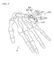
- Fig. 1 is a view showing an external fixator according to an embodiment of the present invention.
- Fig. 1 shows bones 10 of a human hand and shows that one bone 11 of the bones is broken at a portion 11c.
- the broken bone 11 includes a bone 11a and a bone 11b, and an external fixator 200 according to this embodiment is fixed to the bones in order to fix the bones while the bones are reset.
- pins 210 are inserted into the bones in order to reset the bone 11a and the bone 11b, respectively.
- the pins 210 are pierced to the skin and the pins 210 are inserted into the bones 11a and 11b.
- a ball joint 220 is connected to an end of each of the pins 210 opposite to the bone 11.
- the ball joint 220 includes a ball 221 used as a rotary member and a socket 222. While the ball 221 is fitted to the socket 222, the direction of the socket 222 can be changed with a high degree of freedom.
- the socket 222 has holes in which threadings are formed. A hexagon socket set screw is screwed into the hole, so that the socket 222 can be fixed to the ball 221.
- the coupling member 230 includes a first rod-like member 231, a second rod-like member 232, and a third rod-like member 233.
- the first rod-like member 231 is a substantially cylindrical member, and has a hole formed at the middle portion of an outer wall thereof and threadings formed on the inner walls of both ends thereof.
- Each of the second and third rod-like members 232 and 233 is a substantially cylindrical member, and a threading is formed at one end portion of each of the second and third rod-like members.
- One of the threadings formed at the both ends of the first rod-like member 231 corresponds to a right-hand thread, and the other thereof corresponds to a left-hand thread.
- the threading of the second rod-like member 232 corresponds to one of the threadings formed at the both ends of the first rod-like member, and the threading of the third rod-like member 233 corresponds to the other thereof.
- the rotational directions of the second and third rod-like members are opposite to each other. It is possible to increase or decrease a distance between the second and third rod-like members 232 and 233 by rotating the first rod-like member 231 while the second and third rod-like members 232 and 233 are inserted into the first rod-like member 231. For this reason, in this embodiment, it is possible to adjust the length of the coupling member 230 by rotating the first rod-like member 231.
- the ball joint 220 is connected to the end of each of the pins 210, and the coupling member 230 is connected to the socket 222. Further, since the length of the coupling member 230 can be adjusted, it is possible to easily adjust the position of a connection portion between the coupling member 230 and the ball joint 220 (a portion of the coupling member 230 fixed to the insertion portion of the socket 222 by a screw in this embodiment).
- the bones 11a and 11b exist in a living body and are broken, it is extremely difficult to fix the bones in the living body. Furthermore, since the bones 11a and 11b are pushed as the pins 210 are inserted into the bones, the positions or directions of the bones may be easily changed. Accordingly, it is extremely difficult to insert the pins 210 into the bones at desired positions or angles in the living body.
- the balls 221 are connected to the ends of the pins 210 exposed to the outside of the skin. Accordingly, it is very easy to fit the sockets 222 to the balls 221 at desired angles. Meanwhile, in this case, it is possible to separately and independently determine the direction of the socket 222 with respect to each of the pins 210, and to determine a relationship between the socket 222 and the coupling member 230 regardless of the insertion direction of the pin 210. Therefore, it is possible to provide a very high degree of freedom to the insertion direction of the pin 210 or the direction of the coupling member 230.
- the second and third rod-like members 232 and 233 can be inserted into the first rod-like member 231 by a screw mechanism. Furthermore, it is possible to adjust the length of the coupling member by rotating the first rod-like member 231. Therefore, regardless of the insertion direction of the pin 210, it is possible to very easily connect to the pin 210 to the ball joint 220 and to connect the ball joint 220 to the coupling member 230.
- the second rod-like member 232 and the socket 222 are temporarily fixed to each other and the third rod-like member 233 and the socket 222 are temporarily fixed to each other. Further, if the position of the connection portion is finely adjusted by adjusting the length of the coupling member 230 while one of the balls 221, which are connected to the ends of the pins 210 inserted into the bones at an arbitrary position and direction, is fitted to one socket 222, it is possible to very easily fit the other ball 221 to the other socket 222.
- the balls 221 are fitted to the sockets 222, respectively, the balls 221 and the sockets 222 are fixed to each other by screws, and the coupling member 230 is fixed to the sockets 222, so that it is possible to completely fix the external fixator 200.
- the fixing order of the other parts except for the pins 210 is not particularly limited in this embodiment.
- the various fixing orders may be employed.
- the sockets 222 are temporarily fixed to the balls 221 after the pins 210 are inserted into the bones, the second and third rod-like members 232 and 233 are inserted into the insertion portions of the sockets 222, and the first rod-like member 231 is disposed between the second and third rod-like members and connected thereto by means of a screw.
- an operation for releasing the temporary fixing or an operation for strengthening the temporary fixing by tightening screws may be appropriately employed.
- Fig. 2 is a view illustrating the structure of the pin 210 and the ball 221.
- the pin 210 is a substantially columnar member. One end portion of the pin becomes thinner toward the end thereof as shown in Fig. 2 , and has a threading 210a.
- the ball 221 is a substantially spherical body, and includes a hole 221a into which the pin 210 is inserted and screw holes 221b that are used to fix the pin 210 by screws. That is, the hole 221a is a hole passing through the center of the ball 221, and the inner diameter thereof is substantially the same as the outer diameter of the pin 210. Accordingly, it is possible to fit the pin 210 into the hole 221a.
- the pin 210 While being fitted into the hole 221a, the pin 210 is fixed by hexagon socket set screws 221c inserted into the screw holes 221b.
- the ball 221 has been connected to the end of the pin 210 in this embodiment.
- the pin 210 may be fixed by screws so that the pin 210 does not pass through the ball 221.
- one end of the pin may be cut and the ball 221 may by connected to one end of the pin 210.
- the ball 221 is connected to the end of the pin 210 and the pin 210 is not allowed to pass through the ball 221. Accordingly, the entire range where the pin 210 and the socket 222 do not interfere with each other may be referred to as an operation range of the socket 222. As a result, it is possible to provide a very high degree of freedom in the direction of the socket 222.
- Fig. 3A is a view where the surface of the socket 222 being in contact with the ball 221 is shown on the lower side and the insertion portion into which the coupling member 230 is inserted is shown on the upper side.
- Fig. 3B is a cross-sectional view taken along line A-A of Fig. 3A . Meanwhile, the inner structure of the socket will be shown by a dotted line in Fig. 3A .
- the socket 222 includes a body 222a that has a substantially semi-spherical shape, and a substantially columnar insertion portion 222b that protrudes from the body 222a.
- a substantially semi-spherical recess 222c is formed in the body 222a.
- the recess 222c is formed by cutting a semi-sphere that has substantially the same diameter as the ball 221. Accordingly, while the ball 221 is fitted to the socket 222, it is possible to adjust the direction of the socket 222 with a high degree of freedom.
- screw holes 222d are formed at four positions on the side surface of the body 222a.
- the screw holes 222d are holes that have the same diameter and are formed to reach the recess 222c formed in the body 222a from the outer wall of the body 222a.
- the screw holes 222d are positioned on a circumference circle of the body 222a at substantially regular intervals. Meanwhile, a plurality of screw holes 222d may be formed. The number of screw holes is not limited to four, and may be appropriately adjusted.
- a hexagon socket set screw 222e can be screwed into each of the screw hole 222d, and it is possible to fix the socket 222 to the ball 221 by screwing the hexagon socket set screws 222e into one or more screw holes 222d while the ball 221 is fitted to the socket 222. Meanwhile, in this embodiment, an intersection of lines passing through axes of the screw holes 222d corresponds to the centroid position of the ball 221 when the ball 221 is in contact with the recess 222c. Accordingly, the recess 222c of this embodiment is a recess in which a centroid of the ball may be disposed.
- the number of the screw holes 222d to be used to fix the socket may be determined according to the strength that is required to fix the socket. Further, since four screw holes 222d have been positioned on the circumference circle of the body 222a as described above in this embodiment, the socket 222 may be fixed to the ball 221 by using arbitrary screw holes 222d. Accordingly, it is possible to select screw holes 222d where the hexagon socket set screws 222e can be screwed without interfering with a portion of a human body regardless of the direction of the socket 222, thereby very easily screwing the hexagon socket set screws.
- the insertion portion 222b protrudes from the outer surface of the body 222a of the socket 222 in a direction opposite to the recess 222c, has a substantially columnar shape, and includes an insertion hole 222f that extends in a direction substantially orthogonal to an axis of the columnar shape.
- the inner diameter of the insertion hole 222f is substantially equal to the outer diameter of each of the second and third rod-like members 232 and 233, and the second or third rod-like member 232 or 233 can be inserted into the insertion hole 222f.
- a screw hole 222g which extends from the upper end of the insertion portion to the inside of the socket 222, is formed in the insertion portion 222b.
- a hexagon socket set screw 222h can be screwed into the screw hole. Accordingly, it is possible to fix the coupling member 230 to the socket 222 by screwing the hexagon socket set screw 222h into the screw hole 222g while the second or third rod-like member 232 or 233 is inserted into the insertion portion 222b.
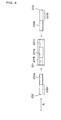
- FIG. 4 is a view illustrating the first, second, and third rod-like members 231, 232, and 233, which form the coupling member 230.
- the inner structure of the first rod-like member 231 will be shown by a dotted line.
- the first rod-like member 231 is a substantially cylindrical member.
- the first rod-like member has a hole 231a formed at the middle portion thereof and threadings 231b and 231c formed on the inner walls of portions that are closer to the both ends thereof than the hole 231a.
- the direction of the threading 231b is opposite to that of the threading 231c. For example, if the threading 231b corresponds to a right-hand thread, the threading 231c corresponds to a left-hand thread.
- each of the second and third rod-like members 232 and 233 is a substantially columnar member, and threadings 232a and 233a are formed on one end portions of the second and third rod-like members, respectively.
- the outer diameter of each of the second and third rod-like members 232 and 233 is substantially equal to the inner diameter of the first rod-like member 231.
- the direction of the threading 232a corresponds to the threading 231b
- the direction of the threading 233a corresponds to the threading 231c.
- the second rod-like member 232 may be screwed to the threading 231b, and the third rod-like member 233 may be screwed to the threading 231c.
- the direction of the threading 231b is opposite to that of the threading 231c as described above. Therefore, the rotational direction of the second rod-like member 232 when the second rod-like member is screwed to the first rod-like member 231 is opposite to that of the third rod-like member 233 when the third rod-like member is screwed to the first rod-like member 231.
- Columnar portions 232b and 233b which are formed at portions of the second and third rod-like members 232 and 233 opposite to the threadings 232a and 233a, are portions that can be inserted into the above-mentioned insertion portions 222f and fixed by the hexagon socket set screws 222h. Accordingly, when the second and third rod-like members 232 and 233 are fixed to the sockets 222, it is possible to adjust the length of the coupling member 230 while the second and third rod-like members 232 and 233 are inserted into the insertion portions 222f, and to fix the second and third rod-like members by bringing the hexagon socket set screws 222h into contact with arbitrary positions on the columnar portions 232b and 233b.
- the positions where the hexagon socket set screws 222h are in contact with the columnar portions 232b and 233b can be adjusted in a longitudinal direction of the coupling member 230 (L in Fig. 4 ). Accordingly, even though the pins 210 are inserted into the bone 11 in certain directions and a distance between the balls 221 connected to the pins 210 corresponds to a certain value, it is possible to adjust the length of the coupling member 230, to easily make the distance between the balls correspond to the length of the coupling member, and to very easily fix the external fixator 200.
- the length of the coupling member 230 can be adjusted in this embodiment, it is possible to connect the sockets 222 after adjusting the length of the coupling member 230 as short as possible. Therefore, it is possible to make the external fixator 200 as small as possible, and to suppress the influence on the action of a user of the external fixator 200.
- the columnar portions 232b and 233b have been formed at the second and third rod-like members 232 and 233 so as to be in contact with the hexagon socket set screws 222h.
- Fig. 5 is a view showing an external fixator 201 according to an embodiment where a coupling member is composed of a columnar member.
- a coupling member is employed instead of the above-mentioned coupling member 230 and the coupling member 235 is a columnar member. Accordingly, it is possible to provide the external fixator 201 by using very simple structure.
- connection portions of the coupling member 235 connected to the ball joints may be formed in a columnar shape.
- a portion of the coupling member between two connection portions may be formed in the shape of a prism or the combination of several plates.
- a coupling member 236 is composed of two rod-like members 236a and 236b and rotating mechanisms 236c to 236e.
- the rod-like member 236a is connected to an annular member 236c, and the rod-like member 236b is also connected to an annular member 236d. Further, a screw 236e may be inserted into holes of the annular members 236c and 236d, and the annular members 236c and 236d may be connected and fixed to each other by a nut (not shown). Accordingly, if the annular members 236c and 236d are aligned with each other and the screw 236e is inserted into the holes thereof, the rod-like members 236a and 236b can be rotated about the screw 236e on a common plane.
- each of the rod-like members 236a and 236b has a columnar shape. Accordingly, when the rod-like members 236a and 236b are connected to the sockets 222, it is possible to arbitrarily select the positions of the connection portions therebetween. Therefore, even though the pins 210 are inserted into the bone in any direction, it is possible to very easily fit the external fixator 202 by adjusting the rotation angles of the rod-like members 236a and 236b, adjusting connection positions where the rod-like members 236a and 236b are connected to the sockets 222, and directions when the balls 221 are fitted to the sockets 222.
- a method of fixing the annular members 236c and 236d is not limited to a method using the combination of the screw 236e and the nut. As long as the annular members 236c and 236d can be rotated with respect to each other, various structures may be employed. Further, the rod-like members 236a and 236b are rotated on the common plane in this embodiment, but may be formed to be rotated with a higher degree of freedom by using ball joints and the like.
- Fig. 7 is a view showing an external fixator where a socket of a ball joint is connected to a pin.
- the same structures as those of the above-mentioned embodiment are indicated by the same reference numerals. That is, the structure of a pin 210 and a ball joint 220 are the same as that of the pin and the ball joint of the above-mentioned embodiment, but a method of connecting the ball joint 220 to the pin 210 and the structure of a coupling member are different from those of the above-mentioned embodiment.
- the socket 222 of the ball joint 220 is connected to the pin 210.
- the pin 210 is inserted into an insertion portion 222f of the socket 222, and the socket 222 is fixed to the pin 210 by a hexagon socket set screw 222h. Adjustment, where the diameter of the insertion portion 222f is aligned with the diameter of the pin 210, may be appropriately performed.
- a coupling member of this embodiment includes a first rod-like member 237a, a second rod-like member 237b, and a third rod-like member 237c.
- the first rod-like member 237a is a substantially cylindrical member
- each of the second and third rod-like members 237b and 237c is a substantially columnar member.
- threadings having opposite directions are formed on the inner walls of both ends of the first rod-like member 237a, and threadings corresponding to the threadings of the first rod-like member are formed on one end portion of each of the second and third rod-like members 237b and 237c.
- the second and third rod-like members 237b and 237c are screwed to the first rod-like member 237a, it is possible to form a coupling member 237 of which the length can be adjusted by the rotation of the first rod-like member 237a. End portions of the second and third rod-like members 237b and 237c opposite to the threadings can be inserted into holes of balls 211, and the second and third rod-like members 237b and 237c can be fixed to the balls 221 by hexagon socket set screws 221c.
- each of the holes 221a or the diameter of each of the second and third rod-like members 237b and 237c may be appropriately determined even in this case.
- portions where the balls 221 and the second and third rod-like members 237b and 237b are connected to each other correspond to connection portions. Since it is possible to adjust the length of the coupling member 237 by rotating the first rod-like member 237a as described above, it is possible to also change the positions of the connection portions in a longitudinal direction of the coupling member 237 in this embodiment.
- the socket 222 When the socket 222 is connected to the pin 210 in the above-mentioned structure, the socket 222 can be freely rotated about the pin 210. Further, while the balls 221 are fixed to the second and third rod-like members 237b and 237c, it is possible to adjust the length of the coupling member 237. Accordingly, even though the pins 210 are inserted into the bone in any manner, it is possible to completely fix the external fixator 203 by adjusting the directions of the sockets 222 and the length of the coupling member 237.
- one pin 210 is inserted into each of the separated bones 11a and 11b in the above-mentioned embodiment.
- a plurality of pins 210 may be inserted into a bone, and two arbitrary pairs thereof may be connected by ball joints or coupling members.
- one pin 210 may be inserted into a plurality of bones.
- the pin 210 may pass through the bone 11a, and the pin 210 passing through the bone 11a may be further inserted into the bone 11b in order to reset the bones. That is, a method of inserting the pins 210 may be appropriately changed according to the state of the broken bone, the size of the bone, the strength required to reset bones, etc.
- each of the members has been fixed using hexagon socket set screws in the above-mentioned embodiment.
- each of the members may be fixed using slotted set screws and may be fixed using various means other than screws.
- the connection between the ball 221 and the pin 210 or the connection between the ball 221 and the socket 222 may be performed by fitting.
- the substantially semi-spherical body 222a having the substantially semi-spherical recess 222c has been exemplified in the above-mentioned embodiment.
- the recess may have any shape without being limited to the semi-spherical shape.
- the shape of the body 222a is not limited to the semi-spherical shape, and the body may employ various structures such as a rectangular shape.
- the above-mentioned ball joint 220 (hereinafter, referred to as an end joint), which includes the ball 221 and the socket 222, is connected to the end of a pin 210.
- Another ball joint (hereinafter, referred to as an intermediate joint) is provided between the end joint and a threading 210a of the pin 210.
- Fig. 8 is a view showing a rotary member 2210 that connects the intermediate joint to the pin 210.
- the rotary member 2210 has the structure where a ball 2211 and a cylindrical insertion portion 2212 are connected to each other as shown in Fig. 8 . Since the ball 2211 can be fitted to the above-mentioned socket 222, it is possible to rotate the socket 222 around the outer periphery of the ball 2211 while the socket 222 and the ball 2211 are in contact with each other, and to fix the socket to the ball by screws.
- the insertion portion 2212 includes a hole 2210a that extends in a direction orthogonal to an axis of the insertion portion and passes through the insertion portion 2212, and a screw hole 2210b that is formed parallel to the axis of the insertion portion.
- the hole 2210a is a hole into which the pin 210 is inserted
- the screw hole 2210b is a screw hole to which the pin 210 inserted into the hole 2210a is fixed by screws.
- the inner diameter of the hole 2210a is substantially equal to the outer diameter of the pin 210. Accordingly, it is possible to fit the pin 210 into the hole 2210a. Further, while being fitted into the hole 2210a, the pin 210 is fixed by a hexagon socket set screw 2210c inserted into the screw hole 2210b.
- Fig. 9 is a schematic view showing a usage example of the external fixator according to this embodiment.
- Fig. 9 shows that three pins 210 are inserted into bones 11c and 11d. In this case, two pins 210 are inserted into the bone 11c, one pin 210 is inserted into the bone 11d, and an end joint (ball joint 220) and an intermediate joint (ball joint 2200) are connected to each of the pins.
- the end joint includes a ball 221 and a socket 222 like the ball joint shown in Fig. 1 , and is connected to the end of each of the pins.
- the intermediate joint including a rotary member 2210 and a socket 222 is connected to the pin 210.
- the rotary member 2210 is connected to each of the pins 210 and the rotary members 2210 are temporarily fixed between the ends of the pins 210 and the bones 11c and 11d by the hexagon socket set screws 2210c. Further, while the rotary members 2210 are fitted to the sockets 222, respectively, the rotary members 2210 and the sockets 222 are temporarily fixed to each other.
- each of the coupling members 235a and 235b is the same as the coupling member 235 shown in Fig. 5
- the coupling member 238 is a member that is formed by bending the coupling member 235.
- the sockets 222 and the coupling members 235a, 235b, and 238 are fixed to each other by screws.
- the directions of the coupling members of the ball joints connected to the pins 210 are not limited to one direction, and the coupling members may be connected to the pins while the directions of the coupling members are set to several directions. Accordingly, it is possible to fix the pins 210 by the coupling members that extend in several directions, to freely set the directions of the coupling members, and to maintain the external fixator while the external fixator is firmly fixed.
- the external fixator can remain firmly fixed due to the presence of the coupling member 235a.
- the external fixator can remain firmly fixed due to the presence of the coupling members 235b and 238.
- the structure shown in Fig. 9 is merely illustrative.
- the structure of the coupling member is not limited to the structure that includes the coupling members 235a, 235b, and 238, and may employ the above-mentioned various coupling members.
- the size of each of the ball joints 220 and 2200 may be appropriately determined according to the size of a bone to be reset, and may vary by the position of the pin 210.
- each of the screws is not limited to a hexagon socket set screw, and various screws may be employed as the screws.
- the structure of the socket 222 of this embodiment is the same as the structure shown in Fig. 3 , screw holes are formed on the periphery of the socket 222 at regular intervals (at four positions in this embodiment), and axes of the screw holes intersect at the center of the recess 222c. Accordingly, hexagon socket set screws 222e can be screwed to the socket 222 in several directions. As a result, it is very easy to fix the external fixator.
- the coupling member 235a is formed near a screw hole 222d indicated by an arrow Ar in the embodiment shown Fig. 9 , it is difficult to screw the hexagon socket set screw 222e to the screw hole 222d.
- two linear coupling members 235a and 235b and one bent coupling member 238 are used in the embodiment shown in Fig. 9 .
- the shapes of the coupling members are not limited thereto.
- a coupling member of which a portion except for both ends is curved may be employed. If this coupling member is employed, pins can be inserted into a substantially columnar bone, such as a finger or an arm, in substantially opposite directions, and ball joints connected to the pins can be connected to each other by the coupling member.
- the structure where a plurality of ball joints are connected to one pin as described above may be achieved by structure other than the structure shown in Figs. 8 and 9 .
- a member, which is connected to the pin of the above-mentioned intermediate joint may be formed of the socket 222 as shown in Fig. 7 .
- the ball joint 320 fixes a pin 210 with a coupling member 235 and is connected to another ball joint 320 (not shown) by the coupling member 235.
- the ball joint 320 is substituted with the above-mentioned ball joint, so that various external fixators may be formed. That is, as for the structure of the external fixator except for the ball joint, the structure of the above-mentioned embodiment may be applied to the ball joint 320.
- a rotary member 321 is a ball having a hole 321a into which the pin 210 is inserted, and a screw hole 321b to which the pin 210 is fixed by a screw. While being inserted into the hole 321a, the pin 210 is fixed by the set screw 321c screwed to the screw hole 321b.
- a first thread 322b which forms a male thread, is formed at a supporting member 322.
- a first supporting portion 322a by which the rotary member 321 is rotatably supported, is formed at the end portion of the first thread 322b.
- the first supporting portion 322a is a recessed surface that has a curvature radius substantially equal to the radius of the rotary member 321. It is preferable that the first supporting portion 322a has a shape to be supported at three points together with the rotary member 321. Further, it is preferable that the centroid of the three points pass through an axis of rotation of the first thread 322b and a plane including the three points be perpendicular to the axis of rotation of the first thread 322b.
- centroid of four or more contact points correspond to the center of the rotary member 321. If the supporting portion 322a is a recessed surface that has a curvature radius substantially equal to the radius of the rotary member 321, a centroid of contact points corresponds to the center of the rotary member 321.
- the coupling member 235 is inserted into the through hole 322c, and is fixed to the supporting member 322 by a screw (not shown) that is screwed to the screw hole 322d.
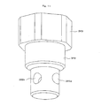
- a fastening member 323 has a tubular shape, has openings at both end portions thereof, and receives the rotary member 321. That is, the fastening member 323 has a tubular shape where the diameter R1 (see Fig. 12A ) of one opening is larger than the diameter of the rotary member 321. Further, the fastening member 323 is a specific nut, and the outer surface of the fastening member has the shape of side surfaces of a substantially hexagonal column that can be held by a spanner.
- a second thread 323a which forms a female thread corresponding to the first thread 322b, is formed at one end portion of the fastening member 323.
- the smaller diameter of the second thread 323a is designed to be larger than the diameter of the rotary member 321. Accordingly, the fastening member 323 can receive the rotary member 321. Meanwhile, the relationship between the female and male threads of the fastening member 323 and the supporting member 322 may be reversed. That is, a male thread is formed on the outer surface of the fastening member 323, and a female thread may be formed on the inner surface of the supporting member 322.
- a second supporting portion 323b which can support the rotary member 321 at at least three points, is formed at the other end portion of the fastening member 323.
- the second supporting portion 323b is a portion that protrudes toward a central axis of the fastening member 323.
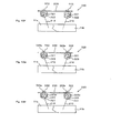
- the inner end of the second supporting portion 323b has a circular shape as shown in Fig. 12A . Since an inner diameter R2 of the second supporting portion 323b is designed to be smaller than the diameter of the rotary member 321, the second supporting member 323b can support the rotary member 321 at at least three points.
- An end face of the second supporting portion 323b close to the second thread 323a (upper side of a plane of Fig. 10 ) has a tapered shape and the diameter of the end face is increased toward the open end of the fastening member 323 close to the second thread 323a.
- the second supporting portion 323b can press the rotary member 321 against the first supporting portion 322a
- the second supporting portion may have any shape.
- the second supporting portion may have a shape that has a plurality of convex portions as shown in Fig. 12B . It is preferable that a centroid of contact points between the rotary member 321 and the first and second supporting portions 322a and 323b always correspond to the center of the rotary member 321 when the second thread 323a is screwed to the first thread 322b while the rotary member 321 is in contact with the first and second supporting portions 322a and 323b.
- the second supporting portion 323b have a shape to support the rotary member 321 at least three points of which a centroid is positioned on the central axis of the second thread 323a on a plane perpendicular to the central axis of the second thread 323a.
- forces required for adjusting an attitude of the coupling member 235 with respect to the pin 210 can be fixed while being simultaneously adjusted for the attitude change in all directions.
- forces for fixing the attitude of the coupling member 235 with respect to the pin 210 can be simultaneously increased for the attitude change in all directions. As a result, it is easier to fix bones by the external fixator.
- the rotary member 321 can be pressed against the first supporting portion 322a at one point of the second supporting portion 323b.
- the sufficient condition in this case is that a straight line, which passes through the contact point between the second supporting portion 323b and the rotary member 321 and is parallel to the central axis of the second thread 323a, may pass through the inside of a polygon whose apexes are the contact points between the first supporting portion 322a and the rotary member 321 and the central axis of the second thread 323a may pass through the inside of the polygon.
- An end face of the second supporting portion 323b distant from the second thread 323a (lower side of a plane of Fig. 10 ) has a tapered shape and the diameter of the end face is increased toward the open end of the fastening member 323 where the second supporting portion 323b is formed. If the end face of the second supporting portion 323b is designed to have such a tapered shape, the operation range of the pin 210 broadens.
- the ends of the pins 210 are inserted into broken bones 11a and 11b by using a drill and then fixed to the bones, respectively ( Fig. 13A ).
- each of the pins 210 is cut to a desired length ( Fig. 13B ).
- the fastening member 323 is fitted to each of the pins 210 in an appropriate direction, and the rotary member 321 is fixed to the end of each of the pins 210 by using the set screw 321b ( Fig. 13C ).
- the coupling member 235 is inserted into the through hole 322c of each of the supporting members 322 ( Fig. 13E ). Since the ball joint 320 can freely move and the position of the connection portion between the coupling member 235 and the ball joint 320 can be freely adjusted at this time, it is easy to insert the coupling member 235 into the through hole 322c of the supporting member 322. When the ball joint 320 is allowed to freely move and the coupling member 235 is only inserted into the through hole 322c without being fixed, it is possible to freely adjust the bonding state of the broken bones 11a and 11b.
- the fastening member 323 is fastened to the supporting member 322 by using a wrench or the like ( Fig. 13F ). That is, the second thread of the fastening member 323 is fastened to the first thread of the supporting member 322.
- the fastening member 323 is much larger than, for example, the set screw 222e shown in Fig. 3 , it is easy to rotate the fastening member 323 by the wrench.
- each of the rotary members 321 is in contact with the fastening member 323 and the supporting member 322, it is possible to uniformly adjust forces, which are required for adjusting an attitude of the coupling member 235 with respect to the pin 210, in all directions by adjusting the amount of fastening of the fastening member 323.
- the clearance between the coupling member 323 and the through hole 322c is negligibly small, it is possible to uniformly adjust forces, which are required for adjusting the bonding state of the broken bones 11a and 11b, in all directions.
- the coupling member 235 cannot be rotated. Accordingly, it is possible to adjust the amount of fastening of the fastening member 323 of the other ball joint 320 with one hand. That is, the coupling member 235 does not need to be held in this state. Therefore, while adjusting the amount of fastening of the fastening member 323 with one hand, it is possible to handle an affected part.
- the coupling member 323 and the through hole 322c are negligibly small, the attitude and position of one bone of the broken bones 11a and 11b is not substantially changed with respect to those of the other bone while the fastening members 323 of the two ball joints 320, which are connected to each other by the coupling member 235, are excessively fastened. Accordingly, while confirming the bonding state of the broken bones 11a and 11b by using an X-ray image, a person in charge can fix the broken bones 11a and 11b in an appropriate bonding state all by himself. After that, when the broken bones 11a and 11b are appropriately bonded, the coupling member 235 is fixed to each of the supporting members 322 by using a set screw 322e ( Fig. 13G ). Therefore, it is possible to completely fix the reset state of the broken bones 11a and 11b.
- a third screw 323d be screwed to a screw hole formed at the fastening member 323 so that the end of the third screw 323d presses the supporting member 322.
- the thread of the first thread 322b of the supporting member 322 be pressed and stripped. Therefore, it is possible to reliably prevent the fastening member 323 from being loosen.
- the ball joint does not move. If a person in charge of the treatment handles an affected part and the ball joint can be fixed while being allowed to move, it is easier to handle the external fixator. However, it is not easy to achieve this state by adjusting the amount of fastening of the screw. Accordingly, it is preferable that the member (socket and supporting member) to which the coupling member is fixed and the member (rotary member) to which the pin is fixed attract each other by a magnetic force while being rotatable with respect to each other. In this structure, for example, the socket 222 and the ball 211 shown in Fig.
- the supporting member 322 and the rotary member 321 shown in Fig. 10 are formed of plastic magnets that are magnetized so as to attract each other.
- Materials such as ferrite, neodymium, an iron oxide, a chrome oxide, and cobalt, which are used to obtain a magnetic force required on a basis of size and mass of the external fixator, may be employed as the ferromagnetic body.
- an alloy be employed as the ferromagnetic body in order to obtain both strength and a magnetic force.
- components of the external fixator be made of a material having X-ray transmittance higher than that of a bone.
- the coupling member is made of composite plastics that may be reinforced with carbon fiber, glass fiber, or the like and the ball joint is be composed of a plastic magnet. If the above-mentioned various plastics are used, it is possible to reduce the weight of the external fixator and to reduce manufacturing costs of components because injection molding can be applied. It is also possible to prevent rust.
- Base materials of composite plastics may be thermoplastic resins or thermosetting resins.
- engineering plastics such as polycarbonate, and super engineering plastics such as polyphenylene sulfide, amorphous polyarate, an aromatic polyetherketone resin, and thermoplastic polyimide may be used.
- a plastic magnet is used for the ball joint, so that it is possible to obtain an external fixator that allows the pin and the coupling member to be temporarily fixed by a magnetic force and allows the broken bones to be easily confirmed.
- the socket 222 and the ball 211 shown in Fig. 2 are formed of plastic magnets that are magnetized so as to attract each other or the supporting member 322 and the rotary member 321 shown in Fig. 10 are formed of plastic magnets that are magnetized so as to attract each other, so that it is possible to obtain an external fixator that allows a ball joint to be temporarily fixed by a magnetic force and allows the broken bones to be easily confirmed.
- the present invention may be used for a treatment of broken bones. Further, the present invention may be provided as a product by a manufacturer of therapeutic devices for broken bones.
Landscapes
- Health & Medical Sciences (AREA)
- Orthopedic Medicine & Surgery (AREA)
- Surgery (AREA)
- Life Sciences & Earth Sciences (AREA)
- Heart & Thoracic Surgery (AREA)
- Nuclear Medicine, Radiotherapy & Molecular Imaging (AREA)
- Engineering & Computer Science (AREA)
- Biomedical Technology (AREA)
- Medical Informatics (AREA)
- Molecular Biology (AREA)
- Animal Behavior & Ethology (AREA)
- General Health & Medical Sciences (AREA)
- Public Health (AREA)
- Veterinary Medicine (AREA)
- Neurology (AREA)
- Surgical Instruments (AREA)
Claims (12)
- Externer Fixateur, umfassend:mehrere Stifte (210), die in Knochen eingeführt werden,ein Kopplungselement (235) undmehrere Kugelgelenke (320), die das Kopplungselement an den Stiften befestigen und die über das Kopplungselement miteinander verbunden sind, wobei die mehreren Kugelgelenke jeweils umfassen:ein Drehelement, das eine Kugel (321) ist,ein Stützelement (322), an dem ein erstes Gewinde (322b) und ein erster Stützabschnitt (322a), der die Kugel drehbar lagert, ausgebildet sind, undein Befestigungselement (323), das eine Röhrenform aufweist, das an beiden Endabschnitten davon Öffnungen aufweist und das die Kugel aufnimmt, wobei an einem Endabschnitt des Befestigungselementes ein zweites Gewinde (323a) ausgebildet ist, das dem ersten Gewinde (322b) entspricht, und an dem anderen Endabschnitt ein zweiter Stützabschnitt (323b) ausgebildet ist, der die Kugel durch Einschrauben des zweiten Gewindes in das erste Gewinde gegen den ersten Stützabschnitt (322a) drückt,wobei ein Stift (210) an dem Drehelement befestigt ist, während er in eine an dem Drehelement ausgebildete Öffnung (321 a) eingeführt wird, unddas Kopplungselement an dem Stützelement befestigt ist,
dadurch gekennzeichnet, dassdas Drehelement (321) und das Stützelement (322) aus einem Kunststoffmagneten ausgebildet sind. - Externer Fixateur nach Anspruch 1,
wobei die Öffnung (321 a) an einem einzelnen Element ausgebildet ist, das das gesamte Drehelement (321) bildet. - Externer Fixateur nach Anspruch 1 oder 2,
wobei das Drehelement (321) klein genug ist, um durch eine Öffnung des Befestigungselementes (323) hindurchzugehen, bis es mit dem zweiten Stützabschnitt (323b) in Kontakt kommt. - Externer Fixateur nach einem der Ansprüche 1 bis 3,
wobei die an dem Drehelement ausgebildete Öffnung (321 a) durch das Drehelement (321) hindurchreicht. - Externer Fixateur nach einem der Ansprüche 1 bis 4,
wobei der in die Öffnung (321 a) eingeführte Stift mittels einer Schraube an dem Drehelement (321) befestigt ist, die mit einer Schrauböffnung (321 b) verschraubt ist, die zu der an dem Drehelement ausgebildeten Öffnung führt. - Externer Fixateur nach einem der Ansprüche 1 bis 5,
wobei, wenn das zweite Gewinde (323a) mit dem ersten Gewinde (323b) verschraubt ist, der zweite Stützabschnitt (323b) die Kugel (321) gegen den ersten Stützabschnitt (322a) drückt, während er die Kugel an drei Punkten stützt, und
wenn die Kugel (321) mit den ersten und zweiten Stützabschnitten (322a, 323b) in Kontakt ist, ein Schwerpunkt der Kontaktpunkte zwischen der Kugel und den ersten und zweiten Stützabschnitten immer der Mitte der Kugel entspricht. - Externer Fixateur nach einem der Ansprüche 1 bis 6, ferner umfassend:ein drittes Gewinde (323d), das mit einem verschraubt ist, das außerhalb des Befestigungselementes (323) und des Stützelementes (322) vorgesehen ist, um dadurch das andere, das innerhalb vorgesehen ist, zu drücken, und das das Befestigungselement (323) an dem Stützelement (322) befestigt, so dass das Befestigungselement und das Stützelement nicht gedreht werden.
- Externer Fixateur nach einem der Ansprüche 1 bis 7,
wobei wenigstens eines von dem Drehelement (321) und dem Stützelement (322) magnetisiert ist, so dass es das andere davon anzieht. - Externer Fixateur nach einem der Ansprüche 1 bis 8,
wobei die mehreren Kugelgelenke (320) an jedem der Stifte (210) befestigt sind. - Externer Fixateur nach einem der Ansprüche 1 bis 9,
wobei das Kopplungselement (235) mehrere Verbindungsabschnitte umfasst, die die Kugelgelenke (320) verbinden, und
die Positionen der mehreren Verbindungsabschnitte wenigstens in einer Längsrichtung des Kopplungselementes (235) eingestellt werden. - Externer Fixateur nach einem der Ansprüche 1 bis 10,
wobei das Kopplungselement (235) ein erstes stabartiges Element und zweite und dritte stabartige Elemente umfasst, die mit beiden Enden des ersten stabartigen Elementes mittels eines Schraubmechanismus verbunden sind, und
einer der Schraubmechanismen, die an den beiden Enden vorgesehen sind, ein rechtsgängiges Gewinde ist und das andere davon ein linksgängiges Gewinde ist. - Externer Fixateur nach einem der Ansprüche 1 bis 11,
wobei das Kopplungselement (235) zwei stabartige Elemente umfasst und die beiden stabartigen Elemente so miteinander verbunden sind, dass sie in wenigstens einer Ebene zwischen zwei Kugelgelenken (320) rotieren, die mittels des Kopplungselementes (235) miteinander verbunden sind.
Applications Claiming Priority (3)
| Application Number | Priority Date | Filing Date | Title |
|---|---|---|---|
| PCT/JP2006/310561 WO2007138659A1 (ja) | 2006-05-26 | 2006-05-26 | 創外固定器 |
| PCT/JP2006/320293 WO2007138722A1 (ja) | 2006-05-26 | 2006-10-11 | 創外固定器 |
| PCT/JP2007/060728 WO2007139031A1 (ja) | 2006-05-26 | 2007-05-25 | 創外固定器 |
Publications (3)
| Publication Number | Publication Date |
|---|---|
| EP2030583A1 EP2030583A1 (de) | 2009-03-04 |
| EP2030583A4 EP2030583A4 (de) | 2012-01-04 |
| EP2030583B1 true EP2030583B1 (de) | 2015-08-26 |
Family
ID=38778188
Family Applications (1)
| Application Number | Title | Priority Date | Filing Date |
|---|---|---|---|
| EP07744162.4A Not-in-force EP2030583B1 (de) | 2006-05-26 | 2007-05-25 | Externer fixator |
Country Status (6)
| Country | Link |
|---|---|
| US (1) | US8366710B2 (de) |
| EP (1) | EP2030583B1 (de) |
| JP (1) | JP4304321B2 (de) |
| KR (1) | KR101377734B1 (de) |
| CN (1) | CN101453959B (de) |
| WO (3) | WO2007138659A1 (de) |
Families Citing this family (41)
| Publication number | Priority date | Publication date | Assignee | Title |
|---|---|---|---|---|
| GB2444907A (en) * | 2006-12-20 | 2008-06-25 | Promedics Ltd | A joint fixator |
| JP5571001B2 (ja) | 2008-02-05 | 2014-08-13 | テキサス スコティッシュ ライト ホスピタル フォー チルドレン | 創外固定器リング |
| US8439914B2 (en) * | 2008-02-08 | 2013-05-14 | Texas Scottish Rite Hospital For Children | External fixation strut |
| WO2009102904A1 (en) | 2008-02-12 | 2009-08-20 | Texas Scottish Rite Hospital For Children | Fast adjust external fixation connection rod |
| EP2252222B1 (de) * | 2008-02-18 | 2014-03-26 | Texas Scottish Rite Hospital For Children | Werkzeug zur einstellung einer externen fixierstrebe |
| US8282636B2 (en) | 2009-08-10 | 2012-10-09 | Imds Corporation | Orthopedic external fixator and method of use |
| US9066757B2 (en) * | 2009-08-10 | 2015-06-30 | Virak Orthopedic Research Llc | Orthopedic external fixator and method of use |
| ES2668075T3 (es) * | 2009-09-11 | 2018-05-16 | Stryker European Holdings I, Llc | Componente de fijación externa |
| US8858555B2 (en) | 2009-10-05 | 2014-10-14 | Stryker Trauma Sa | Dynamic external fixator and methods for use |
| US8945128B2 (en) | 2010-08-11 | 2015-02-03 | Stryker Trauma Sa | External fixator system |
| EP2417923B1 (de) | 2010-08-11 | 2013-11-13 | Stryker Trauma SA | Externes Befestigungssystem |
| US11141196B2 (en) | 2010-08-11 | 2021-10-12 | Stryker European Operations Holdings Llc | External fixator system |
| CA2809002C (en) | 2010-08-20 | 2017-11-21 | Amei Technologies, Inc. | Method and system for roentgenography-based modeling |
| EP2438869B1 (de) | 2010-10-07 | 2015-04-29 | Stryker Trauma SA | Kupplungselement für einen externen Fixierer |
| US8721566B2 (en) * | 2010-11-12 | 2014-05-13 | Robert A. Connor | Spinal motion measurement device |
| US9247997B2 (en) * | 2011-09-30 | 2016-02-02 | Ethicon Endo-Surgery, Inc. | Patient-referenced surgical support frame |
| US9101398B2 (en) | 2012-08-23 | 2015-08-11 | Stryker Trauma Sa | Bone transport external fixation frame |
| US8826754B2 (en) * | 2012-08-24 | 2014-09-09 | Tektronix, Inc. | Modular probe assembly having force protection and articulation |
| US9101413B2 (en) * | 2012-10-16 | 2015-08-11 | DePuy Synthes Products, Inc. | Pop on spreader system |
| US8574232B1 (en) | 2012-11-13 | 2013-11-05 | Texas Scottish Hospital for Children | External fixation connection rod for rapid and gradual adjustment |
| US9155561B2 (en) | 2013-03-06 | 2015-10-13 | Stryker Trauma Sa | Mini-rail external fixator |
| EP2967674B1 (de) | 2013-03-15 | 2024-02-21 | Biomet C.V. | Polyaxiales gehäuse für einen fixateuer externe |
| US9962188B2 (en) | 2013-10-29 | 2018-05-08 | Cardinal Health 247. Inc. | External fixation system and methods of use |
| CN106102616B (zh) * | 2014-01-24 | 2018-10-16 | 奥瑟菲克斯有限公司 | 用于外固定装置的长形销 |
| US10314618B2 (en) * | 2014-07-25 | 2019-06-11 | The General Hospital Corporation | System and method for an external hip fixator |
| WO2016080921A1 (en) * | 2014-11-20 | 2016-05-26 | Karadeni̇z Emre | Magnetic apparatus for wire retainers |
| US10531896B2 (en) | 2015-08-10 | 2020-01-14 | Stryker European Holdings I, Llc | Distraction tube with wire clamp |
| JP6206853B2 (ja) * | 2015-11-02 | 2017-10-04 | 学校法人静岡理工科大学 | 創外固定器 |
| CN105250017B (zh) * | 2015-11-30 | 2018-03-06 | 昆明医科大学第二附属医院 | 一种能够多向提供角度补偿的矫形棒连接器 |
| US9936976B2 (en) * | 2016-03-01 | 2018-04-10 | Pbd, Patent & Business Development Ag | Bracket for external fixation of bones |
| US10342580B2 (en) | 2016-03-01 | 2019-07-09 | Pbd, Patent & Business Development Ag | Bracket for external fixation of bones |
| US10010350B2 (en) | 2016-06-14 | 2018-07-03 | Stryker European Holdings I, Llc | Gear mechanisms for fixation frame struts |
| US10874433B2 (en) | 2017-01-30 | 2020-12-29 | Stryker European Holdings I, Llc | Strut attachments for external fixation frame |
| CN107080580A (zh) * | 2017-04-28 | 2017-08-22 | 徐永清 | 一种组合式髋关节外固定活动架 |
| JP7142820B2 (ja) * | 2018-02-07 | 2022-09-28 | 公立大学法人大阪 | 手指用のガイド一体型創外固定器および手指用のガイド一体型創外固定器の製造方法 |
| CN112770685B (zh) * | 2018-09-28 | 2024-11-05 | Pmu创新股份有限公司 | 医疗定位装置 |
| US12274475B2 (en) * | 2018-10-04 | 2025-04-15 | Peter M. Stevens | Automated coupled torsional fixators and method of use |
| WO2020072392A1 (en) * | 2018-10-04 | 2020-04-09 | Peter Stevens | Coupled torsional fixator and method of use |
| US11141197B2 (en) * | 2019-06-24 | 2021-10-12 | DePuy Synthes Products, Inc. | Polyaxial strut for external fixation |
| CN110811798B (zh) * | 2019-11-27 | 2022-06-07 | 张浩然 | 一种用于四肢骨折的外固定器 |
| US12433641B2 (en) | 2023-09-20 | 2025-10-07 | Şehmuz Işin | Unilateral external fixator apparatus and control method |
Citations (1)
| Publication number | Priority date | Publication date | Assignee | Title |
|---|---|---|---|---|
| JPH11182529A (ja) * | 1997-12-16 | 1999-07-06 | Maguna:Kk | ボールジョイント |
Family Cites Families (38)
| Publication number | Priority date | Publication date | Assignee | Title |
|---|---|---|---|---|
| US2346346A (en) * | 1941-01-21 | 1944-04-11 | Anderson Roger | Fracture immobilization splint |
| CA1077363A (en) * | 1976-08-09 | 1980-05-13 | Richard F. Kronner | Fracture reducing and joint immobilizing apparatus |
| US4502473A (en) * | 1981-08-06 | 1985-03-05 | National Research Development Corp. | Apparatus for external fixation of bone fractures |
| US4554915A (en) * | 1983-03-08 | 1985-11-26 | Richards Medical Company | Bone fixation frame |
| GB8409564D0 (en) * | 1984-04-12 | 1984-05-23 | Evans M | Orthopaedic fracture fixation apparatus |
| US4895141A (en) * | 1984-04-26 | 1990-01-23 | Harrington Arthritis Research Center | Unilateral external fixation device |
| IT1181490B (it) | 1984-12-18 | 1987-09-30 | Orthofix Srl | Apparecchio ortopedico per la fissazione esterna assiale,ad ampia gamma di adattabilita' |
| US4620533A (en) * | 1985-09-16 | 1986-11-04 | Pfizer Hospital Products Group Inc. | External bone fixation apparatus |
| WO1989011254A1 (fr) * | 1988-05-26 | 1989-11-30 | Vsesojuzny Kurgansky Nauchny Tsentr ''vosstanovite | Appareil de compression-traction pour osteosynthese |
| EP0314021A3 (de) | 1987-10-26 | 1989-12-06 | Howmedica GmbH | Vorrichtung zum Fixieren von Knochenteilen |
| DE8901908U1 (de) | 1989-02-15 | 1989-03-30 | Mecron Medizinische Produkte Gmbh, 1000 Berlin | Orthopädische Fixiereinrichtung |
| JPH0436828A (ja) | 1990-06-01 | 1992-02-06 | Hitachi Ltd | 情報処理装置とその表示装置 |
| WO1994000066A1 (de) | 1992-06-25 | 1994-01-06 | Synthes Ag Chur | Osteosynthetische fixationsvorrichtung |
| DE4231443C1 (de) | 1992-09-19 | 1993-10-14 | Pennig Dietmar | Osteosynthesehilfsmittel |
| US5443464A (en) * | 1993-02-16 | 1995-08-22 | Memphis Orthopaedic Design, Inc. | External fixator apparatus |
| IT1289103B1 (it) | 1996-05-15 | 1998-09-25 | Orthofix Srl | Fissatore esterno compatto |
| CN2334354Y (zh) * | 1998-01-14 | 1999-08-25 | 中国航天工业总公司七一一医院 | 手外科微型外固定器 |
| US6083228A (en) | 1998-06-09 | 2000-07-04 | Michelson; Gary K. | Device and method for preparing a space between adjacent vertebrae to receive an insert |
| JP3593262B2 (ja) * | 1998-06-10 | 2004-11-24 | 尚義 菅 | 脊椎固定具 |
| WO2000040163A1 (en) | 1998-12-31 | 2000-07-13 | Orthofix S.R.L. | Improved device for the external fixation of bones fractures, in particular ankle fractures |
| US6423062B2 (en) * | 2000-02-18 | 2002-07-23 | Albert Enayati | Bioabsorbable pin for external bone fixation |
| FR2808181B1 (fr) | 2000-04-28 | 2002-06-14 | Fixano | Fixateur externe pour l'immobilisation de fragments d'os, notamment au niveau du poignet |
| GB0107708D0 (en) * | 2001-03-28 | 2001-05-16 | Imp College Innovations Ltd | Bone fixated,articulated joint load control device |
| US6623638B2 (en) | 2001-06-01 | 2003-09-23 | Baxter International Inc. | Hemodialyzer having improved dialysate perfusion |
| JP3740640B2 (ja) | 2002-04-15 | 2006-02-01 | 廣章 野々宮 | 創外固定器 |
| DE10246177A1 (de) | 2002-10-02 | 2004-04-22 | Biedermann Motech Gmbh | Verankerungselement |
| FR2849766B1 (fr) * | 2003-01-15 | 2005-03-18 | Christian Dongar | Dispositif de blocage d'une broche d'osteosynthese dans une piece osseuse |
| JP4190331B2 (ja) | 2003-03-28 | 2008-12-03 | 株式会社エム・イー・システム | 創外固定器 |
| JP2004350774A (ja) | 2003-05-27 | 2004-12-16 | Oomikku:Kk | 創外固定器、及び刺しピン着脱継手 |
| JP2005065748A (ja) | 2003-08-27 | 2005-03-17 | Kozo Nakamura | クランプ具、および創外固定器 |
| JP4110208B2 (ja) * | 2003-08-28 | 2008-07-02 | 耕三 中村 | 創外固定器 |
| US7862586B2 (en) | 2003-11-25 | 2011-01-04 | Life Spine, Inc. | Spinal stabilization systems |
| EP1740112A1 (de) | 2004-04-16 | 2007-01-10 | Kyphon Inc. | Schraubenanordnung |
| US7186255B2 (en) | 2004-08-12 | 2007-03-06 | Atlas Spine, Inc. | Polyaxial screw |
| US8262656B2 (en) * | 2004-09-03 | 2012-09-11 | A.M. Surgical, Inc. | External fixation device for fractures |
| SE530162C2 (sv) | 2004-10-07 | 2008-03-11 | Dan Lundgren Ab | Förfarande och anordning för att framställa en protesstruktur på en patientmodell |
| ITPD20050266A1 (it) * | 2005-09-15 | 2007-03-16 | Mikai Spa | Apparato per il trattamento di patologie di origine malformativa e traumatica afferenti l'area del ginocchio |
| US7717916B2 (en) * | 2007-08-16 | 2010-05-18 | Nutek Orthopaedics, Inc. | External fixation apparatus with adjustable pin clamping means |
-
2006
- 2006-05-26 WO PCT/JP2006/310561 patent/WO2007138659A1/ja not_active Ceased
- 2006-10-11 WO PCT/JP2006/320293 patent/WO2007138722A1/ja not_active Ceased
-
2007
- 2007-05-25 CN CN2007800194109A patent/CN101453959B/zh not_active Expired - Fee Related
- 2007-05-25 JP JP2008517914A patent/JP4304321B2/ja not_active Expired - Fee Related
- 2007-05-25 EP EP07744162.4A patent/EP2030583B1/de not_active Not-in-force
- 2007-05-25 WO PCT/JP2007/060728 patent/WO2007139031A1/ja not_active Ceased
- 2007-05-25 US US12/302,438 patent/US8366710B2/en not_active Expired - Fee Related
-
2008
- 2008-12-22 KR KR1020087031103A patent/KR101377734B1/ko not_active Expired - Fee Related
Patent Citations (1)
| Publication number | Priority date | Publication date | Assignee | Title |
|---|---|---|---|---|
| JPH11182529A (ja) * | 1997-12-16 | 1999-07-06 | Maguna:Kk | ボールジョイント |
Also Published As
| Publication number | Publication date |
|---|---|
| CN101453959B (zh) | 2011-07-27 |
| WO2007138722A1 (ja) | 2007-12-06 |
| EP2030583A1 (de) | 2009-03-04 |
| WO2007138659A1 (ja) | 2007-12-06 |
| JP4304321B2 (ja) | 2009-07-29 |
| EP2030583A4 (de) | 2012-01-04 |
| KR101377734B1 (ko) | 2014-03-21 |
| US8366710B2 (en) | 2013-02-05 |
| CN101453959A (zh) | 2009-06-10 |
| WO2007139031A1 (ja) | 2007-12-06 |
| KR20090027656A (ko) | 2009-03-17 |
| JPWO2007139031A1 (ja) | 2009-10-08 |
| US20090287212A1 (en) | 2009-11-19 |
Similar Documents
| Publication | Publication Date | Title |
|---|---|---|
| EP2030583A1 (de) | Externer fixator | |
| US20250107824A1 (en) | Gear mechanisms for fixation frame struts | |
| US10932821B2 (en) | Fixation clamp | |
| CN106714708B (zh) | 用于在管状骨内固定标记钉的定位设备 | |
| US8657857B2 (en) | Bone fixation device | |
| EP0611007B1 (de) | Verstellbares Verbindungselement für externe Fixationsstäbe | |
| US8906021B1 (en) | Telescopic strut for an external fixator | |
| US9439679B2 (en) | Bone fixation system | |
| IE914279A1 (en) | External fixator | |
| US20020004659A1 (en) | External fixator for immobilizing bone fragments, particularly in the area of the wrist | |
| US10206713B2 (en) | Bone fixation device | |
| TW201309256A (zh) | 多軸式骨骼固定裝置 | |
| CA2512074A1 (en) | External fixation apparatus | |
| US20140257288A1 (en) | Mini-rail external fixator | |
| WO2006102168A2 (en) | Adjustable splint for osteosynthesis with incrementing assembly for adjustment in predetermined increments | |
| KR100391252B1 (ko) | 골절 정복 장치 | |
| KR20190073697A (ko) | 정형외과 임플란트용 자유 잠금형 고정 시스템의 드릴링 가이드 기구 | |
| US8172906B2 (en) | Artificial joint fixation mechanism | |
| CN119184826A (zh) | 一种骨折复位辅助固定装置 | |
| EP3773278B1 (de) | Verbesserte dynamisierungsvorrichtung für orthopädische fixationsvorrichtung | |
| CN108784903B (zh) | 定向调节固定架和单向调节结构 | |
| EP0376939B1 (de) | Externe Fixateuranordnung |
Legal Events
| Date | Code | Title | Description |
|---|---|---|---|
| PUAI | Public reference made under article 153(3) epc to a published international application that has entered the european phase |
Free format text: ORIGINAL CODE: 0009012 |
|
| 17P | Request for examination filed |
Effective date: 20081226 |
|
| AK | Designated contracting states |
Kind code of ref document: A1 Designated state(s): AT BE BG CH CY CZ DE DK EE ES FI FR GB GR HU IE IS IT LI LT LU LV MC MT NL PL PT RO SE SI SK TR |
|
| AX | Request for extension of the european patent |
Extension state: AL BA HR MK RS |
|
| DAX | Request for extension of the european patent (deleted) | ||
| RBV | Designated contracting states (corrected) |
Designated state(s): DE ES FR GB |
|
| REG | Reference to a national code |
Ref country code: DE Ref legal event code: R079 Ref document number: 602007042787 Country of ref document: DE Free format text: PREVIOUS MAIN CLASS: A61B0017580000 Ipc: A61B0017640000 |
|
| A4 | Supplementary search report drawn up and despatched |
Effective date: 20111201 |
|
| RIC1 | Information provided on ipc code assigned before grant |
Ipc: A61B 17/64 20060101AFI20111125BHEP |
|
| 17Q | First examination report despatched |
Effective date: 20131002 |
|
| GRAP | Despatch of communication of intention to grant a patent |
Free format text: ORIGINAL CODE: EPIDOSNIGR1 |
|
| INTG | Intention to grant announced |
Effective date: 20150320 |
|
| GRAS | Grant fee paid |
Free format text: ORIGINAL CODE: EPIDOSNIGR3 |
|
| GRAA | (expected) grant |
Free format text: ORIGINAL CODE: 0009210 |
|
| AK | Designated contracting states |
Kind code of ref document: B1 Designated state(s): DE ES FR GB |
|
| REG | Reference to a national code |
Ref country code: GB Ref legal event code: FG4D |
|
| REG | Reference to a national code |
Ref country code: DE Ref legal event code: R096 Ref document number: 602007042787 Country of ref document: DE |
|
| PG25 | Lapsed in a contracting state [announced via postgrant information from national office to epo] |
Ref country code: ES Free format text: LAPSE BECAUSE OF FAILURE TO SUBMIT A TRANSLATION OF THE DESCRIPTION OR TO PAY THE FEE WITHIN THE PRESCRIBED TIME-LIMIT Effective date: 20150826 |
|
| REG | Reference to a national code |
Ref country code: DE Ref legal event code: R097 Ref document number: 602007042787 Country of ref document: DE |
|
| PLBE | No opposition filed within time limit |
Free format text: ORIGINAL CODE: 0009261 |
|
| STAA | Information on the status of an ep patent application or granted ep patent |
Free format text: STATUS: NO OPPOSITION FILED WITHIN TIME LIMIT |
|
| 26N | No opposition filed |
Effective date: 20160530 |
|
| REG | Reference to a national code |
Ref country code: DE Ref legal event code: R119 Ref document number: 602007042787 Country of ref document: DE |
|
| GBPC | Gb: european patent ceased through non-payment of renewal fee |
Effective date: 20160525 |
|
| REG | Reference to a national code |
Ref country code: FR Ref legal event code: ST Effective date: 20170131 |
|
| PG25 | Lapsed in a contracting state [announced via postgrant information from national office to epo] |
Ref country code: DE Free format text: LAPSE BECAUSE OF NON-PAYMENT OF DUE FEES Effective date: 20161201 Ref country code: FR Free format text: LAPSE BECAUSE OF NON-PAYMENT OF DUE FEES Effective date: 20160531 |
|
| PG25 | Lapsed in a contracting state [announced via postgrant information from national office to epo] |
Ref country code: GB Free format text: LAPSE BECAUSE OF NON-PAYMENT OF DUE FEES Effective date: 20160525 |