EP2028783A2 - Système de multiplexage de division de fréquence orthogonale cohérente synchrone - Google Patents
Système de multiplexage de division de fréquence orthogonale cohérente synchrone Download PDFInfo
- Publication number
- EP2028783A2 EP2028783A2 EP08020061A EP08020061A EP2028783A2 EP 2028783 A2 EP2028783 A2 EP 2028783A2 EP 08020061 A EP08020061 A EP 08020061A EP 08020061 A EP08020061 A EP 08020061A EP 2028783 A2 EP2028783 A2 EP 2028783A2
- Authority
- EP
- European Patent Office
- Prior art keywords
- ofdm
- signal
- channel
- pilot
- receiver
- Prior art date
- Legal status (The legal status is an assumption and is not a legal conclusion. Google has not performed a legal analysis and makes no representation as to the accuracy of the status listed.)
- Withdrawn
Links
Images


Classifications
-
- H—ELECTRICITY
- H04—ELECTRIC COMMUNICATION TECHNIQUE
- H04L—TRANSMISSION OF DIGITAL INFORMATION, e.g. TELEGRAPHIC COMMUNICATION
- H04L1/00—Arrangements for detecting or preventing errors in the information received
- H04L1/02—Arrangements for detecting or preventing errors in the information received by diversity reception
- H04L1/06—Arrangements for detecting or preventing errors in the information received by diversity reception using space diversity
-
- H—ELECTRICITY
- H04—ELECTRIC COMMUNICATION TECHNIQUE
- H04L—TRANSMISSION OF DIGITAL INFORMATION, e.g. TELEGRAPHIC COMMUNICATION
- H04L5/00—Arrangements affording multiple use of the transmission path
- H04L5/0001—Arrangements for dividing the transmission path
- H04L5/0003—Two-dimensional division
- H04L5/0005—Time-frequency
- H04L5/0007—Time-frequency the frequencies being orthogonal, e.g. OFDM(A), DMT
-
- H—ELECTRICITY
- H04—ELECTRIC COMMUNICATION TECHNIQUE
- H04L—TRANSMISSION OF DIGITAL INFORMATION, e.g. TELEGRAPHIC COMMUNICATION
- H04L5/00—Arrangements affording multiple use of the transmission path
- H04L5/003—Arrangements for allocating sub-channels of the transmission path
- H04L5/0048—Allocation of pilot signals, i.e. of signals known to the receiver
Definitions
- the present invention relates generally to orthogonal frequency division multiplexing (OFDM) wireless communication systems, and in particular, to reducing the impact of interference in OFDM wireless communication systems.
- OFDM orthogonal frequency division multiplexing
- Prior art OFDM systems use either differential modulation or pilot symbol based coherent modulation. With differential modulation, there is little need for the transmission of known, or pilot, symbols. The use of differential modulation reduces overhead but does not allow for measurement of the channel response, also referred to as the complex channel gain, of the desired signal.
- Pilot symbol based coherent modulation enables the channel response of the desired signal to be measured.
- known pilot symbols are periodically transmitted along with the data symbols.
- the pilot symbols are typically spaced in time and frequency according to the expected rate of channel variation in time and frequency, respectively.
- the receiver compares a received pilot symbol to the known transmitted pilot symbol value at each pilot symbol location to measure the channel response at the pilot symbol locations within the time-frequency grid. Filtering is then used to interpolate values of the channel response between pilot symbols and reduce the noise on the estimates. This information is used by the receiver in the coherent data symbol detection process.
- the present invention termed Synchronous Coherent OFDM (SC-OFDM)
- SC-OFDM Synchronous Coherent OFDM
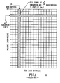
- FIG. 1 numeral 100, illustrates the two-dimensional nature of an OFDM based transmission scheme. Each small square represents a symbol. A single row (102) of the squares represents the symbols on a single subcarrier over several baud intervals or symbol intervals.
- Each column (104) of the squares represents the symbols in a single baud interval over several subcarriers. This two-dimensional representation may be referred to as a time-frequency grid.
- the symbol which is to be transmitted on the m th subcarrier during the n th baud interval will be denoted as x ( m,n ) .
- OFDM signal modulation or demodulation can be implemented with an inverse or forward Discrete Fourier Transform (DFT), respectively, as is known in the art.
- DFT Discrete Fourier Transform
- IFFT inverse fast Fourier transform
- the IFFT is computed once every baud interval, with the IFFT output representing one column of the two-dimensional grid shown in FIG. 1 .
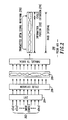
- an IFFT based OFDM modulator takes a group of symbols (202) corresponding to a single column of the above grid (i.e., symbols across multiple subcarriers, but within a single baud interval) as an input vector, computes an IFFT (204) of the input vector, then outputs the IFFT results as the OFDM signal waveform (210) (representing the symbols within one symbol (baud) interval).
- the OFDM modulator may also include a cyclic extension unit (206), which cyclically extends the output samples of the IFFT (208), as is known in the art.
- the extension is used to eliminate inter-symbol interference (ISI) and inter subcarrier interference (ICI) due to multipath delay spread channels.
- ISI inter-symbol interference
- ICI inter subcarrier interference
- the cyclic extension duration must be greater than the duration of the channel impulse response.
- a cyclically extended OFDM signal includes an information portion (212) and a cyclic extension portion (214), as is known in the art.
- the cyclic extension is a repetition of part of the information portion of the OFDM signal.
- a time interval which includes both the information portion and the cyclic extension portion is referred to as a baud interval.
- the information contained within a baud interval will be referred to as a baud or an OFDM baud.
- the signal waveform which represents the symbols in a baud interval can be referred to as an OFDM signal.
- SC-OFDM is based on the combination of the following elements/requirements:
- both the desired and co-channel interferer signal components can be received by an OFDM receiver without ISI and ICI.
- the first requirement insures that the OFDM symbol transmission time interval of co-channel interferers will coincide with the desired signal OFDM transmission time interval. With identical transmission time intervals, desired and co-channel signal components will be received with no ISI and ICI if the cyclic extension has sufficient length to absorb both delay spread and the propagation delay between co-channel transmitters.
- an SC-OFDM receiver can estimate the desired channel and co-channel interfering channel responses.
- interpolation filtering can be used to estimate the channel response, also known as the complex channel gain, of the desired signal between the locations of the orthogonal reference signals.
- the channel response of the co-channel interferers can be interpolated in a similar way to the desired signal channel response.
- Knowledge of the channel response of the desired and co-channel interfering signals can then be used by the SC-OFDM receiver in a number of ways to improve performance or monitor channel conditions.
- the measurement of the channel responses of the desired and interfering signal components is also referred to as multi-channel channel response measurement.
- the combination of the desired and co-channel interfering signals received by a receiver from a plurality of transmitters will also be referred to as a composite received signal.
- the combination of the pilot codes received by a receiver from a plurality of co-channel transmitters will also be referred to as a composite pilot code.
- the first requirement can be satisfied by synchronizing base stations (SC-OFDM transmitters, 1402, 1404, ...1406) to a common time reference such as the global positioning system (GPS) (1408) or a common wireline (1410) network clock as shown in FIG. 14 , numeral 1400.
- the second requirement can be satisfied by using either a large OFDM cyclic extension or small cells to minimize propagation delay.
- the third requirement can be satisfied by using pilot codes rather than individual pilot symbols in each OFDM slot for channel response estimation.
- a sequence length of N can provide N orthogonal pilot codes for inter-cell orthogonality. Note that the pilot codes not only enable the measurement of the channel response of co-channel interferers, but also virtually eliminate any co-channel interference from the channel response estimate of the desired signal.
- a cellular re-use pattern in accordance with a preferred embodiment of the present invention is a single cell re-use pattern with three sectors per cell as shown in FIG. 3 , numeral 300.
- a base unit (302) is located in the center of each cell, and subscriber units may be located anywhere in a cell.
- the transmission from a base unit to a subscriber unit is referred to as a downlink, while the transmission from a subscriber unit to a base unit is referred to as an uplink.
- the pilot code scheme preferably includes a pilot code allocation plan which is indicated in FIG. 3 by the shading pattern.
- the shaded sector of the center cell is allocated pilot code 1, and the primary interfering sectors of the surrounding cells are allocated the other three pilot codes, 2, 3, and 4.
- the pilot code scheme may also include pilot code re-use, as indicated in FIG. 3 . Pilot codes can be re-used in sectors which are not in adjacent cells or are not pointing toward the subscriber unit. That is, pilot codes can be re-used in sectors which transmit away from the desired sector, and in the sectors which are in the second ring of co-channel cells. The pilot code re-use is possible because the signals originating in the sectors with re-used pilot codes are significantly attenuated when they reach the receiver in the sector of the center cell.
- pilot code reuse pattern is selected such that the potentially strongest co-channel interferers have different pilot codes than the desired signal, and this property is preferably satisfied in every sector of every cell within the SC-OFDM system.
- pilot code pattern was predetermined in this example, the pilot code re-use pattern can also be determined dynamically in an SC-OFDM system.
- Techniques in the art for performing dynamic channel allocation or the like can be applied to the allocation and dynamic management of pilot codes in an SC-OFDM system. This capability allows changes to the system, such as the addition of a new cell, to be handled in a flexible and efficient manner.
- a pilot code is denoted as a vector W j where the elements, or symbols of the pilot code are denoted w i,j .
- the preferred embodiment of the pilot code scheme uses pilot codes which are orthogonal.
- the pilot code scheme uses pilot codes that are not orthogonal, but have small cross correlation values.
- the cross correlation values are said to be small i f they are smaller than the autocorrelation value of a pilot code by at least a predetermined amount.
- the predetermined amount is preferably several dB, such as 6 dB.
- a benefit of this alternate embodiment is that it may allow more than N pilot codes to be generated based a length N sequence.
- the pilot codes are not orthogonal, but have known cross correlation values.
- the known cross correlation values can be used in an SC-OFDM receiver to partially compensate for the known cross correlations in the estimation of the channel response of the desired and co-channel interfering signals.
- a benefit of this alternate embodiment is that i t may allow more than N pilot codes to be generated based a length N sequence.
- a drawback of these alternate embodiments is that the accuracy of the channel response measurements made in an SC-OFDM receiver will be lower than if orthogonal pilot codes are used.
- SC-OFDM transmitters preferably transmit with a common frame and slot format in each of the cells. Note that although a common frame and slot format is used, the contents of the slots and frames transmitted from different base units can vary.
- different base units may transmit different pilot codes in a slot, or different reference signals during a synchronization signal portion of a frame.
- the data in the slots transmitted by different base units is not related, which is a key distinguishing difference between the SC-OFDM system and paging or simulcast systems.
- SC-OFDM is used to increase spectrum efficiency and capacity
- simulcast is used to increase the area of service coverage.
- SC-OFDM uses a cyclic extension in the OFDM modulator.
- a cyclic extension is normally used in OFDM systems to eliminate ISI and ICI due to multipath delay spread.
- the cyclic extension duration is selected to be as large as the expected channel impulse response duration or delay spread.
- the cyclic extension is also used to enable the receiver to receive signals from nearby co-channel interferers without ISI and ICI. Therefore, in SC-OFDM, the cyclic extension duration is preferably selected to be as large as the sum of the base-to-base propagation delay between co-channel cells and the channel impulse response duration.
- SC-OFDM is used within a single cell of a communication system.
- a single cell can use the same frequency group in each sector. The re-use of the frequency group within each sector provides a higher spectrum efficiency within a cell.
- each sector using the frequency group in the cell would be allocated a different pilot code from a set of orthogonal pilot codes.
- the transmitters for the different sectors can either be in a single base unit or a plurality of co-located base units.
- SC-OFDM is used within a single cell of a communication system by transmitting a plurality of SC-OFDM signals through a directional antenna system.
- each SC-OFDM signal has a different pilot code from a set of orthogonal pilot codes.
- Each of these alternate embodiments can use a single base unit which generates a plurality of OFDM signals simultaneously and transmits them with sectored, distributed, or an array of antennas. A benefit of these alternate embodiments is that they avoid the need to synchronize a plurality of base units to a common time reference.
- a frame is a grouping of one or more OFDM symbol time intervals and one or more subcarrier locations.
- an OFDM symbol time interval also known as a baud interval, represents a number of symbols equal to the number of subcarriers in the OFDM modulator, as is known in the art.
- Frames are transmitted sequentially in time.
- the OFDM signals are transmitted sequentially, one baud after another.
- the OFDM modulator generates one baud at a time, with the OFDM signal in one baud representing a number of symbols equal to the number of subcarriers in the OFDM modulator. That is, the OFDM modulator generates one column of modulated data per baud and transmits the bauds sequentially in time.
- a frame and slot formatter takes user data and other symbols and formats them into the predetermined slot and frame formats. The formatter then outputs the formatted symbols to the modulator in a format of one column per baud.
- a majority of the symbols within a frame can be further grouped into a plurality of slots, where a slot is the minimum resource allocation unit for a user of the communication system.
- a slot is also a grouping of OFDM bauds and subcarrier locations.
- a slot contains a much smaller group of symbols than a frame, as is common in the art.
- a frame may also contain a grouping of one or more bauds and one or more subcarrier locations dedicated to the support of other system functions such as paging signals, broadcast signals, and synchronization signals.
- the base units using SC-OFDM transmission transmit in accordance with a common frame format.
- a common frame format includes, but is not limited to, the same frame length, the same OFDM symbol duration, subcarrier spacing, slots of the same dimensions, slots in the same locations within a frame, and pilot codes in the same locations within a slot.
- different pilot codes are used in the sectors of closest co-channel cells to the extent of the number of available pilot codes. After the available pilot codes are exhausted, they are re-used according to a pilot code re-use plan, as was described earlier and shown in FIG. 3 .
- use of portions of the frame such as the synchronization portion may be shared via time, frequency, or code division, or any combination thereof. The sharing is preferably coordinated in accordance with the pilot code re-use plan.
- a frame includes time and/or frequency regions for base units in the SC-OFDM system to transmit a synchronization or identification signal.
- This signal is a type of broadcast signal, and is preferably used to provide a known signal which the subscriber units can monitor to acquire and/or maintain timing and/or frequency synchronization.
- the frame region dedicated to this purpose i s divided into preferably orthogonal regions via time, frequency, or code orthogonality, or some combination of these. Then each base unit is assigned one of the regions for transmitting its synchronization signal.
- the assignment to these regions is done in way that is preferably similar to the way the allocation of pilot codes was done for the base units.
- a subscriber unit is able to measure the synchronization signal from the base unit in its own cell without the detrimental effects of strong co-channel interference.
- the subscriber unit is able to measure/monitor the synchronization signal from the dominant co-channel interfering sectors of the surrounding cells. This capability enables the subscriber unit to measure the relative propagation delay of the interfering signals, which directly affects the amount of phase change per subcarrier on the interfering signals after demodulation.
- the subcarrier phase difference information for an interfering signal can be accounted for in the detection algorithms in the receiver, as will be described later.
- FIGs. 4-6 , numerals 400, 500 and 600 respectively, indicate embodiments of schemes for coordinating the transmission of synchronization signals in a frame by a plurality of base units. In each case, the coordination is based in part on the pilot code scheme.
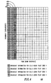
- FIG. 4 numeral 400, illustrates a preferred embodiment which includes adjacent baud intervals (402, 404, 406, 408) in a frame for the transmission of synchronization signals.
- a base unit which uses pilot code 1 transmits a synchronization signal during the first baud and null symbols (i.e., symbols with a constellation value of (0,0)) during the second, third and fourth bauds.
- a base unit which uses pilot code 2 transmits a synchronization signal during the second baud and null symbols (0) during the first, third, and fourth bauds.
- a base unit which uses pilot code 3 transmits a synchronization signal during the third baud and null symbols (0) during the first, second, and fourth bauds.
- a base unit which uses pilot code 4 transmits a synchronization signal during the fourth baud and null symbols (0) during the first, second, and third bauds.
- the synchronization signal transmitted by a base unit is not required to be an OFDM signal. Any signal which is time-limited so as to fit in a baud duration and band-limited so as to fit in the frequency band spanned by the subcarriers can be used. Also, although the bauds for the transmission of synchronization signals are adjacent in this embodiment, these bauds are not required to be adjacent in general. According to this embodiment, the composite received signal for a receiver receiving during one of the four synchronization baud intervals includes null signals from three base units and a synchronization signal from one base unit.
- FIG. 5 illustrates to an alternate embodiment of a scheme for coordinating the transmission of synchronization signals in a frame by a plurality of base units.
- a set of 4 subcarriers (502, 504, 506, 508), as indicated by shading in the figure, are for the transmission of synchronization signals by a plurality of base units.
- a base unit which uses pilot code 1 transmits synchronization symbols in the first shaded subcarrier and null symbols (0) in the second, third, and fourth shaded subcarriers.
- a base unit which uses pilot code 2 transmits synchronization symbols in the second shaded subcarrier and null symbols (0) in the first, third, and fourth shaded subcarriers.
- a base unit which uses pilot code 3 transmits synchronization symbols in the third shaded subcarrier and null symbols (0) in the first, second, and fourth shaded subcarriers.
- a base unit which uses pilot code 4 transmits synchronization symbols in the fourth shaded subcarrier and null symbols (0) in the first, second, and third shaded subcarriers.
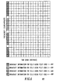
- FIG. 6 illustrates another alternate embodiment of a scheme for coordinating the transmission of synchronization signals in a frame by a plurality of base units.
- the symbols, or subcarriers, within a single baud are divided into 4 groups (602, 604, 606, 608), as indicated by the 4 shaded areas of the first baud.
- These groups within the first baud are for the transmission of synchronization signals by a plurality of base units.
- the unshaded symbols in the first baud are optional null symbols which may be used to provide frequency guard space between the groups.
- a base unit which uses pilot code 1 transmits synchronization symbols in the first shaded group of subcarriers and null symbols (0) in the second, third, and fourth groups of shaded subcarriers.
- a base unit which uses pilot code 2 transmits synchronization symbols in the second shaded group of subcarriers and null symbols (0) in the first, third, and fourth groups of shaded subcarriers.
- a base unit which uses pilot code 3 transmits synchronization symbols in the third shaded group of subcarriers and null symbols (0) in the first, second, and fourth groups of shaded subcarriers.
- a base unit which uses pilot code 4 transmits synchronization symbols in the fourth shaded group of subcarriers and null symbols (0) in the first, second, and third groups of shaded subcarriers.
- Each of these embodiments of a scheme for coordinating the transmission of synchronization signals in a frame by a plurality of base units avoids co-channel interference on the synchronization signal from base units which use different pilot codes.
- These embodiments can also be combined, as necessary, to coordinate a larger number of base unit synchronization signal transmissions.
- These embodiments can also be applied to coordinate the transmission of synchronization or other signals by a plurality of subscriber units.
- the scheme is not limited to the this application.
- the coordination scheme is also directly applicable to the transmission of paging, system information, broadcast signals, or other information.
- the description was given for the case of coordinating four transmissions, similar embodiments for larger or smaller numbers of transmissions are merely variations of the presented embodiments.
- the coordination scheme can also easily be extended to coordinate the transmission of synchronization signals over a plurality of frames. For example, a frame could include a single baud for the transmission of a synchronization signal, with the usage of the sync baud coordinated for four base units over four frames.
- a slot consists of a predetermined number of adjacent OFDM symbol time intervals and subcarriers. Slots contain one or more pilot codes according to the pilot code allocations to the cells, as described earlier.
- the pilot code scheme does not require the pilot codes to be the same in each transmitted slot as long as the base units in the SC-OFDM system step through the available pilot codes in a coordinated fashion so as to maintain the orthogonality and avoid code collisions.
- different pilot codes can be used in each pilot code position as long as the pilot codes are selected in a coordinated fashion among the base units in the SC-OFDM system.
- This coordination or allocation can be treated as "code hopping", and any techniques known in the art for implementing orthogonal hopping patterns can be applied to the pilot code selection process as a part of the pilot code scheme.
- Another way to handle the use of different pilot codes in a single transmitter is to define a group of pilot code sets where a pilot code set includes a plurality of pilot codes in a predetermined order.
- An example of a pilot code set is ⁇ W 1 W 2 W 3 W 4 ⁇ .
- the group of pilot code sets are chosen such that the n th pilot code of any pilot code set which is a member of the group is orthogonal to the nth pilot code of the other code sets in the group.
- pilot code sets with this property is ⁇ W 1 W 2 W 3 W 4 ⁇ , ⁇ W 2 W 3 W 4 W 1 ⁇ , ⁇ W 3 W 4 W 1 W 2 ⁇ , ⁇ W 4 W, W 2 W 3 ⁇ .
- the pilot code sets would be allocated to transmitters using a scheme which is essentially similar to the pilot code scheme.
- a slot is intended to be the minimum unit which can be allocated to a user for a communication session.
- a slot contains at least one pilot code.
- a receiver correlates the received pilot code with the pilot code of the desired signal and with the pilot codes of the co-channel interfering signals in order to measure the channel response of the desired signal and the co-channel interfering signals.
- a slot contains a plurality of pilot codes to enable the use of interpolation filtering to follow variations in the channel conditions over the slot.
- a slot consists of 6 symbol intervals in time (6 bauds) (702), and 11 subcarriers (704) in frequency as shown in FIG. 7 , numeral 700.
- channel response estimates can be computed on the subcarriers containing a pilot code (w 1,j , w 2,j w 3,j w 4,j ), and then interpolation filtering can be applied across the subcarriers.
- This slot format is best used in environments which are not expected to change significantly over the 6 baud duration of the slot.
- the SC-OFDM system preferably includes convolutional coding for error correction.
- Decoding i s preferably implemented with soft decision decoding.
- the pilot code consists of symbols from a constellation such as BPSK or QPSK.
- the pilot code includes constellation symbols and null symbols. When null symbols are included, i t is preferred to increase the magnitude of the constellation symbols in the pilot code to maintain the same estimation accuracy in a noisy channel.
- W 1 ⁇ 1 1 1 1 ⁇ T
- W 2 ⁇ 1 - 1 1 - 1 ⁇ T
- W 3 ⁇ 1 1 - 1 - 1 ⁇ T
- W 4 ⁇ 1 - 1 - 1 ⁇ T
- a receiver receiving an SC-OFDM transmission measures the channel response of the desired signal at a pilot code location, that is, the group of symbol locations within a slot which encompass a pilot code, by cross correlating the received, demodulated signals at the pilot code location with a stored, known pilot code for the desired signal.
- the portion of the received signals containing a pilot code is also referred to as a composite pilot code because the received pilot code is actually the weighted sum of a plurality of pilot codes from a plurality of SC-OFDM transmitters, where the weights are the respective channel responses between each SC-OFDM transmitter and the given SC-OFDM receiver.
- the cross correlation process is repeated for each pilot code location in a slot.
- Interpolation filtering is then applied to the channel response measurements to generate channel response estimates for each symbol location in the slot.
- the receiver also measures the channel response of a co-channel interfering signal at a pilot code location by cross correlating the composite pilot code with a stored pilot code which is different than the pilot code for the desired signal.
- Interpolation filtering is then applied to the interferer channel response measurements to generate interferer channel response estimates for each symbol location in the slot.
- the interferer channel response measurement and interpolation filtering process is repeated for each pilot code in the orthogonal pilot code set which is not the pilot code of the desired signal.
- the measurement of the channel response of signals from a plurality of transmitters is also called multi-channel channel response measurement.
- the symbols characterizing a pilot code are placed in adjacent baud/symbol intervals and/or adjacent subcarriers within the slot.
- the symbols characterizing a pilot code are dispersed in time or frequency, or both, within the slot.
- An example using dispersed symbols is shown in FIG. 8 , numeral 800.
- Two-dimensional (time and frequency) (802, 804) interpolation filtering can be used with this slot structure in order to track variations in the channel response in both time and frequency.
- the orthogonality of the pilot codes will begin to degrade. As the orthogonality degrades, the accuracy of the channel response measurements will decrease accordingly.
- propagation delay is a non-negligible fraction of the symbol duration (e.g. > 1%)
- An alternate embodiment places the symbols of a pilot code in a combination of multiple symbol periods and multiple subcarriers (1002), as shown in FIG. 10 , numeral 1000.
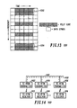
- FIG. 11 Another alternate embodiment of a slot format places only a single pilot code in a slot (1102), as shown in FIG. 11 , numeral 1100.
- This alternate slot format is useful when the channel response is not expected to change significantly over the slot.
- a benefit of this alternate slot format is that no interpolation filtering is needed, which leads to lower complexity in the receiver.
- Different data rates are supported in the system by assigning different numbers of slots to a user. Multiple slots are allocated either in time, frequency, or both. The multiple slots do not need to be adjacent in time or frequency. It is preferable for the assigned slots to be separated in time and/or frequency in order to realize a time and frequency diversity effect, respectively.
- the maximum data rate is provided by assigning all slots to a single user. The data rate provided to a user can be different during different communication sessions, or may even vary during the same communication session.
- the data symbols in a slot are based on a QPSK constellation, which represents two bits per data symbol.
- the data symbols in a slot are based on a constellation which provides the largest number of bits per symbol that can be used while still providing an adequate bit error rate (BER) performance.
- BER bit error rate
- the criterion for adequate BER performance varies with the application.
- the constellation can change on a slot by slot basis to match the current channel conditions, or can be predetermined based on the expected co-channel interference levels.
- only the slots which have been assigned to active users/subscriber units are modulated and transmitted.
- the benefit of this approach is that the amount of co-channel interference that is passed into the surrounding cells is minimized.
- This method is implemented by filling all slots or subcarriers which are not assigned with null symbols (i.e., symbols with a constellation value of (0,0)).
- the pilot codes in each slot are transmitted even when the slot is not assigned to a user. This method provides additional pilot codes outside the slots assigned to a particular user which can be used to increase the number of channel response measurements used in the channel response interpolation process.
- FIG. 12 shows an example of a frame which includes slots for data transmission and time regions for base units in the SC-OFDM system to transmit a synchronization signal (1202).
- the frame includes four adjacent baud intervals at the beginning of the frame for the transmission of synchronization signals by a plurality of base units, as described earlier.
- the rest of the frame contains slots which may be assigned to carry data for users of the communication system.
- a slot (1206) spans four baud intervals and five subcarriers, as indicated by the bold lined boxes.
- a slot includes two pilot codes (1204), each of length two. This pilot code length is smaller than preferred, but it is used in this example for illustrative purposes.
- the frame contains 5 slots in the time dimension and 5 slots in the frequency dimension, for a total of 25 slots in a frame. Slots which are not shaded illustrate slots that are not allocated to a user. These slots are filled with null symbols, and can be viewed as not actually being transmitted.
- the receiver can acquire initial synchronization to the system frequency and timing by searching for a signal having the properties of one of the synchronization signals transmitted by the base units. (examples include correlation, differential correlation).
- the synchronization signals from multiple base units can be monitored to determine the relative signal quality of the different base units. This information can then be used to determine which of the base units would provide the best signal quality, and which base unit to communicate with in a communication session.
- the synchronization signals from the plurality of base units are preferably still monitored to enable the subscriber unit to monitor the overall signal quality, including signal power, interference power, C/I, C/N, etc. This information can be used in a number of ways to improve system quality and reliability, such as mobile assisted handoff.
- interference suppression techniques can be used to improve the performance of SC-OFDM receivers compared to conventional OFDM receivers.
- the receiver is synchronized to the symbol timing and center frequency of the received signal. This can be accomplished using one of the OFDM synchronization algorithms known in the art.
- the received signal has been sampled and processed by an FFT demodulator to provide a baseband received signal with 1 complex sample per subcarrier per symbol interval, as is known in the art.
- the received signal is also referred to as a composite received signal in SC-OFDM, because the received signal consists of received signals from a plurality of SC-OFDM transmitters.
- An output of the FFT demodulator is also referred to as a composite symbol, because it encompasses a combination of transmitted symbols from a plurality of SC-OFDM transmitters.
- a composite symbol has a component from each of the plurality of SC-OFDM transmitters.
- the baseband received composite signals are parsed into received slots consisting of pilot code portions and composite data portions according to the predetermined slot format.
- a pilot code portion includes the pilot symbol locations which encompass a composite pilot code.
- the pilot code portion is also referred to as a composite pilot code portion.
- a multi-channel channel response estimator is used to estimate the channel response of signals from a plurality of SC-OFDM transmitters.
- the SC-OFDM receiver correlates a composite pilot code portion of a received slot with a known, stored, pilot code for the desired signal. For example, a receiver in a sector which has been allocated pilot code 1 correlates a composite pilot code portion of the received slot with a locally stored copy of pilot code 1. If there are multiple pilot codes in a slot, the correlation is preferably performed for each composite pilot code portion of the received slot.
- the channel response measurements are preferably filtered with an interpolation filter to provide desired signal channel response measurements for both pilot code portions and the data portions of the slot.
- This interpolation can also include desired signal channel response measurements from adjacent slots if the user is assigned a plurality of adjacent slots.
- the composite pilot code portion of a received slot is also correlated with the pilot codes which are not assigned to the desired signal.
- the composite pilot code is correlated with a locally stored copy of pilot codes 2, 3, and 4. The result of these correlations provide channel response measurements for co-channel interfering signals using pilot codes 2, 3, and 4, respectively. If there are multiple pilot codes in a slot, the correlations are preferably repeated for each pilot code portion of the received slot.
- the channel response measurements for one the co-channel interfering signal are preferably filtered with an interpolation filter to provide co-channel interfering signal channel response measurements for both pilot code portions and the data portions of the slot.
- This interpolation filtering is preferably repeated for each of the co-channel interfering signal pilot codes to provide a set of interpolated co-channel interferer channel response measurements.
- the channel response is not filtered with the interpolation filter in order to reduce processing complexity.
- an SC-OFDM receiver unit with multiple antennas and receivers uses MMSE diversity combining to combine the signals received on each antenna.
- the impairments on the received SC-OFDM signal typically include multipath fading, additive white Gaussian noise (AWGN), and co-channel interference.
- AWGN additive white Gaussian noise
- the goal of MMSE diversity combining is to minimize the mean squared error between the combiner outputs and the symbols transmitted by the desired transmitter. To this extent, the signals from the multiple antennas are combined in such a way that desired components add constructively and/or interfering components add destructively.
- two branch diversity reception is assumed and the co-channel interference is modeled as SC-OFDM signals from a single co-channel SC-OFDM transmitter. This model was chosen to simplify notation and emphasize the essential aspects of MMSE diversity combining. It is straightforward to extend the model to include additional antenna branches and/or additional SC-OFDM co-channel interfering signals.
- m is the subcarrier index
- n is the baud index
- x 1 ( m,n ) is the data symbol originating from the desired transmitter
- x 2 ( m,n ) is the data symbol originating from the interfering transmitter.
- the Gaussian noise terms on the first t and second diversity branches are given by ⁇ 1 ( m,n ) and ⁇ 2 ( m,n ) , respectively, with E
- 2 ⁇ 1 2
- 2 ⁇ 2 2
- and E v 1 * m ⁇ n ⁇ v 2 m ⁇ n 0.
- the instantaneous channel responses are modeled by g k,p ( m,n ) , where k differentiates between the desired and interfering transmitters and p differentiates between the two diversity branches.
- x k ( m,n ) represents a QPSK data symbol having a unit power constellation (
- 2 1 , ⁇ m, n, and k ).
- the SGOFDM receiver When MMSE diversity combining a set of received signals, the SGOFDM receiver first forms a signal covariance matrix and signal steering vector based on the appropriate desired and interfering channel estimates. As discussed earlier, these estimates can be obtained from a multi-channel channel response measurement based on the desired and interfering transmitters' pilot codes.
- the expectation can be approximated using a sample average over any amount of time over which the channel is constant, as is known in the art.
- x d ( m,n ) is a reference signal correlated with the desired data signal and uncorrelated with the interfering data signal.
- the expectation in the signal steering vector computation can be approximated using a sample average over any amount of time over which the channel is constant.
- the denominator in the above equation, ⁇ w 2 m ⁇ n equals the mean squared error resulting from the combining process. Dividing by this term provides a channel quality weighting, facilitating soft decision decoding within the receiver. This term can be easily derived using the aforementioned pilot codes.
- the denominator in the above equation, ⁇ w 2 m ⁇ n equals another channel quality estimate designed to allow soft decision decoding and is also derived using the pilot codes.
- the denominator in the above equation, ⁇ w 2 m ⁇ n equals one.
- the rate at which the weights need to be recomputed depends on the rate at which the channel changes. In faster channels with higher Doppler rates, the weights need to be recomputed more often. Conversely, in slower channels with lower Doppler rates, the same weights can be used for longer periods of time.
- An alternate embodiment of an SC-OFDM receiver unit with multiple antennas and receivers uses diversity combining with signal quality weighting.
- the impairments on the received SC-OFDM signal typically include multipath fading, additive white Gaussian noise (AWGN), and co-channel interference.
- the diversity combining weights include information relating to both the noise power and the co-channel interference level.
- two branch diversity reception is assumed and the co-channel interference is modeled as SC-OFDM signals from a single co-channel SC-OFDM transmitter. This model was chosen to simplify notation and emphasize the essential aspects of the combining approach. However, it is straightforward to extend the model to include additional antenna branches and multiple SC-OFDM co-channel interferers.
- m is the subcarrier index
- n is the baud index
- x 1 ( m,n ) is the desired data symbol originating from the desired transmitter
- x 2 ( m m,n ) is the desired data symbol originating from the desired transmitter
- the channel responses are modeled by g k,p ( m,n ), where k differentiates between the desired and interfering transmitters and p differentiates between the two diversity branches.
- x k ( m,n ) represents a QPSK data symbol having a unit power constellation (
- 2 1, ⁇ m , n , and k ).
- the demodulated sample from each antenna is first multiplied by the conjugate of its corresponding estimated desired signal channel response, g 1, p ( m,n ), and is then divided by an estimate of the instantaneous interference power plus noise power.
- the desired and co-channel interference estimates can be obtained from the pilot codes which are included in each slot.
- the noise power can be either be estimated or be known based on the noise figure of the receiver.
- joint detection Another preferred embodiment of a reception scheme for SC-OFDM is joint detection, which is sometimes also referred to as multi-user detection.
- a benefit of joint detection as compared to the diversity reception schemes described earlier is that joint detection does not require the use of diversity reception. However, it should be understood that diversity reception is still beneficial even when joint detection is employed.
- co-channel interfering signal components can be treated as joint desired signals in the detection process. That is, the sum of the desired and interfering signal components can be treated as a new desired signal called the joint desired signal.
- the joint desired signal is detected using a maximum likelihood or minimum Euclidean distance joint detector. Since there is no ISI or ICI, the joint detector operates on a symbol-by-symbol basis which results in a joint detector with relatively low complexity.
- y m ⁇ n - ⁇ k 1 K x ⁇ k m ⁇ n ⁇ g ⁇ k m ⁇ n ⁇
- m is the subcarrier index
- n is the baud interval index
- y ( m,n ) is the received signal
- ⁇ k ⁇ x ⁇ k m ⁇ n ⁇ g ⁇ k m ⁇ n represents the joint desired signal.
- k is the transmitter index
- K is the total number of transmitters being jointly detected
- ⁇ k ( m,n ) is the estimated channel response for the k th transmitter
- x ⁇ k ( m,n ) is the estimated value of the transmitted symbol from the k th transmitter.
- ⁇ k ( m,n ) can be estimated based on the SC-OFDM orthogonal pilot code scheme with a multi-channel channel response measurement.
- the Euclidean distance metric is extended to encompass the signals from all of the diversity branches.
- y p m ⁇ n - ⁇ k 1 K x ⁇ k m ⁇ n ⁇ g ⁇ . pk m ⁇ n ⁇
- p is the index of the diversity branch
- ⁇ p 2 is the noise variance on the p th branch.
- the measured channel responses of the desired and interfering signals are used to estimate signal quality.
- the signal quality information is used to improve other aspects of receiver operation. These aspects include, but are not limited to, soft decision weighting for a decoder, mobile assisted handoff, bit error rate estimation, interference power estimation, and desired signal power estimation.
- an OFDM receiver estimates a symbol timing phase.
- the symbol timing phase determines the boundaries on a block of f samples which are passed to the FFT demodulator. If the transmitted OFDM signal includes a cyclic extension portion, an offset in the timing phase at the receiver does not necessarily cause ISI and ICI. However, even if ISI and ICI are not introduced, a offset in the symbol timing phase causes an additional phase difference between the demodulated signals from different subcarriers. This additional phase difference, which is introduced by an offset in the timing phase, will be referred to as subcarrier phase difference.
- subcarrier phase difference is used to refer to the portion of phase difference that is due to the symbol timing phase used for demodulation.
- the subcarrier phase difference can be shown to be a phase difference which is constant between adjacent subcarriers.
- subcarrier phase difference can degrade the performance of an OFDM receiver.
- One such case arises when the information in an OFDM signal is differentially encoded across adjacent subcarriers, such as DQPSK where the phase change representing an information symbol is encoded across two adjacent subcarriers.
- the subcarrier phase difference upon reception and demodulation, results in a phase bias in the output of the differential detector in the receiver. This phase bias may degrade the bit error rate performance of the receiver.
- the OFDM signal includes known symbols on a plurality of subcarriers to support channel response measurement and subsequent interpolation filtering across a plurality of subcarriers.
- subcarrier phase difference is indistinguishable from multipath delay spread induced channel variations.
- subcarrier phase difference appears as additional channel response variation in the interpolation filtering and this may reduce the accuracy of the interpolated channel response.
- the reduced accuracy of the interpolated channel response may degrade the bit error rate performance of the receiver.
- an OFDM receiver estimates the adjacent-subcarriers phase difference and compensates for the estimated adjacent-subcarriers phase difference in the detection process, which may include channel response measurement and interpolation for coherent detection.
- the estimate denoted as ⁇ adj
- the estimate can be obtained by measuring an average adjacent-subcarriers phase difference based on a received signal containing known data such as the broadcast synchronization signal described earlier or known symbols within one or more slots.
- the measurement can be based on unknown valued data symbols in a slot. In the latter case, a nonlinearity can be used to remove the portion of the phase due to the value of the data symbol.
- the measurement of the average adjacent-subcarriers phase difference is preferably made over several adjacent subcarriers and is averaged over a plurality of baud intervals to suppress noise and suppress phase variations which are caused by multipath delay spread.
- the OFDM signal includes known symbols on a plurality of subcarriers to support channel response measurement and subsequent interpolation filtering across a plurality of subcarriers
- compensation is preferably incorporated into the detection process by modifying the pilot interpolation filtering coefficients which are used to generate the interpolated channel response measurements used for detection. As shown in the equation below, these coefficients become a function of the measured or estimated adjacent-subcarriers phase difference, which is denoted as ⁇ adj.
- ⁇ ( m,n ) is an interpolated channel response measurement at the m th subcarrier and n th baud interval generated by interpolation filtering between the channel response measurements, ⁇ p ( m p ,n p ), at the m p th subcarriers and n p th baud intervals generated using known symbols.
- the interpolation filtering coefficients, h p (m,n), are preferably predetermined for each interpolated channel response measurement location (m th subcarrier and n th baud interval) given a set of known symbol locations (m p th subcarriers and n p th baud intervals, where 1 p P).
- the phase compensation term, exp(- j ( m p - m ) ⁇ adj ) compensates for the phase difference between each known symbol location and the location of the interpolated channel response measurement, where (m p -m) is the number of subcarriers between the two locations and ⁇ adj is the measured adjacent-subcarriers phase difference as described earlier.
- compensation is implemented as a phase modification of the demodulated signal on each subcarrier prior to channel response measurement and interpolation filtering.
- the phase modification for each subcarrier is based on the measured adjacent-subcarriers phase difference and the equation for subcarrier phase difference given earlier and may be performed by an adjacent-subcarriers phase difference compensation unit.
- the algebraic sign of the phase modification value is selected to cancel the subcarrier phase difference on the demodulated signal.
- the phase modification is preferably implemented in a detector which includes a conventional differential detector followed by a phase modifier which modifies the phase of the output of the differential detector.
- the value of the differential phase modication is based on the measured adjacent-subcarriers phase difference.
- the algebraic sign of the differential phase modication value is selected to cancel the measured adjacent-subcarriers phase difference.
- the same differential phase modification value can be used for a plurality of differential detector outputs.
- compensation is implemented as a phase modification of the demodulated signal on each subcarrier prior to differential detection.
- a received composite SC-OFDM signal can be viewed as the sum of indivdually weighted and delayed SC-OFDM signals originating from at least two SGOFDM transmitters.
- the weights correspond to the appropriate complex channel gain and the delays correspond to the propagation delay.
- each link will likely have a different propagation delay and that the SC-OFDM receiver only chooses a single symbol timing phase to demodulate the entire received composite SC-OFDM signal, each component of this composite SC-OFDM signal will likely have a different adjacent-subcarriers phase difference after demodulation.
- the adjacent-subcarriers phase difference is measured for each component of a given composite SC-OFDM signal.
- the measurement of a plurality of adjacent-subcarriers phase differences is also referred to as multi-channel adjacent-subcarriers phase difference measurement.
- these measurements can be performed using the techniques described above for OFDM receivers.
- a preferred embodiment of an SC-OFDM receiver also uses interpolation filtering in the detection process to calculate channel response measurements at subcarriers which do not contain pilot codes. Interpolation filtering is preferably performed separately for each component of the received composite SC-OFDM signal and the adjacent-subcarriers phase difference for each component is preferably compensated for during the corresponding interpolation filtering process. For each component, this interpolation and compensation can be accomplished in a manner similar to that described above for OFDM receivers.
- the adjacent-subcarriers phase difference is measured only for a single component of a given composite SC-OFDM signal.
- this single component corresponds to the SC-OFDM signal originating from the SC-OFDM transmitter in the same cell as the given SC-OFDM receiver and, as such, is known as the desired signal component.
- This embodiment of an SC-OFDM receiver also uses interpolation filtering in the detection process to calculate channel response measurments at subcarrier locations which do not contain pilot codes. However, only the interpolation filtering for the desired component compensates for the appropriate adjacent-subcarriers phase difference.
- the interpolation filtering only interpolates between either magnitudes or powers of the channel response measurements at each pilot code location effectively ignoring any subcarrier phase differences.
- the adjacent-subcarriers phase difference is measured only for the desired component of a given composite SC-OFDM signal.
- Interpolation filtering is also used in the detection process to calculate channel response measurments at subcarrier locations which do not contain pilot codes. In this case, however, interpolation filtering and subsequent adjcacent phase difference compensation is only used for the desired component of the given composite SC-OFDM signal. No form of interpolation filtering is used for the remaining components of the given composite SC-OFDM signal.
- the adjacent-subcarriers phase difference is measured only for the desired component of an SC-OFDM receiver.
- This subcarrier phase difference for the desired component is compensated for prior to the channel response measurement and interpolation filtering processes. As a result, no compensation is necessary during the detection process. Moreover, no compensation i s performed for the adjacent-subcarriers phase difference of the remaining components of the composite SC-OFDM signal.
- Subcarrier phase difference which is the portion of the phase difference between demodulated signals on different subcarriers difference attributable to the choice of symbol timing phase, was described in the preceding several paragraphs.
- the measurement and compensation of subcarrier phase difference for OFDM and SC-OFDM receivers was also described.
- a symbol timing shift introduces a linear variation in the subcarrier phase across subcarriers, similar to the way a frequency offset causes a linear variation in the phase of time domain single carrier signals.
- additional embodiments of the measurement and compensation of subcarrier phase difference in OFDM signals may be based on methods in the art for measuring and compensating a frequency offset in time domain signals.
- the techniques need to be applied to the frequency domain signal. That is, they are applied to the signals across subcarriers rather than across time.
- SC-OFDM transmission scheme
- SC-OFDM is also applicable to uplink transmissions.
- Uplink transmissions may originate from mobile subscriber units which are not connected to a common network clock signal. Therefore, a different method is needed to synchronize uplink transmissions to a common time reference.
- an uplink transmitter in a subscriber unit determines transmit timing based on a closed loop timing adjustment scheme. Such closed loop timing adjustment schemes are known in the art.
- the receiver in a base unit measures a timing offset of a received uplink transmission from a subscriber unit.
- the timing offset is obtained by comparing the timing of the received signal with the time reference of the base unit.
- the timing offset value is transmitted to the subscriber unit and the subscriber unit adjusts its time reference for transmission to coincide with the time reference of the base unit.
- An important aspect of a closed loop timing adjustment scheme is that the reference clock of the subscriber unit will be adjusted differently based on the distance between the subscriber unit and the base unit. As a result, two properly adjusted subscriber units in the same sector that are located at different distances from the base unit will transmit at different times because of a difference in propagation delay. Their uplink transmissions will arrive at the base unit simultaneously in accordance with the time reference of the base unit. Therefore, for uplink transmissions, the transmission time reference of subscriber units is not necessarily the same. However, the transmission times are still defined to be synchronized because they are adjusted such that uplink transmissions are received by the base unit with timing that coincides with the time reference of the base unit.
- a pilot code scheme for the uplink can be made very similar to the pilot code scheme of the downlink. For example, a subscriber unit can use the same pilot code for uplink transmission as was used for downlink reception. A different pilot code can be used for uplink transmission, but the use of pilot codes in co-channel sectors must be coordinated by an uplink pilot code re-use pattern.
- the adjacent-subcarriers phase difference is measured based on the pilot codes within an uplink slot. If interpolation is used across subcarriers, the frequency spacing of some pilot codes in an uplink slot is preferably made small so that adjacent-subcarriers phase difference can be measured without phase wraparound effects.
- FIG. 13 is a graphical representation of an embodiment of a slot for an uplink wherein a pilot code is placed on adjacent subcarriers for first and second subcarriers (1302), and the eleventh and twelfth subcarriers (1304).
- This slot structure contains 12 subcarriers and 6 symbol intervals.
- the slot contains two sets of pilot codes located on adjacent subcarriers to enable the adjacent-subcarriers phase difference to be measured without phase wraparound effects.
- FIG. 14 is a block diagram of one embodiment of an SC-OFDM system in accordance with the present invention.
- the synchronous coherent orthogonal frequency division multiplexing, SC-OFDM, system includes a plurality of SC-OFDM transmitters (1402, 1404, ...1406) and a plurality of SC-OFDM receivers (1412, 1414, ...1416).
- Each SC-OFDM transmitter (1402, 1404, ...1406) is synchronized to a reference, where the reference is derived from a common source, for transmitting SC-OFDM signals.
- the common reference may be a network clock connected by a wireline (1410) or may be a global positioning system (1408).
- the SC-OFDM receivers (1412, 1414, ...1416) are arranged to receive the SC-OFDM signals from at least one of the plurality of SC-OFDM transmitters (1402, 1404, ...1406).
- the SC-OFDM signals each have a cyclic extension, and the SC-OFDM signals from each SC-OFDM transmitter (1402, 1404, ...1406) include at least one pilot code in accordance with a predetermined pilot code scheme.
- the predetermined pilot code scheme is typically a scheme such as those described above.
- the cyclic extension generally has a duration based at least in part on inter-SC-OFDM transmitter propagation delay.
- the at least one pilot code typically includes a sequence from a set of sequences with minimal/zero/known cross-correlation, and the predetermined pilot code scheme places each pilot code in a predetermined set of symbol locations. Where a number of SC-OFDM transmitters exceeds a number of sequences in the set of sequences, a same pilot code is utilized by at least two SC-OFDM transmitters. Either each SC-OFDM transmitter is in a base unit and each SC-OFDM receiver is in a subscriber unit, or each SC-OFDM transmitter is in a subscriber unit and each SC-OFDM receiver is in a base unit, or, alternatively, the base unit and subscriber unit both have at least one SC-OFDM transmitter and an SC-OFDM receiver.
- the base unit further includes a transmitter
- the subscriber unit further includes a receiver
- the reference derived from the common source is based on a closed loop timing adjustment scheme.
- the cyclic extension may further be based on a duration of a channel impulse response.
- the plurality of SC-OFDM transmitters may be co-located.
- the SC-OFDM transmitters and SC-OFDM receivers are typically implemented in one of: A) an application-specific integrated circuit (ASIC); B) a digital signal processor (DSP); C) a processor; D) code; and E) a combination of at least two of A-D.
- ASIC application-specific integrated circuit
- DSP digital signal processor
- C processor
- D code
- E a combination of at least two of A-D.
- FIG. 15 is a block diagram of a base unit (1502) having an SC-OFDM transmitter/ASIC/DSP/processor/code (1504) synchronized to a reference where the reference is derived from a common source, for transmitting SC-OFDM signals in accordance with the present invention.
- the SC-OFDM transmitter/ASIC/DSP/processor/code (1504) includes a modulator (1506), a cyclic extension unit (1508), and a synchronizing unit (1510).
- the modulator (1506) is coupled to receive predetermined pilot codes and data and is used for providing at least one OFDM signal in accordance with a predetermined pilot code scheme.
- the cyclic extension unit (1508) is coupled to the modulator (1506) and is used for extending the at least one OFDM signal using a cyclic extension.
- the synchronizing unit (1510) is coupled to the cyclic extension unit (1508) and to receive a time reference signal.
- the synchronizing unit (1510) is utilized for deriving a local reference signal from the time reference signal and synchronizing transmission of an at least one SC-OFDM signal of the SC-OFDM transmitter in accordance with the local reference signal.
- Each SC-OFDM signal has a cyclic extension, and each SC-OFDM signal from the SC-OFDM transmitter includes at least one pilot code in accordance with the predetermined pilot code scheme.
- the cyclic extension may have a duration based at least in part on inter-SC-OFDM transmitter propagation delay, and where selected, may further be based on a duration of a channel impulse response.
- the common source for the SC-OFDM transmitter is typically one of: a global positioning system; and a wireline network clock.
- the at least one pilot code generally includes a sequence from a set of sequences with minimal/zero/known cross-correlation and the predetermined pilot code scheme places each pilot code in a predetermined set of symbol locations.
- the predetermined set of symbol locations are typically the same as a predetermined set of symbol locations for another base unit containing another SC-OFDM transmitter.
- a plurality of SC-OFDM transmitters may be arranged to be coupled to a directional antenna system.
- the plurality of SC-OFDM transmitters may each use a different pilot code.
- the SC-OFDM transmitter may, where selected, transmit at least one of: synchronization signals and identification signals. At least one of: the synchronization signals and the identification signals may typically be one of: A) non-interfering with a synchronization/identification signal from another SC-OFDM transmitter; and B) separable from a synchronization/identification signal from another SC-OFDM transmitter. Where selected, the SC-OFDM transmitter may transmit at least one of the synchronization signal and the identification signal at a different time/frequency/code than the synchronization/identification signal transmitted by the other SC-OFDM transmitter.
- the predetermined pilot codes and data may be spread across a frequency band in a set of predetermined frequency locations and modulated to form the at least one SC-OFDM signal.
- the predetermined pilot codes and data are moved from the set of predetermined frequency locations to another set of predetermined frequency locations according to a predetermined frequency hopping method.
- any or all of the modulator, cyclic extension unit, and/or synchronizing unit may be implemented in one of: A) an application-specific integrated circuit; B) a digital signal processor; C) a processor; D) code; and E) a combination of at least two of A-D.
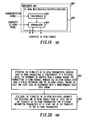
- FIG. 16 is a block diagram of one embodiment of a base unit/subscriber unit (1602) having an SC-OFDM receiver/ASIC/DSP/processor/code (1604) for receiving SC-OFDM signals in accordance with the present invention.
- the SC-OFDM receiver/ASIC/DSP/processor/code (1604) is arranged to receive at least one composite SC-OFDM signal demodulated and parsed into a plurality of composite SC-OFDM symbols and at least one composite SC-OFDM pilot code.
- the SC-OFDM receiver/ASIC/DSP/processor/code (1604) includes A) a multi-channel channel response measurement unit (1606), arranged to receive the at least one composite SC-OFDM pilot code, for computing channel response measurements for a plurality of components of the composite SC-OFDM signal based on a plurality of associated pilot codes, and B) a detector (1608), coupled to the multi-channel channel response measurement unit (1606) and to receive at least one of the plurality of composite SC-OFDM symbols, for detecting at least one symbol component from the at least one composite SC-OFDM symbol based on the channel response measurement/measurements and the at least one composite SC-OFDM symbol.
- the base unit may further include a transmitter for providing a common source based on a closed loop timing adjustment scheme.
- the detector may be selected to provide the at least one symbol component as a soft decision.
- a synchronization unit (1610) having a synchronization signal input may be coupled to the multi-channel response measurement unit (1606) for synchronizing receiver timing to a baud interval timing of a received synchronization signal, preferably an SC-OFDM signal.
- any or all of the multi-channel channel response measurement unit (1606), the detector (1608) and/or the synchronizing unit (1610) may be implemented in one of: A) an application-specific integrated circuit; B) a digital signal processor; C) a processor; D) code; and E) a combination of at least two of A-D.
- FIG. 17 is a block diagram of one embodiment of a base unit/subscriber unit with diversity antennas, having an SC-OFDM receiver unit/ASIC/DSP/processor/code (1704) in accordance with the present invention.
- the base unit has a synchronous coherent orthogonal frequency division multiplexing, SC-OFDM, receiver unit/ASIC/DSP/processor/ code (1704) having a plurality of diversity antennas arranged to receive a plurality of composite SC-OFDM signals demodulated and parsed into a plurality of composite SC-OFDM symbols and a plurality of composite SC-OFDM pilot codes.
- SC-OFDM synchronous coherent orthogonal frequency division multiplexing
- the SC-OFDM receiver unit/ASIC/DSP/processor/code (1704) includes: a plurality of multi-channel channel response measurement units (1706, 1708, ..., 1710), each arranged to receive at least one composite SC-OFDM pilot code and a plurality of composite SC-OFDM symbols, for computing channel response measurements for a plurality of components for each of the plurality of composite SC-OFDM signals based on a plurality of associated pilot codes, and a diversity detector (1712), coupled to the plurality of multi-channel channel response measurement units (1706, 1708, ..., 1710) and to receive at least two of the plurality of composite SC-OFDM symbols, for detecting at least one symbol component from the composite SC-OFDM symbols based on the channel response measurements and the composite SC-OFDM symbols.
- the diversity detector (1712) may be selected to provide the at least one symbol component as a soft decision. Any or all of the multi-channel channel response measurement units (1706, 1708, ..., 1710) and/or the diversity detector (1712) may be implemented in one of: A) an application-specific integrated circuit; B) a digital signal processor; C) a processor; D) code; and E) a combination of at least two of A-D.
- FIG. 18 is a block diagram of one embodiment of a subscriber unit (1802) having an SC-OFDM transmitter/ASIC/DSP/processor/code (1804) in accordance with the present invention.
- the subscriber unit has a synchronous, coherent, orthogonal frequency division multiplexing, SC-OFDM, transmitter/ASIC/DSP/processor/code (1804) synchronized to a reference where the reference is derived from a common source, for transmitting SC-OFDM signals.
- the SC-OFDM transmitter/ASIC/DSP/processor/code (1804) includes: a modulator (1806), coupled to receive predetermined pilot codes and data, for providing at least one OFDM signal in accordance with a predetermined pilot code scheme; a cyclic extension unit (1808), coupled to the modulator (1806), for extending the OFDM signal using a cyclic extension, and a synchronizing unit (1810), coupled to the cyclic extension unit (1808) and to receive a time reference signal, for deriving a local reference signal from the time reference signal and synchronizing transmission of an SC-OFDM signal of the SC-OFDM transmitter in accordance with the local reference signal, wherein, the SC-OFDM signals each have a cyclic extension and the SC-OFDM signals from the SC-OFDM transmitter include at least one pilot code in accordance with a predetermined pilot code scheme.
- the at least one pilot code encompasses a sequence from a set of sequences with minimal/zero/known cross-correlation and the predetermined pilot code scheme places each pilot code in a predetermined set of symbol locations.
- the cyclic extension may have a duration based at least in part on inter-SC-OFDM transmitter propagation delay. Further, where selected, the cyclic extension may be based on a duration of a channel impulse response.
- the common source for the SC-OFDM transmitter is typically one of: a global positioning system and a wireline network clock.
- the subscriber unit may further include a receiver, and the reference derived from the common source may be based on a closed loop timing adjustment scheme.
- any or all of the modulator (1806), cyclic extension unit (1808), and/or synchronizing unit (1810) may be implemented in one of: A) an application-specific integrated circuit; B) a digital signal processor; C) a processor; D) code; and E) a combination of at least two of A-D.
- FIG. 19 is a block diagram of another embodiment of a subscriber unit (1802) having an SC-OFDM transmitter/ASIC/DSP/processor/code (1804) in accordance with the present invention.
- the subscriber unit (1906) has a synchronous coherent orthogonal frequency division multiplexing, SC-OFDM, receiver/ASIC/DSP/processor/code (1908) arranged to receive at least one synchronization signal and at least one composite SC-OFDM signal.
- the SC-OFDM receiver/ASIC/DSP/processor/code (1908) includes: A) a synchronizer (1902), arranged to receive the synchronization signal, for synchronizing receiver timing to a baud interval timing of a received SC-OFDM signal; and B) a demodulator (1904), coupled to the synchronizer (1902) and arranged to receive at least one composite SC-OFDM signal, for providing a plurality of composite SC-OFDM symbols.
- any or all of the synchronizer (1902) and/or the demodulator (1904) may be implemented in one of: A) an application-specific integrated circuit; B) a digital signal processor; C) a processor; D) code; and E) a combination of at least two of A-D.
- the subscriber unit (1602) may have a synchronous coherent orthogonal frequency division multiplexing, SC-OFDM, receiver/ASIC/DSP/processor/code (1604) arranged to receive at least one composite SC-OFDM signal demodulated and parsed into a plurality of composite SC-OFDM symbols and at least one composite SC-OFDM pilot code.
- SC-OFDM synchronous coherent orthogonal frequency division multiplexing
- receiver/ASIC/DSP/processor/code 1604 arranged to receive at least one composite SC-OFDM signal demodulated and parsed into a plurality of composite SC-OFDM symbols and at least one composite SC-OFDM pilot code.
- the SC-OFDM receiver/ASIC/DSP/processor/code (1604) includes: A) a multi-channel channel response measurement unit (1606), arranged to receive the at least one composite SC-OFDM pilot code, for computing channel response measurements for a plurality of components of the composite SC-OFDM signal based on a plurality of associated pilot codes, and B) a detector (1608), coupled to the multi-channel channel response measurement unit (1606) and to receive at least one of the plurality of composite SC-OFDM symbols, for detecting at least one symbol component from the at least one composite SC-OFDM symbol based on the channel response measurement/measurements and the at least one composite SC-OFDM symbol.
- Other variations are as described for the base unit of FIG. 16 .
- the subscriber unit (1702) may have a synchronous coherent orthogonal frequency division multiplexing, SC-OFDM, receiver unit/ASIC/DSP/processor/code (1704) having a plurality of diversity antennas arranged to receive a plurality of composite SC-OFDM signals demodulated and parsed into a plurality of composite SC-OFDM symbols and a plurality of composite SC-OFDM pilot codes.
- SC-OFDM synchronous coherent orthogonal frequency division multiplexing
- receiver unit/ASIC/DSP/processor/code (1704) having a plurality of diversity antennas arranged to receive a plurality of composite SC-OFDM signals demodulated and parsed into a plurality of composite SC-OFDM symbols and a plurality of composite SC-OFDM pilot codes.
- the SC-OFDM receiver unit/ASIC/DSP/processor/code (1704) includes: A) a plurality of multi-channel channel response measurement units (1706, 1708, ..., 1710), each arranged to receive at least one composite SC-OFDM pilot code, for computing channel response measurements for a plurality of components for each of the plurality of composite SC-OFDM signals based on a plurality of associated pilot codes, and B) a diversity detector (1712), coupled to the plurality of multi-channel channel response measurement units (1706, 1708, ..., 1710) and to receive at least two of the plurality of composite SC-OFDM symbols, for detecting at least one symbol component from the composite SC-OFDM symbols based on the channel response measurements and the composite SC-OFDM symbols.
- Other variations are as described for the base unit of FIG. 17 .
- FIG. 20 is a flow chart of one embodiment of steps of a method for implementing SC-OFDM in accordance with the present invention.
- the method implements synchronous coherent orthogonal frequency division multiplexing utilizing a plurality of SC-OFDM transmitters and a plurality of SC-OFDM receivers.
- the method includes the steps of: A) utilizing (2002) the plurality of SC-OFDM transmitters, wherein each SC-OFDM transmitter is synchronized to a reference where the reference is derived from a common source, for transmitting SC-OFDM signals, wherein the SC-OFDM signals each have a cyclic extension, and the SC-OFDM signals include at least one pilot code in accordance with a predetermined pilot code scheme; and B) utilizing (2004) the plurality of SC-OFDM receivers, arranged for receiving the SC-OFDM signals from at least one of the plurality of SC-OFDM transmitters, for detecting information transmitted by at least one of the plurality of the SC-OFDM transmitters.
- the cyclic extension may have a duration based at least in part on inter-SC-OFDM transmitter propagation delay.
- the cyclic extension may further be based on a duration of a channel impulse response.
- the common source is typically one of: a global positioning system; and a wireline network clock.
- the reference derived from the common source may be based on a closed loop timing adjustment scheme.
- the steps of the method may typically be implemented in one of: A) an integrated circuit; B) a digital signal processor; C) a processor; D) code; and E) a combination of at least two of A-D.
- FIG. 21 is a flow chart of one embodiment of steps of a method for implementing SC-OFDM in accordance with the present invention.
- a method for implementing synchronous coherent orthogonal frequency division multiplexing transmission utilizing a plurality of OFDM transmitters includes the steps of: A) synchronizing (2102) transmission times of OFDM signals for each of the plurality of OFDM transmitters; B) transmitting (2104) pilot codes and data from each of the plurality of OFDM transmitters according to a predetermined pilot code scheme where the pilot codes are transmitted on a same plurality of predetermined subcarriers for each OFDM transmitter.
- the steps of the method are typically implemented in one of: A) an application-specific integrated circuit; B) a digital signal processor; C) a processor; D) code; and E) a combination of at least two of A-D.
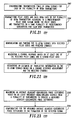
- FIG. 22 is a flow chart of one embodiment of steps of a method for implementing SC-OFDM reception in accordance with the present invention.
- the method for implementing synchronous coherent orthogonal frequency division multiplexing reception utilizing an OFDM receiver arranged to receive SC-OFDM signals includes the steps of:
- the steps of the method are typically implemented in one of: A) an application-specific integrated circuit; B) a digital signal processor; C) a processor; D) code; E) a combination of at least two of A-D.
- FIG. 23 is a flow chart of one embodiment of steps of a method for implementing efficient OFDM reception in accordance with the present invention.
- the method provides efficient orthogonal frequency division multiplexing reception upon receiving at least one orthogonal frequency division multiplexing signal, where the receiver uses at least frequency demultiplexed signals from a plurality of subcarriers to provide a detected signal.
- the method includes the steps of: A) measuring (2302) an average adjacent-subcarriers phase difference based on at least frequency demultiplexed signals from a plurality of subcarriers to provide a measured adjacent-subcarriers phase difference; and B) compensating (2304) for the measured average adjacent-subcarriers phase difference in the formation of the detected signal.
- the steps of the method are typically implemented in one of: A) an application-specific integrated circuit; B) a digital signal processor; C) a processor; D) code; E) a combination of at least two of A-D.
- FIG. 24 is a block diagram of one embodiment of an orthogonal frequency division multiplexing OFDM receiver for receiving at least one orthogonal frequency division multiplexing signal, frequency demultiplexing the signal into a plurality of demultiplexed signals from a plurality of subcarriers, and for detecting at least one symbol from the demultiplexed signals in accordance with the present invention.
- the OFDM receiver (2408) includes: A) an adjacent-subcarriers phase difference measurement unit (2402), coupled to receive the demultiplexed signals, for measuring an average adjacent-subcarriers phase difference, to provide a measured average adjacent-subcarriers phase difference; B) an adjacent-subcarriers phase difference compensation unit (2404), coupled to the adjacent-subcarriers phase difference measurement unit and the demultiplexed signals, for compensating the demultiplexed signals for the measured average adjacent-subcarriers phase difference to provide compensated signals; and C) detector (2406), coupled to the adjacent-subcarriers phase difference compensation unit, for detecting at least one symbol to provide at least one detected symbol, based on at least the compensated signals.
- FIG. 25 is a block diagram of one embodiment of an orthogonal frequency division multiplexing (OFDM) receiver (2502) for receiving at least one orthogonal frequency division multiplexing signal, frequency demultiplexing the signal into a plurality of demultiplexed signals from a plurality of subcarriers, and for detecting at least one symbol from the demultiplexed signals in accordance with the present invention.
- OFDM orthogonal frequency division multiplexing
- the OFDM receiver includes: A) an adjacent-subcarriers phase difference measurement unit (2504), coupled to receive the demultiplexed signals, for measuring an average adjacent-subcarriers phase difference to provide a measured average adjacent-subcarriers phase difference; and B) a detector with compensation unit (2506), coupled to the adjacent-subcarriers phase difference measurement unit (2504) and the demultiplexed signals, for providing at least one detected symbol based on at least the demultiplexed signals and the measured adjacent-subcarriers phase difference.
- FIG. 26 is a block diagram of one embodiment of a synchronous coherent orthogonal frequency division multiplexing, SC-OFDM, receiver for receiving at least one composite SC-OFDM signal, frequency demultiplexing the composite SC-OFDM signal into a plurality of composite SC-OFDM symbols from a plurality of subcarriers, and for detecting at least one symbol component from at least one composite SC-OFDM symbol in accordance with the present invention.
- SC-OFDM synchronous coherent orthogonal frequency division multiplexing
- the SC-OFDM receiver (2602) includes: A) an adjacent-subcarriers phase difference measurement unit (2604), coupled to receive the composite synchronous coherent orthogonal frequency division multiplexing symbols, for measuring an average adjacent-subcarriers phase difference, to provide a measured average adjacent-subcarriers phase difference; B) an adjacent-subcarriers phase difference compensation unit (2606), coupled to the adjacent-subcarriers phase difference measurement unit (2606) and the composite SC-OFDM symbols, for compensating the composite SC-OFDM symbols for the measured average adjacent-subcarriers phase difference to provide compensated composite SC-OFDM symbols; and C) a detector (2608), coupled to the adjacent-subcarriers phase difference compensation unit (2606), for detecting at least one symbol component of at least one composite SC-OFDM symbol to provide at least one detected symbol component based on at least the compensated composite SC-OFDM symbols.
- FIG. 27 is a block diagram of one embodiment of a synchronous coherent orthogonal frequency division multiplexing, SC-OFDM, receiver (2702) for receiving at least one composite SC-OFDM signal, frequency demultiplexing the composite SC-OFDM signal into a plurality of composite SC-OFDM symbols from a plurality of subcarriers, and for detecting at least one symbol component from at least one composite SC-OFDM symbol in accordance with the present invention.
- SC-OFDM synchronous coherent orthogonal frequency division multiplexing
- the SC-OFDM receiver (2702) includes: A) a multichannel adjacent-subcarriers phase difference measurement unit (2704), coupled to receive the composite SC-OFDM symbols, for measuring an average adjacent-subcarriers phase difference for a plurality of components of the composite SC-OFDM symbols, to provide a plurality of measured average adjacent-subcarriers phase differences; and B) a detector with multichannel adjacent-subcarriers phase difference compensation unit (2706), coupled to the multichannel adjacent-subcarriers phase difference measurement unit (2704) and the composite SC-OFDM symbols, for detecting at least one symbol component of at least one composite SC-OFDM symbol to provide at least one detected symbol component based on at least the compensated composite SC-OFDM symbols and the plurality of measured average adjacent-subcarriers phase differences.
Landscapes
- Engineering & Computer Science (AREA)
- Signal Processing (AREA)
- Computer Networks & Wireless Communication (AREA)
- Mobile Radio Communication Systems (AREA)
Applications Claiming Priority (2)
| Application Number | Priority Date | Filing Date | Title |
|---|---|---|---|
| US08/879,403 US5867478A (en) | 1997-06-20 | 1997-06-20 | Synchronous coherent orthogonal frequency division multiplexing system, method, software and device |
| EP98918637A EP0983654A4 (fr) | 1997-06-20 | 1998-04-21 | Systeme de multiplexage en frequence orthogonal, coherent, synchrone |
Related Parent Applications (1)
| Application Number | Title | Priority Date | Filing Date |
|---|---|---|---|
| EP98918637A Division EP0983654A4 (fr) | 1997-06-20 | 1998-04-21 | Systeme de multiplexage en frequence orthogonal, coherent, synchrone |
Publications (2)
| Publication Number | Publication Date |
|---|---|
| EP2028783A2 true EP2028783A2 (fr) | 2009-02-25 |
| EP2028783A3 EP2028783A3 (fr) | 2009-03-18 |
Family
ID=25374088
Family Applications (2)
| Application Number | Title | Priority Date | Filing Date |
|---|---|---|---|
| EP98918637A Ceased EP0983654A4 (fr) | 1997-06-20 | 1998-04-21 | Systeme de multiplexage en frequence orthogonal, coherent, synchrone |
| EP08020061A Withdrawn EP2028783A3 (fr) | 1997-06-20 | 1998-04-21 | Système de multiplexage de division de fréquence orthogonale cohérente synchrone |
Family Applications Before (1)
| Application Number | Title | Priority Date | Filing Date |
|---|---|---|---|
| EP98918637A Ceased EP0983654A4 (fr) | 1997-06-20 | 1998-04-21 | Systeme de multiplexage en frequence orthogonal, coherent, synchrone |
Country Status (3)
| Country | Link |
|---|---|
| US (1) | US5867478A (fr) |
| EP (2) | EP0983654A4 (fr) |
| WO (1) | WO1998059450A1 (fr) |
Cited By (2)
| Publication number | Priority date | Publication date | Assignee | Title |
|---|---|---|---|---|
| US8014311B2 (en) | 2009-06-08 | 2011-09-06 | Telefonaktiebolaget L M Ericsson (Publ) | Signal measurements based on sync signals |
| EP2520036A4 (fr) * | 2009-12-28 | 2017-06-21 | Telefonaktiebolaget LM Ericsson (publ) | Procédé et agencement d'étalonnage de temps de propagation pour système ofdm |
Families Citing this family (387)
| Publication number | Priority date | Publication date | Assignee | Title |
|---|---|---|---|---|
| US6005876A (en) * | 1996-03-08 | 1999-12-21 | At&T Corp | Method and apparatus for mobile data communication |
| US6115427A (en) | 1996-04-26 | 2000-09-05 | At&T Corp. | Method and apparatus for data transmission using multiple transmit antennas |
| CA2214934C (fr) * | 1996-09-24 | 2001-10-30 | At&T Corp. | Methode et appareil de communication mobile de donnees |
| FI102340B1 (fi) * | 1997-01-16 | 1998-11-13 | Nokia Telecommunications Oy | Tiedonsiirtomenetelmä ja radiojärjestelmä |
| US10917163B2 (en) | 2014-08-15 | 2021-02-09 | SEAKR Engineering, Inc. | Integrated mixed-signal RF transceiver with ADC, DAC, and DSP and high-bandwidth coherent recombination |
| US6333953B1 (en) * | 1997-07-21 | 2001-12-25 | Ericsson Inc. | System and methods for selecting an appropriate detection technique in a radiocommunication system |
| USRE43829E1 (en) * | 1997-09-04 | 2012-11-27 | Sony Deutchland GmbH | Transmission system for OFDM-signals with optimized synchronization |
| EP1713225B1 (fr) * | 1997-09-04 | 2008-09-24 | Sony Deutschland Gmbh | Système de transmission de signaux MFDO avec synchronisation optimisée |
| US6088408A (en) | 1998-11-06 | 2000-07-11 | At & T Corp. | Decoding for generalized orthogonal designs for space-time codes for wireless communication |
| KR100265735B1 (ko) * | 1997-11-25 | 2000-09-15 | 윤종용 | Fft윈도우위치복원과샘플링클럭제어가연동되는ofdm수신장치및그방법 |
| GB2332603B (en) * | 1997-12-22 | 2000-07-19 | Lsi Logic Corp | Improvements relating to multidirectional communication systems |
| US6064645A (en) * | 1997-12-22 | 2000-05-16 | Trw Inc. | Bulk filtering and demodulation of independent FDMA sources |
| EP2254300B1 (fr) * | 1998-01-06 | 2013-05-15 | Mosaid Technologies Incorporated | Système de modulation multiporteuse à débits de symboles variables |
| JP3724940B2 (ja) * | 1998-01-08 | 2005-12-07 | 株式会社東芝 | Ofdmダイバーシチ受信装置 |
| JP3718337B2 (ja) * | 1998-01-08 | 2005-11-24 | 株式会社東芝 | 適応可変指向性アンテナ |
| JP3737264B2 (ja) * | 1998-01-14 | 2006-01-18 | 株式会社東芝 | ダイバーシチ受信装置 |
| US20030138058A1 (en) * | 1998-02-06 | 2003-07-24 | Dakshi Agrawal | Diversity coded OFDM for high data-rate communication |
| US6618454B1 (en) * | 1998-02-06 | 2003-09-09 | At&T Corp. | Diversity coded OFDM for high data-rate communication |
| US6148007A (en) * | 1998-03-27 | 2000-11-14 | Usa Digital Radio Partners, L.P. | Method for data transmission in a digital audio broadcasting system |
| US6529488B1 (en) * | 1998-08-18 | 2003-03-04 | Motorola, Inc. | Multiple frequency allocation radio frequency device and method |
| ES2183651T3 (es) * | 1998-10-27 | 2003-03-16 | Siemens Ag | Procedimiento de asignacion de canal y dispositivo para conjuntos de informacion codificados y combinados. |
| US6400780B1 (en) * | 1998-11-06 | 2002-06-04 | Lucent Technologies Inc. | Space-time diversity for wireless systems |
| US7020071B2 (en) * | 1998-11-25 | 2006-03-28 | Lucent Technologies Inc. | Methods and apparatus for wireless communication using orthogonal frequency division multiplexing |
| US6473393B1 (en) * | 1998-12-18 | 2002-10-29 | At&T Corp. | Channel estimation for OFDM systems with transmitter diversity |
| US6728302B1 (en) * | 1999-02-12 | 2004-04-27 | Texas Instruments Incorporated | STTD encoding for PCCPCH |
| JP3085944B2 (ja) * | 1999-02-15 | 2000-09-11 | 三菱電機株式会社 | Ofdm通信システム用受信装置 |
| FR2790343B1 (fr) * | 1999-02-26 | 2001-06-01 | Thomson Csf | Systeme pour l'estimation du gain complexe d'un canal de transmission |
| US6295326B1 (en) | 1999-03-08 | 2001-09-25 | Bandspeed, Inc. | Kalman filter based equalization for digital multicarrier communications systems |
| US6473418B1 (en) * | 1999-03-11 | 2002-10-29 | Flarion Technologies, Inc. | Orthogonal frequency division multiplexing based spread spectrum multiple access |
| CA2299568A1 (fr) * | 1999-03-11 | 2000-09-11 | Lucent Technologies Inc. | Systeme d'acces multiple a spectre etale, a multiplexage par repartition orthogonale de la frequence et a antenne directionnelle |
| US6711120B1 (en) * | 1999-03-11 | 2004-03-23 | Flarion Technologies, Inc. | Orthogonal frequency division multiplexing based spread spectrum multiple access |
| FR2792138B1 (fr) * | 1999-04-06 | 2001-06-01 | Telediffusion Fse | Reconstitution de messages repartis frequentiellement et temporellement dans un reseau de collecte de donnees |
| US7952511B1 (en) | 1999-04-07 | 2011-05-31 | Geer James L | Method and apparatus for the detection of objects using electromagnetic wave attenuation patterns |
| US6952394B1 (en) | 1999-05-25 | 2005-10-04 | Samsung Electronics Co., Ltd. | Method for transmitting and receiving orthogonal frequency division multiplexing signal and apparatus therefor |
| US6807147B1 (en) * | 1999-06-23 | 2004-10-19 | At&T Wireless Services, Inc. | Methods and apparatus for use in obtaining frame synchronization in an OFDM communication system |
| KR100294070B1 (ko) | 1999-06-23 | 2001-06-15 | 박태진 | 이중주파수도약 통신 시스템 및 제어방법 |
| US7324495B1 (en) * | 1999-06-23 | 2008-01-29 | Clearwire Corporation | System and method for broadcasting timing information to remote units in a wireless multiple access network |
| CN1819537A (zh) * | 1999-10-22 | 2006-08-16 | 耐克斯特奈特无线公司 | 利用具有内部天线的cpe的固定ofdm无线大城市区通信网 |
| US6631143B1 (en) * | 1999-11-12 | 2003-10-07 | Lucent Technologies Inc. | Methods and apparatus for frame synchronization in a digital audio broadcasting system |
| US7324437B1 (en) | 1999-11-27 | 2008-01-29 | Deutsche Telekom Ag | Method for co-channel interference cancellation in a multicarrier communication system |
| US6298035B1 (en) * | 1999-12-21 | 2001-10-02 | Nokia Networks Oy | Estimation of two propagation channels in OFDM |
| AU2757701A (en) | 1999-12-30 | 2001-07-16 | Bandspeed, Inc. | Approach for processing data received from a communications channel in finite precision arithmetic applications |
| US7512409B1 (en) * | 2000-01-13 | 2009-03-31 | Zion Hadad Communications Ltd. | Cellular network system |
| JP3581072B2 (ja) * | 2000-01-24 | 2004-10-27 | 株式会社エヌ・ティ・ティ・ドコモ | チャネル構成方法及びその方法を利用する基地局 |
| US6922388B1 (en) * | 2000-02-11 | 2005-07-26 | Lucent Technologies Inc. | Signal construction, detection and estimation for uplink timing synchronization and access control in a multi-access wireless communication system |
| US6952454B1 (en) * | 2000-03-22 | 2005-10-04 | Qualcomm, Incorporated | Multiplexing of real time services and non-real time services for OFDM systems |
| CN1108071C (zh) * | 2000-04-11 | 2003-05-07 | 信息产业部电信科学技术研究院 | 码分多址移动通信系统中终端设备端的一种信号处理方法 |
| EP1146708A1 (fr) * | 2000-04-12 | 2001-10-17 | Rolf Matzner | Système de transmission à modulation multiporteuses utilisant des canaux MIMO |
| EP1148659B1 (fr) * | 2000-04-18 | 2005-07-27 | Sony International (Europe) GmbH | Transmission OFDM en diversité |
| US6954481B1 (en) * | 2000-04-18 | 2005-10-11 | Flarion Technologies, Inc. | Pilot use in orthogonal frequency division multiplexing based spread spectrum multiple access systems |
| US6961364B1 (en) * | 2000-04-18 | 2005-11-01 | Flarion Technologies, Inc. | Base station identification in orthogonal frequency division multiplexing based spread spectrum multiple access systems |
| AU2001271297A1 (en) * | 2000-06-12 | 2001-12-24 | Larry W. Fullerton | A method for specifying non-temporal pulse characteristics |
| US8363744B2 (en) * | 2001-06-10 | 2013-01-29 | Aloft Media, Llc | Method and system for robust, secure, and high-efficiency voice and packet transmission over ad-hoc, mesh, and MIMO communication networks |
| JP2002009733A (ja) * | 2000-06-27 | 2002-01-11 | Hitachi Kokusai Electric Inc | 直交周波数分割多重変調方式の伝送装置 |
| EP1170897B1 (fr) * | 2000-07-05 | 2020-01-15 | Wi-Fi One Technologies International Limited | Schéma de symboles pilotes pour un arrangement en STTD dans un système OFDM |
| EP1170917B1 (fr) * | 2000-07-06 | 2006-10-04 | Sony Deutschland GmbH | Procédé et dispositif pour fournir la liaison montante d'un système OFDM utilisant un entrelacement temps-fréquence |
| EP1176750A1 (fr) * | 2000-07-25 | 2002-01-30 | Telefonaktiebolaget L M Ericsson (Publ) | Détermination de la qualité de liaison d'un canal de transmission dans un système de transmission de OFDM |
| US6721267B2 (en) * | 2000-08-01 | 2004-04-13 | Motorola, Inc. | Time and bandwidth scalable slot format for mobile data system |
| US6424678B1 (en) * | 2000-08-01 | 2002-07-23 | Motorola, Inc. | Scalable pattern methodology for multi-carrier communication systems |
| DE60028200T2 (de) * | 2000-08-01 | 2007-03-15 | Sony Deutschland Gmbh | Vorrichtung und Verfahren zur Kanalschätzung für OFDM-System |
| DE60035683T2 (de) * | 2000-08-01 | 2008-06-26 | Sony Deutschland Gmbh | Frequenzwiederverwendungsschema für OFDM-Systeme |
| DE10039902B4 (de) * | 2000-08-16 | 2011-04-28 | Rohde & Schwarz Gmbh & Co. Kg | Verfahren zur Frequenz- und Zeit-Synchronisation eines Empfängers |
| EP1182817B1 (fr) * | 2000-08-24 | 2007-12-26 | Sony Deutschland GmbH | Dispositif de communication pour l'émission et la réception de signaux OFDM dans un système de communication sans fil |
| US6937592B1 (en) * | 2000-09-01 | 2005-08-30 | Intel Corporation | Wireless communications system that supports multiple modes of operation |
| US7295509B2 (en) * | 2000-09-13 | 2007-11-13 | Qualcomm, Incorporated | Signaling method in an OFDM multiple access system |
| US9130810B2 (en) * | 2000-09-13 | 2015-09-08 | Qualcomm Incorporated | OFDM communications methods and apparatus |
| US6985433B1 (en) * | 2000-09-15 | 2006-01-10 | Flarion Technologies, Inc. | Methods and apparatus for determining minimum cyclicprefix durations |
| US7031371B1 (en) | 2000-09-25 | 2006-04-18 | Lakkis Ismail A | CDMA/TDMA communication method and apparatus for wireless communication using cyclic spreading codes |
| US7339955B2 (en) * | 2000-09-25 | 2008-03-04 | Pulse-Link, Inc. | TDMA communication method and apparatus using cyclic spreading codes |
| US6721569B1 (en) * | 2000-09-29 | 2004-04-13 | Nortel Networks Limited | Dynamic sub-carrier assignment in OFDM systems |
| US6870808B1 (en) | 2000-10-18 | 2005-03-22 | Adaptix, Inc. | Channel allocation in broadband orthogonal frequency-division multiple-access/space-division multiple-access networks |
| US6654408B1 (en) | 2000-10-27 | 2003-11-25 | Wisconsin Alumni Research Foundation | Method and system for multi-carrier multiple access reception in the presence of imperfections |
| US6567387B1 (en) | 2000-11-07 | 2003-05-20 | Intel Corporation | System and method for data transmission from multiple wireless base transceiver stations to a subscriber unit |
| SE0004403L (sv) * | 2000-11-29 | 2002-05-30 | Ericsson Telefon Ab L M | Metoder och anordningar i ett telekommunikationssystem |
| US6804223B2 (en) * | 2000-11-30 | 2004-10-12 | Ipr Licensing, Inc. | Reverse link pilot integrated with block codes |
| US6947748B2 (en) | 2000-12-15 | 2005-09-20 | Adaptix, Inc. | OFDMA with adaptive subcarrier-cluster configuration and selective loading |
| WO2002049306A2 (fr) * | 2000-12-15 | 2002-06-20 | Broadstorm Telecommunications, Inc. | Communications a ondes porteuses multiples avec attribution d'ondes porteuses basee sur des groupes |
| GB2370452B (en) * | 2000-12-19 | 2004-10-20 | Inmarsat Ltd | Communication method and apparatus |
| US7054375B2 (en) * | 2000-12-22 | 2006-05-30 | Nokia Corporation | Method and apparatus for error reduction in an orthogonal modulation system |
| JP3857528B2 (ja) * | 2001-01-12 | 2006-12-13 | 富士通株式会社 | 同期検出装置 |
| US6529559B2 (en) * | 2001-01-12 | 2003-03-04 | Comsys Communication & Signal Processing Ltd. | Reduced soft output information packet selection |
| US7002934B2 (en) | 2001-01-22 | 2006-02-21 | Unique Broadband Systems, Inc. | OFDM multiple upstream receiver network |
| US6996199B2 (en) | 2001-01-25 | 2006-02-07 | Bandspeed, Inc. | Approach for processing data received from a communications channel to reduce noise power and optimize impulse response length to reduce inter-symbol interference and inter-channel interference |
| US7751469B2 (en) * | 2001-02-20 | 2010-07-06 | Massachusetts Institute Of Technology | Correlation shaping matched filter receiver |
| US7636403B2 (en) * | 2001-02-20 | 2009-12-22 | Massachusetts Institute Of Technology | Correlation shaping multi-signature receiver |
| US20020118783A1 (en) * | 2001-02-26 | 2002-08-29 | Peter Cripps | Smart antenna based spectrum multiplexing using a pilot signal |
| WO2002073937A2 (fr) | 2001-03-14 | 2002-09-19 | Mercury Computer Systems, Inc. | Systemes et procedes de communications sans fil pour le traitement de formes d'onde a etalement du spectre et de formes d'onde long code |
| US7376175B2 (en) * | 2001-03-14 | 2008-05-20 | Mercury Computer Systems, Inc. | Wireless communications systems and methods for cache enabled multiple processor based multiple user detection |
| DE10112773B4 (de) * | 2001-03-16 | 2012-09-20 | Rohde & Schwarz Gmbh & Co Kg | Verfahren zur Frequenz- und Zeit-Synchronisation eines OFDM-Empfängers |
| US20020136287A1 (en) * | 2001-03-20 | 2002-09-26 | Heath Robert W. | Method, system and apparatus for displaying the quality of data transmissions in a wireless communication system |
| US6961545B2 (en) * | 2001-04-09 | 2005-11-01 | Atheros Communications, Inc. | Method and system for providing antenna diversity |
| US7706458B2 (en) * | 2001-04-24 | 2010-04-27 | Mody Apurva N | Time and frequency synchronization in Multi-Input, Multi-Output (MIMO) systems |
| US7088782B2 (en) * | 2001-04-24 | 2006-08-08 | Georgia Tech Research Corporation | Time and frequency synchronization in multi-input, multi-output (MIMO) systems |
| US7310304B2 (en) * | 2001-04-24 | 2007-12-18 | Bae Systems Information And Electronic Systems Integration Inc. | Estimating channel parameters in multi-input, multi-output (MIMO) systems |
| US7145959B2 (en) * | 2001-04-25 | 2006-12-05 | Magnolia Broadband Inc. | Smart antenna based spectrum multiplexing using existing pilot signals for orthogonal frequency division multiplexing (OFDM) modulations |
| WO2002091651A2 (fr) * | 2001-05-10 | 2002-11-14 | Sasken | Echange rapide en cours d'initialisation dans les systemes de communications a porteuses multiples |
| US6810236B2 (en) * | 2001-05-14 | 2004-10-26 | Interdigital Technology Corporation | Dynamic channel quality measurement procedure for adaptive modulation and coding techniques |
| US7012966B2 (en) * | 2001-05-21 | 2006-03-14 | At&T Corp. | Channel estimation for wireless systems with multiple transmit antennas |
| US7103115B2 (en) | 2001-05-21 | 2006-09-05 | At&T Corp. | Optimum training sequences for wireless systems |
| US8249187B2 (en) | 2002-05-09 | 2012-08-21 | Google Inc. | System, method and apparatus for mobile transmit diversity using symmetric phase difference |
| DE60230981D1 (de) * | 2001-05-31 | 2009-03-12 | Magnolia Broadband Inc | Kommunikationseinrichtung mit intelligenter antenne, die ein qualitätsanzeigesignal verwendet |
| WO2003001696A2 (fr) * | 2001-06-21 | 2003-01-03 | Flarion Technologies, Inc. | Procede d'attribution de tonalites pour les sequences de saut de tonalites |
| JP3660278B2 (ja) * | 2001-07-13 | 2005-06-15 | 松下電器産業株式会社 | 基地局装置、移動局装置、無線通信システム及び無線通信方法 |
| US20030026252A1 (en) * | 2001-07-31 | 2003-02-06 | Thunquest Gary L. | Data packet structure for directly addressed multicast protocol |
| US7962162B2 (en) * | 2001-08-07 | 2011-06-14 | At&T Intellectual Property Ii, L.P. | Simulcasting OFDM system having mobile station location identification |
| US7388930B1 (en) | 2001-08-10 | 2008-06-17 | Bandspeed, Inc. | Method and apparatus for removing crosstalk and other interference in communications systems |
| EP2538723B1 (fr) * | 2001-08-14 | 2019-07-03 | Qualcomm Incorporated | Procédé et appareil pour la connectivité par réseau sans fil |
| US8116260B1 (en) * | 2001-08-22 | 2012-02-14 | At&T Intellectual Property Ii, L.P. | Simulcasting MIMO communication system |
| JP4171261B2 (ja) | 2001-08-27 | 2008-10-22 | 松下電器産業株式会社 | 無線通信装置及び無線通信方法 |
| US7149254B2 (en) * | 2001-09-06 | 2006-12-12 | Intel Corporation | Transmit signal preprocessing based on transmit antennae correlations for multiple antennae systems |
| FR2829642B1 (fr) * | 2001-09-12 | 2004-01-16 | Eads Defence & Security Ntwk | Signal multiporteuses, procede de poursuite d'un canal de transmission a partir d'un tel signal et dispositif pour sa mise en oeuvre |
| US20030067890A1 (en) * | 2001-10-10 | 2003-04-10 | Sandesh Goel | System and method for providing automatic re-transmission of wirelessly transmitted information |
| US7061854B2 (en) * | 2001-10-15 | 2006-06-13 | Nortel Networks Limited | Efficient OFDM communications with interference immunity |
| US7548506B2 (en) * | 2001-10-17 | 2009-06-16 | Nortel Networks Limited | System access and synchronization methods for MIMO OFDM communications systems and physical layer packet and preamble design |
| US7248559B2 (en) | 2001-10-17 | 2007-07-24 | Nortel Networks Limited | Scattered pilot pattern and channel estimation method for MIMO-OFDM systems |
| JP3997890B2 (ja) | 2001-11-13 | 2007-10-24 | 松下電器産業株式会社 | 送信方法及び送信装置 |
| US7336719B2 (en) | 2001-11-28 | 2008-02-26 | Intel Corporation | System and method for transmit diversity base upon transmission channel delay spread |
| US20050053121A1 (en) * | 2001-12-06 | 2005-03-10 | Ismail Lakkis | Ultra-wideband communication apparatus and methods |
| US7289494B2 (en) * | 2001-12-06 | 2007-10-30 | Pulse-Link, Inc. | Systems and methods for wireless communication over a wide bandwidth channel using a plurality of sub-channels |
| US20050058180A1 (en) * | 2001-12-06 | 2005-03-17 | Ismail Lakkis | Ultra-wideband communication apparatus and methods |
| US7406647B2 (en) | 2001-12-06 | 2008-07-29 | Pulse-Link, Inc. | Systems and methods for forward error correction in a wireless communication network |
| US7317756B2 (en) * | 2001-12-06 | 2008-01-08 | Pulse-Link, Inc. | Ultra-wideband communication apparatus and methods |
| US7403576B2 (en) | 2001-12-06 | 2008-07-22 | Pulse-Link, Inc. | Systems and methods for receiving data in a wireless communication network |
| US7391815B2 (en) * | 2001-12-06 | 2008-06-24 | Pulse-Link, Inc. | Systems and methods to recover bandwidth in a communication system |
| US20050152483A1 (en) * | 2001-12-06 | 2005-07-14 | Ismail Lakkis | Systems and methods for implementing path diversity in a wireless communication network |
| US20050201473A1 (en) * | 2001-12-06 | 2005-09-15 | Ismail Lakkis | Systems and methods for receiving data in a wireless communication network |
| US8045935B2 (en) * | 2001-12-06 | 2011-10-25 | Pulse-Link, Inc. | High data rate transmitter and receiver |
| US7349439B2 (en) * | 2001-12-06 | 2008-03-25 | Pulse-Link, Inc. | Ultra-wideband communication systems and methods |
| US7483483B2 (en) * | 2001-12-06 | 2009-01-27 | Pulse-Link, Inc. | Ultra-wideband communication apparatus and methods |
| US7257156B2 (en) * | 2001-12-06 | 2007-08-14 | Pulse˜Link, Inc. | Systems and methods for equalization of received signals in a wireless communication network |
| US7450637B2 (en) * | 2001-12-06 | 2008-11-11 | Pulse-Link, Inc. | Ultra-wideband communication apparatus and methods |
| EP1335552B1 (fr) * | 2002-02-07 | 2007-01-10 | Mitsubishi Electric Information Technology Centre Europe B.V. | Estimation de canal et de retard dans des systèmes à porteuses multiples |
| FI20020387A0 (fi) * | 2002-02-28 | 2002-02-28 | Nokia Corp | Menetelmä ja järjestelmä monikantoaaltosignaalin vastaanottamiseksi |
| GB2386519B (en) * | 2002-03-12 | 2004-05-26 | Toshiba Res Europ Ltd | Adaptive Multicarrier Communication |
| US7092452B2 (en) * | 2002-03-25 | 2006-08-15 | Bae Systems Information And Electronic Systems Integration Inc | Co-channel interference receiver |
| US7012978B2 (en) * | 2002-03-26 | 2006-03-14 | Intel Corporation | Robust multiple chain receiver |
| US20030235252A1 (en) * | 2002-06-19 | 2003-12-25 | Jose Tellado | Method and system of biasing a timing phase estimate of data segments of a received signal |
| JP4490265B2 (ja) | 2002-07-24 | 2010-06-23 | ビーエイイー・システムズ・インフォメーション・アンド・エレクトロニック・システムズ・インテグレイション・インコーポレーテッド | 同一チャネル干渉受信機 |
| US8213994B2 (en) * | 2002-08-07 | 2012-07-03 | Interdigital Technology Corporation | Mobile communications system and method for providing common channel coverage using beamforming antennas |
| US8861466B2 (en) | 2002-08-07 | 2014-10-14 | Interdigital Technology Corporation | Mobile communication system and method for providing common channel coverage using beamforming antennas |
| US7388845B2 (en) * | 2002-08-26 | 2008-06-17 | Qualcomm Incorporated | Multiple access wireless communications system using a multisector configuration |
| US7366200B2 (en) * | 2002-08-26 | 2008-04-29 | Qualcomm Incorporated | Beacon signaling in a wireless system |
| US6985498B2 (en) * | 2002-08-26 | 2006-01-10 | Flarion Technologies, Inc. | Beacon signaling in a wireless system |
| US7133354B2 (en) * | 2002-08-26 | 2006-11-07 | Qualcomm Incorporated | Synchronization techniques for a wireless system |
| US8194770B2 (en) * | 2002-08-27 | 2012-06-05 | Qualcomm Incorporated | Coded MIMO systems with selective channel inversion applied per eigenmode |
| US20040047368A1 (en) * | 2002-08-28 | 2004-03-11 | Xu Jin Biao | Frame synchronization for OFDM systems |
| US20040052228A1 (en) * | 2002-09-16 | 2004-03-18 | Jose Tellado | Method and system of frequency and time synchronization of a transceiver to signals received by the transceiver |
| TW200729983A (en) * | 2002-09-27 | 2007-08-01 | Interdigital Tech Corp | Mobile communications system and method for providing mobile unit handover in wireless communication systems that employ beamforming antennas |
| US7889819B2 (en) * | 2002-10-04 | 2011-02-15 | Apurva Mody | Methods and systems for sampling frequency offset detection, correction and control for MIMO OFDM systems |
| US8170513B2 (en) * | 2002-10-25 | 2012-05-01 | Qualcomm Incorporated | Data detection and demodulation for wireless communication systems |
| US8169944B2 (en) | 2002-10-25 | 2012-05-01 | Qualcomm Incorporated | Random access for wireless multiple-access communication systems |
| US8134976B2 (en) * | 2002-10-25 | 2012-03-13 | Qualcomm Incorporated | Channel calibration for a time division duplexed communication system |
| US8320301B2 (en) | 2002-10-25 | 2012-11-27 | Qualcomm Incorporated | MIMO WLAN system |
| US20040081131A1 (en) | 2002-10-25 | 2004-04-29 | Walton Jay Rod | OFDM communication system with multiple OFDM symbol sizes |
| US8218609B2 (en) * | 2002-10-25 | 2012-07-10 | Qualcomm Incorporated | Closed-loop rate control for a multi-channel communication system |
| US7324429B2 (en) | 2002-10-25 | 2008-01-29 | Qualcomm, Incorporated | Multi-mode terminal in a wireless MIMO system |
| US8570988B2 (en) * | 2002-10-25 | 2013-10-29 | Qualcomm Incorporated | Channel calibration for a time division duplexed communication system |
| US7002900B2 (en) * | 2002-10-25 | 2006-02-21 | Qualcomm Incorporated | Transmit diversity processing for a multi-antenna communication system |
| US7986742B2 (en) * | 2002-10-25 | 2011-07-26 | Qualcomm Incorporated | Pilots for MIMO communication system |
| US8208364B2 (en) | 2002-10-25 | 2012-06-26 | Qualcomm Incorporated | MIMO system with multiple spatial multiplexing modes |
| US7042857B2 (en) * | 2002-10-29 | 2006-05-09 | Qualcom, Incorporated | Uplink pilot and signaling transmission in wireless communication systems |
| US7016651B1 (en) | 2002-12-17 | 2006-03-21 | Marvell International Ltd. | Apparatus and method for measuring signal quality of a wireless communications link |
| US7280467B2 (en) * | 2003-01-07 | 2007-10-09 | Qualcomm Incorporated | Pilot transmission schemes for wireless multi-carrier communication systems |
| US7738437B2 (en) * | 2003-01-21 | 2010-06-15 | Nortel Networks Limited | Physical layer structures and initial access schemes in an unsynchronized communication network |
| FR2851384B1 (fr) * | 2003-02-17 | 2009-12-18 | Wavecom | Procede de transmission de donnees radio, signal, systeme et dispositifs correspondant. |
| WO2004075502A2 (fr) * | 2003-02-19 | 2004-09-02 | Matsushita Electric Industrial Co. Ltd. | Appareil et procede de reception pour transmission numerique a porteuses multiples |
| US8811348B2 (en) * | 2003-02-24 | 2014-08-19 | Qualcomm Incorporated | Methods and apparatus for generating, communicating, and/or using information relating to self-noise |
| AU2004214806A1 (en) * | 2003-02-24 | 2004-09-10 | Qualcomm Incorporated | Pilot signals for use in multi-sector cells |
| UA94018C2 (ru) * | 2003-02-24 | 2011-04-11 | Квелком Инкорпорейтед | Пилот-сигналы для использования в многосекторных сотах |
| US9661519B2 (en) * | 2003-02-24 | 2017-05-23 | Qualcomm Incorporated | Efficient reporting of information in a wireless communication system |
| US7218948B2 (en) * | 2003-02-24 | 2007-05-15 | Qualcomm Incorporated | Method of transmitting pilot tones in a multi-sector cell, including null pilot tones, for generating channel quality indicators |
| US9544860B2 (en) * | 2003-02-24 | 2017-01-10 | Qualcomm Incorporated | Pilot signals for use in multi-sector cells |
| US7095790B2 (en) * | 2003-02-25 | 2006-08-22 | Qualcomm, Incorporated | Transmission schemes for multi-antenna communication systems utilizing multi-carrier modulation |
| US7221722B2 (en) * | 2003-02-27 | 2007-05-22 | Motorola, Inc. | Method and apparatus for reducing interference within a communication system |
| US7688786B2 (en) * | 2003-03-17 | 2010-03-30 | Qualcomm Incorporated | Avoiding data loss and reducing registration overhead in packet networks |
| US7933255B2 (en) | 2003-04-07 | 2011-04-26 | Bellow Bellows Llc | Multi-antenna wireless data processing system |
| US7646744B2 (en) | 2003-04-07 | 2010-01-12 | Shaolin Li | Method of operating multi-antenna wireless data processing system |
| US7512083B2 (en) | 2003-04-07 | 2009-03-31 | Shaolin Li | Single chip multi-antenna wireless data processor |
| US7389096B2 (en) | 2003-04-07 | 2008-06-17 | Bellow Bellows Llc | Monitoring system using multi-antenna transceivers |
| US8014374B2 (en) | 2003-04-07 | 2011-09-06 | Bellow Bellows Llc | System and method for achieving timing compatibility with multi-antenna wireless data protocols |
| FR2854020B1 (fr) * | 2003-04-17 | 2005-09-09 | Wavecom | Procede de transmission de donnees radio mettant en oeuvre plusieurs motifs de pilotes distincts, procede de reception, systeme, mobile et station de base correspondants |
| FR2854009B1 (fr) * | 2003-04-17 | 2007-05-25 | Wavecom | Signal multiporteuse concu pour reduire les interferences cellulaires au sein d'un reseau de radiocommunication, procede de construction, procede de reception, recepteur et emetteur correspondants |
| US7177297B2 (en) * | 2003-05-12 | 2007-02-13 | Qualcomm Incorporated | Fast frequency hopping with a code division multiplexed pilot in an OFDMA system |
| US8064528B2 (en) | 2003-05-21 | 2011-11-22 | Regents Of The University Of Minnesota | Estimating frequency-offsets and multi-antenna channels in MIMO OFDM systems |
| US7418040B2 (en) * | 2003-05-30 | 2008-08-26 | Motorola, Inc. | Method and apparatus for determining a timing offset for processing a multi-carrier signal |
| US6999467B2 (en) * | 2003-07-28 | 2006-02-14 | Motorola, Inc. | Method and apparatus for transmission and reception within an OFDM communication system |
| US7502426B2 (en) * | 2003-09-09 | 2009-03-10 | Interdigital Technology Corporation | Method for estimating signal magnitude, noise power, and signal-to-noise ratio of received signals |
| KR100909434B1 (ko) * | 2003-09-22 | 2009-07-28 | 노키아 코포레이션 | 다중 반송파 송신을 수신하는 방법, 시스템 및 수신기 |
| KR100950668B1 (ko) * | 2003-09-30 | 2010-04-02 | 삼성전자주식회사 | 직교 주파수 분할 다중 접속 방식을 사용하는 통신 시스템에서 업링크 파일럿 신호 송수신 장치 및 방법 |
| US7242722B2 (en) * | 2003-10-17 | 2007-07-10 | Motorola, Inc. | Method and apparatus for transmission and reception within an OFDM communication system |
| US7092353B2 (en) * | 2003-10-17 | 2006-08-15 | Qualcomm Incorporated | Carrier search methods and apparatus |
| KR100594597B1 (ko) * | 2003-10-24 | 2006-06-30 | 한국전자통신연구원 | 이동통신시스템에서의 하향링크 신호 구성 방법 및 그장치와, 이를 이용한 동기화 및 셀 탐색 방법과 그 장치 |
| US9473269B2 (en) | 2003-12-01 | 2016-10-18 | Qualcomm Incorporated | Method and apparatus for providing an efficient control channel structure in a wireless communication system |
| EP1542488A1 (fr) | 2003-12-12 | 2005-06-15 | Telefonaktiebolaget LM Ericsson (publ) | Procédé et appareil d'affectation d'un signal pilote adapté à les caractéristique du canal |
| KR100560386B1 (ko) * | 2003-12-17 | 2006-03-13 | 한국전자통신연구원 | 무선 통신 시스템의 상향 링크에서 코히어런트 검출을위한 직교주파수 분할 다중 접속 방식의 송수신 장치 및그 방법 |
| JP4777907B2 (ja) * | 2004-01-20 | 2011-09-21 | クゥアルコム・インコーポレイテッド | 同期型ブロードキャスト/マルチキャスト通信 |
| US7339999B2 (en) * | 2004-01-21 | 2008-03-04 | Qualcomm Incorporated | Pilot transmission and channel estimation for an OFDM system with excess delay spread |
| US7272359B2 (en) | 2004-01-26 | 2007-09-18 | Magnolia Broadband Inc. | Communicating signals according to a quality indicator using multiple antenna elements |
| US20050163194A1 (en) * | 2004-01-28 | 2005-07-28 | Qualcomm Incorporated | Interference estimation in a wireless communication system |
| US8553822B2 (en) | 2004-01-28 | 2013-10-08 | Qualcomm Incorporated | Time filtering for excess delay mitigation in OFDM systems |
| US8009660B2 (en) * | 2004-01-29 | 2011-08-30 | Neocific, Inc. | Methods and apparatus using cell-specific and common pilot subcarriers in multi-carrier, multi-cell wireless communication networks |
| EP1712019B1 (fr) | 2004-01-29 | 2014-01-15 | Neocific, Inc. | Procedes et appareil de superpositon de signaux multi-porteuses et a spectre etale a sequence directe dans un systeme de transmission sans fil a bande large |
| CN1943152B (zh) | 2004-02-13 | 2011-07-27 | 桥扬科技有限公司 | 用于具有自适应发射和反馈的多载波通信系统的方法和设备 |
| CN103516459B (zh) * | 2004-03-15 | 2016-09-21 | 苹果公司 | 用于具有四根发射天线的ofdm系统的导频设计 |
| KR20050099905A (ko) * | 2004-04-12 | 2005-10-17 | 삼성전자주식회사 | 직교주파수분할 다중접속 시스템에서 고속 주파수 도약을위한 송수신 장치 |
| EP1589776A1 (fr) * | 2004-04-19 | 2005-10-26 | Telefonaktiebolaget LM Ericsson (publ) | Attribution dynamique de ressources radio |
| US8014264B2 (en) * | 2004-05-01 | 2011-09-06 | Neocific, Inc. | Methods and apparatus for communication with time-division duplexing |
| US7532565B2 (en) * | 2004-05-07 | 2009-05-12 | Texas Instruments Incorporated | Mapping data tones onto guard tones for a multi-band OFDM system |
| US20050265219A1 (en) * | 2004-05-11 | 2005-12-01 | Texas Instruments Incorporated | Orthogonal frequency division multiplex (OFDM) packet detect unit, method of detecting an OFDM packet and OFDM receiver employing the same |
| US8085831B2 (en) | 2004-05-17 | 2011-12-27 | Qualcomm Incorporated | Interference control via selective blanking/attenuation of interfering transmissions |
| US7920884B2 (en) * | 2004-06-04 | 2011-04-05 | Qualcomm Incorporated | Frame structures for a wireless communication system with multiple radio technologies |
| US9137822B2 (en) | 2004-07-21 | 2015-09-15 | Qualcomm Incorporated | Efficient signaling over access channel |
| US9148256B2 (en) * | 2004-07-21 | 2015-09-29 | Qualcomm Incorporated | Performance based rank prediction for MIMO design |
| US8891349B2 (en) | 2004-07-23 | 2014-11-18 | Qualcomm Incorporated | Method of optimizing portions of a frame |
| EP1635592B1 (fr) * | 2004-09-13 | 2007-05-23 | Alcatel Lucent | Esimation de la qualité de transmission dans un réseau de communication sans fil |
| US7924935B2 (en) * | 2004-09-30 | 2011-04-12 | Nortel Networks Limited | Channel sounding in OFDMA system |
| US7715845B2 (en) * | 2004-10-14 | 2010-05-11 | Qualcomm Incorporated | Tone hopping methods and apparatus |
| US7379446B2 (en) * | 2004-10-14 | 2008-05-27 | Qualcomm Incorporated | Enhanced beacon signaling method and apparatus |
| US8503938B2 (en) * | 2004-10-14 | 2013-08-06 | Qualcomm Incorporated | Methods and apparatus for determining, communicating and using information including loading factors which can be used for interference control purposes |
| KR100911087B1 (ko) * | 2004-10-14 | 2009-08-06 | 콸콤 인코포레이티드 | 간섭 제어 목적으로 사용될 수 있는 정보를 결정, 통신, 및사용하기 위한 방법 및 장치 |
| US7573851B2 (en) | 2004-12-07 | 2009-08-11 | Adaptix, Inc. | Method and system for switching antenna and channel assignments in broadband wireless networks |
| US8009551B2 (en) * | 2004-12-22 | 2011-08-30 | Qualcomm Incorporated | Initial pilot frequency selection |
| US7453849B2 (en) * | 2004-12-22 | 2008-11-18 | Qualcomm Incorporated | Method of implicit deassignment of resources |
| US8831115B2 (en) * | 2004-12-22 | 2014-09-09 | Qualcomm Incorporated | MC-CDMA multiplexing in an orthogonal uplink |
| US8238923B2 (en) * | 2004-12-22 | 2012-08-07 | Qualcomm Incorporated | Method of using shared resources in a communication system |
| US20070066232A1 (en) * | 2005-09-22 | 2007-03-22 | Black Peter J | Pilot grouping and route protocols in multi-carrier communication systems |
| US8150408B2 (en) * | 2005-03-08 | 2012-04-03 | Qualcomm Incorporated | Pilot grouping and set management in multi-carrier communication systems |
| US20060203794A1 (en) * | 2005-03-10 | 2006-09-14 | Qualcomm Incorporated | Systems and methods for beamforming in multi-input multi-output communication systems |
| US9246560B2 (en) | 2005-03-10 | 2016-01-26 | Qualcomm Incorporated | Systems and methods for beamforming and rate control in a multi-input multi-output communication systems |
| US9154211B2 (en) * | 2005-03-11 | 2015-10-06 | Qualcomm Incorporated | Systems and methods for beamforming feedback in multi antenna communication systems |
| US8446892B2 (en) * | 2005-03-16 | 2013-05-21 | Qualcomm Incorporated | Channel structures for a quasi-orthogonal multiple-access communication system |
| US9461859B2 (en) * | 2005-03-17 | 2016-10-04 | Qualcomm Incorporated | Pilot signal transmission for an orthogonal frequency division wireless communication system |
| US9143305B2 (en) * | 2005-03-17 | 2015-09-22 | Qualcomm Incorporated | Pilot signal transmission for an orthogonal frequency division wireless communication system |
| US9520972B2 (en) * | 2005-03-17 | 2016-12-13 | Qualcomm Incorporated | Pilot signal transmission for an orthogonal frequency division wireless communication system |
| US20090213950A1 (en) * | 2005-03-17 | 2009-08-27 | Qualcomm Incorporated | Pilot signal transmission for an orthogonal frequency division wireless communication system |
| JP4527067B2 (ja) * | 2005-03-31 | 2010-08-18 | 株式会社エヌ・ティ・ティ・ドコモ | 移動局、送信方法及び移動通信システム |
| US9184870B2 (en) * | 2005-04-01 | 2015-11-10 | Qualcomm Incorporated | Systems and methods for control channel signaling |
| US9408220B2 (en) | 2005-04-19 | 2016-08-02 | Qualcomm Incorporated | Channel quality reporting for adaptive sectorization |
| US9036538B2 (en) * | 2005-04-19 | 2015-05-19 | Qualcomm Incorporated | Frequency hopping design for single carrier FDMA systems |
| US7466749B2 (en) | 2005-05-12 | 2008-12-16 | Qualcomm Incorporated | Rate selection with margin sharing |
| KR100933157B1 (ko) * | 2005-05-13 | 2009-12-21 | 삼성전자주식회사 | 직교 주파수 분할 다중 접속 시스템에서 물리채널 색인구성방법 및 장치 |
| WO2006121302A1 (fr) * | 2005-05-13 | 2006-11-16 | Samsung Electronics Co., Ltd. | Procede et appareil d'indexation de canaux physiques dans un systeme ofdma |
| US7768979B2 (en) * | 2005-05-18 | 2010-08-03 | Qualcomm Incorporated | Separating pilot signatures in a frequency hopping OFDM system by selecting pilot symbols at least hop away from an edge of a hop region |
| US8611284B2 (en) * | 2005-05-31 | 2013-12-17 | Qualcomm Incorporated | Use of supplemental assignments to decrement resources |
| US8879511B2 (en) * | 2005-10-27 | 2014-11-04 | Qualcomm Incorporated | Assignment acknowledgement for a wireless communication system |
| US8565194B2 (en) | 2005-10-27 | 2013-10-22 | Qualcomm Incorporated | Puncturing signaling channel for a wireless communication system |
| US8462859B2 (en) * | 2005-06-01 | 2013-06-11 | Qualcomm Incorporated | Sphere decoding apparatus |
| US7894818B2 (en) | 2005-06-15 | 2011-02-22 | Samsung Electronics Co., Ltd. | Apparatus and method for multiplexing broadcast and unicast traffic in a multi-carrier wireless network |
| JP4588548B2 (ja) | 2005-06-15 | 2010-12-01 | 株式会社エヌ・ティ・ティ・ドコモ | 受信装置及び受信方法 |
| EP1886428B1 (fr) * | 2005-06-15 | 2012-06-13 | Huawei Technologies Co., Ltd. | Structures pilotes bidimensionnelles |
| US8599945B2 (en) | 2005-06-16 | 2013-12-03 | Qualcomm Incorporated | Robust rank prediction for a MIMO system |
| US9179319B2 (en) * | 2005-06-16 | 2015-11-03 | Qualcomm Incorporated | Adaptive sectorization in cellular systems |
| US8730877B2 (en) * | 2005-06-16 | 2014-05-20 | Qualcomm Incorporated | Pilot and data transmission in a quasi-orthogonal single-carrier frequency division multiple access system |
| US8358714B2 (en) * | 2005-06-16 | 2013-01-22 | Qualcomm Incorporated | Coding and modulation for multiple data streams in a communication system |
| US7660229B2 (en) | 2005-06-20 | 2010-02-09 | Texas Instruments Incorporated | Pilot design and channel estimation |
| CN1889554B (zh) * | 2005-06-27 | 2010-05-05 | 华为技术有限公司 | 导频传送方法 |
| EP1744512A1 (fr) | 2005-07-13 | 2007-01-17 | Siemens Aktiengesellschaft | Système mutiporteuse avec transmission d'un signal de synchronisation sur plusieurs sous-porteuses |
| US20070183386A1 (en) * | 2005-08-03 | 2007-08-09 | Texas Instruments Incorporated | Reference Signal Sequences and Multi-User Reference Signal Sequence Allocation |
| US8885628B2 (en) | 2005-08-08 | 2014-11-11 | Qualcomm Incorporated | Code division multiplexing in a single-carrier frequency division multiple access system |
| US7808883B2 (en) * | 2005-08-08 | 2010-10-05 | Nokia Corporation | Multicarrier modulation with enhanced frequency coding |
| US7613228B2 (en) * | 2005-08-10 | 2009-11-03 | Bae Systems Information And Electronic Systems Integration Inc. | M-Algorithm multiuser detector with correlation based pruning |
| US20070041457A1 (en) | 2005-08-22 | 2007-02-22 | Tamer Kadous | Method and apparatus for providing antenna diversity in a wireless communication system |
| US9209956B2 (en) * | 2005-08-22 | 2015-12-08 | Qualcomm Incorporated | Segment sensitive scheduling |
| WO2007022630A1 (fr) * | 2005-08-23 | 2007-03-01 | Nortel Networks Limited | Procedes et systemes de partitionnement de zones ofdm multiples |
| EP1929684A4 (fr) | 2005-08-23 | 2010-05-19 | Nortel Networks Ltd | Interpolation adaptative bidimensionnelle de canaux |
| US8644292B2 (en) * | 2005-08-24 | 2014-02-04 | Qualcomm Incorporated | Varied transmission time intervals for wireless communication system |
| US20070047495A1 (en) * | 2005-08-29 | 2007-03-01 | Qualcomm Incorporated | Reverse link soft handoff in a wireless multiple-access communication system |
| US9136974B2 (en) | 2005-08-30 | 2015-09-15 | Qualcomm Incorporated | Precoding and SDMA support |
| CN101313548B (zh) * | 2005-09-27 | 2013-06-05 | 诺基亚公司 | 用于在多载波系统的传输内布置导频序列的方法和装置 |
| EP1971064B1 (fr) | 2005-09-30 | 2018-04-11 | Apple Inc. | Canal d'accès initial pour réseaux de communication mobile extensibles sans fil |
| US9191840B2 (en) * | 2005-10-14 | 2015-11-17 | Qualcomm Incorporated | Methods and apparatus for determining, communicating and using information which can be used for interference control |
| US8694042B2 (en) | 2005-10-14 | 2014-04-08 | Qualcomm Incorporated | Method and apparatus for determining a base station's transmission power budget |
| US9210651B2 (en) | 2005-10-27 | 2015-12-08 | Qualcomm Incorporated | Method and apparatus for bootstraping information in a communication system |
| US9225416B2 (en) * | 2005-10-27 | 2015-12-29 | Qualcomm Incorporated | Varied signaling channels for a reverse link in a wireless communication system |
| US9144060B2 (en) * | 2005-10-27 | 2015-09-22 | Qualcomm Incorporated | Resource allocation for shared signaling channels |
| US8045512B2 (en) | 2005-10-27 | 2011-10-25 | Qualcomm Incorporated | Scalable frequency band operation in wireless communication systems |
| US8582509B2 (en) * | 2005-10-27 | 2013-11-12 | Qualcomm Incorporated | Scalable frequency band operation in wireless communication systems |
| US9225488B2 (en) | 2005-10-27 | 2015-12-29 | Qualcomm Incorporated | Shared signaling channel |
| US9088384B2 (en) * | 2005-10-27 | 2015-07-21 | Qualcomm Incorporated | Pilot symbol transmission in wireless communication systems |
| US8477684B2 (en) | 2005-10-27 | 2013-07-02 | Qualcomm Incorporated | Acknowledgement of control messages in a wireless communication system |
| US8693405B2 (en) * | 2005-10-27 | 2014-04-08 | Qualcomm Incorporated | SDMA resource management |
| US9172453B2 (en) * | 2005-10-27 | 2015-10-27 | Qualcomm Incorporated | Method and apparatus for pre-coding frequency division duplexing system |
| US8582548B2 (en) | 2005-11-18 | 2013-11-12 | Qualcomm Incorporated | Frequency division multiple access schemes for wireless communication |
| WO2007069203A2 (fr) * | 2005-12-15 | 2007-06-21 | Koninklijke Philips Electronics N.V. | Procede et appareil pour synchronisation de systeme dans des systemes de communication sans fil |
| US9148795B2 (en) * | 2005-12-22 | 2015-09-29 | Qualcomm Incorporated | Methods and apparatus for flexible reporting of control information |
| US8514771B2 (en) * | 2005-12-22 | 2013-08-20 | Qualcomm Incorporated | Methods and apparatus for communicating and/or using transmission power information |
| US20070253449A1 (en) * | 2005-12-22 | 2007-11-01 | Arnab Das | Methods and apparatus related to determining, communicating, and/or using delay information |
| US20070149132A1 (en) | 2005-12-22 | 2007-06-28 | Junyl Li | Methods and apparatus related to selecting control channel reporting formats |
| US9125093B2 (en) * | 2005-12-22 | 2015-09-01 | Qualcomm Incorporated | Methods and apparatus related to custom control channel reporting formats |
| US8437251B2 (en) * | 2005-12-22 | 2013-05-07 | Qualcomm Incorporated | Methods and apparatus for communicating transmission backlog information |
| US9137072B2 (en) | 2005-12-22 | 2015-09-15 | Qualcomm Incorporated | Methods and apparatus for communicating control information |
| US9125092B2 (en) | 2005-12-22 | 2015-09-01 | Qualcomm Incorporated | Methods and apparatus for reporting and/or using control information |
| US9338767B2 (en) | 2005-12-22 | 2016-05-10 | Qualcomm Incorporated | Methods and apparatus of implementing and/or using a dedicated control channel |
| US9119220B2 (en) | 2005-12-22 | 2015-08-25 | Qualcomm Incorporated | Methods and apparatus for communicating backlog related information |
| US9572179B2 (en) * | 2005-12-22 | 2017-02-14 | Qualcomm Incorporated | Methods and apparatus for communicating transmission backlog information |
| US9451491B2 (en) * | 2005-12-22 | 2016-09-20 | Qualcomm Incorporated | Methods and apparatus relating to generating and transmitting initial and additional control information report sets in a wireless system |
| US9473265B2 (en) * | 2005-12-22 | 2016-10-18 | Qualcomm Incorporated | Methods and apparatus for communicating information utilizing a plurality of dictionaries |
| US8831607B2 (en) * | 2006-01-05 | 2014-09-09 | Qualcomm Incorporated | Reverse link other sector communication |
| US7808886B2 (en) * | 2006-01-18 | 2010-10-05 | Freescale Semiconductor, Inc. | Pilot signal in an FDMA communication system |
| US8005153B2 (en) * | 2006-01-25 | 2011-08-23 | Texas Instruments Incorporated | Method and apparatus for increasing the number of orthogonal signals using block spreading |
| JP4704222B2 (ja) * | 2006-01-27 | 2011-06-15 | 富士通株式会社 | 無線通信システム |
| US8005175B2 (en) * | 2006-03-17 | 2011-08-23 | Futurewei Technologies, Inc. | Method and apparatus for interference mitigation in an OFDMA-based communication system |
| US20070218915A1 (en) * | 2006-03-20 | 2007-09-20 | Futurewei Technologies, Inc. | Wireless communication resource allocation and related signaling |
| US20070243882A1 (en) * | 2006-04-12 | 2007-10-18 | Qualcomm Incorporated | Method and apparatus for locating a wireless local area network associated with a wireless wide area network |
| US8351405B2 (en) * | 2006-07-14 | 2013-01-08 | Qualcomm Incorporated | Method and apparatus for signaling beacons in a communication system |
| JP4968256B2 (ja) * | 2006-04-25 | 2012-07-04 | 日本電気株式会社 | パイロット信号伝送方法および無線通信装置 |
| US7634016B2 (en) * | 2006-04-25 | 2009-12-15 | Microsoft Corporation | Variable OFDM subchannel coding and modulation |
| US7933344B2 (en) * | 2006-04-25 | 2011-04-26 | Mircosoft Corporation | OFDMA based on cognitive radio |
| US7701919B2 (en) * | 2006-05-01 | 2010-04-20 | Alcatel-Lucent Usa Inc. | Method of assigning uplink reference signals, and transmitter and receiver thereof |
| US9462564B2 (en) * | 2006-05-01 | 2016-10-04 | Nokia Technologies Oy | Apparatus, method and computer program product providing uplink synchronization through use of dedicated uplink resource assignment |
| US8189621B2 (en) * | 2006-05-12 | 2012-05-29 | Microsoft Corporation | Stack signaling to application with lack of requested bandwidth |
| US8737361B2 (en) * | 2006-07-07 | 2014-05-27 | Samsung Electronics Co., Ltd. | Method and apparatus for transmitting signal in communication system |
| US8169977B2 (en) * | 2006-07-14 | 2012-05-01 | Qualcomm Incorporated | Methods and apparatus for characterizing noise in a wireless communications system |
| US7787826B2 (en) * | 2006-07-14 | 2010-08-31 | Qualcomm Incorporated | Methods and apparatus for transitioning between states |
| BRPI0717445A2 (pt) | 2006-10-19 | 2014-03-04 | Qualcomm Inc | Codificação de sinalização em sistemas de comunicação sem fio |
| CA2663976A1 (fr) * | 2006-10-24 | 2008-05-02 | Qualcomm Incorporated | Autorisation d'une separation de ressources pour des systemes de communication sans fil |
| JP5092350B2 (ja) * | 2006-10-26 | 2012-12-05 | 富士通株式会社 | パイロット信号伝送方法及び移動通信システム |
| EP2077634B1 (fr) * | 2006-10-26 | 2016-02-24 | Fujitsu Limited | Appareil de station radio fixe, procédé de transmission de pilotes et appareil terminal |
| KR101181780B1 (ko) | 2006-11-22 | 2012-09-12 | 엘지전자 주식회사 | 셀간 간섭을 저감시키는 통신 자원 할당 방법 |
| US8040959B2 (en) * | 2006-12-11 | 2011-10-18 | Texas Instruments Incorporated | Dynamic resource allocation to improve MIMO detection performance |
| US8144793B2 (en) | 2006-12-12 | 2012-03-27 | Microsoft Corporation | Cognitive multi-user OFDMA |
| EP1936894A1 (fr) * | 2006-12-21 | 2008-06-25 | Fujitsu Ltd. | Estimation de canal à base de blocs de pilotes dans un système MRFO |
| KR101341500B1 (ko) * | 2007-02-09 | 2013-12-16 | 엘지전자 주식회사 | 역확산 기반 신호 검출 방법 및 이를 위한 신호 송신 방법 |
| US8005164B2 (en) * | 2007-03-02 | 2011-08-23 | Intel Corporation | Link adaptation and antenna selection in cooperative multiple access systems |
| US7787548B2 (en) * | 2007-03-15 | 2010-08-31 | Nokia Corporation | Digital broadcast service discovery correlation |
| US7796706B2 (en) * | 2007-03-15 | 2010-09-14 | Nokia Corporation | Digital broadcast service discovery correlation |
| JP4932555B2 (ja) * | 2007-03-20 | 2012-05-16 | 株式会社エヌ・ティ・ティ・ドコモ | 基地局、ユーザ装置、送信方法及び受信方法 |
| KR101115246B1 (ko) | 2007-03-21 | 2012-02-16 | 인터디지탈 테크날러지 코포레이션 | 전용 기준 신호 모드에 기초하여 리소스 블록 구조를 전송 및 디코딩하는 mimo 무선 통신 방법 및 장치 |
| WO2008115112A1 (fr) * | 2007-03-22 | 2008-09-25 | Telefonaktiebolaget Lm Ericsson (Publ) | Procédé et dispositif associés à un système de télécommunication |
| US7929623B2 (en) * | 2007-03-30 | 2011-04-19 | Microsoft Corporation | FEC in cognitive multi-user OFDMA |
| TWI355831B (en) * | 2007-04-02 | 2012-01-01 | Ind Tech Res Inst | Method for estimating and compensating frequency o |
| US8131218B2 (en) * | 2007-04-13 | 2012-03-06 | General Dynamics C4 Systems, Inc. | Methods and apparatus for wirelessly communicating signals that include embedded synchronization/pilot sequences |
| KR101350134B1 (ko) * | 2007-04-26 | 2014-01-08 | 엘지전자 주식회사 | 기준신호 전송 방법 |
| US7970085B2 (en) | 2007-05-08 | 2011-06-28 | Microsoft Corporation | OFDM transmission and reception for non-OFDMA signals |
| JP5006106B2 (ja) * | 2007-05-25 | 2012-08-22 | 株式会社エヌ・ティ・ティ・ドコモ | 移動通信システム、基地局装置、ユーザ装置及び方法 |
| US8059735B2 (en) * | 2007-06-04 | 2011-11-15 | Texas Instruments Incorporated | Allocation of block spreading sequences |
| US8009580B2 (en) * | 2007-07-13 | 2011-08-30 | Mitsubishi Electric Research Laboratories, Inc. | Signaling and training for antenna selection in OFDMA networks |
| US8131228B2 (en) * | 2007-08-01 | 2012-03-06 | Telefonaktiebolaget Lm Ericsson (Publ) | Interference based phase shift precoding for OFDM |
| US8665694B2 (en) * | 2007-08-14 | 2014-03-04 | Marvell World Trade Ltd. | Pilot design for universal frequency reuse in cellular orthogonal frequency-division multiplexing systems |
| EP2509267B1 (fr) * | 2007-08-15 | 2015-02-11 | Marvell World Trade Ltd. | Conception de pilote pour réutilisation de fréquence universelle dans les systèmes de multiplexage par répartition orthogonale de la fréquence cellulaire |
| US7652980B2 (en) | 2007-11-02 | 2010-01-26 | Nokia Corporation | Orthogonal frequency division multiplexing synchronization |
| US8300726B2 (en) * | 2007-11-02 | 2012-10-30 | Alcatel Lucent | Interpolation method and apparatus for increasing efficiency of crosstalk estimation |
| US8204025B2 (en) * | 2007-11-09 | 2012-06-19 | Zte (Usa) Inc. | Flexible OFDM/OFDMA frame structure for communication systems |
| US8798665B2 (en) * | 2007-11-15 | 2014-08-05 | Qualcomm Incorporated | Beacon-based control channels |
| US9326253B2 (en) * | 2007-11-15 | 2016-04-26 | Qualcomm Incorporated | Wireless communication channel blanking |
| US8761032B2 (en) * | 2007-11-16 | 2014-06-24 | Qualcomm Incorporated | Random reuse based control channels |
| ES2373240T3 (es) | 2007-12-20 | 2012-02-01 | Panasonic Corporation | Señalización de canal de control usando un campo de señalización común para el formato de transporte y la versión de redundancia. |
| US8374130B2 (en) | 2008-01-25 | 2013-02-12 | Microsoft Corporation | Orthogonal frequency division multiple access with carrier sense |
| US8300651B1 (en) * | 2008-01-30 | 2012-10-30 | Marvell International Ltd. | Channel estimation with co-channel pilots suppression |
| US9009573B2 (en) * | 2008-02-01 | 2015-04-14 | Qualcomm Incorporated | Method and apparatus for facilitating concatenated codes for beacon channels |
| US8379752B2 (en) * | 2008-03-19 | 2013-02-19 | General Dynamics C4 Systems, Inc. | Methods and apparatus for multiple-antenna communication of wireless signals with embedded synchronization/pilot sequences |
| US9107239B2 (en) | 2008-04-07 | 2015-08-11 | Qualcomm Incorporated | Systems and methods to define control channels using reserved resource blocks |
| US8675537B2 (en) * | 2008-04-07 | 2014-03-18 | Qualcomm Incorporated | Method and apparatus for using MBSFN subframes to send unicast information |
| US8331420B2 (en) * | 2008-04-14 | 2012-12-11 | General Dynamics C4 Systems, Inc. | Methods and apparatus for multiple-antenna communication of wireless signals with embedded pilot signals |
| US8107884B2 (en) * | 2008-05-05 | 2012-01-31 | Institute For Information Industry | Base station, subordinated station and transmission method thereof |
| TWI390875B (zh) * | 2008-05-05 | 2013-03-21 | Inst Information Industry | 基地台、下級站台及其傳輸方法 |
| WO2009135516A1 (fr) * | 2008-05-09 | 2009-11-12 | Nokia Siemens Networks Oy | Estimation de canal de cellules multiples dans des séquences pilotes virtuelles basées sur 3g-lte |
| EP2131519B1 (fr) * | 2008-06-04 | 2013-09-25 | Sony Corporation | Nouvelle structure de cadre pour systèmes à multiporteuses |
| PL2131540T3 (pl) | 2008-06-04 | 2013-12-31 | Sony Corp | Nowa struktura ramki dla systemów z wieloma nośnymi |
| US8902831B2 (en) * | 2008-06-17 | 2014-12-02 | Centre Of Excellence In Wireless Technology | Methods and systems for interference mitigation |
| US8811339B2 (en) | 2008-07-07 | 2014-08-19 | Blackberry Limited | Handover schemes for wireless systems |
| TWI382728B (zh) * | 2008-07-07 | 2013-01-11 | Inst Information Industry | 基地台、下級站台及其傳輸方法 |
| US8665803B2 (en) * | 2008-07-31 | 2014-03-04 | Qualcomm Incorporated | Tone selection in communication networks |
| EP2154849B1 (fr) * | 2008-08-14 | 2014-01-08 | Sony Corporation | Nouveau cadre et structure de signalisation de formation pour systèmes à multiporteuses |
| KR101495824B1 (ko) * | 2008-08-22 | 2015-02-25 | 삼성전자주식회사 | 다중 안테나 무선통신 시스템에서 프리코딩 행렬 선택 방법및 장치 |
| EP2161889B1 (fr) * | 2008-09-08 | 2013-02-13 | Sony Corporation | Nouveau cadre et structure de motif de données pour systèmes à multiporteuses |
| EP2161893B1 (fr) * | 2008-09-08 | 2013-11-20 | Sony Corporation | Nouveau cadre et structure de motif de données pour systèmes à multiporteuses |
| US8743826B2 (en) * | 2008-10-06 | 2014-06-03 | Qualcomm Incorporated | Methods and apparatus for scanning for neighbor base stations in time synchronous wireless communication systems |
| EP2175600B1 (fr) * | 2008-10-09 | 2014-12-31 | Sony Corporation | Nouveau cadre et structure de motif de données pour systèmes à multiporteuses |
| EP2175596B1 (fr) * | 2008-10-09 | 2016-12-21 | Sony Corporation | Nouveau cadre et structure de motif de données pour système à multiporteuses |
| US8203929B2 (en) * | 2008-10-09 | 2012-06-19 | Sony Corporation | Frame and data pattern structure for multi-carrier systems |
| US8031670B2 (en) * | 2008-11-13 | 2011-10-04 | Telefonaktiebolaget L M Ericsson (Publ) | Systems and methods for selecting the size of a control region of a downlink subframe |
| US8243775B2 (en) * | 2008-12-18 | 2012-08-14 | Qualcomm Incorporated | ID-cell index search algorithm and carrier frequency offset estimation |
| US8855087B2 (en) * | 2008-12-18 | 2014-10-07 | Microsoft Corporation | Wireless access point supporting control by multiple applications |
| US20100232384A1 (en) * | 2009-03-13 | 2010-09-16 | Qualcomm Incorporated | Channel estimation based upon user specific and common reference signals |
| US20100260234A1 (en) * | 2009-04-09 | 2010-10-14 | Motorola, Inc. | Closed-loop transmission feedback in wireless communication systems |
| US8509343B2 (en) * | 2009-06-03 | 2013-08-13 | Qualcomm Incorporated | Methods and apparatus for amplifying and transmitting signals |
| US8744009B2 (en) * | 2009-09-25 | 2014-06-03 | General Dynamics C4 Systems, Inc. | Reducing transmitter-to-receiver non-linear distortion at a transmitter prior to estimating and cancelling known non-linear distortion at a receiver |
| US8355466B2 (en) * | 2009-09-25 | 2013-01-15 | General Dynamics C4 Systems, Inc. | Cancelling non-linear power amplifier induced distortion from a received signal by moving incorrectly estimated constellation points |
| US8565790B2 (en) * | 2010-01-22 | 2013-10-22 | Qualcomm Incorporated | Methods and apparatuses for determining if access to a region is feasible or infeasible for a user of a mobile device |
| US8995539B2 (en) * | 2010-07-13 | 2015-03-31 | Qualcomm Incorporated | Methods and apparatus for selecting and using communications resources in a communication system |
| FR2994367B1 (fr) * | 2012-08-03 | 2016-07-15 | Thales Sa | Procede et systeme de synchronisation |
| CN103687010B (zh) * | 2012-08-30 | 2017-07-04 | 电信科学技术研究院 | 一种传输参考信号的方法、装置及系统 |
| CN103841057B (zh) | 2012-11-21 | 2017-07-14 | 电信科学技术研究院 | 一种信道估计方法和设备 |
| WO2015000127A1 (fr) * | 2013-07-02 | 2015-01-08 | 华为技术有限公司 | Procédé et dispositif de traitement de données |
| EP3866423A1 (fr) | 2014-08-15 | 2021-08-18 | Seakr Engineering, Inc. | Cias à signaux mixtes asic intégré avec adc, dac et dsp |
| JP6876794B2 (ja) * | 2016-09-30 | 2021-05-26 | フラウンホーファー−ゲゼルシャフト・ツール・フェルデルング・デル・アンゲヴァンテン・フォルシュング・アインゲトラーゲネル・フェライン | テレグラム分割に基づく測位 |
Family Cites Families (8)
| Publication number | Priority date | Publication date | Assignee | Title |
|---|---|---|---|---|
| SE455750B (sv) * | 1987-06-11 | 1988-08-01 | Ericsson Telefon Ab L M | Digitalt tidsmultiplext mobiltelefonisystem med ett effektivt utnyttjande av varje tidsram |
| FR2709388B1 (fr) * | 1993-08-24 | 1995-11-24 | France Telecom | Procédé d'accès multiple par répartition en fréquences orthogonales, station centrale, station répartie, système et utilisation correspondants. |
| JP3041175B2 (ja) * | 1993-11-12 | 2000-05-15 | 株式会社東芝 | Ofdm同期復調回路 |
| SE9400116L (sv) * | 1994-01-18 | 1995-03-27 | Telia Ab | Förfarande och arrangemang för synkronisering vid OFDM- modulering |
| JP2989742B2 (ja) * | 1994-05-20 | 1999-12-13 | 株式会社日立製作所 | ディジタル放送システムおよび該ディジタル放送用の送信システムならびに該ディジタル放送用の受信システム |
| SE9502775L (sv) * | 1995-08-04 | 1997-02-05 | Telia Ab | Förfarande för att undertrycka näröverhörning vid dubbelriktad kommunikation i trådnät |
| SE515752C2 (sv) * | 1995-08-28 | 2001-10-08 | Telia Ab | Direktåtkomst i OFDM-system |
| US5828660A (en) * | 1996-04-26 | 1998-10-27 | Motorola, Inc. | Multiple user communication system, device and method with overlapping uplink carrier spectra |
-
1997
- 1997-06-20 US US08/879,403 patent/US5867478A/en not_active Expired - Lifetime
-
1998
- 1998-04-21 WO PCT/US1998/008208 patent/WO1998059450A1/fr active Application Filing
- 1998-04-21 EP EP98918637A patent/EP0983654A4/fr not_active Ceased
- 1998-04-21 EP EP08020061A patent/EP2028783A3/fr not_active Withdrawn
Non-Patent Citations (1)
| Title |
|---|
| None * |
Cited By (2)
| Publication number | Priority date | Publication date | Assignee | Title |
|---|---|---|---|---|
| US8014311B2 (en) | 2009-06-08 | 2011-09-06 | Telefonaktiebolaget L M Ericsson (Publ) | Signal measurements based on sync signals |
| EP2520036A4 (fr) * | 2009-12-28 | 2017-06-21 | Telefonaktiebolaget LM Ericsson (publ) | Procédé et agencement d'étalonnage de temps de propagation pour système ofdm |
Also Published As
| Publication number | Publication date |
|---|---|
| EP0983654A4 (fr) | 2003-05-14 |
| EP0983654A1 (fr) | 2000-03-08 |
| EP2028783A3 (fr) | 2009-03-18 |
| WO1998059450A1 (fr) | 1998-12-30 |
| US5867478A (en) | 1999-02-02 |
Similar Documents
| Publication | Publication Date | Title |
|---|---|---|
| US5867478A (en) | Synchronous coherent orthogonal frequency division multiplexing system, method, software and device | |
| US8300725B2 (en) | Radio transmission device, radio reception device, radio transmission method, and radio reception method | |
| US7656936B2 (en) | Method and system for interference reduction in a wireless communication network using a joint detector | |
| US7672221B2 (en) | Radio receiver and radio signal receiving method | |
| KR101629529B1 (ko) | 업링크 수신기에 대한 감소된 복잡도 채널 추정 | |
| EP1859591B1 (fr) | Transmission de signal pilote pour systeme de communications sans fils a repartition en frequences orthogonales | |
| US7058146B2 (en) | Method and wireless communications systems using coordinated transmission and training for interference mitigation | |
| EP2790331B1 (fr) | Dispositif de transmission MIMO-OFDM et méthode de transmission MIMO-OFDM | |
| US6362781B1 (en) | Method and device for adaptive antenna combining weights | |
| US7746948B2 (en) | Wireless communication apparatus and wireless communication method | |
| US9871603B2 (en) | OFDM system with reverse link interference estimation | |
| EP2642675B1 (fr) | Station de base, station mobile, et son procédé de communication MIMO-OFDM | |
| US6504506B1 (en) | Method and device for fixed in time adaptive antenna combining weights | |
| JP4649353B2 (ja) | Ofdm信号の送信方法、ofdm送信機及びofdm受信機 | |
| US9014149B2 (en) | Communication apparatus and base station apparatus | |
| US8867570B2 (en) | Methods of transmitting pilot tones and data in spatial multiplexing transmission | |
| US8503946B2 (en) | Method and system and device for CQI estimation disturbance cancellation | |
| US10644904B2 (en) | System and method for channel estimation | |
| US9531493B2 (en) | Receiving apparatus, method for receiving, transmitting apparatus, method for transmitting, and wireless communication system | |
| CN114762303B (zh) | 用于NB-IoT网络中用户设备的联合时频同步方法 | |
| US11949473B2 (en) | Wireless receiving apparatus, wireless communication system, and wireless receiving method | |
| Hassen | Synchronization in cognitive overlay systems | |
| CN111884979B (zh) | 一种基于ofdm智能电网抗脉冲噪声的符号同步方法 | |
| Mao et al. | Impacts of residual frequency offset on the sum rate performance of OFDM based NOMA systems | |
| Ibars et al. | OFDM detection in a macrodiversity system with multiple frequency offsets Н |
Legal Events
| Date | Code | Title | Description |
|---|---|---|---|
| PUAI | Public reference made under article 153(3) epc to a published international application that has entered the european phase |
Free format text: ORIGINAL CODE: 0009012 |
|
| PUAL | Search report despatched |
Free format text: ORIGINAL CODE: 0009013 |
|
| AC | Divisional application: reference to earlier application |
Ref document number: 0983654 Country of ref document: EP Kind code of ref document: P |
|
| AK | Designated contracting states |
Kind code of ref document: A2 Designated state(s): DE FR GB |
|
| AK | Designated contracting states |
Kind code of ref document: A3 Designated state(s): DE FR GB |
|
| RIC1 | Information provided on ipc code assigned before grant |
Ipc: H04L 27/26 20060101ALI20090206BHEP Ipc: H04B 7/26 20060101ALI20090206BHEP Ipc: H04L 5/00 20060101ALI20090206BHEP Ipc: H04J 11/00 20060101AFI20090206BHEP |
|
| RIN1 | Information on inventor provided before grant (corrected) |
Inventor name: NADGAUDA, NIKHIL SHASHANK Inventor name: BAUM, KEVIN LYNN |
|
| 17P | Request for examination filed |
Effective date: 20090916 |
|
| AKX | Designation fees paid |
Designated state(s): DE FR GB |
|
| 17Q | First examination report despatched |
Effective date: 20091103 |
|
| RAP1 | Party data changed (applicant data changed or rights of an application transferred) |
Owner name: MOTOROLA MOBILITY, INC. |
|
| RAP1 | Party data changed (applicant data changed or rights of an application transferred) |
Owner name: MOTOROLA MOBILITY LLC |
|
| RAP1 | Party data changed (applicant data changed or rights of an application transferred) |
Owner name: GOOGLE TECHNOLOGY HOLDINGS LLC |
|
| STAA | Information on the status of an ep patent application or granted ep patent |
Free format text: STATUS: THE APPLICATION IS DEEMED TO BE WITHDRAWN |
|
| 18D | Application deemed to be withdrawn |
Effective date: 20170818 |
|
| P01 | Opt-out of the competence of the unified patent court (upc) registered |
Effective date: 20230524 |