EP2028515A2 - Optisches System und Abbildungsvorrichtung - Google Patents
Optisches System und Abbildungsvorrichtung Download PDFInfo
- Publication number
- EP2028515A2 EP2028515A2 EP08252492A EP08252492A EP2028515A2 EP 2028515 A2 EP2028515 A2 EP 2028515A2 EP 08252492 A EP08252492 A EP 08252492A EP 08252492 A EP08252492 A EP 08252492A EP 2028515 A2 EP2028515 A2 EP 2028515A2
- Authority
- EP
- European Patent Office
- Prior art keywords
- lens
- optical system
- lens group
- end state
- denotes
- Prior art date
- Legal status (The legal status is an assumption and is not a legal conclusion. Google has not performed a legal analysis and makes no representation as to the accuracy of the status listed.)
- Withdrawn
Links
Images


Classifications
-
- G—PHYSICS
- G02—OPTICS
- G02B—OPTICAL ELEMENTS, SYSTEMS OR APPARATUS
- G02B15/00—Optical objectives with means for varying the magnification
- G02B15/14—Optical objectives with means for varying the magnification by axial movement of one or more lenses or groups of lenses relative to the image plane for continuously varying the equivalent focal length of the objective
- G02B15/143—Optical objectives with means for varying the magnification by axial movement of one or more lenses or groups of lenses relative to the image plane for continuously varying the equivalent focal length of the objective having three groups only
- G02B15/1435—Optical objectives with means for varying the magnification by axial movement of one or more lenses or groups of lenses relative to the image plane for continuously varying the equivalent focal length of the objective having three groups only the first group being negative
- G02B15/143503—Optical objectives with means for varying the magnification by axial movement of one or more lenses or groups of lenses relative to the image plane for continuously varying the equivalent focal length of the objective having three groups only the first group being negative arranged -+-
-
- G—PHYSICS
- G02—OPTICS
- G02B—OPTICAL ELEMENTS, SYSTEMS OR APPARATUS
- G02B15/00—Optical objectives with means for varying the magnification
- G02B15/14—Optical objectives with means for varying the magnification by axial movement of one or more lenses or groups of lenses relative to the image plane for continuously varying the equivalent focal length of the objective
- G02B15/144—Optical objectives with means for varying the magnification by axial movement of one or more lenses or groups of lenses relative to the image plane for continuously varying the equivalent focal length of the objective having four groups only
- G02B15/1445—Optical objectives with means for varying the magnification by axial movement of one or more lenses or groups of lenses relative to the image plane for continuously varying the equivalent focal length of the objective having four groups only the first group being negative
- G02B15/144511—Optical objectives with means for varying the magnification by axial movement of one or more lenses or groups of lenses relative to the image plane for continuously varying the equivalent focal length of the objective having four groups only the first group being negative arranged -+-+
-
- G—PHYSICS
- G02—OPTICS
- G02B—OPTICAL ELEMENTS, SYSTEMS OR APPARATUS
- G02B27/00—Optical systems or apparatus not provided for by any of the groups G02B1/00 - G02B26/00, G02B30/00
- G02B27/0025—Optical systems or apparatus not provided for by any of the groups G02B1/00 - G02B26/00, G02B30/00 for optical correction, e.g. distorsion, aberration
Definitions
- the present invention relates to an optical system, an imaging apparatus, and a method for forming an image by the optical system.
- An optical system having a lens made of a glass medium with a high refractive index has been known.
- a one having a two-lens-group configuration composed of, in order from an object, a negative lens group and a positive lens group such as Japanese Patent Application Laid-Open No. 2005-134887 .
- the conventional optical system has a lens made of a glass medium with a high refractive index, there still has a problem that spherical aberration and curvature of field cannot be sufficiently corrected.
- the present invention has made in view of above described problems and has an object to provide an optical system having excellent optical performance with sufficiently correct spherical aberration and curvature of field, an imaging apparatus, and a method for forming an image by the optical system.
- an optical system comprising: a plurality of lens groups; at least one of the plurality of lens groups having an A lens that satisfies at least one of the following conditional expressions (1) and (2): 1.88900 ⁇ nA - 0.00250 ⁇ ⁇ A - 4.27500 ⁇ nA - 0.3375 ⁇ ⁇ A
- an imaging apparatus equipped with the optical system according to the present invention.
- the present invention makes it possible to provide an optical system having excellent optical performance with sufficiently correct spherical aberration and curvature of field, an imaging apparatus, and a method for forming an image by the optical system.
- An optical system includes a plurality of lens groups, at least one of the plurality of lens groups has an A lens that satisfies at least one of the following conditional expressions (1) and (2): 1.88900 ⁇ nA - 0.00250 ⁇ ⁇ A - 4.27500 ⁇ nA - 0.3375 ⁇ ⁇ A
- An optical system according to the present application has an A lens having a glass material with a high refractive index.
- a glass material with a high refractive index appropriately, the radius of curvature of the A lens can be large, so that it becomes possible to excellently correct various aberrations.
- Conditional expression (1) defines an appropriate range of a refractive index of the glass material of the A lens.
- conditional expression (1) it becomes easy to correct aberrations such as spherical aberration and curvature of field, so that excellent optical performance can be secured.
- conditional expression (1) when the lower limit of conditional expression (1) is set to 1.89400, refractive power of the A lens becomes further stronger, and the radius of curvature can be larger, so that correction of aberrations becomes easier and excellent optical performance can be secured.
- Conditional expression (2) defines an appropriate range of the Abbe number of the glass material of the A lens.
- conditional expression (2) when the lower limit of conditional expression (2) is set to -4.28000, the Abbe number of the A lens becomes further smaller, so that correction of lateral chromatic aberration becomes easier and excellent optical performance can be secured.
- the plurality of lens groups include, in order from the most object side, a first lens group having negative refractive power, and a second lens group having positive refractive power.
- an optical system according to the present application makes it possible to realize a wide angle of view and makes it easy to correct curvature of field.
- the plurality of lens groups include, in order from the most object side, a first lens group having negative refractive power, a second lens group having positive refractive power, and a third lens group having negative refractive power.
- an optical system according to the present application becomes symmetrical refractive power distribution with respect to the aperture stop, so that it becomes easy to correct distortion.
- the A lens in order to secure excellent optical performance, preferably satisfies at least one of the following conditional expressions (3) and (4) : 3.67 ⁇ ( r ⁇ 2 + r ⁇ 1 ) / ( r ⁇ 2 - r ⁇ 1 ) ( r ⁇ 2 + r ⁇ 1 ) / ( r ⁇ 2 - r ⁇ 1 ) ⁇ - 2.08
- r1 denotes a radius of curvature of the object side lens surface of the A lens
- r2 denotes a radius of curvature of the image side lens surface of the A lens.
- Conditional expressions (3) and (4) show a shape factor of the A lens in an optical system according to the present application and define an appropriate range of the shape factor of the A lens.
- the radius of curvature of the image side surface of the A lens becomes relatively small.
- the radius of curvature of the image side surface of the A lens becomes relatively small, since difference from the radius of curvature of the object side surface of the A lens becomes large, aberrations generated on the object side surface of the A lens becomes difficult to be corrected by the image side surface of the A lens, so that it becomes difficult to sufficiently correct curvature of field.
- conditional expression (4) When the upper limit of conditional expression (4) is set to -2.15, correction of curvature of field becomes easier, and excellent optical performance can be secured.
- the A lens in order to secure excellent optical performance, preferably satisfies the following conditional expression (5): - 4.50 ⁇ fA / fG ⁇ - 0.10 where fA denotes a focal length of the A lens, and fG denotes a focal length of the lens group in which the A lens is included.
- conditional expression (5) defines an appropriate range of a ratio of the focal length of the A lens to that of the lens group in which the A lens is included.
- conditional expression (5) When the lower limit of conditional expression (5) is set to -4.30, correction of spherical aberration becomes easy, and excellent optical performance can be secured.
- conditional expression (5) When the upper limit of conditional expression (5) is set to -0.30, correction of curvature of field becomes easy, and excellent optical performance can be secured.
- the A lens preferably has positive refractive power.
- refractive power of the positive lens becomes strong, so that aberrations generated in the positive lens such as spherical aberration can be excellently corrected.
- the optical system includes an aperture stop, and the A lens is disposed to the object side of the aperture stop and has a convex surface facing the object.
- an optical system according to the present application can make smaller an angle of deviation of the ray incident on the convex surface, so that correction of curvature of field becomes easy.
- the optical system includes an aperture stop, and the A lens is disposed to the image side of the aperture stop and has a concave surface facing the object.
- an optical system according to the present application can make smaller an angle of deviation of the ray incident on the concave surface, so that correction of curvature of field becomes easy.
- the lens group in which the A lens is included preferably has negative refractive power.
- an optical system makes it possible to excellently correct spherical aberration when the lens group including the A lens is disposed near to the aperture stop, or coma when the lens group including the A lens is disposed far from the aperture stop.
- the most object side lens group among the plurality of lens groups preferably has an aspherical lens.
- an optical system according to the present application makes it possible to realize a wide angle of view and to easily correct curvature of field.
- varying a focal length from a wide-angle end state to a telephoto end state is carried out by varying each distance between the plurality of lens groups.
- an optical system makes it possible to easily vary a focal length, and to excellently correct curvature of field and spherical aberration over entire focal length range from the wide-angle end state to the telephoto end state.
- An imaging apparatus is equipped with the above-described optical system.
- a method for forming an image of an optical system comprising a step of: providing the optical system including a plurality of lens groups; at least one of the plurality of lens groups having an A lens that satisfies at least one of the following conditional expressions (1) and (2): 1.88900 ⁇ nA - 0.00250 ⁇ ⁇ A - 4.27500 ⁇ nA - 0.3375 ⁇ ⁇ A
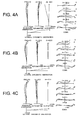
- Fig. 1 is a sectional view showing a lens configuration of an optical system according to Example 1 of the present application.
- the optical system according to Example 1 is composed of, in order from an object, a first lens group G1 having negative refractive power, and a second lens group G2 having positive refractive power.
- the first lens group G1 is composed of, in order from the object, a negative meniscus lens L11 having a convex surface facing the object, and a positive meniscus lens L12 having a convex surface facing the object.
- the negative meniscus lens L11 is an aspherical lens that a resin layer is applied on an image side glass surface and formed an aspherical surface thereon.
- the second lens group G2 is composed of, in order from the object, a double convex positive lens L21, a cemented lens constructed by a double convex positive lens L22 cemented with a double concave negative lens L23, and a cemented lens constructed by a double concave negative lens L24 cemented with a double convex positive lens L25.
- an air space between the first lens group G1 and the second lens group G2 is varied upon varying a focal length from the wide-angle end state to the telephoto end state.
- an aperture stop S is disposed in the second lens group G2, and moved together with the second lens group G2 upon varying a focal length from the wide-angle end state to the telephoto end state.
- the positive meniscus lens L12 in the first lens group G1 is an A lens. Since the A lens is disposed to the object side of the aperture stop S, the A lens has a positive meniscus shape having a convex surface facing the object, so that an incident angle of an oblique ray not parallel to the optical axis onto the A lens becomes close to the normal.
- f denotes a focal length
- Bf denotes a back focal length
- the left most column “i” shows the lens surface number counted in order from the object side
- the second column “r” shows a radius of curvature of the lens surface
- the third column “d” shows a distance to the next surface
- Bf denotes a back focal length. The position of an aspherical surface is expressed by attaching "*" to the right side of the surface number.
- y denotes a vertical height from the optical axis
- x denotes a sag amount which is a distance along the optical axis from the tangent surface at the vertex of the aspherical surface to the aspherical surface at the vertical height h from the optical axis
- r denotes a radius of curvature of a reference sphere (a paraxial radius of curvature)
- ⁇ denotes a conical coefficient
- FNO denotes an f-number
- 2 ⁇ denotes an angle of view in degrees
- Y denotes an image height
- TL denotes a total lens length
- W denotes a wide-angle end state
- M denotes an intermediate focal length state
- T denotes a telephoto end state.
- di denotes a variable distance at the surface number i where i is an integer.
- mm is generally used for the unit of length such as the focal length, the radius of curvature and the distance to the next lens surface.
- the unit is not necessarily to be limited to "mm", and any other suitable unit can be used.
- the explanation of reference symbols is the same in the other Examples, so that duplicated explanations are omitted.
- FNO denotes an f-number
- A denotes a half angle of view.
- f-number with respect to the maximum aperture is shown.
- f-number with respect to the maximum aperture is shown.
- coma coma with respect to each half angle of view is shown.
- astigmatism a solid line indicates a sagittal image plane, and a broken line indicates a meridional image plane.
- the optical system according to Example 1 shows superb optical performance as a result of good corrections to various aberrations in the wide-angle end state, in the intermediate focal length state, and in the telephoto end state.
- Fig. 3 is a sectional view showing a lens configuration of an optical system according to Example 2 of the present application.
- the optical system according to Example 2 is composed of, in order from an object, a first lens group G1 having negative refractive power, and a second lens group G2 having positive refractive power.
- the first lens group G1 is composed of, in order from the object, a negative meniscus lens L11 having a convex surface facing the object, and a positive meniscus lens L12 having a convex surface facing the object.
- the negative meniscus lens L11 is an aspherical lens that a resin layer is applied on an image side glass surface and formed an aspherical surface thereon.
- the second lens group G2 is composed of, in order from the object, a double convex positive lens L21, a cemented lens constructed by a double convex positive lens L22 cemented with a double concave negative lens L23, and a cemented lens constructed by a negative meniscus lens L24 having a convex surface facing the object cemented with a double convex positive lens L25.
- an air space between the first lens group G1 and the second lens group G2 is varied upon varying a focal length from the wide-angle end state to the telephoto end state.
- an aperture stop S is disposed in the second lens group G2, and moved together with the second lens group G2 upon varying a focal length from the wide-angle end state to the telephoto end state.
- the positive meniscus lens L12 in the first lens group G1 is an A lens. Since the A lens is disposed to the object side of the aperture stop S, the A lens has a positive meniscus shape having a convex surface facing the object, so that an incident angle of an oblique ray not parallel to the optical axis onto the A lens becomes close to the normal.
- the optical system according to Example 2 shows superb optical performance as a result of good corrections to various aberrations in the wide-angle end state, in the intermediate focal length state, and in the telephoto end state.
- Fig. 5 is a sectional view showing a lens configuration of an optical system according to Example 3 of the present application.
- the optical system according to Example 3 is composed of, in order from an object, a first lens group G1 having negative refractive power, a second lens group G2 having positive refractive power, and a third lens group G3 having negative refractive power.
- the first lens group G1 is composed of, in order from the object, a negative meniscus lens L11 having convex surface facing the object, a negative meniscus lens L12 having a convex surface facing the object, and a positive meniscus lens L13 having a convex surface facing the object.
- the negative meniscus lens L12 is an aspherical lens that a resin layer is applied on an image side glass surface and formed an aspherical surface thereon.
- the second lens group G2 is composed of, in order from the object, a cemented lens constructed by a double convex positive lens L21 cemented with a negative meniscus lens L22 having a concave surface facing the object, a cemented lens constructed by a double convex positive lens L23 cemented with a double concave negative lens L24, and a double convex positive lens L25.
- the third lens group G3 is composed of a negative meniscus lens L31 having a concave surface facing the object.
- varying a focal length is carried out by varying a distance between the first lens group G1 and the second lens group G2, and increasing a distance between the second lens group G2 and the third lens group G3.
- an aperture stop S is disposed in the second lens group G2, and moved together with the second lens group G2 upon varying a focal length from the wide-angle end state to the telephoto end state.
- the positive meniscus lens L13 in the first lens group G1 is an A lens. Since the A lens is disposed to the object side of the aperture stop S, the A lens has a positive meniscus shape having a convex surface facing the object, so that an incident angle of an oblique ray not parallel to the optical axis onto the A lens becomes close to the normal.
- the optical system according to Example 3 shows superb optical performance as a result of good corrections to various aberrations in the wide-angle end state, in the intermediate focal length state, and in the telephoto end state.
- Fig. 7 is a sectional view showing a lens configuration of an optical system according to Example 4 of the present application.
- the optical system according to Example 4 is composed of, in order from an object, a first lens group G1 having negative refractive power, a second lens group G2 having positive refractive power, and a third lens group G3 having negative refractive power.
- the first lens group G1 is composed of, in order from the object, a negative meniscus lens L11 having convex surface facing the object, a negative meniscus lens L12 having a convex surface facing the object, and a positive meniscus lens L13 having a convex surface facing the object.
- the negative meniscus lens L12 is an aspherical lens that a resin layer is applied on an image side glass surface and formed an aspherical surface thereon.
- the second lens group G2 is composed of, in order from the object, a cemented lens constructed by a double convex positive lens L21 cemented with a negative meniscus lens L22 having a concave surface facing the object, a cemented lens constructed by a double convex positive lens L23 cemented with a double concave negative lens L24, and a double convex positive lens L25.
- the third lens group G3 is composed of a negative meniscus lens L31 having a concave surface facing the object.
- varying a focal length from a wide-angle end state to a telephoto end state is carried out by varying a distance between the first lens group G1 and the second lens group G2, and increasing a distance between the second lens group G2 and the third lens group G3.
- an aperture stop S is disposed in the second lens group G2, and moved together with the second lens group G2 upon varying a focal length from the wide-angle end state to the telephoto end state.
- the positive meniscus lens L13 in the first lens group G1 is an A lens. Since the A lens is disposed to the object side of the aperture stop S, the A lens has a positive meniscus shape having a convex surface facing the object, so that an incident angle of an oblique ray not parallel to the optical axis onto the A lens becomes close to the normal.
- the optical system according to Example 4 shows superb optical performance as a result of good corrections to various aberrations in the wide-angle end state, in the intermediate focal length state, and in the telephoto end state.
- Fig. 9 is a sectional view showing a lens configuration of an optical system according to Example 5 of the present application.
- the optical system according to Example 5 is composed of, in order from an object, a first lens group G1 having negative refractive power, a second lens group G2 having positive refractive power, a third lens group G3 having negative refractive power, and a fourth lens group G4 having positive refractive power.
- the first lens group G1 is composed of, in order from the object, a negative meniscus lens L11 having a convex surface facing the object, a double concave negative lens L12, and a positive meniscus lens L13 having a convex surface facing the object.
- the negative meniscus lens L11 is an aspherical lens that a resin layer is applied on an image side glass surface and formed an aspherical surface thereon.
- the second lens group G2 is composed of, in order from the object, a cemented lens constructed by a negative meniscus lens L21 having a convex surface facing the object cemented with a double convex positive lens L22, and a positive meniscus lens L23 having a convex surface facing the object.
- the third lens group G3 is composed of a cemented lens constructed by, in order from the object, a positive meniscus lens L31 having a concave surface facing the object cemented with a double concave negative lens L32.
- the fourth lens group G4 is composed of, in order from the object, a plano-convex positive lens L41 having a plane surface facing the object, and a cemented lens constructed by a double convex positive lens L42 cemented with a negative meniscus lens L43 having a concave surface facing the object.
- varying a focal length from a wide-angle end state to a telephoto end state is carried out by varying a distance between the first lens group G1 and the second lens group G2, increasing a distance between the second lens group G2 and the third lens group G3, and decreasing a distance between the third lens group G3 and the fourth lens group G4.
- an aperture stop S is disposed to the object side of the third lens group G3, and moved together with the third lens group G3 upon varying a focal length from the wide-angle end state to the telephoto end state.
- the positive meniscus lens L31 in the third lens group G3 is an A lens. Since the A lens is disposed to the image side of the aperture stop S, the A lens has a meniscus shape having a concave surface facing the object, so that an incident angle of an oblique ray not parallel to the optical axis onto the A lens becomes close to the normal.
- the optical system according to Example 5 shows superb optical performance as a result of good corrections to various aberrations in the wide-angle end state, in the intermediate focal length state, and in the telephoto end state.
- Fig. 11 is a sectional view showing a lens configuration of an optical system according to Example 6 of the present application.
- the optical system according to Example 6 is composed of, in order from an object, a first lens group G1 having negative refractive power, a second lens group G2 having positive refractive power, a third lens group G3 having negative refractive power, and a fourth lens group G4 having positive refractive power.
- the first lens group G1 is composed of, in order from the object, a negative meniscus lens L11 having a convex surface facing the object, a double concave negative lens L12, and a positive meniscus lens L13 having a convex surface facing the object.
- the negative meniscus lens L11 is an aspherical lens that a resin layer is applied on an image side glass surface and formed an aspherical surface thereon.
- the second lens group G2 is composed of, in order from the object, a cemented lens constructed by a negative meniscus lens L21 having a convex surface facing the object cemented with a double convex positive lens L22, and a positive meniscus lens L23 having a convex surface facing the object.
- the third lens group G3 is composed of a cemented lens constructed by, in order from the object, a positive meniscus lens L31 having a concave surface facing the object cemented with a double concave negative lens L32.
- the fourth lens group G4 is composed of, in order from the object, a plano-convex positive lens L41 having a plane surface facing the object, and a cemented lens constructed by a double convex positive lens L42 cemented with a negative meniscus lens L43 having a concave surface facing the object.
- varying a focal length from a wide-angle end state to a telephoto end state is carried out by varying a distance between the first lens group G1 and the second lens group G2, increasing a distance between the second lens group G2 and the third lens group G3, and decreasing a distance between the third lens group G3 and the fourth lens group G4.
- an aperture stop S is disposed to the object side of the third lens group G3, and moved together with the third lens group G3 upon varying a focal length from the wide-angle end state to the telephoto end state.
- the positive meniscus lens L31 in the third lens group G3 is an A lens. Since the A lens is disposed to the image side of the aperture stop S, the A lens has a meniscus shape having a concave surface facing the object, so that an incident angle of an oblique ray not parallel to the optical axis onto the A lens becomes close to the normal.
- the optical system according to Example 6 shows superb optical performance as a result of good corrections to various aberrations in the wide-angle end state, in the intermediate focal length state, and in the telephoto end state.
- Fig. 13 is a sectional view showing a lens configuration of an optical system according to Example 7 of the present application.
- the optical system according to Example 7 is composed of, in order from an object, a first lens group G1 having negative refractive power, a second lens group G2 having positive refractive power, a third lens group G3 having negative refractive power, and a fourth lens group G4 having positive refractive power.
- the first lens group G1 is composed of, in order from the object, a negative meniscus lens L11 having a convex surface facing the object, a double concave negative lens L12, and a positive meniscus lens L13 having a convex surface facing the object.
- the negative meniscus lens L11 is an aspherical lens that a resin layer is applied on an image side glass surface and formed an aspherical surface thereon.
- the second lens group G2 is composed of, in order from the object, a cemented lens constructed by a negative meniscus lens L21 having a convex surface facing the object cemented with a double convex positive lens L22, and a positive meniscus lens L23 having a convex surface facing the object.
- the third lens group G3 is composed of a cemented lens constructed by, in order from the object, a positive meniscus lens L31 having a concave surface facing the object cemented with a double concave negative lens L32.
- the fourth lens group G4 is composed of, in order from the object, a plano-convex positive lens L41 having a plane surface facing the object, and a cemented lens constructed by a double convex positive lens L42 cemented with a negative meniscus lens L43 having a concave surface facing the object.
- varying a focal length from a wide-angle end state to a telephoto end state is carried out by varying a distance between the first lens group G1 and the second lens group G2, increasing a distance between the second lens group G2 and the third lens group G3, and decreasing a distance between the third lens group G3 and the fourth lens group G4.
- an aperture stop S is disposed to the object side of the third lens group G3, and moved together with the third lens group G3 upon varying a focal length from the wide-angle end state to the telephoto end state.
- the positive meniscus lens L31 in the third lens group G3 is an A lens. Since the A lens is disposed to the image side of the aperture stop S, the A lens has a meniscus shape having a concave surface facing the object, so that an incident angle of an oblique ray not parallel to the optical axis onto the A lens becomes close to the normal.
- the optical system according to Example 7 shows superb optical performance as a result of good corrections to various aberrations in the wide-angle end state, in the intermediate focal length state, and in the telephoto end state.
- Fig. 15 is a sectional view showing a lens configuration of an optical system according to Example 8 of the present application.
- the optical system according to Example 8 is composed of, in order from an object, a first lens group G1 having negative refractive power, a second lens group G2 having positive refractive power, a third lens group G3 having negative refractive power, and a fourth lens group G4 having positive refractive power.
- the first lens group G1 is composed of, in order from the object, a negative meniscus lens L11 having a convex surface facing the object, a double concave negative lens L12, and a positive meniscus lens L13 having a convex surface facing the object.
- the negative meniscus lens L11 is an aspherical lens that a resin layer is applied on an image side glass surface and formed an aspherical surface thereon.
- the second lens group G2 is composed of, in order from the object, a cemented lens constructed by a negative meniscus lens L21 having a convex surface facing the object cemented with a double convex positive lens L22, and a positive meniscus lens L23 having a convex surface facing the object.
- the third lens group G3 is composed of a cemented lens constructed by, in order from the object, a positive meniscus lens L31 having a concave surface facing the object cemented with a double concave negative lens L32.
- the fourth lens group G4 is composed of, in order from the object, a plano-convex positive lens L41 having a plane surface facing the object, and a cemented lens constructed by a double convex positive lens L42 cemented with a negative meniscus lens L43 having a concave surface facing the object.
- varying a focal length from a wide-angle end state to a telephoto end state is carried out by varying a distance between the first lens group G1 and the second lens group G2, increasing a distance between the second lens group G2 and the third lens group G3, and decreasing a distance between the third lens group G3 and the fourth lens group G4.
- an aperture stop S is disposed to the object side of the third lens group G3, and moved together with the third lens group G3 upon varying a focal length from the wide-angle end state to the telephoto end state.
- the positive meniscus lens L13 in the first lens group G1 is an A lens. Since the A lens is disposed to the object side of the aperture stop S, the A lens has a meniscus shape having a convex surface facing the object, so that an incident angle of an oblique ray not parallel to the optical axis onto the A lens becomes close to the normal.
- the optical system according to Example 8 shows superb optical performance as a result of good corrections to various aberrations in the wide-angle end state, in the intermediate focal length state, and in the telephoto end state.
- Fig. 17 is a sectional view showing a lens configuration of an optical system according to Example 9 of the present application.
- the optical system according to Example 9 is composed of, in order from an object, a first lens group G1 having negative refractive power, a second lens group G2 having positive refractive power, a third lens group G3 having negative refractive power, and a fourth lens group G4 having positive refractive power.
- the first lens group G1 is composed of, in order from the object, a negative meniscus lens L11 having a convex surface facing the object, a double concave negative lens L12, and a positive meniscus lens L13 having a convex surface facing the object.
- the negative meniscus lens L11 is an aspherical lens that a resin layer is applied on an image side glass surface and formed an aspherical surface thereon.
- the second lens group G2 is composed of, in order from the object, a cemented lens constructed by a negative meniscus lens L21 having a convex surface facing the object cemented with a double convex positive lens L22, and a positive meniscus lens L23 having a convex surface facing the object.
- the third lens group G3 is composed of a cemented lens constructed by, in order from the object, a positive meniscus lens L31 having a concave surface facing the object cemented with a double concave negative lens L32.
- the fourth lens group G4 is composed of, in order from the object, a plano-convex positive lens L41 having a plane surface facing the object, and a cemented lens constructed by a double convex positive lens L42 cemented with a negative meniscus lens L43 having a concave surface facing the object.
- varying a focal length from a wide-angle end state to a telephoto end state is carried out by varying a distance between the first lens group G1 and the second lens group G2, increasing a distance between the second lens group G2 and the third lens group G3, and decreasing a distance between the third lens group G3 and the fourth lens group G4.
- an aperture stop S is disposed to the object side of the third lens group G3, and moved together with the third lens group G3 upon varying a focal length from the wide-angle end state to the telephoto end state.
- the positive meniscus lens L13 in the first lens group G1 is an A lens. Since the A lens is disposed to the object side of the aperture stop S, the A lens has a meniscus shape having a convex surface facing the object, so that an incident angle of an oblique ray not parallel to the optical axis onto the A lens becomes close to the normal.
- the optical system according to Example 9 shows superb optical performance as a result of good corrections to various aberrations in the wide-angle end state, in the intermediate focal length state, and in the telephoto end state.
- Fig. 19 is a sectional view showing a lens configuration of an optical system according to Example 10 of the present application.
- the optical system according to Example 10 is composed of, in order from an object, a first lens group G1 having negative refractive power, a second lens group G2 having positive refractive power, a third lens group G3 having negative refractive power, and a fourth lens group G4 having positive refractive power.
- the first lens group G1 is composed of, in order from the object, a negative meniscus lens L11 having a convex surface facing the object, a double concave negative lens L12, and a positive meniscus lens L13 having a convex surface facing the object.
- the negative meniscus lens L11 is an aspherical lens that a resin layer is applied on an image side glass surface and formed an aspherical surface thereon.
- the second lens group G2 is composed of, in order from the object, a cemented lens constructed by a negative meniscus lens L21 having a convex surface facing the object cemented with a double convex positive lens L22, and a positive meniscus lens L23 having a convex surface facing the object.
- the third lens group G3 is composed of a cemented lens constructed by, in order from the object, a positive meniscus lens L31 having a concave surface facing the object cemented with a double concave negative lens L32.
- the fourth lens group G4 is composed of, in order from the object, a plano-convex positive lens L41 having a plane surface facing the object, and a cemented lens constructed by a double convex positive lens L42 cemented with a negative meniscus lens L43 having a concave surface facing the object.
- an aperture stop S is disposed to the object side of the third lens group G3.
- the positive meniscus lens L13 in the first lens group G1 is an A lens. Since the A lens is disposed to the object side of the aperture stop S, the A lens has a meniscus shape having a convex surface facing the object, so that an incident angle of an oblique ray not parallel to the optical axis onto the A lens becomes close to the normal.
- Table 10 [Lens Data] i r d nd ⁇ d 1 123.1562 1.90 1.51680 64.1 2 15.5000 0.17 1.55389 38.1 3* 13.3000 10.00 4 -183.9004 1.50 1.62299 58.2 5 53.4327 1.10 6 29.8607 3.10 2.00170 20.7 7 44.5512 32.95 8 34.0508 0.90 1.84666 23.8 9 18.0131 4.20 1.51823 58.9 10 -30.6255 0.10 11 19.8978 1.90 1.51823 58.9 12 40.4509 2.50 13 ⁇ 2.90 Aperture Stop S 14 -36.2369 2.75 1.85026 32.4 15 -10.7239 0.80 1.80400 46.6 16 96.3187 16.46 17 ⁇ 3.20 1.51823 58.9 18 -24.2955 0.10 19 138.8999 5.20 1.48749 70.5 20 -16.5664 1.30 1.85026 32.4 21 -
- the optical system according to Example 10 shows superb optical performance as a result of good corrections to various aberrations.
- each Example makes it possible to realize an optical system having excellent optical performance with sufficiently correcting spherical aberration and curvature of field.
- lens configuration of the optical system according to the present application is not limited to this, and other lens-group configurations such as a five-lens-group configuration can be applied.
- a portion of a lens group or a lens group may be moved along an optical axis as a focusing lens group.
- the focusing lens group may be used for an auto focus, and is suitable for being driven by a motor such as an ultrasonic motor.
- it is preferable that the first lens group or a portion of the first lens group is used as the focusing lens group.
- a lens group or a portion of a lens group may be shifted in a direction perpendicular to the optical axis as a vibration reduction lens group in order to correct an image blur caused by a camera shake, a lens group or a portion of a lens group of the other lens groups may be used as a vibration reduction lens group.
- a portion of the second lens group or a portion of the third lens group is used as a vibration reduction lens group.
- an aspherical lens may be used in other than the second lens group.
- the aspherical surface may be fabricated by a fine grinding process, a glass molding process that a glass material is formed into an aspherical shape by a mold, or a compound type process that a resin material is formed into an aspherical shape on a glass surface.
- An antireflection coating having high transmittance over a broad wavelength range may be applied to each lens surface of an optical system according to the present application to reduce flare or ghost images, so that high optical performance with a high contrast can be attained.
- a diffractive optical element may be easily used. With this configuration, it becomes possible to excellently correct chromatic aberration
- Fig. 21 is a schematic diagram showing a camera equipped with the optical system according to Example 1 of the present application.
- the camera 1 is a single-lens reflex digital camera equipped with the zoom lens system according to Example 1 as an image-taking lens 2.
- the camera 1 In the camera 1, light emitted from an object (not shown) is converged by the image-taking lens 2, and focused on a focusing screen 4 through a quick return mirror 3. The object image focused on the focusing screen 4 is reflected a plurality of times by a pentagonal roof prism 5, and led to an eyepiece 6. Therefore, a photographer can observe the object image as an erected image through the eyepiece 6.
- the quick return mirror 3 is removed from an optical path, and the light from the object (not shown) reaches an imaging device 7. Accordingly, light from the object is captured by the imaging device 7 and stored in a memory (not shown) as the object image. In this manner, the photographer can take a picture of the object by the camera 1.
- the optical system according to Example 1 of the present embodiment attached to the camera 1 as an image-taking lens 2 makes it possible to realize excellent optical performance with sufficiently correcting spherical aberration and curvature of field by means of the specific lens configuration. Accordingly, the camera 1 makes it possible to realize excellent optical performance with sufficiently correcting spherical aberration and curvature of field.
Priority Applications (2)
| Application Number | Priority Date | Filing Date | Title |
|---|---|---|---|
| EP13165428.7A EP2620796B1 (de) | 2007-08-21 | 2008-07-23 | Optisches System und Bildgebungsvorrichtung |
| EP11158079A EP2328008A3 (de) | 2007-08-21 | 2008-07-23 | Optisches System und Abbildungsvorrichtung |
Applications Claiming Priority (1)
| Application Number | Priority Date | Filing Date | Title |
|---|---|---|---|
| JP2007215116A JP5167724B2 (ja) | 2007-08-21 | 2007-08-21 | 光学系 |
Related Child Applications (1)
| Application Number | Title | Priority Date | Filing Date |
|---|---|---|---|
| EP13165428.7A Division EP2620796B1 (de) | 2007-08-21 | 2008-07-23 | Optisches System und Bildgebungsvorrichtung |
Publications (2)
| Publication Number | Publication Date |
|---|---|
| EP2028515A2 true EP2028515A2 (de) | 2009-02-25 |
| EP2028515A3 EP2028515A3 (de) | 2009-10-14 |
Family
ID=40039628
Family Applications (3)
| Application Number | Title | Priority Date | Filing Date |
|---|---|---|---|
| EP13165428.7A Expired - Fee Related EP2620796B1 (de) | 2007-08-21 | 2008-07-23 | Optisches System und Bildgebungsvorrichtung |
| EP08252492A Withdrawn EP2028515A3 (de) | 2007-08-21 | 2008-07-23 | Optisches System und Abbildungsvorrichtung |
| EP11158079A Withdrawn EP2328008A3 (de) | 2007-08-21 | 2008-07-23 | Optisches System und Abbildungsvorrichtung |
Family Applications Before (1)
| Application Number | Title | Priority Date | Filing Date |
|---|---|---|---|
| EP13165428.7A Expired - Fee Related EP2620796B1 (de) | 2007-08-21 | 2008-07-23 | Optisches System und Bildgebungsvorrichtung |
Family Applications After (1)
| Application Number | Title | Priority Date | Filing Date |
|---|---|---|---|
| EP11158079A Withdrawn EP2328008A3 (de) | 2007-08-21 | 2008-07-23 | Optisches System und Abbildungsvorrichtung |
Country Status (4)
| Country | Link |
|---|---|
| US (2) | US20090052051A1 (de) |
| EP (3) | EP2620796B1 (de) |
| JP (1) | JP5167724B2 (de) |
| CN (1) | CN101373262B (de) |
Families Citing this family (26)
| Publication number | Priority date | Publication date | Assignee | Title |
|---|---|---|---|---|
| JP5510770B2 (ja) * | 2008-09-18 | 2014-06-04 | 株式会社ニコン | 撮影レンズ、この撮影レンズを備えた光学機器 |
| KR101670054B1 (ko) * | 2009-10-14 | 2016-10-27 | 삼성전자 주식회사 | 줌 렌즈 및 이를 구비한 촬상 장치 |
| EP2579082A4 (de) * | 2010-05-28 | 2017-10-25 | Olympus Corporation | Optisches bildformungssystem und bildaufnahmevorrichtung |
| JP5582913B2 (ja) * | 2010-08-06 | 2014-09-03 | キヤノン株式会社 | 防振機能を有する単焦点レンズ |
| US9625689B2 (en) * | 2010-09-17 | 2017-04-18 | Nikon Corporation | Optical system, optical apparatus equipped therewith, and method for manufacturing optical system |
| JP5891447B2 (ja) | 2010-12-22 | 2016-03-23 | パナソニックIpマネジメント株式会社 | ズームレンズ系、交換レンズ装置及びカメラシステム |
| WO2012086153A1 (ja) * | 2010-12-22 | 2012-06-28 | パナソニック株式会社 | ズームレンズ系、交換レンズ装置及びカメラシステム |
| KR101355782B1 (ko) | 2010-12-29 | 2014-01-27 | 주식회사 나노포토닉스 | 어안 렌즈 |
| JP5724639B2 (ja) * | 2011-05-30 | 2015-05-27 | リコーイメージング株式会社 | ズームレンズ系及びこれを用いた光学機器 |
| JP2013015778A (ja) * | 2011-07-06 | 2013-01-24 | Konica Minolta Advanced Layers Inc | ズームレンズ,撮像光学装置及びデジタル機器 |
| JP6260075B2 (ja) * | 2012-08-30 | 2018-01-17 | 株式会社ニコン | 変倍光学系、及び、この変倍光学系を有する光学装置 |
| JP6098863B2 (ja) * | 2012-08-30 | 2017-03-22 | 株式会社ニコン | 変倍光学系、この変倍光学系を有する光学装置、及び、変倍光学系の製造方法 |
| JP6251947B2 (ja) * | 2012-08-30 | 2017-12-27 | 株式会社ニコン | 変倍光学系、この変倍光学系を有する光学装置、及び、変倍光学系の製造方法 |
| JP6256732B2 (ja) * | 2012-08-30 | 2018-01-10 | 株式会社ニコン | 変倍光学系、及び、この変倍光学系を有する光学装置 |
| IN2015DN01123A (de) * | 2012-08-30 | 2015-06-26 | Nikon Corp | |
| US9250425B2 (en) * | 2012-12-04 | 2016-02-02 | Samsung Electronics Co., Ltd. | Zoom lens and electronic device including the same |
| JP6226610B2 (ja) * | 2013-07-30 | 2017-11-08 | キヤノン株式会社 | ズームレンズ及びそれを有する撮像装置 |
| WO2015016004A1 (ja) | 2013-07-30 | 2015-02-05 | オリンパス株式会社 | ズームレンズ及びそれを備えたレンズ鏡筒、撮像装置 |
| JP6241142B2 (ja) * | 2013-08-29 | 2017-12-06 | 株式会社ニコン | 変倍光学系、光学装置、及び変倍光学系の製造方法 |
| JP6241143B2 (ja) * | 2013-08-29 | 2017-12-06 | 株式会社ニコン | 変倍光学系、光学装置、及び変倍光学系の製造方法 |
| JP5682715B2 (ja) * | 2014-01-06 | 2015-03-11 | 株式会社ニコン | ズームレンズ系、及び、このズームレンズ系を備えた光学機器 |
| CN107526155B (zh) * | 2017-08-31 | 2023-11-07 | 舜宇光学(中山)有限公司 | 玻塑混合定焦镜头 |
| CN112213846B (zh) * | 2019-07-09 | 2022-08-02 | Oppo广东移动通信有限公司 | 变焦镜头和电子装置 |
| JP7146708B2 (ja) * | 2019-08-12 | 2022-10-04 | 富士フイルム株式会社 | 撮像レンズおよび撮像装置 |
| CN112130300B (zh) * | 2020-10-20 | 2022-03-18 | 上海帛视光电科技有限公司 | 超广角成像光学系统 |
| CN114002832B (zh) * | 2021-10-29 | 2023-07-04 | 江西晶超光学有限公司 | 光学系统、镜头模组和电子设备 |
Citations (2)
| Publication number | Priority date | Publication date | Assignee | Title |
|---|---|---|---|---|
| JP2005134887A (ja) | 2003-10-08 | 2005-05-26 | Fujinon Corp | ズームレンズ |
| JP2007215116A (ja) | 2006-02-13 | 2007-08-23 | Fuji Xerox Co Ltd | 入力装置および画像処理装置 |
Family Cites Families (25)
| Publication number | Priority date | Publication date | Assignee | Title |
|---|---|---|---|---|
| US4818082A (en) * | 1988-05-27 | 1989-04-04 | Eastman Kodak Company | Compact wide-angle close-focus SLR zoom lens |
| JP3200925B2 (ja) * | 1992-03-05 | 2001-08-20 | 株式会社ニコン | 広画角を有するズームレンズ |
| US5825534A (en) * | 1992-04-28 | 1998-10-20 | Carl-Zeiss-Stiftung | Stereoendoscope having a folded sight line |
| JP3513264B2 (ja) * | 1995-04-25 | 2004-03-31 | キヤノン株式会社 | ズームレンズ及び撮影装置 |
| JP3517625B2 (ja) * | 1999-07-01 | 2004-04-12 | キヤノン株式会社 | 光学材料及びそれを用いた光学系 |
| JP4686888B2 (ja) * | 2000-04-20 | 2011-05-25 | 株式会社ニコン | ズームレンズ及び該レンズを備える撮影装置 |
| US20040125228A1 (en) * | 2001-07-25 | 2004-07-01 | Robert Dougherty | Apparatus and method for determining the range of remote objects |
| JP4082015B2 (ja) * | 2001-10-17 | 2008-04-30 | 株式会社ニコン | 液浸系顕微鏡対物レンズ |
| JP4551669B2 (ja) | 2004-02-26 | 2010-09-29 | キヤノン株式会社 | ズームレンズ及びそれを有する撮像装置 |
| US6989941B2 (en) * | 2003-10-08 | 2006-01-24 | Fujinon Corporation | Two-group zoom lens |
| JP2005134548A (ja) * | 2003-10-29 | 2005-05-26 | Sony Corp | ズームレンズ |
| JP4378188B2 (ja) | 2004-02-23 | 2009-12-02 | キヤノン株式会社 | ズームレンズ及びそれを有する撮像装置 |
| JP4817705B2 (ja) * | 2004-04-28 | 2011-11-16 | キヤノン株式会社 | 光学系 |
| US7116497B2 (en) * | 2004-04-28 | 2006-10-03 | Canon Kabushiki Kaisha | Retrofocus type optical system |
| JP4585794B2 (ja) * | 2004-05-31 | 2010-11-24 | キヤノン株式会社 | ズームレンズ及びそれを有する撮像装置 |
| JP4612810B2 (ja) * | 2004-06-11 | 2011-01-12 | キヤノン株式会社 | 光学系 |
| JP4794845B2 (ja) * | 2004-10-18 | 2011-10-19 | キヤノン株式会社 | ズームレンズ及びそれを有する撮像装置 |
| JP4630645B2 (ja) * | 2004-11-19 | 2011-02-09 | キヤノン株式会社 | 光学系 |
| US7403341B2 (en) | 2005-06-16 | 2008-07-22 | Olympus Imaging Corp. | Zoom lens system and electronic image pickup apparatus using the same |
| JP2007078801A (ja) * | 2005-09-12 | 2007-03-29 | Olympus Imaging Corp | ズームレンズ及びそれを有する電子撮像装置 |
| DE102005033746A1 (de) | 2005-07-15 | 2007-01-25 | Schott Ag | Kompaktes Objektiv zur digitalen Bilderfassung sowie Bilderfassungsvorrichtung |
| JP4859186B2 (ja) * | 2005-11-10 | 2012-01-25 | オリンパスイメージング株式会社 | ズームレンズ及びそれを備えた撮像装置 |
| US7471459B2 (en) | 2005-11-10 | 2008-12-30 | Olympus Imaging Corp. | Zoom lens system and image pickup apparatus using the same |
| JP4898200B2 (ja) | 2005-11-30 | 2012-03-14 | キヤノン株式会社 | ズームレンズ及びそれを有する撮像装置 |
| JP4909089B2 (ja) * | 2007-01-05 | 2012-04-04 | キヤノン株式会社 | ズームレンズ及びそれを有する撮像装置 |
-
2007
- 2007-08-21 JP JP2007215116A patent/JP5167724B2/ja not_active Expired - Fee Related
-
2008
- 2008-07-23 EP EP13165428.7A patent/EP2620796B1/de not_active Expired - Fee Related
- 2008-07-23 EP EP08252492A patent/EP2028515A3/de not_active Withdrawn
- 2008-07-23 EP EP11158079A patent/EP2328008A3/de not_active Withdrawn
- 2008-07-30 US US12/182,195 patent/US20090052051A1/en not_active Abandoned
- 2008-08-21 CN CN2008101308724A patent/CN101373262B/zh not_active Expired - Fee Related
-
2011
- 2011-01-12 US US13/005,063 patent/US8908283B2/en active Active
Patent Citations (2)
| Publication number | Priority date | Publication date | Assignee | Title |
|---|---|---|---|---|
| JP2005134887A (ja) | 2003-10-08 | 2005-05-26 | Fujinon Corp | ズームレンズ |
| JP2007215116A (ja) | 2006-02-13 | 2007-08-23 | Fuji Xerox Co Ltd | 入力装置および画像処理装置 |
Also Published As
| Publication number | Publication date |
|---|---|
| CN101373262A (zh) | 2009-02-25 |
| US8908283B2 (en) | 2014-12-09 |
| EP2028515A3 (de) | 2009-10-14 |
| US20110109977A1 (en) | 2011-05-12 |
| US20090052051A1 (en) | 2009-02-26 |
| EP2328008A3 (de) | 2012-10-17 |
| EP2328008A2 (de) | 2011-06-01 |
| EP2620796A2 (de) | 2013-07-31 |
| CN101373262B (zh) | 2012-11-28 |
| EP2620796A3 (de) | 2013-11-06 |
| JP5167724B2 (ja) | 2013-03-21 |
| EP2620796B1 (de) | 2018-08-22 |
| JP2009048012A (ja) | 2009-03-05 |
Similar Documents
| Publication | Publication Date | Title |
|---|---|---|
| EP2620796B1 (de) | Optisches System und Bildgebungsvorrichtung | |
| EP2360504B1 (de) | Zoomobjektivsystem, optische Vorrichtung und Verfahren zur Herstellung eines Zoomobjektivsystems | |
| EP2071379B1 (de) | Makro-Teleobjektiv mit drei Linsengruppen vom Frontfokus-Typ und Verfahren zu seiner Herstellung | |
| EP2397881B1 (de) | Retrofokus Zoomobjektiv mit vier Linsengruppen | |
| US10437026B2 (en) | Zoom lens system, imaging apparatus, and method for zooming the zoom lens system | |
| US7551367B2 (en) | Wide-angle lens, optical apparatus and method for focusing | |
| US9134516B2 (en) | Zoom lens, optical apparatus and method for manufacturing zoom lens | |
| US8144403B2 (en) | Zoom lens system, optical apparatus, and method for zooming | |
| CN108490592B (zh) | 变焦光学系统 | |
| US7924511B2 (en) | Optical system, method for focusing, and imaging apparatus equipped therewith | |
| EP1998204B1 (de) | Vibrationsbeständiges Telezoomobjektiv mit vier Linsengruppen vom Hinterfokus-Typ | |
| EP1870760A1 (de) | Retrofokus Zoom Objektiv mit vier Linsengruppen | |
| EP1881357A1 (de) | Vibrationsbeständiges Telezoomobjektiv mit vier Linsengruppen | |
| EP3242151A1 (de) | Retrofokus-linsensystem und bildaufnahmevorrichtung | |
| US9229199B2 (en) | Zoom lens system, imaging apparatus, and method for manufacturing zoom lens system | |
| US8259400B2 (en) | Zoom lens system, imaging apparatus, and method for manufacturing zoom lens system | |
| US7920341B2 (en) | Optical system, imaging apparatus, and method for forming image by the optical system | |
| EP2921897A1 (de) | Optische anordnung mit variabler leistung, optische vorrichtung und verfahren zur herstellung der optischen anordnung mit variabler leistung | |
| EP2916156A1 (de) | Optisches system mit variabler vergrösserung, optische vorrichtung und herstellungsverfahren für ein optisches system mit variabler vergrösserung |
Legal Events
| Date | Code | Title | Description |
|---|---|---|---|
| PUAI | Public reference made under article 153(3) epc to a published international application that has entered the european phase |
Free format text: ORIGINAL CODE: 0009012 |
|
| AK | Designated contracting states |
Kind code of ref document: A2 Designated state(s): AT BE BG CH CY CZ DE DK EE ES FI FR GB GR HR HU IE IS IT LI LT LU LV MC MT NL NO PL PT RO SE SI SK TR |
|
| AX | Request for extension of the european patent |
Extension state: AL BA MK RS |
|
| PUAL | Search report despatched |
Free format text: ORIGINAL CODE: 0009013 |
|
| AK | Designated contracting states |
Kind code of ref document: A3 Designated state(s): AT BE BG CH CY CZ DE DK EE ES FI FR GB GR HR HU IE IS IT LI LT LU LV MC MT NL NO PL PT RO SE SI SK TR |
|
| AX | Request for extension of the european patent |
Extension state: AL BA MK RS |
|
| RTI1 | Title (correction) |
Free format text: OPTICAL SYSTEM AND IMAGING APPARATUS. |
|
| 17P | Request for examination filed |
Effective date: 20100412 |
|
| 17Q | First examination report despatched |
Effective date: 20100519 |
|
| AKX | Designation fees paid |
Designated state(s): DE FR GB |
|
| RAP1 | Party data changed (applicant data changed or rights of an application transferred) |
Owner name: NIKON CORPORATION |
|
| STAA | Information on the status of an ep patent application or granted ep patent |
Free format text: STATUS: THE APPLICATION IS DEEMED TO BE WITHDRAWN |
|
| 18D | Application deemed to be withdrawn |
Effective date: 20110909 |