EP2028370A2 - Windgetriebener Generator und Anordnungen damit - Google Patents
Windgetriebener Generator und Anordnungen damit Download PDFInfo
- Publication number
- EP2028370A2 EP2028370A2 EP07111880A EP07111880A EP2028370A2 EP 2028370 A2 EP2028370 A2 EP 2028370A2 EP 07111880 A EP07111880 A EP 07111880A EP 07111880 A EP07111880 A EP 07111880A EP 2028370 A2 EP2028370 A2 EP 2028370A2
- Authority
- EP
- European Patent Office
- Prior art keywords
- gear
- wind
- electrical
- generator
- shaft
- Prior art date
- Legal status (The legal status is an assumption and is not a legal conclusion. Google has not performed a legal analysis and makes no representation as to the accuracy of the status listed.)
- Granted
Links
Images


Classifications
-
- F—MECHANICAL ENGINEERING; LIGHTING; HEATING; WEAPONS; BLASTING
- F03—MACHINES OR ENGINES FOR LIQUIDS; WIND, SPRING, OR WEIGHT MOTORS; PRODUCING MECHANICAL POWER OR A REACTIVE PROPULSIVE THRUST, NOT OTHERWISE PROVIDED FOR
- F03D—WIND MOTORS
- F03D13/00—Assembly, mounting or commissioning of wind motors; Arrangements specially adapted for transporting wind motor components
- F03D13/10—Assembly of wind motors; Arrangements for erecting wind motors
-
- F—MECHANICAL ENGINEERING; LIGHTING; HEATING; WEAPONS; BLASTING
- F03—MACHINES OR ENGINES FOR LIQUIDS; WIND, SPRING, OR WEIGHT MOTORS; PRODUCING MECHANICAL POWER OR A REACTIVE PROPULSIVE THRUST, NOT OTHERWISE PROVIDED FOR
- F03D—WIND MOTORS
- F03D1/00—Wind motors with rotation axis substantially parallel to the air flow entering the rotor
-
- F—MECHANICAL ENGINEERING; LIGHTING; HEATING; WEAPONS; BLASTING
- F03—MACHINES OR ENGINES FOR LIQUIDS; WIND, SPRING, OR WEIGHT MOTORS; PRODUCING MECHANICAL POWER OR A REACTIVE PROPULSIVE THRUST, NOT OTHERWISE PROVIDED FOR
- F03D—WIND MOTORS
- F03D15/00—Transmission of mechanical power
-
- F—MECHANICAL ENGINEERING; LIGHTING; HEATING; WEAPONS; BLASTING
- F03—MACHINES OR ENGINES FOR LIQUIDS; WIND, SPRING, OR WEIGHT MOTORS; PRODUCING MECHANICAL POWER OR A REACTIVE PROPULSIVE THRUST, NOT OTHERWISE PROVIDED FOR
- F03D—WIND MOTORS
- F03D15/00—Transmission of mechanical power
- F03D15/10—Transmission of mechanical power using gearing not limited to rotary motion, e.g. with oscillating or reciprocating members
-
- F—MECHANICAL ENGINEERING; LIGHTING; HEATING; WEAPONS; BLASTING
- F03—MACHINES OR ENGINES FOR LIQUIDS; WIND, SPRING, OR WEIGHT MOTORS; PRODUCING MECHANICAL POWER OR A REACTIVE PROPULSIVE THRUST, NOT OTHERWISE PROVIDED FOR
- F03D—WIND MOTORS
- F03D80/00—Details, components or accessories not provided for in groups F03D1/00 - F03D17/00
-
- F—MECHANICAL ENGINEERING; LIGHTING; HEATING; WEAPONS; BLASTING
- F03—MACHINES OR ENGINES FOR LIQUIDS; WIND, SPRING, OR WEIGHT MOTORS; PRODUCING MECHANICAL POWER OR A REACTIVE PROPULSIVE THRUST, NOT OTHERWISE PROVIDED FOR
- F03D—WIND MOTORS
- F03D9/00—Adaptations of wind motors for special use; Combinations of wind motors with apparatus driven thereby; Wind motors specially adapted for installation in particular locations
- F03D9/10—Combinations of wind motors with apparatus storing energy
- F03D9/11—Combinations of wind motors with apparatus storing energy storing electrical energy
-
- F—MECHANICAL ENGINEERING; LIGHTING; HEATING; WEAPONS; BLASTING
- F03—MACHINES OR ENGINES FOR LIQUIDS; WIND, SPRING, OR WEIGHT MOTORS; PRODUCING MECHANICAL POWER OR A REACTIVE PROPULSIVE THRUST, NOT OTHERWISE PROVIDED FOR
- F03D—WIND MOTORS
- F03D9/00—Adaptations of wind motors for special use; Combinations of wind motors with apparatus driven thereby; Wind motors specially adapted for installation in particular locations
- F03D9/20—Wind motors characterised by the driven apparatus
- F03D9/25—Wind motors characterised by the driven apparatus the apparatus being an electrical generator
-
- F—MECHANICAL ENGINEERING; LIGHTING; HEATING; WEAPONS; BLASTING
- F05—INDEXING SCHEMES RELATING TO ENGINES OR PUMPS IN VARIOUS SUBCLASSES OF CLASSES F01-F04
- F05B—INDEXING SCHEME RELATING TO WIND, SPRING, WEIGHT, INERTIA OR LIKE MOTORS, TO MACHINES OR ENGINES FOR LIQUIDS COVERED BY SUBCLASSES F03B, F03D AND F03G
- F05B2250/00—Geometry
- F05B2250/80—Size or power range of the machines
-
- F—MECHANICAL ENGINEERING; LIGHTING; HEATING; WEAPONS; BLASTING
- F05—INDEXING SCHEMES RELATING TO ENGINES OR PUMPS IN VARIOUS SUBCLASSES OF CLASSES F01-F04
- F05B—INDEXING SCHEME RELATING TO WIND, SPRING, WEIGHT, INERTIA OR LIKE MOTORS, TO MACHINES OR ENGINES FOR LIQUIDS COVERED BY SUBCLASSES F03B, F03D AND F03G
- F05B2260/00—Function
- F05B2260/40—Transmission of power
- F05B2260/403—Transmission of power through the shape of the drive components
- F05B2260/4031—Transmission of power through the shape of the drive components as in toothed gearing
-
- Y—GENERAL TAGGING OF NEW TECHNOLOGICAL DEVELOPMENTS; GENERAL TAGGING OF CROSS-SECTIONAL TECHNOLOGIES SPANNING OVER SEVERAL SECTIONS OF THE IPC; TECHNICAL SUBJECTS COVERED BY FORMER USPC CROSS-REFERENCE ART COLLECTIONS [XRACs] AND DIGESTS
- Y02—TECHNOLOGIES OR APPLICATIONS FOR MITIGATION OR ADAPTATION AGAINST CLIMATE CHANGE
- Y02E—REDUCTION OF GREENHOUSE GAS [GHG] EMISSIONS, RELATED TO ENERGY GENERATION, TRANSMISSION OR DISTRIBUTION
- Y02E10/00—Energy generation through renewable energy sources
- Y02E10/70—Wind energy
- Y02E10/72—Wind turbines with rotation axis in wind direction
Definitions
- This invention relates to wind-powered generators, and more particularly to wind-powered generators for powering relatively small electronic devices.
- an alternative source for electricity is often desirable, particularly for providing illumination. Often in such a situation, batteries for flashlights are not on hand or no longer provide a charge.
- Generators can be relatively large and inconvenient for use with small devices. Wind-powered generators convert the kinetic energy in the wind into mechanical energy, which is then converted into electricity.
- One of the advantages of the present invention is that it provides a small portable wind-powered generator assembly for use as such an alternative source of electricity that is not connected to a power grid, and can be used to power small devices.
- a wind-powered electrical assembly comprising an electrical device; an electrical generator, the electrical generator electrically connected to the electrical device, the electrical generator operable to provide an electric current to the electrical device to operate the electrical device, the electrical generator having a rotor; a wind-powered actuator assembly configured to rotate when subject to an operating wind; and a gear train arranged with the electrical generator for operating the electrical generator, the gear train including a plurality of transfer gears wherein a first gear is operably arranged with a spring assembly, the spring assembly having a reel mounted to the shaft of the first gear and a tape spring for rotationally biasing the reel to rotate in a return direction, the tape spring being wound on the reel and connected such that when the shaft is moved in an operating direction, the reel rotates in a forward direction and the tape spring develops a return force, the return force urging the reel and the shaft of the first gear to move in a return direction, the return direction opposing the forward direction, a second gear of the gear train being operably arranged with the wind-powered actuator
- the gear train includes at least eight transfer gears.
- the gear train may also include a spring pawl mechanism operably engaged with the shaft of the first gear.
- the wind-powered actuator assembly may include a shaft, a rotor, and at least one blade attached to the rotor, the at least one blade configured to rotate around an axis by the shaft in an operating direction when exposed to an operating wind.
- the electrical device may further be a light source, a fan or a mobile telephone.
- the invention may further comprise an aerodynamic housing surrounding the gear train and the electrical generator, wherein the housing is configured to present minimised interference to an operating wind.
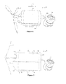
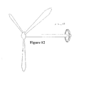
- FIG. 1 a light assembly 50 according to one embodiment of the present invention including a wind-powered generator assembly 52 including an electrical generator device (not shown) contained within a housing 54, a wind actuator assembly 56, and a light source 58.
- the electrical generator is electrically connected to the light source 58 and is operable to provide an electric current to the light source 58 to operate the light source for providing light.
- the housing 54 may be opened to expose the generator device 60.
- the wind-powered generator assembly 52 comprises a generator 64, a gear train 66, a spring housing 68, a wind actuator assembly 56 including plurality of blades 70, 72, 74 and a shaft 76, a frame 78, and a rechargeable battery 80.
- the blades 70, 72, 74 of the wind actuator assembly 56 are coupled to the shaft 76 via a rotor 82 to power rotation of the shaft 76 in an operating direction.
- the shaft 76 is operatively coupled to the gear train 66.
- the spring pawl 86 mechanism is embedded within the gear train 66, thereby dividing the gear train 66 into an actuator section 88 and a generator section 90. Referring to FIG.
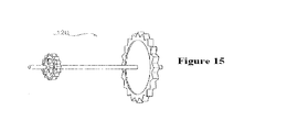
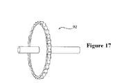
- the spring pawl mechanism 86 is operably arranged with the shaft 96 of the fifth transfer gear 92, which is part of the actuator section 88 of the gear train 66.
- the spring pawl mechanism 86 is operably connected to the shaft 76 of the wind actuator assembly 56 via the actuator section 88 of the gear train 66 in order to prevent the shaft 76 from rotating in a direction opposite the operating direction.
- the spring housing 68 is connected to the shaft 96 of the fifth transfer gear 92 such that a tape spring within the spring housing 68 is wound upon rotational movement of the shaft 96 in the operating direction.
- the spring housing 68 is also operably arranged with the generator section 90 of the gear train 66 for providing rotational movement of the generator section 90 when the tape spring is unwound.
- the generator section 90 of the gear train 66 in turn, is operably arranged with the generator 64 such that the rotational movement of the gear train 66 is converted to electricity by the generator 64.
- the generator 64 is electrically connected to the rechargeable battery 80 by a cable 222.
- the rechargeable battery 80 is electrically connected to the light source 58 by cable 224 to provide electricity thereto.
- the frame 78 is used to mount and support components of the electrical generator device 60.
- the housing 54 is provided to contain and protect components of the electrical generator device.
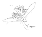
- the housing 54 embodies an aerodynamic design without any sharp edges that is configured to present minimised interference to an operating wind.
- An operating wind is air flowing over the housing 54 from the front end 100 to the rear end 102 of the housing 54 in a direction 104.
- the wind actuator assembly 56 projects from the front end 100 of the housing 54 in order to receive the operating wind.
- the housing 54 can have a generally cylindrical body 106 wherein the rear end 102 is generally flat and circular.
- the front end 100 of the housing may include an upper section 103, a middle section 105, and a lower section 107.
- the front end 100 may generally taper to the middle section 105, which represents the forwardmost part of the housing 54.
- the upper section 103 may initially descend vertically from the body 106 and then extend down and forward to the middle section 105 along a concave curve.
- the lower section 105 may extend up to middle section 105 along a generally conical path.
- the wind actuator assembly 56 extends forward from the upper section 103 such that the rotor is located generally in front of the upper section 103.
- the wind-powered generator assembly may have other types of housings.
- the housing may not be aerodynamic.
- the housing may include legs or may be mounted on top of a tower or building in order to better harness an operating wind.
- the wind-powered generator may not include a housing.
- the housing may include an upper half 112 and a bottom half 114 that are separable.
- the upper half 112 may be removed from the bottom half 114 to expose the generator device 60.
- the bottom half 114 may cradle the generator device 60 and the battery 80.
- the wind actuator assembly 56 is operated by an operating wind travelling in a direction 104 towards the wind actuator assembly 56.
- the wind-powered generator assembly 52 is arranged such that the front end 100 faces into the wind.
- the blades 70, 72, (74 not shown) of the wind actuator 56 are configured such that wind travelling in a direction 104 will force the blades 70, 72, 74, and thereby the rotor 108 and shaft 76, to rotate in the operating direction.
- the wind actuator assembly may have a different number of blades or differently configured blades.
- the wind actuator assembly may be a vertical axis wind actuator such as, for example, a Darrieus type wind actuator.
- the shaft 76 transmits the rotational force generated by the wind actuator assembly 56 to the electrical generator 64 through the gear train 66 to generate electricity.
- the aerodynamic design of the housing 54 facilitates the flow of an operating wind through the wind-powered generator assembly 52 to increase the wind power harnessed by the wind actuator assembly 56 and transmitted to the electrical generator 64.
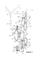
- the operable arrangement of the wind actuator assembly 56, the gear train 66, and the electrical generator 64 is shown in FIG. 7 .
- the wind actuator assembly 56 includes first, second, and third blades 70, 72, 74 connected to a rotor 108.
- the wind actuator assembly 56 further includes a shaft 76 connecting the rotor 108 to a wind actuator gear 110.
- the wind actuator gear 110 is operably connected to the gear train 66.
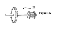
- the gear train 66 includes eight transfer gears 92, 116, 118, 120, 122, 124, 126, 128 and a spring housing gear 130.
- the transfer gears 92, 116, 118, 120, 122, 124, 126, 128 and the spring housing gear 130 transmit rotational force from the wind actuator gear 110 to the generator 64.
- Each transfer gear 92, 116, 118, 120, 122, 124, 126, 128 includes a shaft 96, 132, 134, 136, 138, 140, 142 ,144 and a driven gear 146, 148, 150, 152 154, 156, 158, 160 for receiving rotational force.
- the driven gear or the driving gear on any of the transfer gears can be a spur gear or a rod combination unit.
- the wind actuator gear 110 is operably engaged with the actuator section 88 of the gear train 66, which includes the first, second, third, fourth, and fifth transfer gears 116, 118, 120, 122, 92.
- the actuator section 88 of the gear train 66 transmits rotational force in the operating direction to the spring housing 68.
- the driven gear 154 of the fifth transfer gear 92 is operably engaged with the driving gear 168 of the fourth transfer gear 122 while the shaft 96 of the fifth transfer gear 92 passes through the first frame plate 180 to operably attach to the spring housing 68.
- a spring ratchet gear 182 is attached to the shaft 96 of the fifth transfer gear 92 on the actuator side of the first frame plate 180.
- the spring pawl mechanism 86 is mounted to the actuator side of the first plate 180 and operably engaged with the spring ratchet gear 182.
- the spring housing 68 is operably attached to the spring housing gear 130, which, together with the sixth, seventh, and eighth transfer gears 124, 126, 128, constitutes the generator section 90 of the gear train 66.
- the generator section 90 of the gear train 66 transmits rotational force in the operating direction to the electrical generator 64.
- the generator 64 includes a rotor 190 and a driven gear 192.
- the driven gear 192 of the rotor 190 receives the rotational force from gear train 66 and the electrical generator 64 uses the rotational energy to produce electricity.
- the frame 78 comprises first and second plates 180, 194 disposed in spaced relationship to each other with the spring housing 68, the gear train 66, and the generator 64 supported by the plates 180, 194.
- the first plate 180 shown in FIG. 9
- four connecting rods 200, 202, 204, 206 are secured to the plates 180, 194.
- the connecting rods 200, 202, 204, 206 can secure the plates 180, 194 together.
- the connecting rods 200, 202, 204, 206 may pass through holes in the plates 180, 194 and can be secured on either end to the first and second plates 180, 194 by nuts.
- the spring housing 68 and the generator 64 are disposed generally between the plates 180, 194, as shown in FIG. 4 .
- the shafts of the transfer gears are rotatably mounted to at least one of the plates 180, 194 such that the transfer gears are free to rotate with respect to the plates 180, 194 along an axis defined by each respective shaft.
- the driven gear 146 of the first transfer gear 116 is operably arranged with the wind actuator gear 110 such that rotation of the wind actuator gear 110 rotates the first transfer gear 116.
- the driving gear 162 of the first transfer gear 116 is operably arranged with the driven gear 148 of the second transfer gear 118 such that rotation of the first transfer gear 116 also rotates the second transfer gear 118.
- the driving gear 164 of the second transfer gear 118 is operably arranged with the driven gear 150 of the third transfer gear 120 such that rotation of the second transfer gear 118 also rotates the third transfer gear 120.
- the driving gear 166 of the third transfer gear 120 is operably arranged with the driven gear 152 of the fourth transfer gear 122 such that rotation of the third transfer gear 120 also rotates the fourth transfer gear 122.
- the driving gear 168 of the fourth transfer gear 122 is operably arranged with the driven gear 154 of the fifth transfer gear 92 such that rotation of the fourth transfer gear 122 also rotates the fifth transfer gear 92.
- the shaft 96 of the fifth transfer gear 92 is operably arranged with the spring housing 68 such that the rotation of the fifth transfer gear 92 also rotates the spring housing gear 130.
- the spring pawl mechanism 86 and spring ratchet gear 182 ensure that the fifth transfer gear 92 only rotates in the operating direction.
- the spring housing gear 130 is operably arranged with the driven gear 156 of the sixth transfer gear 124 such that rotation of the spring housing gear 130 also rotates the sixth transfer gear 124.
- the driving gear 170 of the sixth transfer gear 124 is operably arranged with the driven gear 158 of the seventh transfer gear 126 such that rotation of the sixth transfer gear 124 also rotates the seventh transfer gear 126.
- the driving gear 172 of the seventh transfer gear 128 is operably arranged with the driven gear 160 of the eighth transfer gear 128 such that rotation of the seventh transfer gear 126 also rotates the eighth transfer gear 128.
- the driving gear 174 of the eighth transfer gear 128 is operably arranged with the driven gear 192 of the generator 64 such that the generator creates electricity when the eighth transfer gear 128 is rotated.
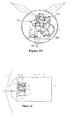
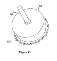
- the spring housing 68 includes a reel 210, a tape spring disposed within the reel 210, the spring housing gear 130 secured to the reel 210, and an extension member 212 extending from the spring housing gear 130.
- the shaft 96 of the fifth transfer gear 92 is operably arranged with the spring housing 68, as shown in FIG. 18 .
- the spring housing 68 is supported by the first plate 180 via the shaft 96 of the fifth transfer gear 92.
- the shaft 96 is rotatably supported within a mounting hole of the plate 180 such that the shaft 96 is free to rotate with respect to the plate 180.
- the spring housing 68 is supported by the second plate 194 via the extension member.
- the extension member is rotatably supported within a mounting hole of the plate 194 such that the spring housing gear 130 is free to rotate with respect to the plate 194.
- the spring pawl mechanism 86 includes a spring pawl that is engaged with a spring ratchet gear 182.
- the spring ratchet gear 182 is mounted to the shaft 96 of the fifth transfer gear 92.
- the spring pawl 86 is pivotally mounted to the actuator side of the first plate 180.
- a biasing member 214 is provided to urge the spring pawl 86 into operative engagement with the spring ratchet gear 182.
- the biasing member 214 is mounted to the actuator side of the first plate 180.
- a return stop member is mounted to the first plate and is arranged with the spring ratchet gear.
- the rotation of the shaft 96 of the fifth transfer gear 92 in the operating direction winds the tape spring around the reel portion of the shaft 96.
- the winding of the tape spring creates a spring force, which is exerted against the reel portion of the shaft 96 in the return direction.
- the spring pawl mechanism 86 resists this force on the shaft 96, resulting in the tape spring urging the spring housing 68 and the spring housing gear 130 to rotate in the forward, operating direction as the tape spring unwinds.
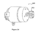
- the generator 64 is relatively cylindrical in shape.
- the generator comprises a body 216, a shaft 218, a driven gear 192, and a bracket 220.
- the shaft 218 extends from the body 216 with the driven gear 192 disposed at a distal end thereof.
- the driving gear 174 of the eighth transfer gear 128 is in operable position with the driven gear 192 of the generator 64 such that when the eighth transfer gear 128 rotates, the driven gear 182 will rotate the shaft 218 resulting in the generation of electrical energy by the generator 64.
- the mounting bracket 220 can be used to mount the generator 64 to the second plate.
- the driven gear 192 is a rod-combination.
- the driven gear 302 can be a spur gear.
- the rechargeable battery or battery pack 80 can be connected to the generator such that the electricity created by the generator can be stored and used at a later point in time rather than immediately during operation of the generator.
- a cable 222 can be used to connect the battery 80 to the generator.
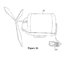
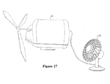
- the wind-powered generator assembly 52 can be used to power items such as the light source 58 (as shown in FIG. 1 ), a mobile phone 224 (as shown in FIG. 26 ), or a fan 226 (as shown in FIG. 27 ).
- the wind-powered generator device 52 can be connected to more than one device at a time, e.g. the assembly can include a light source 58 and other devices such as the fan 226 and the mobile phone 224.
- the manual-powered generator can be used to power any suitable electrically-powered device.
Landscapes
- Engineering & Computer Science (AREA)
- Life Sciences & Earth Sciences (AREA)
- Sustainable Development (AREA)
- Sustainable Energy (AREA)
- Chemical & Material Sciences (AREA)
- Combustion & Propulsion (AREA)
- Mechanical Engineering (AREA)
- General Engineering & Computer Science (AREA)
- Power Engineering (AREA)
- Wind Motors (AREA)
- Connection Of Motors, Electrical Generators, Mechanical Devices, And The Like (AREA)
Applications Claiming Priority (1)
| Application Number | Priority Date | Filing Date | Title |
|---|---|---|---|
| US11/809,181 US7851937B2 (en) | 2007-05-31 | 2007-05-31 | Wind-powered generator and assemblies therewith |
Publications (3)
| Publication Number | Publication Date |
|---|---|
| EP2028370A2 true EP2028370A2 (de) | 2009-02-25 |
| EP2028370A3 EP2028370A3 (de) | 2013-09-11 |
| EP2028370B1 EP2028370B1 (de) | 2015-01-14 |
Family
ID=40087282
Family Applications (1)
| Application Number | Title | Priority Date | Filing Date |
|---|---|---|---|
| EP07111880.6A Active EP2028370B1 (de) | 2007-05-31 | 2007-07-05 | Windgetriebener Generator und Anordnungen damit |
Country Status (9)
| Country | Link |
|---|---|
| US (1) | US7851937B2 (de) |
| EP (1) | EP2028370B1 (de) |
| JP (1) | JP5011212B2 (de) |
| CN (2) | CN101315062B (de) |
| AU (1) | AU2008202028B2 (de) |
| CA (1) | CA2630195C (de) |
| ES (1) | ES2534607T3 (de) |
| NZ (1) | NZ568037A (de) |
| TW (1) | TWI354731B (de) |
Families Citing this family (13)
| Publication number | Priority date | Publication date | Assignee | Title |
|---|---|---|---|---|
| US7851937B2 (en) * | 2007-05-31 | 2010-12-14 | Awa Micro Power Corporation Limited | Wind-powered generator and assemblies therewith |
| NO329597B1 (no) * | 2009-01-28 | 2010-11-22 | Fobox As | Drivanordning for en vindmolle |
| CN101798992B (zh) * | 2009-02-06 | 2012-07-18 | 广州均和纳米新材料科技有限公司 | 多风向匀速风力发电机 |
| EP2317137B1 (de) * | 2009-11-02 | 2012-07-25 | General Electric Company | Konfiguration einer Windturbinengondel |
| US20110168459A1 (en) * | 2010-01-08 | 2011-07-14 | Fortune One, Llc | Mobile Kinetic Wind Generator System |
| NO334466B1 (no) * | 2010-04-27 | 2014-03-10 | Fobox As | En drivanordning |
| CN102759018A (zh) * | 2011-04-28 | 2012-10-31 | 李跃明 | 自发电手电筒 |
| US20120292913A1 (en) * | 2011-05-19 | 2012-11-22 | Turck Jeffrey W | Windmill |
| CN102644560B (zh) * | 2012-05-17 | 2014-02-05 | 福建明业新能源科技有限公司 | 小型风力发电机的防止电缆扭断装置 |
| JP6065505B2 (ja) * | 2012-10-03 | 2017-01-25 | 株式会社ジェイテクト | 発電装置 |
| BR112017019058A2 (pt) * | 2015-03-30 | 2018-04-17 | Vestas Wind Sys As | turbina eólica compreendendo dois ou mais rotores |
| EP3277951A1 (de) * | 2015-03-30 | 2018-02-07 | Vestas Wind Systems A/S | Windturbine mit einem rotor mit hohlem achsschenkelbolzen |
| CN114142652B (zh) * | 2021-11-15 | 2023-02-28 | 杭州爱纬斯电子有限公司 | 一种节能直流电机 |
Citations (2)
| Publication number | Priority date | Publication date | Assignee | Title |
|---|---|---|---|---|
| SU1574899A1 (ru) | 1988-07-26 | 1990-06-30 | А.А.Рахматов и Ш.А.Рахматов | Ветроагрегат |
| EP1691128A2 (de) | 2005-02-09 | 2006-08-16 | Wo Huen Poon | Handbetriebener Generator und Baugruppen damit |
Family Cites Families (30)
| Publication number | Priority date | Publication date | Assignee | Title |
|---|---|---|---|---|
| US983742A (en) * | 1910-04-20 | 1911-02-07 | Albert H Deremo | Electric hand-lamp. |
| US1131063A (en) * | 1912-02-19 | 1915-03-09 | Conrad Klemmer | Portable magneto-electric machine. |
| US1487502A (en) * | 1922-05-04 | 1924-03-18 | Gen Electric | Magneto flash lamp |
| US2105719A (en) * | 1935-10-08 | 1938-01-18 | Cap B Collins | Portable electric light |
| US2424700A (en) * | 1944-11-11 | 1947-07-29 | Dayton Acme Co | Generator light |
| US2525817A (en) * | 1945-05-31 | 1950-10-17 | Macadams Jesse Edward | Generator |
| US3961577A (en) * | 1975-05-12 | 1976-06-08 | The United States Of America As Represented By The Secretary Of The Navy | Air driven energy storing fuze safing and arming mechanism |
| JPS5681271A (en) * | 1979-12-04 | 1981-07-03 | Maesato Teruko | Method for automatically winding spring and generating method and device |
| JPS5681270A (en) * | 1979-12-06 | 1981-07-03 | Akihaya Mizukami | Power device for wind mill |
| JPS56101079A (en) * | 1980-01-17 | 1981-08-13 | Sakuji Kajiyama | Energy storing device |
| US4890528A (en) * | 1987-06-15 | 1990-01-02 | Kabushiki Kaisha Sankyo Seiki Seisakusho | Music box having a generator |
| JP2515037Y2 (ja) * | 1990-01-30 | 1996-10-23 | 宮田工業株式会社 | 三輪自転車用スタンド |
| JPH03123346U (de) * | 1990-03-28 | 1991-12-16 | ||
| WO1996012106A1 (en) * | 1994-10-17 | 1996-04-25 | Wai Cheung Lee | Fluid power storage device |
| US5796240A (en) * | 1995-02-22 | 1998-08-18 | Seiko Instruments Inc. | Power unit and electronic apparatus equipped with power unit |
| US5982577A (en) * | 1995-03-31 | 1999-11-09 | Brown; Paul | Batteryless, spring-powered portable cassette player |
| US5880532A (en) * | 1996-09-20 | 1999-03-09 | Estate Of Robert Stopher | Wind-up power source with spring motor and vehicle incorporating same |
| JPH10127012A (ja) * | 1996-10-15 | 1998-05-15 | Sony Corp | 発電装置 |
| JP2001115945A (ja) * | 1999-10-14 | 2001-04-27 | Mitsuo Honda | 乗物搭載型風力発電装置 |
| JP2001329945A (ja) * | 2000-03-17 | 2001-11-30 | Seiko Epson Corp | 温度差駆動装置およびそれを備えた電子機器 |
| WO2002033255A1 (en) * | 2000-10-16 | 2002-04-25 | Seiko Epson Corporation | Power spring mechanism and equipment having the mechanism |
| US6433450B1 (en) * | 2000-11-28 | 2002-08-13 | Wen-Ping Chao | Power generating system with physical energy to enhance output |
| DE60134282D1 (de) * | 2000-12-22 | 2008-07-10 | Freeplay Market Dev Ltd | Handgehaltenegenerator |
| JP2004190581A (ja) * | 2002-12-11 | 2004-07-08 | Seiko Epson Corp | ゼンマイ機構、ゼンマイ機構の製造方法及び製造装置並びにこれを用いた機器 |
| US6707191B1 (en) * | 2003-05-05 | 2004-03-16 | Pontiac Coil, Inc. | Clockspring generator |
| US7009350B1 (en) * | 2004-02-13 | 2006-03-07 | Great Systems, Inc. | Energy collection and storage system |
| US7127886B2 (en) * | 2004-02-17 | 2006-10-31 | William Sheridan Fielder | Self-winding generator |
| US7109594B2 (en) * | 2004-03-04 | 2006-09-19 | Sheng Hsin Liao | Cord reel box with recharging unit |
| US20070152448A1 (en) * | 2005-12-30 | 2007-07-05 | Goldman Stuart O | Multiuse electric power generating device |
| US7851937B2 (en) * | 2007-05-31 | 2010-12-14 | Awa Micro Power Corporation Limited | Wind-powered generator and assemblies therewith |
-
2007
- 2007-05-31 US US11/809,181 patent/US7851937B2/en active Active
- 2007-07-05 ES ES07111880.6T patent/ES2534607T3/es active Active
- 2007-07-05 EP EP07111880.6A patent/EP2028370B1/de active Active
-
2008
- 2008-04-10 TW TW097113104A patent/TWI354731B/zh not_active IP Right Cessation
- 2008-05-01 CA CA2630195A patent/CA2630195C/en active Active
- 2008-05-07 AU AU2008202028A patent/AU2008202028B2/en not_active Ceased
- 2008-05-07 NZ NZ568037A patent/NZ568037A/en not_active IP Right Cessation
- 2008-05-30 CN CN2008100987484A patent/CN101315062B/zh active Active
- 2008-05-30 CN CNU2008201198344U patent/CN201228864Y/zh not_active Expired - Fee Related
- 2008-06-02 JP JP2008144892A patent/JP5011212B2/ja not_active Expired - Fee Related
Patent Citations (2)
| Publication number | Priority date | Publication date | Assignee | Title |
|---|---|---|---|---|
| SU1574899A1 (ru) | 1988-07-26 | 1990-06-30 | А.А.Рахматов и Ш.А.Рахматов | Ветроагрегат |
| EP1691128A2 (de) | 2005-02-09 | 2006-08-16 | Wo Huen Poon | Handbetriebener Generator und Baugruppen damit |
Also Published As
| Publication number | Publication date |
|---|---|
| JP5011212B2 (ja) | 2012-08-29 |
| EP2028370B1 (de) | 2015-01-14 |
| TWI354731B (en) | 2011-12-21 |
| NZ568037A (en) | 2009-08-28 |
| ES2534607T3 (es) | 2015-04-24 |
| CN101315062B (zh) | 2012-09-26 |
| US7851937B2 (en) | 2010-12-14 |
| JP2008298079A (ja) | 2008-12-11 |
| CA2630195C (en) | 2015-11-03 |
| EP2028370A3 (de) | 2013-09-11 |
| CN201228864Y (zh) | 2009-04-29 |
| TW200848612A (en) | 2008-12-16 |
| CA2630195A1 (en) | 2008-11-30 |
| US20080296902A1 (en) | 2008-12-04 |
| CN101315062A (zh) | 2008-12-03 |
| AU2008202028A1 (en) | 2008-12-18 |
| HK1123592A1 (en) | 2009-06-19 |
| AU2008202028B2 (en) | 2013-03-28 |
Similar Documents
| Publication | Publication Date | Title |
|---|---|---|
| EP2028370B1 (de) | Windgetriebener Generator und Anordnungen damit | |
| US7980823B2 (en) | Wind turbine generator rotor, wind turbine generator and wind turbine generator system | |
| US7276805B2 (en) | Manual-powered generator and assemblies therewith | |
| CN201786575U (zh) | 发条储能式风力发电机 | |
| CA2669276A1 (en) | Wind turbine generator | |
| US20100135804A1 (en) | Wind-powered generator | |
| GB2434703A (en) | Vertical axis wind powered generator for vehicles | |
| CN201129273Y (zh) | 太阳能和风能组合发电装置 | |
| JP4324294B2 (ja) | 小型風力発電装置 | |
| HK1123592B (en) | Wind-powered generator and assemblies therewith | |
| CA2556174C (en) | Manual-powered generator and assemblies therewith | |
| JP2013007362A (ja) | 小型風力発電装置 | |
| HK1089225B (en) | Manual powered generator and assemblies therewith | |
| JP2008283832A (ja) | トルクモータ式風力発電機 | |
| CN218347495U (zh) | 一种储电式风力发电机 | |
| CN210068378U (zh) | 一种小型风力发电机 | |
| KR20240075305A (ko) | 이동수단에 장착된 신재생 발전장치 | |
| CN117052590A (zh) | 一种电动汽车风能发电机 | |
| CN112879224A (zh) | 一种基于风力的转动装置、风力发电设备 | |
| JP2001200780A (ja) | 小型風力発電装置 |
Legal Events
| Date | Code | Title | Description |
|---|---|---|---|
| PUAI | Public reference made under article 153(3) epc to a published international application that has entered the european phase |
Free format text: ORIGINAL CODE: 0009012 |
|
| AK | Designated contracting states |
Kind code of ref document: A2 Designated state(s): AT BE BG CH CY CZ DE DK EE ES FI FR GB GR HU IE IS IT LI LT LU LV MC MT NL PL PT RO SE SI SK TR |
|
| AX | Request for extension of the european patent |
Extension state: AL BA HR MK RS |
|
| 17P | Request for examination filed |
Effective date: 20090825 |
|
| PUAL | Search report despatched |
Free format text: ORIGINAL CODE: 0009013 |
|
| AK | Designated contracting states |
Kind code of ref document: A3 Designated state(s): AT BE BG CH CY CZ DE DK EE ES FI FR GB GR HU IE IS IT LI LT LU LV MC MT NL PL PT RO SE SI SK TR |
|
| AX | Request for extension of the european patent |
Extension state: AL BA HR MK RS |
|
| RIC1 | Information provided on ipc code assigned before grant |
Ipc: H02K 7/18 20060101ALI20130806BHEP Ipc: F03D 9/00 20060101AFI20130806BHEP Ipc: F03D 11/00 20060101ALI20130806BHEP |
|
| AKX | Designation fees paid |
Designated state(s): AT BE BG CH CY CZ DE DK EE ES FI FR GB GR HU IE IS IT LI LT LU LV MC MT NL PL PT RO SE SI SK TR |
|
| GRAP | Despatch of communication of intention to grant a patent |
Free format text: ORIGINAL CODE: EPIDOSNIGR1 |
|
| INTG | Intention to grant announced |
Effective date: 20141030 |
|
| GRAS | Grant fee paid |
Free format text: ORIGINAL CODE: EPIDOSNIGR3 |
|
| GRAA | (expected) grant |
Free format text: ORIGINAL CODE: 0009210 |
|
| AK | Designated contracting states |
Kind code of ref document: B1 Designated state(s): AT BE BG CH CY CZ DE DK EE ES FI FR GB GR HU IE IS IT LI LT LU LV MC MT NL PL PT RO SE SI SK TR |
|
| REG | Reference to a national code |
Ref country code: GB Ref legal event code: FG4D |
|
| REG | Reference to a national code |
Ref country code: CH Ref legal event code: EP |
|
| REG | Reference to a national code |
Ref country code: IE Ref legal event code: FG4D |
|
| REG | Reference to a national code |
Ref country code: AT Ref legal event code: REF Ref document number: 707208 Country of ref document: AT Kind code of ref document: T Effective date: 20150215 |
|
| REG | Reference to a national code |
Ref country code: DE Ref legal event code: R096 Ref document number: 602007040050 Country of ref document: DE Effective date: 20150305 |
|
| RAP2 | Party data changed (patent owner data changed or rights of a patent transferred) |
Owner name: POON, WO HUEN |
|
| REG | Reference to a national code |
Ref country code: ES Ref legal event code: FG2A Ref document number: 2534607 Country of ref document: ES Kind code of ref document: T3 Effective date: 20150424 |
|
| REG | Reference to a national code |
Ref country code: SE Ref legal event code: TRGR |
|
| REG | Reference to a national code |
Ref country code: GB Ref legal event code: 732E Free format text: REGISTERED BETWEEN 20150416 AND 20150422 |
|
| REG | Reference to a national code |
Ref country code: AT Ref legal event code: MK05 Ref document number: 707208 Country of ref document: AT Kind code of ref document: T Effective date: 20150114 |
|
| REG | Reference to a national code |
Ref country code: LT Ref legal event code: MG4D |
|
| PG25 | Lapsed in a contracting state [announced via postgrant information from national office to epo] |
Ref country code: BG Free format text: LAPSE BECAUSE OF FAILURE TO SUBMIT A TRANSLATION OF THE DESCRIPTION OR TO PAY THE FEE WITHIN THE PRESCRIBED TIME-LIMIT Effective date: 20150414 Ref country code: LT Free format text: LAPSE BECAUSE OF FAILURE TO SUBMIT A TRANSLATION OF THE DESCRIPTION OR TO PAY THE FEE WITHIN THE PRESCRIBED TIME-LIMIT Effective date: 20150114 Ref country code: FI Free format text: LAPSE BECAUSE OF FAILURE TO SUBMIT A TRANSLATION OF THE DESCRIPTION OR TO PAY THE FEE WITHIN THE PRESCRIBED TIME-LIMIT Effective date: 20150114 |
|
| PG25 | Lapsed in a contracting state [announced via postgrant information from national office to epo] |
Ref country code: AT Free format text: LAPSE BECAUSE OF FAILURE TO SUBMIT A TRANSLATION OF THE DESCRIPTION OR TO PAY THE FEE WITHIN THE PRESCRIBED TIME-LIMIT Effective date: 20150114 Ref country code: IS Free format text: LAPSE BECAUSE OF FAILURE TO SUBMIT A TRANSLATION OF THE DESCRIPTION OR TO PAY THE FEE WITHIN THE PRESCRIBED TIME-LIMIT Effective date: 20150514 Ref country code: LV Free format text: LAPSE BECAUSE OF FAILURE TO SUBMIT A TRANSLATION OF THE DESCRIPTION OR TO PAY THE FEE WITHIN THE PRESCRIBED TIME-LIMIT Effective date: 20150114 Ref country code: PL Free format text: LAPSE BECAUSE OF FAILURE TO SUBMIT A TRANSLATION OF THE DESCRIPTION OR TO PAY THE FEE WITHIN THE PRESCRIBED TIME-LIMIT Effective date: 20150114 |
|
| REG | Reference to a national code |
Ref country code: DE Ref legal event code: R097 Ref document number: 602007040050 Country of ref document: DE |
|
| PG25 | Lapsed in a contracting state [announced via postgrant information from national office to epo] |
Ref country code: DK Free format text: LAPSE BECAUSE OF FAILURE TO SUBMIT A TRANSLATION OF THE DESCRIPTION OR TO PAY THE FEE WITHIN THE PRESCRIBED TIME-LIMIT Effective date: 20150114 Ref country code: SK Free format text: LAPSE BECAUSE OF FAILURE TO SUBMIT A TRANSLATION OF THE DESCRIPTION OR TO PAY THE FEE WITHIN THE PRESCRIBED TIME-LIMIT Effective date: 20150114 Ref country code: EE Free format text: LAPSE BECAUSE OF FAILURE TO SUBMIT A TRANSLATION OF THE DESCRIPTION OR TO PAY THE FEE WITHIN THE PRESCRIBED TIME-LIMIT Effective date: 20150114 Ref country code: RO Free format text: LAPSE BECAUSE OF FAILURE TO SUBMIT A TRANSLATION OF THE DESCRIPTION OR TO PAY THE FEE WITHIN THE PRESCRIBED TIME-LIMIT Effective date: 20150114 Ref country code: CZ Free format text: LAPSE BECAUSE OF FAILURE TO SUBMIT A TRANSLATION OF THE DESCRIPTION OR TO PAY THE FEE WITHIN THE PRESCRIBED TIME-LIMIT Effective date: 20150114 |
|
| PLBE | No opposition filed within time limit |
Free format text: ORIGINAL CODE: 0009261 |
|
| STAA | Information on the status of an ep patent application or granted ep patent |
Free format text: STATUS: NO OPPOSITION FILED WITHIN TIME LIMIT |
|
| 26N | No opposition filed |
Effective date: 20151015 |
|
| PG25 | Lapsed in a contracting state [announced via postgrant information from national office to epo] |
Ref country code: SI Free format text: LAPSE BECAUSE OF FAILURE TO SUBMIT A TRANSLATION OF THE DESCRIPTION OR TO PAY THE FEE WITHIN THE PRESCRIBED TIME-LIMIT Effective date: 20150114 Ref country code: MC Free format text: LAPSE BECAUSE OF FAILURE TO SUBMIT A TRANSLATION OF THE DESCRIPTION OR TO PAY THE FEE WITHIN THE PRESCRIBED TIME-LIMIT Effective date: 20150114 |
|
| PG25 | Lapsed in a contracting state [announced via postgrant information from national office to epo] |
Ref country code: LU Free format text: LAPSE BECAUSE OF FAILURE TO SUBMIT A TRANSLATION OF THE DESCRIPTION OR TO PAY THE FEE WITHIN THE PRESCRIBED TIME-LIMIT Effective date: 20150705 |
|
| REG | Reference to a national code |
Ref country code: IE Ref legal event code: MM4A |
|
| PG25 | Lapsed in a contracting state [announced via postgrant information from national office to epo] |
Ref country code: BE Free format text: LAPSE BECAUSE OF FAILURE TO SUBMIT A TRANSLATION OF THE DESCRIPTION OR TO PAY THE FEE WITHIN THE PRESCRIBED TIME-LIMIT Effective date: 20150114 |
|
| PG25 | Lapsed in a contracting state [announced via postgrant information from national office to epo] |
Ref country code: IE Free format text: LAPSE BECAUSE OF NON-PAYMENT OF DUE FEES Effective date: 20150705 |
|
| REG | Reference to a national code |
Ref country code: FR Ref legal event code: PLFP Year of fee payment: 10 |
|
| PG25 | Lapsed in a contracting state [announced via postgrant information from national office to epo] |
Ref country code: MT Free format text: LAPSE BECAUSE OF FAILURE TO SUBMIT A TRANSLATION OF THE DESCRIPTION OR TO PAY THE FEE WITHIN THE PRESCRIBED TIME-LIMIT Effective date: 20150114 |
|
| PG25 | Lapsed in a contracting state [announced via postgrant information from national office to epo] |
Ref country code: HU Free format text: LAPSE BECAUSE OF FAILURE TO SUBMIT A TRANSLATION OF THE DESCRIPTION OR TO PAY THE FEE WITHIN THE PRESCRIBED TIME-LIMIT; INVALID AB INITIO Effective date: 20070705 |
|
| REG | Reference to a national code |
Ref country code: FR Ref legal event code: PLFP Year of fee payment: 11 |
|
| PG25 | Lapsed in a contracting state [announced via postgrant information from national office to epo] |
Ref country code: GR Free format text: LAPSE BECAUSE OF FAILURE TO SUBMIT A TRANSLATION OF THE DESCRIPTION OR TO PAY THE FEE WITHIN THE PRESCRIBED TIME-LIMIT Effective date: 20150114 Ref country code: CY Free format text: LAPSE BECAUSE OF FAILURE TO SUBMIT A TRANSLATION OF THE DESCRIPTION OR TO PAY THE FEE WITHIN THE PRESCRIBED TIME-LIMIT Effective date: 20150114 |
|
| PG25 | Lapsed in a contracting state [announced via postgrant information from national office to epo] |
Ref country code: TR Free format text: LAPSE BECAUSE OF FAILURE TO SUBMIT A TRANSLATION OF THE DESCRIPTION OR TO PAY THE FEE WITHIN THE PRESCRIBED TIME-LIMIT Effective date: 20150114 |
|
| PGFP | Annual fee paid to national office [announced via postgrant information from national office to epo] |
Ref country code: GR Payment date: 20170919 Year of fee payment: 11 |
|
| PGFP | Annual fee paid to national office [announced via postgrant information from national office to epo] |
Ref country code: SE Payment date: 20170711 Year of fee payment: 11 |
|
| PG25 | Lapsed in a contracting state [announced via postgrant information from national office to epo] |
Ref country code: PT Free format text: LAPSE BECAUSE OF FAILURE TO SUBMIT A TRANSLATION OF THE DESCRIPTION OR TO PAY THE FEE WITHIN THE PRESCRIBED TIME-LIMIT Effective date: 20150114 |
|
| REG | Reference to a national code |
Ref country code: FR Ref legal event code: PLFP Year of fee payment: 12 |
|
| PGFP | Annual fee paid to national office [announced via postgrant information from national office to epo] |
Ref country code: DE Payment date: 20180626 Year of fee payment: 12 Ref country code: NL Payment date: 20180712 Year of fee payment: 12 Ref country code: IT Payment date: 20180713 Year of fee payment: 12 |
|
| REG | Reference to a national code |
Ref country code: CH Ref legal event code: PL |
|
| PG25 | Lapsed in a contracting state [announced via postgrant information from national office to epo] |
Ref country code: CH Free format text: LAPSE BECAUSE OF NON-PAYMENT OF DUE FEES Effective date: 20180731 Ref country code: LI Free format text: LAPSE BECAUSE OF NON-PAYMENT OF DUE FEES Effective date: 20180731 |
|
| PG25 | Lapsed in a contracting state [announced via postgrant information from national office to epo] |
Ref country code: SE Free format text: LAPSE BECAUSE OF NON-PAYMENT OF DUE FEES Effective date: 20180706 |
|
| REG | Reference to a national code |
Ref country code: DE Ref legal event code: R119 Ref document number: 602007040050 Country of ref document: DE |
|
| PG25 | Lapsed in a contracting state [announced via postgrant information from national office to epo] |
Ref country code: NL Free format text: LAPSE BECAUSE OF NON-PAYMENT OF DUE FEES Effective date: 20190801 Ref country code: DE Free format text: LAPSE BECAUSE OF NON-PAYMENT OF DUE FEES Effective date: 20200201 |
|
| REG | Reference to a national code |
Ref country code: NL Ref legal event code: MM Effective date: 20190801 |
|
| PG25 | Lapsed in a contracting state [announced via postgrant information from national office to epo] |
Ref country code: IT Free format text: LAPSE BECAUSE OF NON-PAYMENT OF DUE FEES Effective date: 20190705 |
|
| PGFP | Annual fee paid to national office [announced via postgrant information from national office to epo] |
Ref country code: FR Payment date: 20220805 Year of fee payment: 16 |
|
| PGFP | Annual fee paid to national office [announced via postgrant information from national office to epo] |
Ref country code: ES Payment date: 20231003 Year of fee payment: 17 |
|
| PG25 | Lapsed in a contracting state [announced via postgrant information from national office to epo] |
Ref country code: FR Free format text: LAPSE BECAUSE OF NON-PAYMENT OF DUE FEES Effective date: 20230731 |
|
| REG | Reference to a national code |
Ref country code: ES Ref legal event code: FD2A Effective date: 20250826 |
|
| PG25 | Lapsed in a contracting state [announced via postgrant information from national office to epo] |
Ref country code: ES Free format text: LAPSE BECAUSE OF NON-PAYMENT OF DUE FEES Effective date: 20240706 |
|
| PGFP | Annual fee paid to national office [announced via postgrant information from national office to epo] |
Ref country code: GB Payment date: 20250703 Year of fee payment: 19 |