EP2025845B1 - Scharnierbeschlag eines Fensters, einer Tür oder dgl. mit schrägem Scharnierstift - Google Patents
Scharnierbeschlag eines Fensters, einer Tür oder dgl. mit schrägem Scharnierstift Download PDFInfo
- Publication number
- EP2025845B1 EP2025845B1 EP07015661A EP07015661A EP2025845B1 EP 2025845 B1 EP2025845 B1 EP 2025845B1 EP 07015661 A EP07015661 A EP 07015661A EP 07015661 A EP07015661 A EP 07015661A EP 2025845 B1 EP2025845 B1 EP 2025845B1
- Authority
- EP
- European Patent Office
- Prior art keywords
- hinge
- bearing pin
- hinge fitting
- bushing
- fitting according
- Prior art date
- Legal status (The legal status is an assumption and is not a legal conclusion. Google has not performed a legal analysis and makes no representation as to the accuracy of the status listed.)
- Active
Links
Images

Classifications
-
- E—FIXED CONSTRUCTIONS
- E05—LOCKS; KEYS; WINDOW OR DOOR FITTINGS; SAFES
- E05D—HINGES OR SUSPENSION DEVICES FOR DOORS, WINDOWS OR WINGS
- E05D5/00—Construction of single parts, e.g. the parts for attachment
- E05D5/10—Pins, sockets or sleeves; Removable pins
- E05D5/14—Construction of sockets or sleeves
-
- E—FIXED CONSTRUCTIONS
- E05—LOCKS; KEYS; WINDOW OR DOOR FITTINGS; SAFES
- E05D—HINGES OR SUSPENSION DEVICES FOR DOORS, WINDOWS OR WINGS
- E05D5/00—Construction of single parts, e.g. the parts for attachment
- E05D5/10—Pins, sockets or sleeves; Removable pins
-
- E—FIXED CONSTRUCTIONS
- E05—LOCKS; KEYS; WINDOW OR DOOR FITTINGS; SAFES
- E05D—HINGES OR SUSPENSION DEVICES FOR DOORS, WINDOWS OR WINGS
- E05D7/00—Hinges or pivots of special construction
- E05D7/0009—Adjustable hinges
- E05D7/0018—Adjustable hinges at the hinge axis
- E05D7/0045—Adjustable hinges at the hinge axis in a radial direction
- E05D7/0054—Adjustable hinges at the hinge axis in a radial direction by means of eccentric parts
-
- E—FIXED CONSTRUCTIONS
- E05—LOCKS; KEYS; WINDOW OR DOOR FITTINGS; SAFES
- E05Y—INDEXING SCHEME ASSOCIATED WITH SUBCLASSES E05D AND E05F, RELATING TO CONSTRUCTION ELEMENTS, ELECTRIC CONTROL, POWER SUPPLY, POWER SIGNAL OR TRANSMISSION, USER INTERFACES, MOUNTING OR COUPLING, DETAILS, ACCESSORIES, AUXILIARY OPERATIONS NOT OTHERWISE PROVIDED FOR, APPLICATION THEREOF
- E05Y2900/00—Application of doors, windows, wings or fittings thereof
- E05Y2900/10—Application of doors, windows, wings or fittings thereof for buildings or parts thereof
- E05Y2900/13—Type of wing
- E05Y2900/132—Doors
-
- E—FIXED CONSTRUCTIONS
- E05—LOCKS; KEYS; WINDOW OR DOOR FITTINGS; SAFES
- E05Y—INDEXING SCHEME ASSOCIATED WITH SUBCLASSES E05D AND E05F, RELATING TO CONSTRUCTION ELEMENTS, ELECTRIC CONTROL, POWER SUPPLY, POWER SIGNAL OR TRANSMISSION, USER INTERFACES, MOUNTING OR COUPLING, DETAILS, ACCESSORIES, AUXILIARY OPERATIONS NOT OTHERWISE PROVIDED FOR, APPLICATION THEREOF
- E05Y2900/00—Application of doors, windows, wings or fittings thereof
- E05Y2900/10—Application of doors, windows, wings or fittings thereof for buildings or parts thereof
- E05Y2900/13—Type of wing
- E05Y2900/148—Windows
Definitions
- the invention relates to a hinge fitting for a window, a door or the like., With a border-side and a wing-side hinge body, in which a bearing pin with a portion at least partially immersed in both hinge body, wherein at least one of the hinge body has a socket in which Bearing pin is arranged in sections.
- the bearing pin is ideally oriented vertically. If the hinge fitting is used for the so-called flying mounting of a wing, it may happen due to the wing weight that the bearing pin in the direction of the wing, that is away from the fixed enclosure, is deflected and is no longer vertical. This also results in that the upper hinge body is arranged offset to the lower hinge body, whereby the visual impression of a window, a door or the like suffers.
- From the EP 0 421 126 B1 is a hinge for windows and doors or the like with a Ecklagerbolzen bearing corner bearing and a hinge sleeve having wing joint part and a wing-side corner band known.
- the longitudinal axis of the wing-side hinge sleeve has an acute angle inclined in the direction of the wing plane relative to the adjacent wing leg position. This means that the corner bearing pin is tilted away from the fixed enclosure.
- the inclined hinge sleeve causes the wing when opening a wobbling motion performs and towards a vertical orientation of the corner bearing pin is further parked from the fixed enclosure.
- a corner bearing in which the corner bearing pin is inclined away from the vertical frame of the frame.
- a socket is provided, the recording is also inclined.
- Object of the present invention is to provide a hinge fitting, with which it can be ensured that the upper and lower hinge body are superimposed in the load state, or are aligned with each other.
- a hinge fitting of the type mentioned above wherein the bearing pin is arranged oppositely inclined with mounted hinge fitting to the vertical of a load deformation.
- This measure ensures that the two hinge bodies are aligned under load. It also means that the bearing pin is oriented so that it is inclined in the unloaded state in the direction of the fixed enclosure (for example, frame) or away from the wing. Under load, when the sash weight acts on the bearing pin, the bearing pin is slightly deformed, so that the two hinge bodies come to lie one above the other.
- the bushing is preferably made of low-wear plastic.
- a preferred embodiment is characterized in that the bearing pin in the range 0.5-3 °, preferably about 0.9-2 °, inclined to the vertical. As a result, the deformation due to the blade weight can be compensated particularly well.
- An oblique configuration of a bearing that receives the bearing pin is possible only with considerable effort.
- such an inclined storage could be made by oblique drilling, which requires an additional operation.
- Particularly preferred is therefore an embodiment in which the longitudinal axis of the outer circumferential surface of the socket, which is received by a hinge body, to the longitudinal axis of the inner circumferential surface which receives the bearing pin is inclined. The inclination of the bearing pin is therefore caused by the socket.
- different bushings are provided with different inclinations of the longitudinal axes to each other.
- the hinge fitting can be adjusted so that when loaded by the wing, the hinge body are aligned.
- sockets can be used with increasing sash weight, which cause a stronger inclination of the bearing pin.
- the socket has a coding for correct installation. Thereby it is e.g. possible to use the same socket for a right and left stop of a wing. In addition, it is possible to use the same socket in the skirt-side or wing-side hinge body.
- a particularly simple embodiment of a coding results when the coding is designed as a radial web which engages in a corresponding recess of the hinge body.
- the bushing is arranged in the hinge-side housing on the enclosure side.
- the socket be arranged rotationally fixed, so that the bearing pin rotates in the socket. This ensures that the bearing pin is always inclined in the direction of the enclosure side or away from the wing.
- the bushing is arranged in the wing-side hinge body.
- the socket may rotate when opening the sash.
- the hinge bodies are designed as extruded profiles.
- the hinge body can be made particularly simple and inexpensive.
- the recesses for the bearing pin or the bushing can be introduced in the longitudinal direction of the hinge body when pulling the hinge body. Since an oblique position of the bearing pin can be effected by the sleeve, no later, additional bore must be introduced into the hinge body.
- the socket has a holding device for the bearing pin. This makes it possible to pre-assemble the bearing pin in the socket, then align the wing-side hinge body properly and then bring the bearing pin held in the socket in the wing-side hinge body. While the wing-side hinge body is positioned, the bearing pin can not fall out of the socket.
- the holding device has a radially inwardly directed projection.
- the bearing pin of the radially inwardly directed projection is either compressed or deflected. As a result, the bearing pin is quasi clamped
- the holding device comprises a web connected to the bushing on both sides, which has a projection.
- the projection is preferably arranged in the region of the inner circumferential surface of the socket.
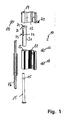
- a hinge fitting 10 is shown in an exploded view.
- the hinge fitting 10 comprises a hinge-side hinge body 11 and a wing-side hinge body 12. Both hinge bodies 11, 12 have a passage opening 13, 14 for receiving a bearing pin 15.
- the attachment of the enclosure-side hinge body 11 via a terminal block 16 which is connected via fastening means 17, 18 with the hinge body 11, in particular screwed.
- the attachment of the wing-side hinge body 12 via the attachment means 19.
- a bushing 20 is inserted into the through hole 13 of the enclosure-side hinge body 11.
- the bushing 20 receives the bearing pin 15.
- it has a passage opening 21.
- the assembly is done as follows:
- the hinge body 11,12 are attached to the fixed frame or sash. Subsequently, the sleeve 20 is inserted in the correct position in the passage opening 13. In this case, the edge 22 abuts the top of the hinge body 11. Subsequently, the bearing pin 15 is inserted from below into the socket 20.
- the bushing 20 has a holding device 23, which comprises a web 24 fastened on both sides. The web has a pointing into the interior of the bushing projection which presses either against the shaft of the bearing pin 15 or engages in the annular groove 25. As a result, the bearing pin 15 is held captive in the socket 20. Subsequently, the wing-side hinge body 12 is positioned over the surround-side hinge body 11 and the bearing pin 15 is inserted from below into the through-hole 21. This is then fixed by the screw 40, which engages in the annular groove 25.
- the upper end of the through hole 21 is arranged eccentrically. This is because the longitudinal axis of the passage opening 21 is inclined relative to the longitudinal axis of the bushing 20. As a result, an inclination of the bearing pin 15 is effected.
- FIG. 2 shows the hinge fitting 10 in the assembled state.
- the bearing pin 15 is inclined relative to the vertical.
- the bushing 20, which is arranged in the hinge-side hinge body 11 has an inner lateral surface 30 whose longitudinal axis is inclined with respect to the longitudinal axis of the outer lateral surface 31.
- the longitudinal axis of the outer lateral surface 31 is vertically aligned.
- the hinge body 12 is also aligned obliquely due to the inclination of the bearing pin 15 and is not aligned with the enclosure-side hinge body 11.
- the hinge body 12 By the sash weight acting in the direction of arrow 32, the hinge body 12 is also moved in the direction of arrow 32, so that the gap is reduced at the point 33 and the hinge body 11,12 are aligned with each other. This means that the bearing pin 15 is aligned against its load deformation.
- FIG. 3 shows that with the circle III in the FIG. 2 marked detail in an enlarged view.
- an inwardly directed projection 35 which is arranged on a bridge 24 fixed on both sides of the bush 20.
- the web 24 and the projection 35 can be deflected by the bearing pin, so that by locking projection 35 in the annular groove 25 of the bearing pin 15 is held captive inside the sleeve 20.
- FIG. 4 is a sectional view taken along the line IV-IV of FIG. 2 shown.
- the socket 20 has an encoding 36, which is formed as a radial projection and engages in a corresponding notch or groove 37 of the enclosure-side hinge body 11. As a result, the correct position installation of the sleeve 20 is ensured.
Landscapes
- Engineering & Computer Science (AREA)
- Mechanical Engineering (AREA)
- Hinges (AREA)
- Underground Structures, Protecting, Testing And Restoring Foundations (AREA)
- Pivots And Pivotal Connections (AREA)
- Wing Frames And Configurations (AREA)
- Lock And Its Accessories (AREA)
Priority Applications (6)
| Application Number | Priority Date | Filing Date | Title |
|---|---|---|---|
| AT07015661T ATE445071T1 (de) | 2007-08-09 | 2007-08-09 | Scharnierbeschlag eines fensters, einer tür oder dgl. mit schrägem scharnierstift |
| PL07015661T PL2025845T3 (pl) | 2007-08-09 | 2007-08-09 | Okucie zawiasowe okna, drzwi lub tym podobnych, z ukośnym trzpieniem zawiasy |
| ES07015661T ES2333552T3 (es) | 2007-08-09 | 2007-08-09 | Herraje de bisagra para una ventana, una puerta o similares, con un casquillo oblicuo. |
| EP07015661A EP2025845B1 (de) | 2007-08-09 | 2007-08-09 | Scharnierbeschlag eines Fensters, einer Tür oder dgl. mit schrägem Scharnierstift |
| DE502007001696T DE502007001696D1 (de) | 2007-08-09 | 2007-08-09 | Scharnierbeschlag eines Fensters, einer Tür oder dgl. mit schrägem Scharnierstift |
| CN2008100992393A CN101363302B (zh) | 2007-08-09 | 2008-05-15 | 窗、门或类似物的具有倾斜衬套的合页配件 |
Applications Claiming Priority (1)
| Application Number | Priority Date | Filing Date | Title |
|---|---|---|---|
| EP07015661A EP2025845B1 (de) | 2007-08-09 | 2007-08-09 | Scharnierbeschlag eines Fensters, einer Tür oder dgl. mit schrägem Scharnierstift |
Publications (2)
| Publication Number | Publication Date |
|---|---|
| EP2025845A1 EP2025845A1 (de) | 2009-02-18 |
| EP2025845B1 true EP2025845B1 (de) | 2009-10-07 |
Family
ID=38803273
Family Applications (1)
| Application Number | Title | Priority Date | Filing Date |
|---|---|---|---|
| EP07015661A Active EP2025845B1 (de) | 2007-08-09 | 2007-08-09 | Scharnierbeschlag eines Fensters, einer Tür oder dgl. mit schrägem Scharnierstift |
Country Status (6)
| Country | Link |
|---|---|
| EP (1) | EP2025845B1 (pl) |
| CN (1) | CN101363302B (pl) |
| AT (1) | ATE445071T1 (pl) |
| DE (1) | DE502007001696D1 (pl) |
| ES (1) | ES2333552T3 (pl) |
| PL (1) | PL2025845T3 (pl) |
Families Citing this family (2)
| Publication number | Priority date | Publication date | Assignee | Title |
|---|---|---|---|---|
| DE202013103109U1 (de) * | 2013-07-12 | 2014-10-13 | Dr. Hahn Gmbh & Co. Kg | Bandlappen eines Bandes |
| DE102019106099B4 (de) * | 2019-03-11 | 2022-11-10 | Gerd Lämmermann | Insektenschutztür |
Family Cites Families (4)
| Publication number | Priority date | Publication date | Assignee | Title |
|---|---|---|---|---|
| AT378403B (de) * | 1981-12-21 | 1985-08-12 | Mayer & Co Riegel Beschlag | Einstellbares ecklager fuer einen schwenk-kippfl¨gel eines fensters oder einer tuer |
| DE8911831U1 (de) * | 1989-10-04 | 1990-02-08 | Siegenia-Frank Kg, 5900 Siegen | Scharnier für Fenster, Türen od.dgl. |
| DE29602522U1 (de) * | 1996-02-14 | 1996-05-09 | Siegenia-Frank Kg, 57074 Siegen | Eckscharnier, insbesondere Drehkipp-Ecklager für Fenster und Türen o.dgl. |
| EP1772578A1 (en) * | 2005-10-04 | 2007-04-11 | Metalglas S.r.l. | Hinge for glass door |
-
2007
- 2007-08-09 EP EP07015661A patent/EP2025845B1/de active Active
- 2007-08-09 PL PL07015661T patent/PL2025845T3/pl unknown
- 2007-08-09 AT AT07015661T patent/ATE445071T1/de active
- 2007-08-09 ES ES07015661T patent/ES2333552T3/es active Active
- 2007-08-09 DE DE502007001696T patent/DE502007001696D1/de active Active
-
2008
- 2008-05-15 CN CN2008100992393A patent/CN101363302B/zh active Active
Also Published As
| Publication number | Publication date |
|---|---|
| CN101363302B (zh) | 2012-07-25 |
| DE502007001696D1 (de) | 2009-11-19 |
| PL2025845T3 (pl) | 2010-03-31 |
| ATE445071T1 (de) | 2009-10-15 |
| EP2025845A1 (de) | 2009-02-18 |
| ES2333552T3 (es) | 2010-02-23 |
| CN101363302A (zh) | 2009-02-11 |
Similar Documents
| Publication | Publication Date | Title |
|---|---|---|
| EP1332264A1 (de) | Büchse für die befestigung eines beschlagteils an einem mit einem vorgesetzten profilteil versehenen hohlprofil | |
| EP0947654B1 (de) | Verschwindscharnier | |
| EP2169163B1 (de) | Höhenverstellbares Band | |
| EP3511499A1 (de) | Vorrichtung zur schwenkbaren befestigung eines türflügels an einer türzarge | |
| EP2025845B1 (de) | Scharnierbeschlag eines Fensters, einer Tür oder dgl. mit schrägem Scharnierstift | |
| EP1223274B1 (de) | Büchse für die Befestigung eines Beschlagteils an einem Hohlprofil | |
| EP1215357B1 (de) | Bandanordnung für Türen, Fenster und dergleichen | |
| DE10105264C1 (de) | Scharnierband für Türen und Fenster | |
| EP4105416B1 (de) | Feststellvorrichtung für beidseitig angeschlagene tür | |
| EP1936083B1 (de) | Stützvorrichtung für ein Scharnier einer Schließeinheit | |
| EP2038499A1 (de) | Bandanordnung für türen, fenster oder dergleichen | |
| DE202014100182U1 (de) | Türbeschlag | |
| EP1915498B1 (de) | Profilbandsystem | |
| EP1922467B1 (de) | Band für türen, fenster oder dergleichen | |
| EP1215356B1 (de) | Bandanordnung für Türen, Fenster und dergleichen | |
| EP1653030B1 (de) | Scharnier mit wenigstens zwei Scharnierteilen zur Anordnung in Zusammenwirken mit einem Trag- und Aufnahmeelement | |
| EP4105420B1 (de) | Band fuer eine tuer oder ein fenster | |
| EP2228509B1 (de) | Ausstellvorrichtung einer Verschlusseinrichtung zum mindestens teilweisen Verschließen einer Raumöffnung | |
| EP1898033B1 (de) | Beschlagsystem | |
| DE29804967U1 (de) | Tür- oder Fensterband | |
| DE102006025215B4 (de) | Kraftfahrzeugscharnier für Türen und Klappen | |
| EP3029243A1 (de) | Gegenlageranordnung eines scharniers eines fensters, einer tür oder dergleichen | |
| DE29808660U1 (de) | Tür- oder Fensterdrehband | |
| EP1697609A1 (de) | Bodentürschliesser | |
| DE202007011073U1 (de) | Befestigung für ein Scharnierband |
Legal Events
| Date | Code | Title | Description |
|---|---|---|---|
| PUAI | Public reference made under article 153(3) epc to a published international application that has entered the european phase |
Free format text: ORIGINAL CODE: 0009012 |
|
| 17P | Request for examination filed |
Effective date: 20080315 |
|
| AK | Designated contracting states |
Kind code of ref document: A1 Designated state(s): AT BE BG CH CY CZ DE DK EE ES FI FR GB GR HU IE IS IT LI LT LU LV MC MT NL PL PT RO SE SI SK TR |
|
| AX | Request for extension of the european patent |
Extension state: AL BA HR MK RS |
|
| GRAP | Despatch of communication of intention to grant a patent |
Free format text: ORIGINAL CODE: EPIDOSNIGR1 |
|
| GRAS | Grant fee paid |
Free format text: ORIGINAL CODE: EPIDOSNIGR3 |
|
| GRAA | (expected) grant |
Free format text: ORIGINAL CODE: 0009210 |
|
| AK | Designated contracting states |
Kind code of ref document: B1 Designated state(s): AT BE BG CH CY CZ DE DK EE ES FI FR GB GR HU IE IS IT LI LT LU LV MC MT NL PL PT RO SE SI SK TR |
|
| REG | Reference to a national code |
Ref country code: GB Ref legal event code: FG4D Free format text: NOT ENGLISH |
|
| REG | Reference to a national code |
Ref country code: CH Ref legal event code: EP |
|
| AKX | Designation fees paid |
Designated state(s): AT BE BG CH CY CZ DE DK EE ES FI FR GB GR HU IE IS IT LI LT LU LV MC MT NL PL PT RO SE SI SK TR |
|
| REG | Reference to a national code |
Ref country code: IE Ref legal event code: FG4D |
|
| REF | Corresponds to: |
Ref document number: 502007001696 Country of ref document: DE Date of ref document: 20091119 Kind code of ref document: P |
|
| REG | Reference to a national code |
Ref country code: GR Ref legal event code: EP Ref document number: 20090403169 Country of ref document: GR |
|
| PG25 | Lapsed in a contracting state [announced via postgrant information from national office to epo] |
Ref country code: SI Free format text: LAPSE BECAUSE OF FAILURE TO SUBMIT A TRANSLATION OF THE DESCRIPTION OR TO PAY THE FEE WITHIN THE PRESCRIBED TIME-LIMIT Effective date: 20091007 |
|
| NLV1 | Nl: lapsed or annulled due to failure to fulfill the requirements of art. 29p and 29m of the patents act | ||
| LTIE | Lt: invalidation of european patent or patent extension |
Effective date: 20091007 |
|
| REG | Reference to a national code |
Ref country code: PL Ref legal event code: T3 |
|
| PG25 | Lapsed in a contracting state [announced via postgrant information from national office to epo] |
Ref country code: IS Free format text: LAPSE BECAUSE OF FAILURE TO SUBMIT A TRANSLATION OF THE DESCRIPTION OR TO PAY THE FEE WITHIN THE PRESCRIBED TIME-LIMIT Effective date: 20100207 Ref country code: FI Free format text: LAPSE BECAUSE OF FAILURE TO SUBMIT A TRANSLATION OF THE DESCRIPTION OR TO PAY THE FEE WITHIN THE PRESCRIBED TIME-LIMIT Effective date: 20091007 Ref country code: SE Free format text: LAPSE BECAUSE OF FAILURE TO SUBMIT A TRANSLATION OF THE DESCRIPTION OR TO PAY THE FEE WITHIN THE PRESCRIBED TIME-LIMIT Effective date: 20091007 Ref country code: PT Free format text: LAPSE BECAUSE OF FAILURE TO SUBMIT A TRANSLATION OF THE DESCRIPTION OR TO PAY THE FEE WITHIN THE PRESCRIBED TIME-LIMIT Effective date: 20100208 Ref country code: LT Free format text: LAPSE BECAUSE OF FAILURE TO SUBMIT A TRANSLATION OF THE DESCRIPTION OR TO PAY THE FEE WITHIN THE PRESCRIBED TIME-LIMIT Effective date: 20091007 |
|
| REG | Reference to a national code |
Ref country code: IE Ref legal event code: FD4D |
|
| PG25 | Lapsed in a contracting state [announced via postgrant information from national office to epo] |
Ref country code: LV Free format text: LAPSE BECAUSE OF FAILURE TO SUBMIT A TRANSLATION OF THE DESCRIPTION OR TO PAY THE FEE WITHIN THE PRESCRIBED TIME-LIMIT Effective date: 20091007 |
|
| PG25 | Lapsed in a contracting state [announced via postgrant information from national office to epo] |
Ref country code: EE Free format text: LAPSE BECAUSE OF FAILURE TO SUBMIT A TRANSLATION OF THE DESCRIPTION OR TO PAY THE FEE WITHIN THE PRESCRIBED TIME-LIMIT Effective date: 20091007 Ref country code: DK Free format text: LAPSE BECAUSE OF FAILURE TO SUBMIT A TRANSLATION OF THE DESCRIPTION OR TO PAY THE FEE WITHIN THE PRESCRIBED TIME-LIMIT Effective date: 20091007 Ref country code: BG Free format text: LAPSE BECAUSE OF FAILURE TO SUBMIT A TRANSLATION OF THE DESCRIPTION OR TO PAY THE FEE WITHIN THE PRESCRIBED TIME-LIMIT Effective date: 20100107 Ref country code: RO Free format text: LAPSE BECAUSE OF FAILURE TO SUBMIT A TRANSLATION OF THE DESCRIPTION OR TO PAY THE FEE WITHIN THE PRESCRIBED TIME-LIMIT Effective date: 20091007 Ref country code: IE Free format text: LAPSE BECAUSE OF FAILURE TO SUBMIT A TRANSLATION OF THE DESCRIPTION OR TO PAY THE FEE WITHIN THE PRESCRIBED TIME-LIMIT Effective date: 20091007 Ref country code: NL Free format text: LAPSE BECAUSE OF FAILURE TO SUBMIT A TRANSLATION OF THE DESCRIPTION OR TO PAY THE FEE WITHIN THE PRESCRIBED TIME-LIMIT Effective date: 20091007 |
|
| PLBE | No opposition filed within time limit |
Free format text: ORIGINAL CODE: 0009261 |
|
| STAA | Information on the status of an ep patent application or granted ep patent |
Free format text: STATUS: NO OPPOSITION FILED WITHIN TIME LIMIT |
|
| PG25 | Lapsed in a contracting state [announced via postgrant information from national office to epo] |
Ref country code: SK Free format text: LAPSE BECAUSE OF FAILURE TO SUBMIT A TRANSLATION OF THE DESCRIPTION OR TO PAY THE FEE WITHIN THE PRESCRIBED TIME-LIMIT Effective date: 20091007 Ref country code: CZ Free format text: LAPSE BECAUSE OF FAILURE TO SUBMIT A TRANSLATION OF THE DESCRIPTION OR TO PAY THE FEE WITHIN THE PRESCRIBED TIME-LIMIT Effective date: 20091007 |
|
| 26N | No opposition filed |
Effective date: 20100708 |
|
| PG25 | Lapsed in a contracting state [announced via postgrant information from national office to epo] |
Ref country code: MC Free format text: LAPSE BECAUSE OF NON-PAYMENT OF DUE FEES Effective date: 20100831 |
|
| PG25 | Lapsed in a contracting state [announced via postgrant information from national office to epo] |
Ref country code: MT Free format text: LAPSE BECAUSE OF FAILURE TO SUBMIT A TRANSLATION OF THE DESCRIPTION OR TO PAY THE FEE WITHIN THE PRESCRIBED TIME-LIMIT Effective date: 20091007 |
|
| REG | Reference to a national code |
Ref country code: CH Ref legal event code: PL |
|
| GBPC | Gb: european patent ceased through non-payment of renewal fee |
Effective date: 20110809 |
|
| PG25 | Lapsed in a contracting state [announced via postgrant information from national office to epo] |
Ref country code: CH Free format text: LAPSE BECAUSE OF NON-PAYMENT OF DUE FEES Effective date: 20110831 Ref country code: LI Free format text: LAPSE BECAUSE OF NON-PAYMENT OF DUE FEES Effective date: 20110831 |
|
| PG25 | Lapsed in a contracting state [announced via postgrant information from national office to epo] |
Ref country code: CY Free format text: LAPSE BECAUSE OF FAILURE TO SUBMIT A TRANSLATION OF THE DESCRIPTION OR TO PAY THE FEE WITHIN THE PRESCRIBED TIME-LIMIT Effective date: 20091007 Ref country code: GB Free format text: LAPSE BECAUSE OF NON-PAYMENT OF DUE FEES Effective date: 20110809 |
|
| PG25 | Lapsed in a contracting state [announced via postgrant information from national office to epo] |
Ref country code: LU Free format text: LAPSE BECAUSE OF NON-PAYMENT OF DUE FEES Effective date: 20100809 Ref country code: HU Free format text: LAPSE BECAUSE OF FAILURE TO SUBMIT A TRANSLATION OF THE DESCRIPTION OR TO PAY THE FEE WITHIN THE PRESCRIBED TIME-LIMIT Effective date: 20100408 |
|
| REG | Reference to a national code |
Ref country code: FR Ref legal event code: PLFP Year of fee payment: 10 |
|
| REG | Reference to a national code |
Ref country code: FR Ref legal event code: PLFP Year of fee payment: 11 |
|
| REG | Reference to a national code |
Ref country code: FR Ref legal event code: PLFP Year of fee payment: 12 |
|
| PG25 | Lapsed in a contracting state [announced via postgrant information from national office to epo] |
Ref country code: GR Free format text: LAPSE BECAUSE OF NON-PAYMENT OF DUE FEES Effective date: 20190307 |
|
| PGFP | Annual fee paid to national office [announced via postgrant information from national office to epo] |
Ref country code: AT Payment date: 20200819 Year of fee payment: 14 |
|
| REG | Reference to a national code |
Ref country code: AT Ref legal event code: MM01 Ref document number: 445071 Country of ref document: AT Kind code of ref document: T Effective date: 20210809 |
|
| PG25 | Lapsed in a contracting state [announced via postgrant information from national office to epo] |
Ref country code: AT Free format text: LAPSE BECAUSE OF NON-PAYMENT OF DUE FEES Effective date: 20210809 |
|
| PGFP | Annual fee paid to national office [announced via postgrant information from national office to epo] |
Ref country code: DE Payment date: 20240819 Year of fee payment: 18 |
|
| PGFP | Annual fee paid to national office [announced via postgrant information from national office to epo] |
Ref country code: BE Payment date: 20240820 Year of fee payment: 18 |
|
| PGFP | Annual fee paid to national office [announced via postgrant information from national office to epo] |
Ref country code: FR Payment date: 20240823 Year of fee payment: 18 |
|
| PGFP | Annual fee paid to national office [announced via postgrant information from national office to epo] |
Ref country code: ES Payment date: 20240918 Year of fee payment: 18 |
|
| PGFP | Annual fee paid to national office [announced via postgrant information from national office to epo] |
Ref country code: PL Payment date: 20240729 Year of fee payment: 18 |
|
| PGFP | Annual fee paid to national office [announced via postgrant information from national office to epo] |
Ref country code: IT Payment date: 20240830 Year of fee payment: 18 |
|
| PGFP | Annual fee paid to national office [announced via postgrant information from national office to epo] |
Ref country code: TR Payment date: 20240730 Year of fee payment: 18 |
|
| REG | Reference to a national code |
Ref country code: DE Ref legal event code: R119 Ref document number: 502007001696 Country of ref document: DE |