EP2025439A1 - Ausrichten eines Maschinenwerkzeugs mit einem Zielort auf einer Struktur - Google Patents
Ausrichten eines Maschinenwerkzeugs mit einem Zielort auf einer Struktur Download PDFInfo
- Publication number
- EP2025439A1 EP2025439A1 EP08161685A EP08161685A EP2025439A1 EP 2025439 A1 EP2025439 A1 EP 2025439A1 EP 08161685 A EP08161685 A EP 08161685A EP 08161685 A EP08161685 A EP 08161685A EP 2025439 A1 EP2025439 A1 EP 2025439A1
- Authority
- EP
- European Patent Office
- Prior art keywords
- plate
- nosepiece
- bushing
- collet
- housing
- Prior art date
- Legal status (The legal status is an assumption and is not a legal conclusion. Google has not performed a legal analysis and makes no representation as to the accuracy of the status listed.)
- Granted
Links
- 238000000034 method Methods 0.000 claims description 27
- 238000003754 machining Methods 0.000 claims description 11
- 238000013459 approach Methods 0.000 claims description 7
- 238000005553 drilling Methods 0.000 description 20
- 238000004519 manufacturing process Methods 0.000 description 10
- 238000005520 cutting process Methods 0.000 description 7
- 238000010586 diagram Methods 0.000 description 6
- 239000000463 material Substances 0.000 description 4
- 230000008569 process Effects 0.000 description 4
- 229910001220 stainless steel Inorganic materials 0.000 description 4
- 229910001315 Tool steel Inorganic materials 0.000 description 3
- 239000002131 composite material Substances 0.000 description 2
- 238000010276 construction Methods 0.000 description 2
- 238000013461 design Methods 0.000 description 2
- 238000012423 maintenance Methods 0.000 description 2
- 230000004048 modification Effects 0.000 description 2
- 238000012986 modification Methods 0.000 description 2
- 239000007787 solid Substances 0.000 description 2
- 239000010935 stainless steel Substances 0.000 description 2
- 229920000049 Carbon (fiber) Polymers 0.000 description 1
- 241000587161 Gomphocarpus Species 0.000 description 1
- 229910000831 Steel Inorganic materials 0.000 description 1
- RTAQQCXQSZGOHL-UHFFFAOYSA-N Titanium Chemical group [Ti] RTAQQCXQSZGOHL-UHFFFAOYSA-N 0.000 description 1
- DHKHKXVYLBGOIT-UHFFFAOYSA-N acetaldehyde Diethyl Acetal Natural products CCOC(C)OCC DHKHKXVYLBGOIT-UHFFFAOYSA-N 0.000 description 1
- 230000009471 action Effects 0.000 description 1
- 229910052782 aluminium Inorganic materials 0.000 description 1
- XAGFODPZIPBFFR-UHFFFAOYSA-N aluminium Chemical compound [Al] XAGFODPZIPBFFR-UHFFFAOYSA-N 0.000 description 1
- 239000004917 carbon fiber Substances 0.000 description 1
- 239000004918 carbon fiber reinforced polymer Substances 0.000 description 1
- 229920001577 copolymer Polymers 0.000 description 1
- 230000032798 delamination Effects 0.000 description 1
- 230000001419 dependent effect Effects 0.000 description 1
- 238000006073 displacement reaction Methods 0.000 description 1
- 239000013013 elastic material Substances 0.000 description 1
- 230000007613 environmental effect Effects 0.000 description 1
- 238000009434 installation Methods 0.000 description 1
- 230000010354 integration Effects 0.000 description 1
- 230000007246 mechanism Effects 0.000 description 1
- 229910052751 metal Inorganic materials 0.000 description 1
- 239000002184 metal Substances 0.000 description 1
- 150000002739 metals Chemical class 0.000 description 1
- VNWKTOKETHGBQD-UHFFFAOYSA-N methane Chemical compound C VNWKTOKETHGBQD-UHFFFAOYSA-N 0.000 description 1
- 230000008520 organization Effects 0.000 description 1
- 238000012545 processing Methods 0.000 description 1
- 238000009419 refurbishment Methods 0.000 description 1
- 239000010959 steel Substances 0.000 description 1
- XLYOFNOQVPJJNP-UHFFFAOYSA-N water Substances O XLYOFNOQVPJJNP-UHFFFAOYSA-N 0.000 description 1
Images


Classifications
-
- B—PERFORMING OPERATIONS; TRANSPORTING
- B23—MACHINE TOOLS; METAL-WORKING NOT OTHERWISE PROVIDED FOR
- B23B—TURNING; BORING
- B23B49/00—Measuring or gauging equipment on boring machines for positioning or guiding the drill; Devices for indicating failure of drills during boring; Centering devices for holes to be bored
- B23B49/02—Boring templates or bushings
- B23B49/023—Bushings and their connection to the template
-
- B—PERFORMING OPERATIONS; TRANSPORTING
- B23—MACHINE TOOLS; METAL-WORKING NOT OTHERWISE PROVIDED FOR
- B23B—TURNING; BORING
- B23B2215/00—Details of workpieces
- B23B2215/04—Aircraft components
-
- Y—GENERAL TAGGING OF NEW TECHNOLOGICAL DEVELOPMENTS; GENERAL TAGGING OF CROSS-SECTIONAL TECHNOLOGIES SPANNING OVER SEVERAL SECTIONS OF THE IPC; TECHNICAL SUBJECTS COVERED BY FORMER USPC CROSS-REFERENCE ART COLLECTIONS [XRACs] AND DIGESTS
- Y10—TECHNICAL SUBJECTS COVERED BY FORMER USPC
- Y10T—TECHNICAL SUBJECTS COVERED BY FORMER US CLASSIFICATION
- Y10T279/00—Chucks or sockets
- Y10T279/17—Socket type
- Y10T279/17291—Resilient split socket
- Y10T279/17316—Unitary
- Y10T279/17324—Split at one end only
- Y10T279/17341—Cam actuator
-
- Y—GENERAL TAGGING OF NEW TECHNOLOGICAL DEVELOPMENTS; GENERAL TAGGING OF CROSS-SECTIONAL TECHNOLOGIES SPANNING OVER SEVERAL SECTIONS OF THE IPC; TECHNICAL SUBJECTS COVERED BY FORMER USPC CROSS-REFERENCE ART COLLECTIONS [XRACs] AND DIGESTS
- Y10—TECHNICAL SUBJECTS COVERED BY FORMER USPC
- Y10T—TECHNICAL SUBJECTS COVERED BY FORMER US CLASSIFICATION
- Y10T408/00—Cutting by use of rotating axially moving tool
- Y10T408/03—Processes
-
- Y—GENERAL TAGGING OF NEW TECHNOLOGICAL DEVELOPMENTS; GENERAL TAGGING OF CROSS-SECTIONAL TECHNOLOGIES SPANNING OVER SEVERAL SECTIONS OF THE IPC; TECHNICAL SUBJECTS COVERED BY FORMER USPC CROSS-REFERENCE ART COLLECTIONS [XRACs] AND DIGESTS
- Y10—TECHNICAL SUBJECTS COVERED BY FORMER USPC
- Y10T—TECHNICAL SUBJECTS COVERED BY FORMER US CLASSIFICATION
- Y10T408/00—Cutting by use of rotating axially moving tool
- Y10T408/55—Cutting by use of rotating axially moving tool with work-engaging structure other than Tool or tool-support
- Y10T408/561—Having tool-opposing, work-engaging surface
- Y10T408/5623—Having tool-opposing, work-engaging surface with presser foot
- Y10T408/56245—Having tool-opposing, work-engaging surface with presser foot including tool-guide [or bushing]
-
- Y—GENERAL TAGGING OF NEW TECHNOLOGICAL DEVELOPMENTS; GENERAL TAGGING OF CROSS-SECTIONAL TECHNOLOGIES SPANNING OVER SEVERAL SECTIONS OF THE IPC; TECHNICAL SUBJECTS COVERED BY FORMER USPC CROSS-REFERENCE ART COLLECTIONS [XRACs] AND DIGESTS
- Y10—TECHNICAL SUBJECTS COVERED BY FORMER USPC
- Y10T—TECHNICAL SUBJECTS COVERED BY FORMER US CLASSIFICATION
- Y10T408/00—Cutting by use of rotating axially moving tool
- Y10T408/55—Cutting by use of rotating axially moving tool with work-engaging structure other than Tool or tool-support
- Y10T408/564—Movable relative to Tool along tool-axis
-
- Y—GENERAL TAGGING OF NEW TECHNOLOGICAL DEVELOPMENTS; GENERAL TAGGING OF CROSS-SECTIONAL TECHNOLOGIES SPANNING OVER SEVERAL SECTIONS OF THE IPC; TECHNICAL SUBJECTS COVERED BY FORMER USPC CROSS-REFERENCE ART COLLECTIONS [XRACs] AND DIGESTS
- Y10—TECHNICAL SUBJECTS COVERED BY FORMER USPC
- Y10T—TECHNICAL SUBJECTS COVERED BY FORMER US CLASSIFICATION
- Y10T408/00—Cutting by use of rotating axially moving tool
- Y10T408/55—Cutting by use of rotating axially moving tool with work-engaging structure other than Tool or tool-support
- Y10T408/567—Adjustable, tool-guiding jig
- Y10T408/568—Guide bushing
-
- Y—GENERAL TAGGING OF NEW TECHNOLOGICAL DEVELOPMENTS; GENERAL TAGGING OF CROSS-SECTIONAL TECHNOLOGIES SPANNING OVER SEVERAL SECTIONS OF THE IPC; TECHNICAL SUBJECTS COVERED BY FORMER USPC CROSS-REFERENCE ART COLLECTIONS [XRACs] AND DIGESTS
- Y10—TECHNICAL SUBJECTS COVERED BY FORMER USPC
- Y10T—TECHNICAL SUBJECTS COVERED BY FORMER US CLASSIFICATION
- Y10T408/00—Cutting by use of rotating axially moving tool
- Y10T408/55—Cutting by use of rotating axially moving tool with work-engaging structure other than Tool or tool-support
- Y10T408/569—Bushing
-
- Y—GENERAL TAGGING OF NEW TECHNOLOGICAL DEVELOPMENTS; GENERAL TAGGING OF CROSS-SECTIONAL TECHNOLOGIES SPANNING OVER SEVERAL SECTIONS OF THE IPC; TECHNICAL SUBJECTS COVERED BY FORMER USPC CROSS-REFERENCE ART COLLECTIONS [XRACs] AND DIGESTS
- Y10—TECHNICAL SUBJECTS COVERED BY FORMER USPC
- Y10T—TECHNICAL SUBJECTS COVERED BY FORMER US CLASSIFICATION
- Y10T408/00—Cutting by use of rotating axially moving tool
- Y10T408/96—Miscellaneous
- Y10T408/98—Drill guide
-
- Y—GENERAL TAGGING OF NEW TECHNOLOGICAL DEVELOPMENTS; GENERAL TAGGING OF CROSS-SECTIONAL TECHNOLOGIES SPANNING OVER SEVERAL SECTIONS OF THE IPC; TECHNICAL SUBJECTS COVERED BY FORMER USPC CROSS-REFERENCE ART COLLECTIONS [XRACs] AND DIGESTS
- Y10—TECHNICAL SUBJECTS COVERED BY FORMER USPC
- Y10T—TECHNICAL SUBJECTS COVERED BY FORMER US CLASSIFICATION
- Y10T409/00—Gear cutting, milling, or planing
- Y10T409/30—Milling
- Y10T409/303752—Process
-
- Y—GENERAL TAGGING OF NEW TECHNOLOGICAL DEVELOPMENTS; GENERAL TAGGING OF CROSS-SECTIONAL TECHNOLOGIES SPANNING OVER SEVERAL SECTIONS OF THE IPC; TECHNICAL SUBJECTS COVERED BY FORMER USPC CROSS-REFERENCE ART COLLECTIONS [XRACs] AND DIGESTS
- Y10—TECHNICAL SUBJECTS COVERED BY FORMER USPC
- Y10T—TECHNICAL SUBJECTS COVERED BY FORMER US CLASSIFICATION
- Y10T409/00—Gear cutting, milling, or planing
- Y10T409/30—Milling
- Y10T409/306664—Milling including means to infeed rotary cutter toward work
- Y10T409/30756—Machining arcuate surface
- Y10T409/307616—Machining arcuate surface with means to move cutter eccentrically
-
- Y—GENERAL TAGGING OF NEW TECHNOLOGICAL DEVELOPMENTS; GENERAL TAGGING OF CROSS-SECTIONAL TECHNOLOGIES SPANNING OVER SEVERAL SECTIONS OF THE IPC; TECHNICAL SUBJECTS COVERED BY FORMER USPC CROSS-REFERENCE ART COLLECTIONS [XRACs] AND DIGESTS
- Y10—TECHNICAL SUBJECTS COVERED BY FORMER USPC
- Y10T—TECHNICAL SUBJECTS COVERED BY FORMER US CLASSIFICATION
- Y10T409/00—Gear cutting, milling, or planing
- Y10T409/30—Milling
- Y10T409/309352—Cutter spindle or spindle support
- Y10T409/309408—Cutter spindle or spindle support with cutter holder
Definitions
- the present disclosure relates generally to machine tooling for the construction and assembly of structures and more particularly (but not exclusively) to aligning a machine tool such as a drill or cutting tool with a target location in a structure.
- two or more parts may be spliced together to form an airframe section.
- One part typically is overlaid onto another, and holes may be drilled through the aligned parts to accommodate fasteners.
- Drilling locations in the parts are typically selected in accordance with nominal design specifications. In some splicing applications, drill jigs may be used to guide a drilling tool to the nominal drilling locations.
- the present disclosure in one configuration, is directed to an apparatus for aligning a machine tool with a target location on a structure.
- the apparatus includes a machine plate positionable on the structure.
- the plate has a plate bushing that provides a hole through the machine plate.
- the apparatus also includes a nosepiece for guiding a distal end of the tool through the plate bushing to the target location.
- the nosepiece has a collet configured to be moved at least partly through and sideward in the plate bushing to center the nosepiece on an element projecting from the structure at the target location.
- the nosepiece is configured for attachment to the plate bushing to establish a predefined approach angle of the tool relative to the projecting element.
- the disclosure is directed to a machine assembly including a machine tool and an apparatus for aligning a distal end of the machine tool with a target location on a structure.
- the apparatus includes a machine plate positionable on the structure and having one or more plate bushings each providing a hole through the machine plate.
- the apparatus also includes a nosepiece for guiding the tool distal end through the plate bushing to the target location when the plate bushing is placed over the target location.
- the nosepiece has a housing and a collet attached to and extending distally from the housing.
- the collet has a distal end configured to pass through the plate bushing.
- the collet is further configured to be moved radially in the plate bushing to center the nosepiece over an element projecting from the structure at the target location.
- the housing is configured for attachment to the plate bushing to establish normality of the tool relative to the projecting element.
- the disclosure is directed to a method of aligning a machine tool with a target location on a structure.
- a distal end of the machine tool is inserted into a nosepiece for guiding a distal end of the tool.
- the nosepiece has a housing and a collet attached to and extending distally from the housing.
- the method includes inserting a distal end of the collet through a plate bushing in a machine plate positioned over an element projecting from the structure at the target location.
- the collet is moved radially in the plate bushing to center the collet distal end over the element projecting from the structure.
- the method includes affixing the centered collet distal end to the projecting element, and affixing a distal end of the housing to the plate bushing.
- the disclosure is directed to a machine plate for use with a machine tool.
- the machine plate has a body including at least one plate bushing having a hole positionable relative to a target location on a structure.
- the plate bushing includes a rim graspable by a nosepiece through which the machine tool is operable.
- the plate bushing is configured to allow passage therethrough of a distal end of a collet attached to the nosepiece.
- the plate bushing is further configured to allow radial movement of the collet therein for centering of the collet over an element projecting from the structure at the target location.
- the plate bushing is further configured to establish a predefined angle of approach by the machine tool relative to the projecting element when the nosepiece has grasped the rim of the plate bushing.
- a machine assembly comprising: a machine tool; and an apparatus for aligning a distal end of the machine tool with a target location on a structure, the apparatus including a machine plate positionable on the structure and having one or more plate bushings each providing a hole through the machine plate, and a nosepiece for guiding the tool distal end through the plate bushing to the target location when the plate bushing is placed over the target location, the nosepiece having a housing and a collet attached to and extending distally from the housing; the collet having a distal end configured to pass through the plate bushing; the collet further configured to be moved radially in the plate bushing to center the nosepiece over an element projecting from the structure at the target location; the housing configured for attachment to the plate bushing to establish normality of the tool relative to the projecting element.
- the housing may have a distal end configured to be fitted over the plate bushing.
- the nosepiece may further comprise a clamp operable to clamp the collet onto the projecting element.
- the nosepiece may further comprise a clamp and a piston operable to push the clamp at least partially through the housing to clamp the collet onto the projecting element and the housing onto the plate bushing.
- the piston may be attached to the clamp.
- the plate bushing may comprise a proximal rim configured to mate with a distal end of the housing.
- the machine assembly may further comprise a machining module affixed to the apparatus and operable to actuate the machine tool.
- the machining module may include an orbital drill unit.
- a machine plate for use with a machine tool, the machine plate comprising a body including at least one plate bushing having a hole positionable relative to a target location on a structure; the plate bushing comprising a rim graspable by a nosepiece through which the machine tool is operable, the plate bushing configured to allow passage therethrough of a distal end of a collet attached to the nosepiece, the plate bushing further configured to allow radial movement of the collet therein for centering of the collet over an element projecting from the structure at the target location; the plate bushing further configured to establish a predefined angle of approach by the machine tool relative to the projecting element when the nosepiece has grasped the rim of the plate bushing.
- the plate bushing may be configured to allow the collet to be centered over a bushing in a hole in the structure.
- the rim of the plate bushing may comprise a plurality of lobes configured to mate with the nosepiece.
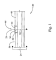
- Figure 1 is a cross sectional view of a structure in relation to which an apparatus for aligning a machine tool may be used in accordance with one implementation of the disclosure
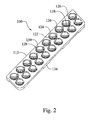
- Figure 2 is a top perspective view of a machine plate in accordance with one implementation of the disclosure.
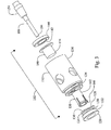
- Figure 3 is an exploded side perspective view of a nosepiece and plate bushing in accordance with one implementation of the disclosure
- Figure 4 is a perspective view of a plate bushing in accordance with one implementation of the disclosure.
- Figure 5 is a perspective view of a distal end of a nosepiece housing in accordance with one implementation of the disclosure
- Figure 6 is a side view of a nosepiece attached to a plate bushing in accordance with one implementation of the disclosure
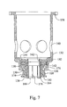
- Figure 7 is a longitudinal sectional view of a nosepiece and a plate bushing in accordance with one implementation of the disclosure, the nosepiece shown in an unclamped position;
- Figure 8 is a top plan view of a plate bushing centered over a target bushing in accordance with one implementation of the disclosure
- Figure 9 is a side perspective view of a nosepiece in clamped position in accordance with one implementation of the disclosure.
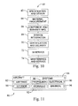
- Figure 10 is a flow diagram of aircraft production and service methodology
- Figure 11 is a block diagram of an aircraft
- Figure 12 is a block diagram of an apparatus for aligning a machine tool with a target location on a structure in clamped position in accordance with one implementation of the disclosure.
- Figure 13 is a flow diagram of a method of aligning a machine tool with a target location on a structure in accordance with one implementation of the disclosure.
- exemplary method 60 may include specification and design 62 of the aircraft 80 and material procurement 64.
- component and subassembly manufacturing 66 and system integration 68 of the aircraft 80 takes place.
- the aircraft 80 may go through certification and delivery 70 in order to be placed in service 72.
- routine maintenance and service 74 which may also include modification, reconfiguration, refurbishment, and so on).
- a system integrator may include without limitation any number of aircraft manufacturers and major-system subcontractors; a third party may include without limitation any number of venders, subcontractors, and suppliers; and an operator may be an airline, leasing company, military entity, service organization, and so on.
- the aircraft 80 produced by exemplary method 60 may include an airframe 82 with a plurality of systems 84 and an interior 86.
- high-level systems 84 include one or more of a propulsion system 88, an electrical system 90, a hydraulic system 92, and an environmental system 94. Any number of other systems may be included.
- an aerospace example is shown, the principles of the invention may be applied to other industries, such as the automotive industry.
- Apparatus and methods embodied herein may be employed during any one or more of the stages of the production and service method 60.
- components or subassemblies corresponding to production process 66 may be fabricated or manufactured in a manner similar to components or subassemblies produced while the aircraft 80 is in service.
- one or more apparatus embodiments, method embodiments, or a combination thereof may be utilized during the production stages 66 and 68, for example, by substantially expediting assembly of or reducing the cost of an aircraft 80.
- apparatus embodiments, method embodiments, or a combination thereof may be utilized while the aircraft 80 is in service, for example and without limitation, to maintenance and service 74.
- the present disclosure is directed to methods and apparatus for aligning a machine tool with a target location on a structure.
- the machine tool may be operable, for example, using an orbital drilling unit or other machining module.
- Various implementations of the disclosure make it possible to perform machining at a target location that could deviate from a nominal machining location.
- FIG. 12 A block diagram of one configuration of an apparatus for aligning a machine tool with a target location on a structure is indicated generally in Figure 12 by reference number 200.
- the apparatus 200 includes a machine plate 204 positionable on the structure.
- the plate has a plate bushing 208 that provides a hole through the machine plate 204.
- the apparatus also includes a nosepiece 212 for guiding a distal end of the tool (not shown) through the plate bushing 208 to the target location (not shown).
- the nosepiece 212 has a collet 216 configured to be moved at least partly through and sideward in the plate bushing 208 to center the nosepiece 212 on an element (not shown) projecting from the structure at the target location.
- the nosepiece 212 is configured for attachment to the plate bushing 208 to establish a predefined approach angle of the tool relative to the projecting element.
- the disclosure could be implemented in connection with many types of machines and/or tools, including but not limited to cutting machines and tools and non-orbital drills. Power feed or positive feed drill motors, plasma cutting torches, water jet nozzles, laser drilling and/or marking equipment, hole saws, broaching heads, and/or various types of machining heads could be adapted for use in accordance with the disclosure. Additionally, although various implementations may be described with reference to splicing applications, the disclosure is not so limited. The disclosure can be implemented in many applications in which it may be desirable to center a machine tool over a machining location and to utilize the tool along a specific vector or approach angle relative to that location.
- An exemplary cross section of a structure in which splicing may be performed is indicated generally in Figure 1 by reference number 20.
- An orbital drilling unit may be used in accordance with one implementation of the disclosure to drill, e . g ., through several aligned parts 24.
- the parts 24 may be made of different materials, including but not limited to carbon fiber reinforced plastics, metals, etc .
- drilling is to be performed in a plurality of target locations 28, one of which is shown in Figure 1 .
- Drilling is to be performed along a path 30 through the parts 24, beginning at the target location 28, which is defined by a bushing 32 that lines a hole 36 in an upper splice plate 40.
- Such a bushing may be referred to in this disclosure and the claims as a "target bushing".
- drilling may be specified to be performed at a nominal location indicated generally by reference number 46. It should be noted, however, that the nominal drilling location 46 may or may not coincide exactly with the target location 28, dependent, e.g., on tolerances provided in the nominal drilling specification.
- a flange 50 of the target bushing 32 projects from an upper surface 54 of the structure 20.
- FIG. 2 and 3 Various configurations of an apparatus for aligning a machine tool with a target location on a structure include a machine plate and a nosepiece, e.g., as shown in Figures 2 and 3 .
- a target location may be, for example, the target bushing 32 installed in the structure 20, and various aligning apparatus configurations are described below with reference to the structure 20 and target bushing 32. It should be noted, however, that various implementations are contemplated in relation to other types of target locations. For example, the presence of a hole is not necessary at a target location for configurations of the apparatus to align a machine tool.
- the disclosure could be implemented in relation to elements other than bushings that project from a structural surface, e.g. nail heads, screw heads, etc . Although such projections could be circular and/or spherical, they could have other or additional shapes.
- FIG. 1 One configuration of a machine plate is indicated generally in Figure 2 by reference number 100.
- FIG. 3 One configuration of a nosepiece is indicated generally in Figure 3 by reference number 102.
- the nosepiece 102 may be used to guide a distal end 104 of a machine tool 108 through the machine plate 100 to a target drilling location 28 on the structure 20.
- the machine tool 108 is, e . g ., a cutting tool operable via an orbital drill unit (not shown in Figure 3 ).
- the terms "proximal” and distal” are used with reference to a user of the machine tool 108.
- the machine plate 100 may be positioned on and attached to the structure surface 54.
- the machine plate 100 has a body 112 made, for example, of solid aluminum that may be elevated from the surface 54, e . g ., by a plurality of supports 116.
- a plurality of plate bushings 120 are mounted in the machine plate body 112 to provide a plurality of holes 118 through the body 112.
- Each bushing 120 may be positioned over a corresponding target drilling location on the structure 20.
- the bushings 120 are configured to establish normality of a machine tool relative to a target location as further described below.
- plate bushings may be configured to establish an approach angle for a machine tool at other than ninety degrees. It should be noted generally that machine plate configurations of various shapes and having various dimensions and numbers of holes, including configurations having a single hole, are contemplated.
- each plate bushing 120 has a distal portion 122 fixedly mounted in the machine plate body 112 and a proximal portion 124 extending above a proximal surface 126 of the machine plate body 112.
- a plate bushing 120 may be made, e . g ., of hardened tool steel and is shown in greater detail in Figures 3 and 4 .
- the plate bushing proximal portion 124 has a projecting rim 128 that is graspable by the nosepiece 102 as further described below.
- the bushing rim 128 includes a plurality of lobes 130.
- the nosepiece 102 includes a plurality of substantially concentric components, e . g ., a housing 132 having a proximal portion 134 and a distal portion 136, a collet 138, a collet clamp 140, a piston 142 and piston cylinder 144.
- the housing 132 may be made from one solid piece of steel, e . g ., heat treatable stainless or tool steel.
- the piston 142 and cylinder 144 may be fabricated, e . g ., of stainless steel.
- the distal portion 136 of the nosepiece housing 132 is configured to mate with lobes 130 of the plate bushing 120. Specifically, an end 146 of the distal portion 136 has a hole 148 shaped to fit over the lobes 130 when a user positions the nosepiece relative to the plate bushing 120. As further described below, a user may cause the nosepiece housing 132 to be locked onto the lobes 130 through slots 152 and to be pressed against a distal surface 150 (shown in Figure 7 ) provided by the lobes 130.
- the cutting tool 108 is held by a tool holder 154 configured for attachment to an orbital drill unit 156.
- the orbital drill unit 156 and attached cutting tool 108 may be rigidly connected with the nosepiece housing 132 at a plurality of housing flanges 158, two of which are shown in Figure 6 .
- the tool holder 154 provides a standard interface, e . g ., a HSK mount and heat shrink tool holder interface, between the tool 108 and the orbital drilling unit 156.
- the nosepiece housing 132 includes lateral holes 160 for chip evacuation via an external vacuum system and duct (not shown).
- a proximal portion 162 of the collet 138 is rigidly fixed to the nosepiece housing 132 through the piston cylinder 144.
- a slotted distal portion 164 of the collet extending from the housing 132 includes a lip 166.
- the collet may be made of a single piece of material, e.g., of heat treatable stainless or tool steel. Slots 178 allow the machined diameter of the contacting surface of the lip 166 to contract as the collet clamp 140 slides over the distal portion 164 of the collet.
- the lip 166 is configured to fit over the protruding flange 50 of the bushing 32.
- a collet could be configured to fit over an element of a different type and/or having a different shape projecting from a work piece surface.
- the nosepiece 102 with integral collet 138 is configured for radial movement in the plate bushing 120 to allow centering of the collet 138 with fixed nosepiece 102 on the target bushing flange 50. Accordingly, dimensions of the plate bushing 120 are based on dimensions of the target bushing 32 and collet 138, e . g ., as shown in Figure 8.
- Figure 8 is a top plan view of the plate bushing 120 centered over the target bushing 32.
- An inner diameter 168 of the plate bushing 120 may be established by adding twice the wall thickness of the collet 138 to an amount of leeway to a diameter 170 of the target bushing flange 50.
- the resulting plate bushing inner diameter 168 allows radial displacement of the collet 138 by 0.025 inches from a nominal drill location when the collet 138 is moved in the plate bushing 120 to center the nosepiece 102 on the target bushing flange 50.
- leeway for radial movement of the collet 138 is a function of the difference in diameters 168 and 170 and the outside dimension of the collet clamp 140 divided by two.
- An outer diameter 172 of the plate bushing 120 may be, e . g ., a standard size used in drill plate fabrication.
- the machine plate 100 and plate supports 116 are fabricated to provide a machine plate height that allows each plate bushing 120 to be at an appropriate height from the work piece surface 54 to ensure sufficient contact by the collet 138 over the target bushing flange 50.
- the collet clamp 140 has a distal end 174 configured to be extended over the collet 138 to clamp the collet 138 onto the target bushing flange 50.
- the clamp 140 may be made from a highly elastic material, e . g ., acetal copolymer. Such material allows the collet 138 to close around a target bushing flange within a predetermined vicinity of, e . g ., plus or minus 0.010 inch diametric from, a nominal target bushing flange outside dimension and still substantially close a gap 176 (shown in Figure 7 ) between the nosepiece housing, plate bushing 120 and collet clamp 140.
- An air hose 180 (shown in Figure 6 ) extending from an air pressure/vacuum system (not shown) into the housing 132 pneumatically connects the pressure/vacuum system with a space 182 defined in the piston cylinder 144.
- the piston 142 is rigidly attached to the clamp 140 and operable to push the clamp 140 at least partially through the housing 132 to clamp the collet 138 onto the target bushing flange 50 and the housing 132 onto the plate bushing 120.
- the housing 132 may be clamped onto the plate bushing 120 and against the lobe distal surface 150 to establish normality of the tool 108 relative to the target bushing flange 50.
- a machine assembly that includes the foregoing aligning apparatus may be combined with an orbital drill unit and used in the following manner.
- a user installs the tool 108 in the tool holder 154 and installs the tool holder 154 in the orbital drill unit 156.
- the user then affixes the orbital drill unit to the proximal flanges 158 of the nosepiece housing 132 so that the tool 108 is extendable through the nosepiece 102.
- the machine plate 100 is positioned over the structure 20 so that one or more plate bushings 120 are positioned over one or more target drilling locations 28, e . g ., over one or more target bushing flanges 50 projecting from the structure surface 54. Placement of the machine plate may be in accordance with nominal drilling location specifications.
- the user inserts the nosepiece 102 into a plate bushing 120 so that distal ends of the collet 138 and clamp 140 extend through the plate bushing 120 toward a target bushing flange 50.
- the user may "float" the drill unit motor, keeping the tool distal end 104 retracted from the plate bushing 120, and may move the collet 138 longitudinally and/or sideward in the plate bushing until the collet 138 is centered on the bushing flange 50.
- the user may rotate the nosepiece, e .
- the piston 142 can be actuated toward the distal end of the housing 132 to lock the plate bushing lobes 130 into the distal end 146 of the nosepiece housing 132. It should be noted that unless the collet 138 is positioned over and onto the target bushing flange 50, the nosepiece 102 cannot be rotated and therefore cannot be locked onto the plate bushing lobes 130. In such manner, incorrect positioning of the collet onto the flange 50 can be avoided.
- the user may activate the clamp 140 by introducing gas or hydraulic pressure, e.g., air from the air pressure system through the air hose 180 into the piston cylinder 144.
- Air pressure may be supplied in the piston cylinder at between about 100 and 200 pounds per square inch. In some configurations, air pressure as high as about 400 pounds per square inch could be supplied in the cylinder 144.
- the pressure causes the piston 142 to push the clamp 140 distally in the piston cylinder 144.
- the clamp 140 closes the collet 138 around the flange 50 of the target bushing 32, centering the machine tool 108 and drill unit 156 over the target bushing 32.
- the clamp also clamps the nosepiece 102 against the plate bushing lobes 130.
- the nosepiece is forced against the lobe surface 150, thereby bringing the machine tool 108 and drill unit 156 into normality with the target bushing 32.
- This double clamping action caused by a single stroke of the piston 142, restrains the nosepiece 102 and drill unit in the machine plate 100 in six degrees of freedom.
- the drill unit 156 can then be used to drill through the target bushing 32.
- the nosepiece 102 is shown in Figure 9 in clamped position.
- the user activates the air system to create a vacuum in the piston cylinder 144, thereby causing the piston 142 to withdraw the clamp 140 and allow the nosepiece 102 to be removed from the target bushing flange 50 and plate bushing lobes 130.
- the clamp 140 could be operated in other or additional ways. For example, manual operation of a collet clamp is contemplated in some implementations. It also should be noted that many different types of grasping mechanisms could be used in place of the rim 128 and lobes 130. For example, the rim and/or nosepiece distal end could include various contours instead of or in addition to flat surfaces.
- a flow diagram of a method of aligning a machine tool with a target location on a structure in accordance with one implementation of the disclosure is indicated generally in Figure 13 by reference number 300.
- the distal end of the machine tool is inserted into a nosepiece for guiding a distal end of the tool.
- the nosepiece has a housing and a collet attached to and extending distally from the housing.
- a distal end of the collet is inserted through a plate bushing in a machine plate positioned over an element projecting from the structure at the target location.
- the collet is moved radially in the plate bushing to center the collet distal end over the element projecting from the structure.
- the centered collet distal end is affixed to the projecting element.
- a distal end of the housing is affixed to the plate bushing.
- the foregoing apparatus and methods make it possible to use nominal specifications to position a drill plate over a work piece and then to perform drilling based on the location of a "landmark" on the underlying structure.
- Configurations of the machine plate and nosepiece interface make it possible to achieve both concentricity and normality in hole processing. It is possible for drilling to deviate from nominal locations while ensuring that a final hole is processed concentric with a required target location, e . g ., an installed bushing.
- the drill unit and nosepiece can be inserted into a plurality of plate bushings to drill a plurality of hole locations without having to reinstall the tool in the nosepiece or perform other time consuming steps.
- a single-acting cylinder provides the force sufficient to close the collet that finds the center of an installed work piece bushing and provides normality and rigidity for an orbital drill unit to process a hole.
- the center line of a hole is not determined by a drill bushing but rather by the location of an installed bushing or other projecting element on the structure.
- the above aligning apparatus can be used in orbital drilling, the benefits of which can include the ability to obtain a plurality of hole diameters from a single cutter, low cutting forces, high surface-feet-per-minute machining of carbon fiber composite, stainless steel and/or titanium structure, minimal entry and/or exit burr and virtually no composite delamination.
- a simple interface with an orbital drill motor is provided, along with the ability to quickly locate the centerline of a fastener.
- the "insert, rotate, and lock" process to be followed by an operator is simple and quick to perform. The process is highly visible to an operator, and since there is a dedicated plate bushing size for each fastener diameter, errors can be reduced or eliminated.
Applications Claiming Priority (1)
| Application Number | Priority Date | Filing Date | Title |
|---|---|---|---|
| US11/832,269 US7611314B2 (en) | 2007-08-01 | 2007-08-01 | Aligning a machine tool with a target location on a structure |
Publications (2)
| Publication Number | Publication Date |
|---|---|
| EP2025439A1 true EP2025439A1 (de) | 2009-02-18 |
| EP2025439B1 EP2025439B1 (de) | 2011-03-30 |
Family
ID=39751748
Family Applications (1)
| Application Number | Title | Priority Date | Filing Date |
|---|---|---|---|
| EP08161685A Active EP2025439B1 (de) | 2007-08-01 | 2008-08-01 | Ausrichten eines Maschinenwerkzeugs mit einem Zielort auf einer Struktur |
Country Status (7)
| Country | Link |
|---|---|
| US (4) | US7611314B2 (de) |
| EP (1) | EP2025439B1 (de) |
| CN (1) | CN101357442B (de) |
| AT (1) | ATE503599T1 (de) |
| CA (4) | CA2939601C (de) |
| DE (1) | DE602008005812D1 (de) |
| ES (1) | ES2363825T3 (de) |
Cited By (2)
| Publication number | Priority date | Publication date | Assignee | Title |
|---|---|---|---|---|
| FR2952841A1 (fr) * | 2009-11-26 | 2011-05-27 | Airbus Operations Sas | Dispositif pour le percage d'un panneau complexe |
| EP2682210B1 (de) * | 2012-07-02 | 2020-03-11 | Subaru Corporation | Bohreransteuerungsvorrichtung und Bohreransteuerungsverfahren |
Families Citing this family (18)
| Publication number | Priority date | Publication date | Assignee | Title |
|---|---|---|---|---|
| US7934892B2 (en) * | 2006-12-13 | 2011-05-03 | The Boeing Company | Collet clamping nosepiece for power feed drilling equipment |
| JP2010524711A (ja) * | 2007-04-27 | 2010-07-22 | ノヴェーター・アーベー | 可動式穴加工ユニットのための固定装置 |
| US7611314B2 (en) * | 2007-08-01 | 2009-11-03 | The Boeing Company | Aligning a machine tool with a target location on a structure |
| FR2934966B1 (fr) * | 2008-08-12 | 2010-09-17 | Airbus France | Systeme de percage et procede |
| CN101929311A (zh) * | 2009-06-18 | 2010-12-29 | 杭州博锋金刚石工具有限公司 | 一种竖直面打孔用定位冷却装置 |
| KR101224859B1 (ko) * | 2010-09-13 | 2013-01-22 | 국방과학연구소 | 진공력을 이용한 가공용 콜렛 척 및 이를 포함하는 가공장치 |
| US8870171B2 (en) * | 2011-02-14 | 2014-10-28 | General Electric Company | Shroud retaining pin extraction systems and methods |
| US9108363B2 (en) | 2011-10-06 | 2015-08-18 | The Boeing Company | Thin wall bushing for robust electrical bonding to fiber-reinforced structures |
| US9370819B2 (en) * | 2012-04-02 | 2016-06-21 | The Boeing Company | Collar installation end effector |
| US9108250B1 (en) | 2012-10-31 | 2015-08-18 | The Boeing Company | Adjustable bushing assemblies |
| US9643260B2 (en) | 2014-01-22 | 2017-05-09 | The Boeing Company | Systems and methods for forming an opening in a stack |
| US10183340B2 (en) * | 2014-06-27 | 2019-01-22 | The Boeing Company | Twist lock tool system |
| CN104139342B (zh) * | 2014-08-07 | 2016-07-20 | 天津航天长征火箭制造有限公司 | 大厚径比平板圆孔加工方法 |
| CN107073596B (zh) * | 2015-03-06 | 2020-06-30 | 里奇工具公司 | 孔锯钻引导器 |
| CN107571048A (zh) * | 2017-09-06 | 2018-01-12 | 深圳市贵峰精密有限公司 | 一种工件的定位装置和定位方法 |
| CN107984259A (zh) * | 2017-12-04 | 2018-05-04 | 佛山科学技术学院 | 一种圆管钻孔辅助器 |
| CN112757239A (zh) * | 2021-01-26 | 2021-05-07 | 西峡县飞龙汽车部件有限公司 | 一种衬套压装高度及缩口间隙自动检测的装置 |
| CN114549647B (zh) * | 2022-04-22 | 2022-08-12 | 成都飞机工业(集团)有限责任公司 | 一种hsk刀柄摆放朝向的检测方法 |
Citations (4)
| Publication number | Priority date | Publication date | Assignee | Title |
|---|---|---|---|---|
| EP0761351A1 (de) * | 1995-08-31 | 1997-03-12 | Cooper Industries, Inc. | Konzentrische zweiteilige Spannzange |
| WO2002102535A1 (en) * | 2001-06-18 | 2002-12-27 | Novator Ab | Fixation device for a portable orbital drilling unit |
| WO2006088404A1 (en) * | 2005-02-16 | 2006-08-24 | Novator Ab | A fixation device for fixating a portable orbital drilling machine to a drilling template |
| DE202007002845U1 (de) * | 2007-02-27 | 2007-06-14 | Johannes Lübbering AG | Bohrschablone |
Family Cites Families (46)
| Publication number | Priority date | Publication date | Assignee | Title |
|---|---|---|---|---|
| US2839953A (en) * | 1955-10-24 | 1958-06-24 | Boeing Co | Drill motor collet mounts |
| US2935905A (en) * | 1956-12-10 | 1960-05-10 | Winslow Product Engineering Co | Collet foot attachment for pneumatic power drill |
| US3575519A (en) * | 1969-06-02 | 1971-04-20 | Russell L Bruner | Drill guide assembly |
| US4199283A (en) * | 1978-09-25 | 1980-04-22 | Perry Larelle T | Drill jig |
| US4269550A (en) * | 1980-03-14 | 1981-05-26 | Digiulio Mario | Drill bushing for use in a metal tooling plate |
| US4391558A (en) * | 1980-12-01 | 1983-07-05 | Perry Larelle T | Drill jig |
| FR2562179B1 (fr) * | 1984-04-02 | 1986-08-14 | Recoules Fils | Dispositif de fixation automatique d'un outillage sur un support |
| SU1321532A1 (ru) * | 1985-02-27 | 1987-07-07 | Предприятие П/Я М-5873 | Устройство дл креплени дрели |
| FR2588495B1 (fr) * | 1985-10-16 | 1987-12-11 | Aerospatiale | Ensemble de douille de fixation pour unite d'usinage et unite d'usinage adaptee pour cooperer avec ladite douille |
| DE3819407A1 (de) * | 1988-06-07 | 1989-12-21 | Gerhard Rall | Spannzange |
| DE4009940C2 (de) * | 1990-03-28 | 1997-07-17 | Straus Gerhard | Einrichtung zur spanabhebenden Bearbeitung von Werkstücken |
| US5054968A (en) * | 1990-10-18 | 1991-10-08 | Dresser Industries, Inc. | Mechanical positive feed drill with supported spindle |
| FR2680329B3 (fr) * | 1991-08-14 | 1993-11-26 | Recoules Fils Ets | Dispositif de verrouillage d'un outillage sur un support. |
| JPH0537451U (ja) * | 1991-10-22 | 1993-05-21 | 日本ミクロコーテイング株式会社 | 円盤状デイスク固定装置 |
| FR2703280B1 (fr) * | 1993-04-02 | 1996-07-12 | Recoules Fils Ets | Procédé et dispositif de montage d'outillages. |
| US5395187A (en) * | 1993-11-22 | 1995-03-07 | Mcdonnell Douglas Corporation | Method and apparatus for attaching a drill motor to a drill plate with a clamping device having an expandable collet |
| DE4431952A1 (de) * | 1994-09-08 | 1996-03-14 | Werner Dr Ing Poenitzsch | Bohrschablone |
| US5482411A (en) * | 1994-12-22 | 1996-01-09 | Mcdonnell Douglas Corporation | Method and apparatus for securely clamping a drill motor to a drill plate |
| US5584618A (en) * | 1995-05-09 | 1996-12-17 | Mcdonnell Douglas Corporation | Pneumatically actuated drill motor and an associated method and apparatus for clamping the drill motor to a drill plate |
| JP3518443B2 (ja) * | 1998-10-09 | 2004-04-12 | トヨタ自動車株式会社 | 機械加工方法 |
| US6382890B1 (en) * | 1999-09-01 | 2002-05-07 | Novator Ab | Hand tool apparatus for orbital drilling |
| US6719505B2 (en) * | 1999-09-01 | 2004-04-13 | Novator Ab | Orbital hand tool apparatus for drilling |
| US6467385B1 (en) | 1999-12-03 | 2002-10-22 | The Boeing Company | Panel trimming system |
| US6533292B2 (en) * | 2000-03-20 | 2003-03-18 | Production Dynamics | Pull-to-close collet chuck |
| US6514018B2 (en) * | 2001-03-22 | 2003-02-04 | The Boeing Company | Pneumatic drilling end effector |
| US6843328B2 (en) | 2001-12-10 | 2005-01-18 | The Boeing Company | Flexible track drilling machine |
| US6722447B2 (en) | 2002-05-01 | 2004-04-20 | The Boeing Company | Concentric pneumatic/hydraulic power feed apparatus |
| US7498796B2 (en) | 2002-05-09 | 2009-03-03 | The Boeing Company | Magnetic indexer for high accuracy hole drilling |
| US6905291B2 (en) | 2002-05-30 | 2005-06-14 | The Boeing Company | Apparatus and method for drilling holes and optionally inserting fasteners |
| DE60334813D1 (de) * | 2002-09-16 | 2010-12-16 | Novator Ab | Vorrichtung zur befestigung einer tragbaren bohr- oder fräsmaschine an einer schablone zur herstellung von löchern in einem werkstück |
| US6832433B2 (en) * | 2003-03-03 | 2004-12-21 | Rockford Products Corporation | Machining apparatus and method of using same |
| US6971824B2 (en) * | 2003-05-06 | 2005-12-06 | The Boeing Company | Locking nosepiece and template |
| CA2526893C (en) | 2003-05-14 | 2010-10-26 | Japan Science And Technology Agency | Inhibition of the expression of huntingtin gene |
| US7264426B2 (en) | 2003-06-25 | 2007-09-04 | The Boeing Company | Apparatus and methods for servo-controlled manufacturing operations |
| US7137760B2 (en) | 2003-06-25 | 2006-11-21 | The Boeing Company | Methods and apparatus for manufacturing operations using opposing-force support systems |
| US6926094B2 (en) | 2003-06-25 | 2005-08-09 | The Boeing Company | Apparatus for manufacturing operations using non-contact position sensing |
| US7488144B2 (en) | 2003-06-25 | 2009-02-10 | The Boeing Company | Methods and apparatus for track members having a neutral-axis rack |
| JP4007603B2 (ja) | 2003-07-31 | 2007-11-14 | キヤノン株式会社 | 記録紙収納パック |
| US20050052898A1 (en) | 2003-09-05 | 2005-03-10 | Arntson Paul R. | Apparatus and methods for magnetic through-skin sensing |
| US7406758B2 (en) | 2003-09-05 | 2008-08-05 | The Boeing Company | Apparatus and methods for manufacturing operations |
| US7384220B2 (en) * | 2004-01-06 | 2008-06-10 | The Boeing Company | Laser-guided coordination hole drilling |
| US7134649B2 (en) | 2004-05-27 | 2006-11-14 | The Boeing Company | Conformal vacuum cup apparatus and method |
| US7216408B2 (en) | 2004-05-27 | 2007-05-15 | The Boeing Company | Flexible rail multiaxis machine tool and method |
| US7364388B2 (en) * | 2004-07-13 | 2008-04-29 | Johannes Luebbering Ag/Switzerland | Multi-layer drilling template and method of drilling using the template |
| US7469907B2 (en) * | 2004-11-10 | 2008-12-30 | Hydra-Lock Corporation | Mechanically actuated workpiece holder including a plastic collet |
| US7611314B2 (en) * | 2007-08-01 | 2009-11-03 | The Boeing Company | Aligning a machine tool with a target location on a structure |
-
2007
- 2007-08-01 US US11/832,269 patent/US7611314B2/en active Active
-
2008
- 2008-07-16 CA CA2939601A patent/CA2939601C/en active Active
- 2008-07-16 CA CA2986498A patent/CA2986498A1/en not_active Abandoned
- 2008-07-16 CA CA2872254A patent/CA2872254C/en active Active
- 2008-07-16 CA CA2637961A patent/CA2637961C/en active Active
- 2008-08-01 CN CN2008101455066A patent/CN101357442B/zh active Active
- 2008-08-01 EP EP08161685A patent/EP2025439B1/de active Active
- 2008-08-01 ES ES08161685T patent/ES2363825T3/es active Active
- 2008-08-01 DE DE602008005812T patent/DE602008005812D1/de active Active
- 2008-08-01 AT AT08161685T patent/ATE503599T1/de not_active IP Right Cessation
- 2008-08-14 US US12/191,671 patent/US8057137B2/en active Active
- 2008-08-28 US US12/231,072 patent/US7901165B2/en active Active
-
2009
- 2009-08-27 US US12/549,020 patent/US7914242B2/en active Active
Patent Citations (4)
| Publication number | Priority date | Publication date | Assignee | Title |
|---|---|---|---|---|
| EP0761351A1 (de) * | 1995-08-31 | 1997-03-12 | Cooper Industries, Inc. | Konzentrische zweiteilige Spannzange |
| WO2002102535A1 (en) * | 2001-06-18 | 2002-12-27 | Novator Ab | Fixation device for a portable orbital drilling unit |
| WO2006088404A1 (en) * | 2005-02-16 | 2006-08-24 | Novator Ab | A fixation device for fixating a portable orbital drilling machine to a drilling template |
| DE202007002845U1 (de) * | 2007-02-27 | 2007-06-14 | Johannes Lübbering AG | Bohrschablone |
Cited By (3)
| Publication number | Priority date | Publication date | Assignee | Title |
|---|---|---|---|---|
| FR2952841A1 (fr) * | 2009-11-26 | 2011-05-27 | Airbus Operations Sas | Dispositif pour le percage d'un panneau complexe |
| WO2011067517A1 (fr) * | 2009-11-26 | 2011-06-09 | Airbus Operations (S.A.S) | Dispositif pour le perçage d'un panneau complexe |
| EP2682210B1 (de) * | 2012-07-02 | 2020-03-11 | Subaru Corporation | Bohreransteuerungsvorrichtung und Bohreransteuerungsverfahren |
Also Published As
| Publication number | Publication date |
|---|---|
| US7611314B2 (en) | 2009-11-03 |
| CA2637961C (en) | 2015-03-17 |
| CA2637961A1 (en) | 2009-02-01 |
| CA2872254A1 (en) | 2009-02-01 |
| CA2986498A1 (en) | 2009-02-01 |
| US20100047029A1 (en) | 2010-02-25 |
| CA2939601C (en) | 2018-01-02 |
| US7914242B2 (en) | 2011-03-29 |
| ES2363825T3 (es) | 2011-08-17 |
| DE602008005812D1 (de) | 2011-05-12 |
| CN101357442B (zh) | 2010-06-16 |
| US8057137B2 (en) | 2011-11-15 |
| CA2872254C (en) | 2016-10-11 |
| CA2939601A1 (en) | 2009-02-01 |
| US7901165B2 (en) | 2011-03-08 |
| ATE503599T1 (de) | 2011-04-15 |
| EP2025439B1 (de) | 2011-03-30 |
| US20090035085A1 (en) | 2009-02-05 |
| US20090035084A1 (en) | 2009-02-05 |
| CN101357442A (zh) | 2009-02-04 |
| US20090035080A1 (en) | 2009-02-05 |
Similar Documents
| Publication | Publication Date | Title |
|---|---|---|
| CA2872254C (en) | Aligning a machine tool with a target location on a structure | |
| CN1092555C (zh) | 确定性机翼装配 | |
| US8210778B2 (en) | Method and device for clamping and machining | |
| US5947654A (en) | Drill/countersink nosepiece assembly | |
| US20030049085A1 (en) | Fixation device for a portable orbital drilling unit | |
| Whinnem et al. | Development of orbital drilling for the Boeing 787 | |
| US7934892B2 (en) | Collet clamping nosepiece for power feed drilling equipment | |
| EP3375565A1 (de) | Maschinenwerkzeug | |
| US6012877A (en) | Self-centering end effector | |
| CN102294611A (zh) | 加工连杆小头斜面的夹具 | |
| JP2008110438A (ja) | 穿孔装置 | |
| US9415452B2 (en) | Tool holder attaching/detaching structure of machine tool | |
| US20100166519A1 (en) | Clamping method for workpieces used for the production of compressor or turbine wheels | |
| US8454282B2 (en) | Fixture and method for mounting angled machine head on a machine tool | |
| JP4336558B2 (ja) | 治具プレート | |
| CN105290849A (zh) | 搭载有旋转对称体的夹紧夹具的机床 | |
| US11850667B2 (en) | Chuck jaw stopping mechanism | |
| CN106964796B (zh) | 高度设定工具和方法 | |
| CN102672225A (zh) | 机械式定位卡盘 | |
| US9095935B1 (en) | Method for holding parts during manufacturing processing | |
| CN116638120A (zh) | 一种气瓶瓶口销钉安装孔的加工机构及使用方法 | |
| CN115743586A (zh) | 组装框架的方法及用于制造具有框架的飞行器外壳的方法 | |
| CN116852131A (zh) | 飞机叠层交点孔精加工柔性试刀件装配体 |
Legal Events
| Date | Code | Title | Description |
|---|---|---|---|
| PUAI | Public reference made under article 153(3) epc to a published international application that has entered the european phase |
Free format text: ORIGINAL CODE: 0009012 |
|
| 17P | Request for examination filed |
Effective date: 20080804 |
|
| AK | Designated contracting states |
Kind code of ref document: A1 Designated state(s): AT BE BG CH CY CZ DE DK EE ES FI FR GB GR HR HU IE IS IT LI LT LU LV MC MT NL NO PL PT RO SE SI SK TR |
|
| AX | Request for extension of the european patent |
Extension state: AL BA MK RS |
|
| 17Q | First examination report despatched |
Effective date: 20090907 |
|
| AKX | Designation fees paid |
Designated state(s): AT BE BG CH CY CZ DE DK EE ES FI FR GB GR HR HU IE IS IT LI LT LU LV MC MT NL NO PL PT RO SE SI SK TR |
|
| GRAP | Despatch of communication of intention to grant a patent |
Free format text: ORIGINAL CODE: EPIDOSNIGR1 |
|
| GRAS | Grant fee paid |
Free format text: ORIGINAL CODE: EPIDOSNIGR3 |
|
| GRAA | (expected) grant |
Free format text: ORIGINAL CODE: 0009210 |
|
| AK | Designated contracting states |
Kind code of ref document: B1 Designated state(s): AT BE BG CH CY CZ DE DK EE ES FI FR GB GR HR HU IE IS IT LI LT LU LV MC MT NL NO PL PT RO SE SI SK TR |
|
| REG | Reference to a national code |
Ref country code: GB Ref legal event code: FG4D |
|
| REG | Reference to a national code |
Ref country code: CH Ref legal event code: EP |
|
| REG | Reference to a national code |
Ref country code: IE Ref legal event code: FG4D |
|
| REF | Corresponds to: |
Ref document number: 602008005812 Country of ref document: DE Date of ref document: 20110512 Kind code of ref document: P |
|
| REG | Reference to a national code |
Ref country code: DE Ref legal event code: R096 Ref document number: 602008005812 Country of ref document: DE Effective date: 20110512 |
|
| REG | Reference to a national code |
Ref country code: NL Ref legal event code: VDEP Effective date: 20110330 |
|
| PG25 | Lapsed in a contracting state [announced via postgrant information from national office to epo] |
Ref country code: LV Free format text: LAPSE BECAUSE OF FAILURE TO SUBMIT A TRANSLATION OF THE DESCRIPTION OR TO PAY THE FEE WITHIN THE PRESCRIBED TIME-LIMIT Effective date: 20110330 Ref country code: LT Free format text: LAPSE BECAUSE OF FAILURE TO SUBMIT A TRANSLATION OF THE DESCRIPTION OR TO PAY THE FEE WITHIN THE PRESCRIBED TIME-LIMIT Effective date: 20110330 Ref country code: GR Free format text: LAPSE BECAUSE OF FAILURE TO SUBMIT A TRANSLATION OF THE DESCRIPTION OR TO PAY THE FEE WITHIN THE PRESCRIBED TIME-LIMIT Effective date: 20110701 Ref country code: HR Free format text: LAPSE BECAUSE OF FAILURE TO SUBMIT A TRANSLATION OF THE DESCRIPTION OR TO PAY THE FEE WITHIN THE PRESCRIBED TIME-LIMIT Effective date: 20110330 Ref country code: SE Free format text: LAPSE BECAUSE OF FAILURE TO SUBMIT A TRANSLATION OF THE DESCRIPTION OR TO PAY THE FEE WITHIN THE PRESCRIBED TIME-LIMIT Effective date: 20110330 |
|
| REG | Reference to a national code |
Ref country code: ES Ref legal event code: FG2A Ref document number: 2363825 Country of ref document: ES Kind code of ref document: T3 Effective date: 20110817 |
|
| LTIE | Lt: invalidation of european patent or patent extension |
Effective date: 20110330 |
|
| PG25 | Lapsed in a contracting state [announced via postgrant information from national office to epo] |
Ref country code: FI Free format text: LAPSE BECAUSE OF FAILURE TO SUBMIT A TRANSLATION OF THE DESCRIPTION OR TO PAY THE FEE WITHIN THE PRESCRIBED TIME-LIMIT Effective date: 20110330 Ref country code: NO Free format text: LAPSE BECAUSE OF FAILURE TO SUBMIT A TRANSLATION OF THE DESCRIPTION OR TO PAY THE FEE WITHIN THE PRESCRIBED TIME-LIMIT Effective date: 20110630 Ref country code: SI Free format text: LAPSE BECAUSE OF FAILURE TO SUBMIT A TRANSLATION OF THE DESCRIPTION OR TO PAY THE FEE WITHIN THE PRESCRIBED TIME-LIMIT Effective date: 20110330 Ref country code: CY Free format text: LAPSE BECAUSE OF FAILURE TO SUBMIT A TRANSLATION OF THE DESCRIPTION OR TO PAY THE FEE WITHIN THE PRESCRIBED TIME-LIMIT Effective date: 20110330 Ref country code: AT Free format text: LAPSE BECAUSE OF FAILURE TO SUBMIT A TRANSLATION OF THE DESCRIPTION OR TO PAY THE FEE WITHIN THE PRESCRIBED TIME-LIMIT Effective date: 20110330 |
|
| PG25 | Lapsed in a contracting state [announced via postgrant information from national office to epo] |
Ref country code: BE Free format text: LAPSE BECAUSE OF FAILURE TO SUBMIT A TRANSLATION OF THE DESCRIPTION OR TO PAY THE FEE WITHIN THE PRESCRIBED TIME-LIMIT Effective date: 20110330 |
|
| PG25 | Lapsed in a contracting state [announced via postgrant information from national office to epo] |
Ref country code: EE Free format text: LAPSE BECAUSE OF FAILURE TO SUBMIT A TRANSLATION OF THE DESCRIPTION OR TO PAY THE FEE WITHIN THE PRESCRIBED TIME-LIMIT Effective date: 20110330 Ref country code: PT Free format text: LAPSE BECAUSE OF FAILURE TO SUBMIT A TRANSLATION OF THE DESCRIPTION OR TO PAY THE FEE WITHIN THE PRESCRIBED TIME-LIMIT Effective date: 20110801 |
|
| PG25 | Lapsed in a contracting state [announced via postgrant information from national office to epo] |
Ref country code: IS Free format text: LAPSE BECAUSE OF FAILURE TO SUBMIT A TRANSLATION OF THE DESCRIPTION OR TO PAY THE FEE WITHIN THE PRESCRIBED TIME-LIMIT Effective date: 20110730 Ref country code: CZ Free format text: LAPSE BECAUSE OF FAILURE TO SUBMIT A TRANSLATION OF THE DESCRIPTION OR TO PAY THE FEE WITHIN THE PRESCRIBED TIME-LIMIT Effective date: 20110330 Ref country code: RO Free format text: LAPSE BECAUSE OF FAILURE TO SUBMIT A TRANSLATION OF THE DESCRIPTION OR TO PAY THE FEE WITHIN THE PRESCRIBED TIME-LIMIT Effective date: 20110330 Ref country code: SK Free format text: LAPSE BECAUSE OF FAILURE TO SUBMIT A TRANSLATION OF THE DESCRIPTION OR TO PAY THE FEE WITHIN THE PRESCRIBED TIME-LIMIT Effective date: 20110330 |
|
| PG25 | Lapsed in a contracting state [announced via postgrant information from national office to epo] |
Ref country code: NL Free format text: LAPSE BECAUSE OF FAILURE TO SUBMIT A TRANSLATION OF THE DESCRIPTION OR TO PAY THE FEE WITHIN THE PRESCRIBED TIME-LIMIT Effective date: 20110330 Ref country code: MT Free format text: LAPSE BECAUSE OF FAILURE TO SUBMIT A TRANSLATION OF THE DESCRIPTION OR TO PAY THE FEE WITHIN THE PRESCRIBED TIME-LIMIT Effective date: 20110330 |
|
| PLBE | No opposition filed within time limit |
Free format text: ORIGINAL CODE: 0009261 |
|
| STAA | Information on the status of an ep patent application or granted ep patent |
Free format text: STATUS: NO OPPOSITION FILED WITHIN TIME LIMIT |
|
| PG25 | Lapsed in a contracting state [announced via postgrant information from national office to epo] |
Ref country code: DK Free format text: LAPSE BECAUSE OF FAILURE TO SUBMIT A TRANSLATION OF THE DESCRIPTION OR TO PAY THE FEE WITHIN THE PRESCRIBED TIME-LIMIT Effective date: 20110330 Ref country code: PL Free format text: LAPSE BECAUSE OF FAILURE TO SUBMIT A TRANSLATION OF THE DESCRIPTION OR TO PAY THE FEE WITHIN THE PRESCRIBED TIME-LIMIT Effective date: 20110330 |
|
| 26N | No opposition filed |
Effective date: 20120102 |
|
| PG25 | Lapsed in a contracting state [announced via postgrant information from national office to epo] |
Ref country code: MC Free format text: LAPSE BECAUSE OF NON-PAYMENT OF DUE FEES Effective date: 20110831 |
|
| REG | Reference to a national code |
Ref country code: DE Ref legal event code: R097 Ref document number: 602008005812 Country of ref document: DE Effective date: 20120102 |
|
| REG | Reference to a national code |
Ref country code: IE Ref legal event code: MM4A |
|
| PG25 | Lapsed in a contracting state [announced via postgrant information from national office to epo] |
Ref country code: IE Free format text: LAPSE BECAUSE OF NON-PAYMENT OF DUE FEES Effective date: 20110801 |
|
| REG | Reference to a national code |
Ref country code: CH Ref legal event code: PL |
|
| PG25 | Lapsed in a contracting state [announced via postgrant information from national office to epo] |
Ref country code: LI Free format text: LAPSE BECAUSE OF NON-PAYMENT OF DUE FEES Effective date: 20120831 Ref country code: CH Free format text: LAPSE BECAUSE OF NON-PAYMENT OF DUE FEES Effective date: 20120831 |
|
| PG25 | Lapsed in a contracting state [announced via postgrant information from national office to epo] |
Ref country code: LU Free format text: LAPSE BECAUSE OF NON-PAYMENT OF DUE FEES Effective date: 20110801 |
|
| PG25 | Lapsed in a contracting state [announced via postgrant information from national office to epo] |
Ref country code: BG Free format text: LAPSE BECAUSE OF FAILURE TO SUBMIT A TRANSLATION OF THE DESCRIPTION OR TO PAY THE FEE WITHIN THE PRESCRIBED TIME-LIMIT Effective date: 20110630 |
|
| PG25 | Lapsed in a contracting state [announced via postgrant information from national office to epo] |
Ref country code: TR Free format text: LAPSE BECAUSE OF FAILURE TO SUBMIT A TRANSLATION OF THE DESCRIPTION OR TO PAY THE FEE WITHIN THE PRESCRIBED TIME-LIMIT Effective date: 20110330 |
|
| PG25 | Lapsed in a contracting state [announced via postgrant information from national office to epo] |
Ref country code: HU Free format text: LAPSE BECAUSE OF FAILURE TO SUBMIT A TRANSLATION OF THE DESCRIPTION OR TO PAY THE FEE WITHIN THE PRESCRIBED TIME-LIMIT Effective date: 20110330 |
|
| REG | Reference to a national code |
Ref country code: FR Ref legal event code: PLFP Year of fee payment: 9 |
|
| REG | Reference to a national code |
Ref country code: FR Ref legal event code: PLFP Year of fee payment: 10 |
|
| REG | Reference to a national code |
Ref country code: FR Ref legal event code: PLFP Year of fee payment: 11 |
|
| P01 | Opt-out of the competence of the unified patent court (upc) registered |
Effective date: 20230516 |
|
| PGFP | Annual fee paid to national office [announced via postgrant information from national office to epo] |
Ref country code: IT Payment date: 20230822 Year of fee payment: 16 Ref country code: GB Payment date: 20230828 Year of fee payment: 16 Ref country code: ES Payment date: 20230901 Year of fee payment: 16 |
|
| PGFP | Annual fee paid to national office [announced via postgrant information from national office to epo] |
Ref country code: FR Payment date: 20230825 Year of fee payment: 16 Ref country code: DE Payment date: 20230829 Year of fee payment: 16 |