EP2022984A1 - Elektrischer verdichter - Google Patents
Elektrischer verdichter Download PDFInfo
- Publication number
- EP2022984A1 EP2022984A1 EP07743457A EP07743457A EP2022984A1 EP 2022984 A1 EP2022984 A1 EP 2022984A1 EP 07743457 A EP07743457 A EP 07743457A EP 07743457 A EP07743457 A EP 07743457A EP 2022984 A1 EP2022984 A1 EP 2022984A1
- Authority
- EP
- European Patent Office
- Prior art keywords
- inverter
- housing
- electric compressor
- electric motor
- electric
- Prior art date
- Legal status (The legal status is an assumption and is not a legal conclusion. Google has not performed a legal analysis and makes no representation as to the accuracy of the status listed.)
- Withdrawn
Links
Images


Classifications
-
- F—MECHANICAL ENGINEERING; LIGHTING; HEATING; WEAPONS; BLASTING
- F04—POSITIVE - DISPLACEMENT MACHINES FOR LIQUIDS; PUMPS FOR LIQUIDS OR ELASTIC FLUIDS
- F04C—ROTARY-PISTON, OR OSCILLATING-PISTON, POSITIVE-DISPLACEMENT MACHINES FOR LIQUIDS; ROTARY-PISTON, OR OSCILLATING-PISTON, POSITIVE-DISPLACEMENT PUMPS
- F04C23/00—Combinations of two or more pumps, each being of rotary-piston or oscillating-piston type, specially adapted for elastic fluids; Pumping installations specially adapted for elastic fluids; Multi-stage pumps specially adapted for elastic fluids
- F04C23/008—Hermetic pumps
-
- F—MECHANICAL ENGINEERING; LIGHTING; HEATING; WEAPONS; BLASTING
- F04—POSITIVE - DISPLACEMENT MACHINES FOR LIQUIDS; PUMPS FOR LIQUIDS OR ELASTIC FLUIDS
- F04C—ROTARY-PISTON, OR OSCILLATING-PISTON, POSITIVE-DISPLACEMENT MACHINES FOR LIQUIDS; ROTARY-PISTON, OR OSCILLATING-PISTON, POSITIVE-DISPLACEMENT PUMPS
- F04C18/00—Rotary-piston pumps specially adapted for elastic fluids
- F04C18/30—Rotary-piston pumps specially adapted for elastic fluids having the characteristics covered by two or more of groups F04C18/02, F04C18/08, F04C18/22, F04C18/24, F04C18/48, or having the characteristics covered by one of these groups together with some other type of movement between co-operating members
- F04C18/34—Rotary-piston pumps specially adapted for elastic fluids having the characteristics covered by two or more of groups F04C18/02, F04C18/08, F04C18/22, F04C18/24, F04C18/48, or having the characteristics covered by one of these groups together with some other type of movement between co-operating members having the movement defined in group F04C18/08 or F04C18/22 and relative reciprocation between the co-operating members
- F04C18/344—Rotary-piston pumps specially adapted for elastic fluids having the characteristics covered by two or more of groups F04C18/02, F04C18/08, F04C18/22, F04C18/24, F04C18/48, or having the characteristics covered by one of these groups together with some other type of movement between co-operating members having the movement defined in group F04C18/08 or F04C18/22 and relative reciprocation between the co-operating members with vanes reciprocating with respect to the inner member
- F04C18/3446—Rotary-piston pumps specially adapted for elastic fluids having the characteristics covered by two or more of groups F04C18/02, F04C18/08, F04C18/22, F04C18/24, F04C18/48, or having the characteristics covered by one of these groups together with some other type of movement between co-operating members having the movement defined in group F04C18/08 or F04C18/22 and relative reciprocation between the co-operating members with vanes reciprocating with respect to the inner member the inner and outer member being in contact along more than one line or surface
-
- F—MECHANICAL ENGINEERING; LIGHTING; HEATING; WEAPONS; BLASTING
- F04—POSITIVE - DISPLACEMENT MACHINES FOR LIQUIDS; PUMPS FOR LIQUIDS OR ELASTIC FLUIDS
- F04C—ROTARY-PISTON, OR OSCILLATING-PISTON, POSITIVE-DISPLACEMENT MACHINES FOR LIQUIDS; ROTARY-PISTON, OR OSCILLATING-PISTON, POSITIVE-DISPLACEMENT PUMPS
- F04C29/00—Component parts, details or accessories of pumps or pumping installations, not provided for in groups F04C18/00 - F04C28/00
- F04C29/04—Heating; Cooling; Heat insulation
- F04C29/045—Heating; Cooling; Heat insulation of the electric motor in hermetic pumps
-
- F—MECHANICAL ENGINEERING; LIGHTING; HEATING; WEAPONS; BLASTING
- F04—POSITIVE - DISPLACEMENT MACHINES FOR LIQUIDS; PUMPS FOR LIQUIDS OR ELASTIC FLUIDS
- F04C—ROTARY-PISTON, OR OSCILLATING-PISTON, POSITIVE-DISPLACEMENT MACHINES FOR LIQUIDS; ROTARY-PISTON, OR OSCILLATING-PISTON, POSITIVE-DISPLACEMENT PUMPS
- F04C2240/00—Components
- F04C2240/30—Casings or housings
-
- F—MECHANICAL ENGINEERING; LIGHTING; HEATING; WEAPONS; BLASTING
- F04—POSITIVE - DISPLACEMENT MACHINES FOR LIQUIDS; PUMPS FOR LIQUIDS OR ELASTIC FLUIDS
- F04C—ROTARY-PISTON, OR OSCILLATING-PISTON, POSITIVE-DISPLACEMENT MACHINES FOR LIQUIDS; ROTARY-PISTON, OR OSCILLATING-PISTON, POSITIVE-DISPLACEMENT PUMPS
- F04C2240/00—Components
- F04C2240/80—Other components
- F04C2240/808—Electronic circuits (e.g. inverters) installed inside the machine
-
- F—MECHANICAL ENGINEERING; LIGHTING; HEATING; WEAPONS; BLASTING
- F04—POSITIVE - DISPLACEMENT MACHINES FOR LIQUIDS; PUMPS FOR LIQUIDS OR ELASTIC FLUIDS
- F04C—ROTARY-PISTON, OR OSCILLATING-PISTON, POSITIVE-DISPLACEMENT MACHINES FOR LIQUIDS; ROTARY-PISTON, OR OSCILLATING-PISTON, POSITIVE-DISPLACEMENT PUMPS
- F04C28/00—Control of, monitoring of, or safety arrangements for, pumps or pumping installations specially adapted for elastic fluids
- F04C28/08—Control of, monitoring of, or safety arrangements for, pumps or pumping installations specially adapted for elastic fluids characterised by varying the rotational speed
Definitions
- the present invention relates to an electric compressor.
- a conventional electric compressor includes a housing, a compressor body accommodated in the housing, an electric motor for driving the compressor body, and an inverter for controlling the electric motor.
- an inverter circuit of the inverter On driving the electric motor, an inverter circuit of the inverter generates heat. Provision of a cooling fan for cooling down the inverter circuit requires a motor for driving the fan and this makes the size of the electric compressor larger.
- An electric compressor disclosed in Japanese laid-open No. 2005-171951 includes a housing, a compressor body, an electric motor for driving the compressor body, and an inverter for controlling the electric motor.
- the compressor body and the electric motor are accommodated in the housing and the inverter has an inverter circuit and inverter case which accommodates the inverter circuit and is attached the outside of the housing.
- the inside space of the inverter case is divided, by a partition wall, into an storage chamber for incorporating the inverter circuit and a refrigerant introducing chamber.
- Cold refrigerant which is to be introduced into the electric compressor, is introduced in the refrigerant introducing chamber and cools the inverter circuit.
- the inverter circuit is, however, cooled from only one side thereof via the partition wall, the electric compressor does not have a good cooling performance.
- the present invention provides the electric compressor capable of enhancing a performance of cooling the inverter.
- An aspect of the present invention is an electric compressor including a suction chamber, a discharge chamber, compressor body configured to suck a fluid from the suction chamber, and then, discharge compressed fluid into the discharge chamber, an electric motor configured to drive the compressor body, and an inverter configured to control the electric motor.
- the inverter is disposed in the suction chamber.
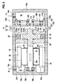
- Figs. 1 to 3 show an electric compressor of the first embodiment of the present invention.
- Fig. 1 is a cross section of the electric compressor
- Fig. 2 is a partially cross sectioned front view of a compressor body of the electric compressor
- Fig. 3 is an exploded perspective view of the electric compressor.
- the electric compressor of the first embodiment may be installed in a vehicular air conditioner of a refrigeration cycle, for example.
- fluid which is compressed by and discharged from the electric compressor is a refrigerant circulating in the refrigeration cycle.
- the electric compressor 10 includes a housing 11, a compressor body 20 and an electric motor 30 which are accommodated in the housing 11.
- the compressor body 20 is configured to suck, compress, and discharge a refrigerant.
- the electric motor 30 is configured to drive the compressor body 20.
- the electric motor 30 includes a cylinder-shaped stator 31 and a rotor 32 rotatably installed in the stator 31. From the center of the rotor 32 of the electric motor 30, a drive shaft 33 extends.
- the housing 11 includes a container-shaped first housing member 12 and a container-shaped second housing member 13 both having flanges 12F, 13F around those openings.
- the first housing member 12 and the second housing member 13 are combined to each other in a manner that the flanges 12F and 13F are fastened to each other to form the housing which has a closed box shape.
- the inside space of the housing 11 is divided, by the compressor body 20, into a suction chamber 14 shown on the right side of the compressor body 20 in Fig. 1 and a discharge chamber 14 shown on the left side of the compressor body 20 in Fig. 1 .
- the electric motor 30 is disposed in the suction chamber 14.
- the first housing member 12 is formed, at the vicinity of a side wall 12a thereof, with a suction port 14a for introducing a low pressured refrigerant into the suction chamber 14 from the outside (refrigerant inlet pipe).
- the second housing member 13 is formed, at the vicinity of a side wall 13a thereof, with an outlet port 15a for discharging a refrigerant compressed by and discharged from the compressor body 20 to the outside (refrigerant outlet pipe) from the discharge chamber 14.
- the compressor body 20 of this embodiment is composed as a rotary-type compressor body having vanes.
- the compressor body 20 includes a cylinder block 22 formed with a cylinder bore 21 which has a smooth noncircular sectioned inner circumferential surface as shown in Fig.
- vanes 24 projectably provided in the rotor 23, spaced out from each other along the outer circumferential surface and having a tip slidably contacting with the inner circumferential surface of the cylinder bore 21, and a suction side block 25 and a discharge side block 26 jointed to axial ends of the cylinder block 22, covering axial ends of the cylinder bore 21 and slidably contacting with the rotor 23.
- the suction side block 25 is formed with a suction hole 25a connecting the suction chamber 14 and the cylinder bore 21.
- the cylinder block 22 is formed with a discharge hole 22a
- the discharge side block 26 is formed with a discharge hole 26a, such that the cylinder bore 21 and the discharge chamber 14 are connected to each other via the discharge holes 22a and 26a.
- the stator 31 of the electric motor 30, as shown in Fig. 1 is fixed in the inner circumferential surface of the first housing member 12.
- the stator 31 is formed with coils 31a spaced out from each other in the circumferential direction. When the coils 31a of the stator 31 are energized to generalize the stator 31, the rotor 32 rotates.
- the drive shaft 33 of the electric motor 30 is inserted in the center of the rotor 32 and locked in a rotational direction so that the rotor 32 of the electric motor rotates integrally with the drive shaft 33.
- One end 33a (the left end in the figure) of the drive shaft 33 is formed integrally with the compressor rotor 23 of the compressor body 20.
- the one end 33a of the drive shaft 33 is rotatably supported with the side blocks 25, 26 at bearing holes 27, 27a serving as bearing portions.
- the other end 33b (the right side in the figure) of the drive shaft 3 is rotatably supported at the inside of a boss 12b serving as a bearing portion by means of a bearing 28.
- the boss 12b has a tubular shape inwardly projecting from the side wall 12a of the first housing member 12.
- the bearing portions 27, 27a are supplied with lubricant oil that is accumulated in the bottom of the housing 11 via an oil supply passage (not shown).
- the drive shaft 33 of the electric motor 30 rotates with the rotor 23 of the compressor body 20.
- the rotation of the rotor 23 leads a volumetric change of the space defined by the inner circumferential surface of the cylinder bore 21, the outer circumferential surface of the rotor 23, and adjacent two vanes 24.
- a low-pressure refrigerant is sucked from the outside (an inlet pipe) into the suction chamber 14 through the suction port 14, and sucked into the cylinder bore 21 of the compressor body 20 through a suction hole 25a of the compressor body 20.
- the low-pressure refrigerant, which has been sucked into the cylinder bore 21, is compressed to be a high pressure refrigerant and discharged into the discharge chamber 14 through the discharge holes 22a, 26a.
- the high-pressure refrigerant, which has been discharged in the discharge chamber 14, is discharged into the outside (an outlet pipe) through the outlet port 15a.
- An inverter 100 for controlling the electric motor 30 is disposed in the suction chamber 14.
- the inverter 100 is formed in an annular shape (a doughnut shape).
- An outer circumferential portion 102 of the inverter 100 which is a connecting portion, is connected to the housing in a manner that the outer portion 102 of the inverter 100 is sandwiched between the flange 12F of the first housing member 12 and the flange 13F of the second housing member 13.
- the inner portion 101 other than the connecting portion is a cooled portion 101.
- the inverter 100 includes circuit boards 116, 117 serving as electronic components having an inverter circuit with a switching element for driving the electric motor 3, and an inverter case 110 in which the circuit boards 116, 117 are accommodated.
- the inverter case 110 is formed in an annular shape (a doughnuts shape). That is, the inverter case 110 is formed with an outer circumferential portion having circular shape along the inner circumferential surface of the housing 11, and a circular through hole 111 in the center portion thereof. The outer circumferential portion of the inverter case 110 serves as the connecting portion 101 to be attached to the housing 11.
- the inverter case 110 includes a case body 112 formed with an outer circumferential wall 112a and a bottom wall 112b and a lid 113 formed in circular plate shape for covering an opening of the case body 112.
- the bottom wall 112b of the case body 112 has a first annular portion 114 projected from an outer surface thereof (the opposite side of the lid 113) to be fit on an inner circumferential surface of the second housing member 13.
- the lid 113 has a second annular portion 115 projected from an outer surface thereof (the opposite side of the case body) to be fit on an inner circumferential surface of the first housing member 12.
- the bottom wall 112b of the case body 112 and the lid 113 each have the through hole 111 at the center thereof.
- the bottom wall 112b of the case body 112 is formed with an inner circumferential wall 112c defining the through hole 111.
- the inner circumferential wall 112c and the outer circumferential wall 112a have the substantially same height.
- the circuit boards 116, 117 are attached to the bottom wall 112b of the case body 112b and the lid 113 on the inside thereof by means of bolts 118, 118a.
- the first and second circuit boards 116, 117 are connected with each other by a wire.
- the first circuit board 116 is formed in a doughnut shape, which is fit onto the inside of the outer circumferential wall 112a and the outside of the inner circumferential wall 112c.
- the first circuit board 116 is fixed to the bottom wall 112b of the case body 112 by bolts 118 that are inserted through holes 116a formed in the first circuit board 116 and screwed to bosses 112d formed in the bottom wall 112b of the case body 112.
- the second circuit board 117 is also formed in a doughnut shape, which is fit onto the inside of the outer circumferential wall 112a and the outside of the inner circumferential wall 112c.
- the second circuit board 117 is fixed to the lid 113 by bolts 118a that are inserted through holes 117a formed in the second circuit board 117 and screwed to bosses (not shown) inwardly projected from the lid 113.
- Bolts 119 which are inserted to through holes 113a formed at an outer circumferential portion of the lid 113, are screwed to screw holes 112e formed at a top of the outer circumferential wall 112a.
- Bolts 120 which are inserted to through holes 113b formed at an inner circumferential portion of the lid 113, are screwed to screw holes 112f formed at a top of the inner circumferential wall 112.
- a gasket 121 provided between the inside of the lid 113 and the top of the inner circumferential wall 112c maintains airtightness in the inverter case 110. It is noted that the gasket 121 is formed with through holes 121a for the bolts 120.
- the outer circumferential portion 102 of the inverter case 110 serving as a connecting portion is disposed between the flange 12F of the first housing member 12 and the flange 13F of the second housing member 13, the first annular portion 114 of the case body 112 is fit on the inner circumferential surface of the second housing member 13, and the second annular portion 115 of the lid 113 is fit on the inner circumferential surface of the first housing member 12.
- O-rings 122, 122a which are provided between the first annular portion 114 and the second housing member 13 and between the second annular portion 115 and the first housing member 12, maintain airtightness in the housing 11.
- the flanges 12F, 13F are fastened each other by fasteners (not shown) as sandwiching the outer circumferential portion 102 of the inverter case 110.
- the inverter case 110 is disposed in the suction chamber 14 and disposed between the electric motor 30 disposed in the first housing member 12 and the compressor body 20.
- the drive shaft 33 connecting the electric motor 30 and the compressor body 20 is inserted through the center through hole 111 of the inverter case 110 with a space therebetween.
- the inverter 100 is provided between the suction port 14a serving as an inlet of the suction chamber 14 and the suction hole 25a of the compressor body 20 serving as an outlet of the suction chamber 14.
- a low-temperature and low-pressure refrigerant which has been sucked from the suction port 14a into the suction chamber 14, flows through a clearance within the electric motor 30, the space between the through hole 111 of the inverter case 110 and the drive shaft 33, and is introduced into the compressor body 20.
- the inverter 100 is disposed in the suction chamber 14. With this configuration, the inverter 100 is cooled down by the low-temperature refrigerant introduced into the suction chamber 14, and this improves the cooling efficiency for cooling the inverter 100. Also the provision of the inverter 100 in the suction chamber 14 brings about the efficiency use of space in the suction chamber 14, and this prevents the electric compressor 10 from upsizing.
- the air-cooling fan and the power source for the air cooling fan are not required and this minimizes energy consumption.
- the inverter has a safety thermistor therein, when temperature of the inverter 100 rises over a predetermined temperature, a safety mechanism stops the operation of the electric compressor 10.
- the present embodiment disposes the inverter case 110 in the suction chamber 14 to cool more than one side of the inverter case, to maintain the inside temperature of the inverter case 110 low, so that the frequency of the electric compressor suspension performed by the safety mechanism is reduced.
- the inverter 100 is provided with the inverter case 110 accommodating the inverter circuit therein.
- the inverter case 110 is cooled to cool the inverter circuit, while protecting the inverter circuit.
- the inverter 100 since a part of the inverter 100 (the outer circumferential portion 102, in this embodiment) is fixed to the housing 11, the other portions of the inverter 100 are to be a cooled portion 101, and therefore a wider area of the inverter 100 can be cooled.
- the entire outer circumferential portion 102 of the inverter case 110 is connected to the housing 11, and this improves the stability of the attachment of the inverter case 110.
- a part of the inverter 100 (the outer circumferential portion 102 in this embodiment) is held between the flanges 12F, 1 3F of the housings 12, 13 to be attached to the housing 11.
- the inverter is attached to the housing 11 at the same time. This can make the assembly of the electric compressor 10 more efficient, thereby improving the productivity.
- the inverter case 110 is formed with the through hole 111, and therefore, the inner circumferential surface of the through hole 111 is exposed to refrigerant in the suction chamber 14 as well as the both sides of the inverter case 110.
- This configuration increases the cooled area on the inverter case 110 and improves the cooling efficiency for cooling the inverter 100.
- the inverter case 110 is formed with the through hole 111 at the center thereof, and therefore, the through hole 111 allows the drive shaft 33 of the electric motor 30 for driving the compressor body 20 to extend therethrough. This configuration improves the design flexibility and downsizes the electric compressor.
- the inverter case 110 is disposed between the suction port 14a serving as an inlet of the suction chamber 14 and the suction hole 25a of the compressor body 20 serving as an outlet of the suction chamber 14. This configuration causes the low-temperature refrigerant sucked from the suction port 14a to actively contact with the inverter case 110, thereby cooling the inverter 100 more efficiently.
- the low-temperature refrigerant which flows from the suction port 14a serving as the inlet of the suction chamber 14 to the outlet hole 25a of the compressor body 20 serving as the outlet of the suction chamber 14, is dammed by the inverter case 110 and forced to flow through the center through hole 111 of the inverter case 110.
- the electric motor 30 is accommodated in the housing 11 This simplifies the layout of the electric wire connecting the electric motor 30 and the inverter 100 controlling the electric motor 30.
- the electric motor 30 and the inverter 100 controlling the electric motor 30 are accommodated in the suction chamber 14. This configuration more simplifies the layout of the electric wire connecting the electric motor 30 and the inverter 100 controlling the electric motor 30.
- the inside space of the housing 11 is divided into the suction chamber 14 and the discharge chamber 15 by the compressor body 20. This simplifies the structure of the housing 11 and the manufacturing cost can be reduced.
- Fig. 4 shows a second embodiment of the present invention.
- the same reference numerals and symbols are used to designate the same elements as the elements described in the first embodiment, and redundant description thereof will be omitted.
- Fig. 4 is a cross sectional view of an electric compressor of the second embodiment.
- an inverter 100 of the electric compressor 10A of the second embodiment is fit onto an inner circumferential surface of a housing 11, and flanges 12F, 13F of first and second housings 12, 13 are directly connected with each other so that the inverter 100 is not sandwiched by the flanges 12F, 13F.
- the inverter 100 of the second embodiment is disposed closer to a suction port 14a than an electric motor 30.
- an outer circumferential surface of an inverter case 110 is abut on and fit in an inner circumferential surface of a first housing member 12.
- a lid 113 of the inverter case 110 is formed with a second annular portion 115, but a case body 112 of the inverter case 110 is formed without the first annular portion described in the first embodiment.
- O-rings 122, 122a are disposed between the an outer circumferential wall 112a of the case body 112 and the first housing member 12, and between the second annular portion 115 of the lid 113 and the first housing member 12.
- An outer circumferential edge of the lid 113 is abut on a step 12c formed on the inner circumferential surface of the first housing member 12 and location pins 123 are hammered into the first housing member 12 and the outer circumferential wall 112a of the case body.
- the electric compressor 10A of the second embodiment achieves the same effect as the first embodiment.
- the inverter 100 is disposed at an upstream side of the electric motor 30 in a stream of low-temperature refrigerant introduced into the suction chamber 14 from the suction port 14a. With this configuration, heat from the electric motor 30 does not effect to the inverter 100, thereby improving the efficiency for cooling the inverter 100.
- Fig. 5 shows a third embodiment of the present invention.
- the same reference numerals and symbols are used to designate the same elements as the elements described in the above embodiments, and redundant description thereof will be omitted.
- Fig. 5 is a cross sectional view of an electric compressor of the third embodiment.
- an inverter 100 is disposed around a boss 12b serving as a bearing portion for a drive shaft 33 of an electric motor 30. That is, the inverter 100 is disposed in a manner that the boss 12b extends through a through hole 111 of an inverter case 110.
- the inverter case 110 includes a case body 112 formed with an inner circumferential wall 112c, an outer circumferential wall 112a and a bottom wall 112b, and a lid 113 covering an opening end of the case body 112.
- First and second circuit boards 116, 117 are accommodated in and fixed to the inverter case 110, similar to the first embodiment.
- the third embodiment is arranged in a manner that the positions of the case body 112 and the lid 113 are switched.
- the inverter case 110 is abut on a side wall 12a of a first housing member 12 and fit on to an inner circumferential surface of the housing 11.
- the housing 11 and the inverter case 110 are fixed to each other in place by location pins 223.
- the suction port 14a is formed between the inverter case 110 and the electric motor 30.
- the inverter 100 are arranged in a manner that the boss 12b serving as a bearing portion for the drive shaft 33 are disposed through the through hole 111 of the inverter case 110. Therefore, the third embodiment is effective to downsize the housing 11 since the inverter 200 is placed at a dead space around the boss 12b of the housing 11, in addition to the same effects described in the first and second embodiments.
- Fig. 6 shows a fourth embodiment of the present invention.
- the same reference numerals and symbols are used to designate the same elements as the elements described in the above embodiments, and redundant description thereof will be omitted.
- Fig. 6 is a cross sectional view of an electric compressor of the fourth embodiment.
- a difference between the fourth embodiment and the second embodiment is that an electric motor 30 is disposed in a discharge chamber 14 in an electric compressor 10C of the fourth embodiment.
- a bottom of the discharge chamber 14 which is defined by the compressor body 20 is formed to be a lubricant oil tank for accumulating lubricant oil.
- the fourth embodiment is arranged in a manner that an inverter case 110 is disposed between a suction port 14a and a compressor body 20 and a drive shaft 33 does not extend through the center through hole 111 of the inverter case 110.
- a flow resistance in the through hole 111 is lower compared to a structure in which the drive shaft 33 extends through the through hole 111 of the inverter case 110.
- the electric motor 30 is disposed in the discharge chamber 14 in the electric compressor 10C of the fourth embodiment, a space between the electric motor 30 and an inner circumferential surface of the discharge chamber 14 can be used for an oil separator that separates lubricant oil from high-pressure refrigerant discharged from the discharge chamber 14. Therefore, another oil separator is not required and the electric compressor can be downsized.
- the present invention has been described above by reference to the first to fourth embodiments, the present invention is not limited to the embodiments. Modifications and variations of the embodiments can be made without departing from the spirit or scope of the present invention.
- the electric compressor is not limited to be used for a refrigeration cycle in a vehicular air conditioner.
- the compressor body is not limited to the vane-rotary-type compressor body, but can be an eccentric-roller-type rotary compressor body and any other non-rotary compressor body.
Applications Claiming Priority (3)
| Application Number | Priority Date | Filing Date | Title |
|---|---|---|---|
| JP2006136303A JP2007309110A (ja) | 2006-05-16 | 2006-05-16 | 電動コンプレッサ |
| JP2006136300A JP2007309109A (ja) | 2006-05-16 | 2006-05-16 | 電動コンプレッサ |
| PCT/JP2007/060022 WO2007132885A1 (ja) | 2006-05-16 | 2007-05-16 | 電動コンプレッサ |
Publications (1)
| Publication Number | Publication Date |
|---|---|
| EP2022984A1 true EP2022984A1 (de) | 2009-02-11 |
Family
ID=38693974
Family Applications (1)
| Application Number | Title | Priority Date | Filing Date |
|---|---|---|---|
| EP07743457A Withdrawn EP2022984A1 (de) | 2006-05-16 | 2007-05-16 | Elektrischer verdichter |
Country Status (3)
| Country | Link |
|---|---|
| US (1) | US20090269220A1 (de) |
| EP (1) | EP2022984A1 (de) |
| WO (1) | WO2007132885A1 (de) |
Cited By (1)
| Publication number | Priority date | Publication date | Assignee | Title |
|---|---|---|---|---|
| WO2013007278A1 (de) * | 2011-07-08 | 2013-01-17 | Pierburg Pump Technology Gmbh | Vakuumpumpe zum einsatz im kraftfahrzeugbereich |
Families Citing this family (6)
| Publication number | Priority date | Publication date | Assignee | Title |
|---|---|---|---|---|
| JP2009219268A (ja) * | 2008-03-11 | 2009-09-24 | Daikin Ind Ltd | 電力変換装置 |
| DE102008042656A1 (de) * | 2008-10-07 | 2010-04-15 | Ilmvac Gmbh | Elektromotor mit gekapseltem Motorgehäuse |
| JP5531186B2 (ja) * | 2008-12-18 | 2014-06-25 | サンデン株式会社 | 駆動回路一体型電動圧縮機 |
| US10208753B2 (en) | 2013-03-29 | 2019-02-19 | Agilent Technologies, Inc. | Thermal/noise management in a scroll pump |
| US9611852B2 (en) * | 2013-03-29 | 2017-04-04 | Agilent Technology, Inc. | Thermal/noise management in a scroll pump |
| JP6986422B2 (ja) * | 2017-11-14 | 2021-12-22 | 株式会社デンソーテン | 気体噴射装置および気体噴射システム |
Family Cites Families (5)
| Publication number | Priority date | Publication date | Assignee | Title |
|---|---|---|---|---|
| JP2002285980A (ja) * | 2001-03-26 | 2002-10-03 | Toyota Industries Corp | スクロール型圧縮機及びスクロール型圧縮機の潤滑方法 |
| JP4265229B2 (ja) * | 2003-01-29 | 2009-05-20 | ダイキン工業株式会社 | 回転式圧縮機 |
| JP4022163B2 (ja) * | 2003-03-27 | 2007-12-12 | 三菱重工業株式会社 | 電動圧縮機 |
| JP4200885B2 (ja) * | 2003-11-21 | 2008-12-24 | 株式会社デンソー | 電動圧縮機用モータ駆動装置 |
| JP2005171951A (ja) | 2003-12-15 | 2005-06-30 | Matsushita Electric Ind Co Ltd | 電動圧縮機 |
-
2007
- 2007-05-16 EP EP07743457A patent/EP2022984A1/de not_active Withdrawn
- 2007-05-16 WO PCT/JP2007/060022 patent/WO2007132885A1/ja active Application Filing
- 2007-05-16 US US12/300,925 patent/US20090269220A1/en not_active Abandoned
Non-Patent Citations (1)
| Title |
|---|
| See references of WO2007132885A1 * |
Cited By (1)
| Publication number | Priority date | Publication date | Assignee | Title |
|---|---|---|---|---|
| WO2013007278A1 (de) * | 2011-07-08 | 2013-01-17 | Pierburg Pump Technology Gmbh | Vakuumpumpe zum einsatz im kraftfahrzeugbereich |
Also Published As
| Publication number | Publication date |
|---|---|
| US20090269220A1 (en) | 2009-10-29 |
| WO2007132885A1 (ja) | 2007-11-22 |
Similar Documents
| Publication | Publication Date | Title |
|---|---|---|
| US8616014B2 (en) | Compressor having capacity modulation or fluid injection systems | |
| EP2022984A1 (de) | Elektrischer verdichter | |
| EP2484905B1 (de) | Elektrischer kompressor mit integriertem umrichter | |
| EP2072822B1 (de) | Motorbetriebener Verdichter | |
| US20050058564A1 (en) | Scroll-type fluid machine | |
| US11002278B2 (en) | Pump mechanism and horizontal compressor having same | |
| US6655172B2 (en) | Scroll compressor with vapor injection | |
| US11236748B2 (en) | Compressor having directed suction | |
| US20200392953A1 (en) | Compressor Having Suction Fitting | |
| JP2002285981A (ja) | スクロール型圧縮機およびスクロール型圧縮機の潤滑油供給方法 | |
| CN101443553A (zh) | 电动压缩机 | |
| JP2012132435A (ja) | 空気調和機 | |
| JP2002285982A (ja) | スクロール型圧縮機およびスクロール型圧縮機の潤滑油供給方法 | |
| US10634142B2 (en) | Compressor oil separation and assembly method | |
| US20020094289A1 (en) | Scroll-type compressor with cooling fins included inside a discharge port of a compressed gas | |
| JP2002295369A (ja) | 電動圧縮機および電動圧縮機の潤滑油循環方法 | |
| JP4238555B2 (ja) | スクロール圧縮機 | |
| KR20190135277A (ko) | 전동압축기 | |
| JP2007309110A (ja) | 電動コンプレッサ | |
| JP2563591B2 (ja) | スクロール圧縮機 | |
| CN111749899B (zh) | 具有油配给构件的压缩机 | |
| JP5906378B2 (ja) | 電動圧縮機 | |
| KR20230042358A (ko) | 쉘 피팅을 구비하는 압축기 | |
| JP2012047140A (ja) | 電動圧縮機 | |
| CN117545920A (zh) | 电动压缩机 |
Legal Events
| Date | Code | Title | Description |
|---|---|---|---|
| PUAI | Public reference made under article 153(3) epc to a published international application that has entered the european phase |
Free format text: ORIGINAL CODE: 0009012 |
|
| 17P | Request for examination filed |
Effective date: 20081209 |
|
| AK | Designated contracting states |
Kind code of ref document: A1 Designated state(s): AT BE BG CH CY CZ DE DK EE ES FI FR GB GR HU IE IS IT LI LT LU LV MC MT NL PL PT RO SE SI SK TR |
|
| AX | Request for extension of the european patent |
Extension state: AL BA HR MK RS |
|
| DAX | Request for extension of the european patent (deleted) | ||
| RBV | Designated contracting states (corrected) |
Designated state(s): DE FR GB |
|
| STAA | Information on the status of an ep patent application or granted ep patent |
Free format text: STATUS: THE APPLICATION HAS BEEN WITHDRAWN |
|
| 18W | Application withdrawn |
Effective date: 20100330 |