EP2022423B1 - Dispositif d'ancrage d'os - Google Patents
Dispositif d'ancrage d'os Download PDFInfo
- Publication number
- EP2022423B1 EP2022423B1 EP07015041A EP07015041A EP2022423B1 EP 2022423 B1 EP2022423 B1 EP 2022423B1 EP 07015041 A EP07015041 A EP 07015041A EP 07015041 A EP07015041 A EP 07015041A EP 2022423 B1 EP2022423 B1 EP 2022423B1
- Authority
- EP
- European Patent Office
- Prior art keywords
- bone anchoring
- head
- anchoring device
- locking ring
- receiving part
- Prior art date
- Legal status (The legal status is an assumption and is not a legal conclusion. Google has not performed a legal analysis and makes no representation as to the accuracy of the status listed.)
- Active
Links
- 210000000988 bone and bone Anatomy 0.000 title claims description 96
- 238000004873 anchoring Methods 0.000 title claims description 78
- 230000008878 coupling Effects 0.000 claims description 9
- 238000010168 coupling process Methods 0.000 claims description 9
- 238000005859 coupling reaction Methods 0.000 claims description 9
- 230000006835 compression Effects 0.000 claims description 3
- 238000007906 compression Methods 0.000 claims description 3
- 230000004308 accommodation Effects 0.000 description 4
- 239000000463 material Substances 0.000 description 4
- 230000004048 modification Effects 0.000 description 4
- 238000012986 modification Methods 0.000 description 4
- 238000001356 surgical procedure Methods 0.000 description 4
- 230000000052 comparative effect Effects 0.000 description 2
- 230000000694 effects Effects 0.000 description 2
- 229910001200 Ferrotitanium Inorganic materials 0.000 description 1
- RTAQQCXQSZGOHL-UHFFFAOYSA-N Titanium Chemical compound [Ti] RTAQQCXQSZGOHL-UHFFFAOYSA-N 0.000 description 1
- 239000000560 biocompatible material Substances 0.000 description 1
- 238000005520 cutting process Methods 0.000 description 1
- 230000001419 dependent effect Effects 0.000 description 1
- 238000011161 development Methods 0.000 description 1
- 230000018109 developmental process Effects 0.000 description 1
- 230000003100 immobilizing effect Effects 0.000 description 1
- 208000014674 injury Diseases 0.000 description 1
- 238000004519 manufacturing process Methods 0.000 description 1
- 238000003825 pressing Methods 0.000 description 1
- 238000007788 roughening Methods 0.000 description 1
- 229910001285 shape-memory alloy Inorganic materials 0.000 description 1
- 239000010935 stainless steel Substances 0.000 description 1
- 229910001220 stainless steel Inorganic materials 0.000 description 1
- 239000010936 titanium Substances 0.000 description 1
- 230000008733 trauma Effects 0.000 description 1
Images


Classifications
-
- A—HUMAN NECESSITIES
- A61—MEDICAL OR VETERINARY SCIENCE; HYGIENE
- A61B—DIAGNOSIS; SURGERY; IDENTIFICATION
- A61B17/00—Surgical instruments, devices or methods, e.g. tourniquets
- A61B17/56—Surgical instruments or methods for treatment of bones or joints; Devices specially adapted therefor
- A61B17/58—Surgical instruments or methods for treatment of bones or joints; Devices specially adapted therefor for osteosynthesis, e.g. bone plates, screws, setting implements or the like
- A61B17/68—Internal fixation devices, including fasteners and spinal fixators, even if a part thereof projects from the skin
- A61B17/70—Spinal positioners or stabilisers ; Bone stabilisers comprising fluid filler in an implant
- A61B17/7001—Screws or hooks combined with longitudinal elements which do not contact vertebrae
- A61B17/7035—Screws or hooks, wherein a rod-clamping part and a bone-anchoring part can pivot relative to each other
- A61B17/7037—Screws or hooks, wherein a rod-clamping part and a bone-anchoring part can pivot relative to each other wherein pivoting is blocked when the rod is clamped
-
- A—HUMAN NECESSITIES
- A61—MEDICAL OR VETERINARY SCIENCE; HYGIENE
- A61B—DIAGNOSIS; SURGERY; IDENTIFICATION
- A61B17/00—Surgical instruments, devices or methods, e.g. tourniquets
- A61B17/56—Surgical instruments or methods for treatment of bones or joints; Devices specially adapted therefor
- A61B17/58—Surgical instruments or methods for treatment of bones or joints; Devices specially adapted therefor for osteosynthesis, e.g. bone plates, screws, setting implements or the like
- A61B17/60—Surgical instruments or methods for treatment of bones or joints; Devices specially adapted therefor for osteosynthesis, e.g. bone plates, screws, setting implements or the like for external osteosynthesis, e.g. distractors, contractors
-
- A—HUMAN NECESSITIES
- A61—MEDICAL OR VETERINARY SCIENCE; HYGIENE
- A61B—DIAGNOSIS; SURGERY; IDENTIFICATION
- A61B17/00—Surgical instruments, devices or methods, e.g. tourniquets
- A61B17/56—Surgical instruments or methods for treatment of bones or joints; Devices specially adapted therefor
- A61B17/58—Surgical instruments or methods for treatment of bones or joints; Devices specially adapted therefor for osteosynthesis, e.g. bone plates, screws, setting implements or the like
- A61B17/68—Internal fixation devices, including fasteners and spinal fixators, even if a part thereof projects from the skin
- A61B17/70—Spinal positioners or stabilisers ; Bone stabilisers comprising fluid filler in an implant
- A61B17/7001—Screws or hooks combined with longitudinal elements which do not contact vertebrae
- A61B17/7032—Screws or hooks with U-shaped head or back through which longitudinal rods pass
- A61B17/7034—Screws or hooks with U-shaped head or back through which longitudinal rods pass characterised by a lateral opening
-
- A—HUMAN NECESSITIES
- A61—MEDICAL OR VETERINARY SCIENCE; HYGIENE
- A61B—DIAGNOSIS; SURGERY; IDENTIFICATION
- A61B17/00—Surgical instruments, devices or methods, e.g. tourniquets
- A61B17/56—Surgical instruments or methods for treatment of bones or joints; Devices specially adapted therefor
- A61B17/58—Surgical instruments or methods for treatment of bones or joints; Devices specially adapted therefor for osteosynthesis, e.g. bone plates, screws, setting implements or the like
- A61B17/68—Internal fixation devices, including fasteners and spinal fixators, even if a part thereof projects from the skin
- A61B17/70—Spinal positioners or stabilisers ; Bone stabilisers comprising fluid filler in an implant
- A61B17/7001—Screws or hooks combined with longitudinal elements which do not contact vertebrae
- A61B17/7032—Screws or hooks with U-shaped head or back through which longitudinal rods pass
Definitions
- the invention relates to a bone anchoring device comprising a bone anchoring element and a receiving part for connection to a rod.
- the head of the bone anchoring element is locked in the receiving part by compression of a portion of the receiving part laterally surrounding the head by means of a locking ring which is pressed down by the rod.
- the portion of the receiving part which clamps the head is designed so as to allow the locking ring to be mounted from the free end of the portion.
- the bone anchoring device can be realized, for example, in form of a polyaxial bone screw allowing a pivotal movement of the head or in form of a monoaxial bone screw allowing a rotational movement of the head around a single axis in the unlocked state, respectively.
- DE 43 05 576 C1 describes a polyaxial bone screw having a screw element and a receiving part and a pressure element acting onto the head of the screw element to press it down against the seat in the receiving part in order to lock the rotational position of the head.
- the bone screw usually is preassembled so that the screw element is screwed into the bone with the receiving part mounted on the screw element.
- EP 0 242 708 A2 describes a bone screw with a receiving part consisting of two spherically-shaped halves pressing from two lateral sides onto the spherical head. The halves are held together in their lower portion by a ring.
- US 5,672,179 discloses a bone screw with a receiving part with a conically shaped seat and a conically-shaped pressure element which exerts pressure onto the head from above and from the side. If the cone angle has a value lying within a specific range self-locking of the pressure element within the receiving part takes place which allows to preliminary lock the head within the receiving part while the rod is still moveable in order to allow the adjustment of its position.
- EP 0 951 245 B1 describes a bone screw with a receiving part having a conically-shaped cavity accommodating the head wherein a spring chuck is provided in the cavity which is downwardly and radially compressible to clamp the head.
- US 5,728,098 discloses a bone screw for connection to a spinal rod comprising a screw element and a receiver member which has slits provided at the bottom of the rod receiving channel and wherein two locking rings made of a shape memory alloy are provided one at the lower side of the receiver member and one of the upper side. The locking rings contract about the portions of the receiver member when the temperature is elevated so that the rod is clamped in the channel.
- US 5,549,608 discloses a polyaxial bone screw with a screw element with a spherical head and a coupling element to couple the screw element to a spinal rod.
- the coupling element has a tapered lower portion including a slotted interior chamber in which the spherical head is initially polyaxially disposed.
- the coupling element further comprises a recess for receiving the head.
- a locking ring surrounding the lower portion of the coupling element and a cylindrical rod securing sleeve which fits over the coupling element are provided.
- a locking nut is used to exert pressure onto the rod securing sleeve.
- the head is locked in the interior chamber by means of the locking ring which is pressed down by the rod securing sleeve.
- US 5,575,792 discloses a similar device using a hook instead of a bone screw.
- the rod securing sleeve is omitted and the rod directly presses onto the locking ring.
- the locking ring has to be placed onto the coupling element from above. It is not secured against escaping towards the upper end and against rotation when the rod is not inserted.
- the size of this known bone anchoring device is quite large as the locking ring and the locking nut extend substantially outward from the diameter of the coupling element.
- WO 2007/038350 A2 discloses a generic bone anchoring device comprising a bone anchoring element having a shaft for anchoring in the bone and a head; a receiving part for coupling a rod to the bone anchoring element, wherein the receiving part comprises a first portion with a first end and a second end and a U-shaped recess for receiving the rod, the recess extending from the first end in the direction of the second end thereby forming two free legs and a second portion at the side of the second end opposite to the first end for accommodating the head, the second portion having a free end and being flexible so as to allow introduction and clamping of the head; a locking ring embracing the second portion; wherein the head is locked by means of exerting pressure with the rod onto the locking ring resulting in compression of the second portion of the receiving part and wherein the locking ring is mounted to the receiving part from the free end of the second portion.
- Another bone anchoring device is known from US 2005/080415 A1 .
- the bone anchoring device comprises only few elements which reduces the costs of manufacturing and facilitates handling. It makes use of the principle of clamping the head of the bone anchoring element circumferentially from the lateral sides which reduces the force necessary to safely clamp the head.
- the design of the bone anchoring device allows to further reduce the dimension in terms of height as well as in terms of the diameter which makes it particularly suitable for applications where small-sized anchoring devices are required such as in the field of cervical spine surgery or pediatric applications, trauma and minimal open applications for bone surgery.
- the receiving part can be clicked onto the head of the bone anchoring element at any time before and during surgery. Therefore, it is for example possible to first anchor the bone anchoring element in the bone and thereafter connect it to the receiving part and the rod.
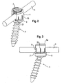
- the bone anchoring device comprises a bone anchoring element 1 in the form of a bone screw having a threaded shaft 2 and a spherical segment-shaped head 3.
- the head 3 has a recess 4 for engagement with a screwing-in tool.
- the bone anchoring device further comprises a receiving part 5 for receiving a rod 6 to connect it to the bone anchoring element 1.
- a closure element 7 in form of an inner screw or set screw is provided for securing the rod 6 in the receiving part 5.
- the bone anchoring device comprises a locking ring 8 for locking the head in the receiving part 5.
- the receiving part 5 comprises a first portion 9 which is substantially cylindrical and which has first end 9a and an opposite second end 9b.
- the first portion 9 has a coaxial first bore 10 provided at the second end 9b.
- the diameter of the first bore 10 is smaller than the diameter of the head 3 of the bone anchoring element.
- the first portion 9 also comprises a coaxial second bore 11 extending from the first end 9a to a distance from the second end 9b.
- the diameter of the second bore 11 is larger than that of the first bore 10 and larger than the diameter of the rod 6.
- a U-shaped recess 12 is provided in the first portion which extends from the first end 9a to the second end 9b the diameter of the U-shaped recess being slightly larger than the diameter of the rod 6 in such a way that the rod 6 can be placed in the recess and is guided therein.
- the internal thread can be a metric thread, a flat thread, a negative angle thread, a saw-tooth thread or any other thread.
- a thread form such as a flat thread or a negative angle thread is used which prevents splaying of the legs 12a, 12b when the inner screw 7 is screwed-in.
- the depth of the U-shaped recess is such that the rod 6 and the inner screw 7 can be inserted between the legs.
- a flat section 14 is provide forming the end of the bore 11.
- the first portion 9 of the receiving part 5 further comprises a plurality of coaxial slits 15 extending from the second end 9b to a distance from the first end wherein the distance corresponds approximately to the length of the internal thread 13.
- the slits 15 are open at the second end 9b and extend, as can be seen in particular in Figs. 6, 9 and 10 through the flat section 14 and the U-shaped recess 12.
- At least one slit 15, preferably more than one slit is provided on either side of the U-shaped recess.
- the number of slits is selected according to the degree of elasticity which shall be provided by the slits. It may depend on the material and the wall thickness and/or other factors.
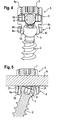
- the receiving part 5 Adjacent to the second end 9b the receiving part 5 comprises a second portion 16 providing an accommodation space for the head 3 of the bone anchoring element 1.
- the second portion 16 has a conically-shaped outer surface including a cone angle ⁇ which tapers towards the second end 9b and which has a free end 17 opposite to the second end 9b.
- the outer diameter of the first portion 9 at its second end 9b is larger than the outer diameter of the second portion 16 adjacent to the second end 9b and also larger than the outer diameter of the second portion at its free end 17.
- the second portion 16 is recessed with respect to the first portion 9.
- the second portion 16 has an internal hollow spherical section 18 forming a seat for the spherical segment-shaped head 3 of the bone anchoring element 1.
- the hollow spherical section 18 is dimensioned in such a way that it encompasses the head 3 of the bone anchoring element from the side covering a region including the largest diameter of the head 3.
- 6 cut 24 are provided in the first portion on either end of the channel formed by the recess 12.
- a plurality of slits 19 are provided which are open to the free end 17 and extend from the free end 17 to the second end 9b of the first portion and continue in the slits 15 of the first portion thereby forming a continuous slit extending from the free end 17 of the second portion into the first portion.
- the number of slits 19 may be equal to the number of the slits 15, however, it can be smaller or larger depending on the desired elasticity of the second portion 16.
- slits 20 are provided on the side of the second portion 16 which is adjacent to the U-shaped recess 12 of the first portion. The slits 20 end at a distance of the second end 9b.
- the elasticity of the second portion 16 is such that the head 3 of the anchoring element can be inserted by expanding the second portion and can be clamped by compressing the second portion.
- the slits 15 in the first portion facilitate mounting of the receiving part onto the head 3 manually, for example at any time before or during surgery.
- the elasticity of the second portion 16 and the size of the second portion at the free end 17 allows to mount the locking ring by clicking it from the free end 17 onto the second portion 16. Since the outer diameter of the second portion is smaller than that of the first portion 9, the locking ring does not project beyond the first portion in a radial direction.
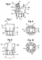
- the locking ring 8 has on its inner side a first section 8a and adjacent thereto a second section 8b.
- the first section 8a is conically-shaped corresponding to the conical outer wall of the second portion 16 of the receiving part 5.
- the first section 8b is cylindrical.
- the dimensions of the first section 8a and the second section 8b of the locking ring are such that the locking ring 8 can slide along the outer surface of the second portion 16 and thereby compressing the second portion 16 increasingly when sliding downward.
- the locking ring is movable between a first position limited by the second end 9b which acts as a stop and the free end 17 of the second portion which prevents escaping due to the conical shape.
- the cone angle ⁇ is selected to be between approximately 2° and 10°, a self-locking can be achieved between the locking ring and the second portion which means that an additional force would be required to loosen the locking ring once it has clamped the head 3. If the cone angle ⁇ is larger than approximately 10°, no self-locking effect is present.
- the angles at which a self-locking effect can be achieved depend on the materials used and the treatment of the surfaces engaging each other.
- the locking ring 8 further comprises on its side facing the second end 9b two projections 21 located diametrically opposite to each other.
- the projections 21 have a such height that they project above the bottom of the U-shaped recess 12 and extend into the cuts 24 when the locking ring is in a position in which the head 3 is not yet clamped.
- the free end 22 of the projections 21 can be curved with a curvature corresponding to that of the rod 6.
- the locking ring is arranged in such a way around the second portion 16 of the receiving part 5 that the projections 21 are located at the positions of the U-shaped recess 12. By means of this, the projections 21 which project into the U-shaped recess 12 prevent the locking ring from rotating when the rod is not inserted.
- the inner screw 7 has a thread cooperating with the internal thread 13 provided on the legs. If a thread form which prevents the legs from splaying is used, a single closure element such as the inner screw 7 is sufficient. This reduces the size of the bone anchoring device in a radial direction.
- the receiving part, the locking ring, the inner screw and the bone anchoring element are made of a biocompatible material, for example of titanium or stainless steel or a biocompatible plastic material with sufficient strength.
- the bone anchoring device may be preassembled with the locking ring which is mounted on the second portion 16 of the receiving part 5 from the free end 17.
- the bone anchoring element 1 can be preassembled with the receiving part 5 and the locking ring 8.
- the locking ring 8 When the locking ring 8 is moved toward the free end 17 of the second portion, it compresses the second portion 16 thereby clamping the head 3. Since the force which is exerted by the locking ring acts from the lateral side, the force necessary for safely immobilizing the head is smaller than in the case in which the force acts from above on the top of the head 3. This also allows to downsize the device by allowing the wall thickness of the receiving part to be reduced.
- the receiving part 5 and the locking ring 8 are preassembled.
- the bone anchoring element 3 is first screwed into the bone and then the receiving part is clicked onto the head 3 while the locking ring 8 is in its first position close to the second end 9b and does not compress the second portion 16.
- the bone anchoring element 1 and the receiving part with preassembled locking ring are assembled by the surgeon by clicking the receiving part onto the head 3. This allows the surgeon to select the appropriate bone anchoring element in terms of diameter and length of the anchoring section.
- the head can be locked independently of the rod, if, as descibed above, the cooperating surfaces of the locking ring and the second portion are designed so as to allow a preliminary fixation.
- Figs. 11 to 13 show a second embodiment of the bone anchoring device. Portions and elements which are identical to the first embodiment are designated with the same reference numerals as in the description of the first embodiment. The description thereof will not be repeated.
- the receiving part 5 cannot pivot relative to the bone anchoring element 1' but can only rotate in the unclamped state of the head 30.
- Such a monoaxial rotatable connection between the receiving part 5 and the bone anchoring element 1' may be useful in certain anatomical situations. It allows the receiving part to be aligned with respect to the rod by only rotating it around the screw axis.
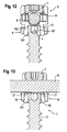
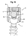
- Figs. 14 and 15 show a third embodiment of the bone anchoring device. Portions and elements which are identical to the first embodiment are designated with the same reference numerals as in the description of the previous embodiments and the detailed description thereof will not be repeated.
- the receiving part 5 of the third embodiment comprises an inclined free edge 17' of the second portion 16. As can be seen in particular in Fig. 14 , the inclined free end 17' defines a plane which includes an angle with the plane defined by the first end 9a of the first portion of the receiving part.
- the hollow spherical section 18' which accommodates the head 3 is therefore shorter on one side compared to the opposite side.
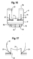
- Figs. 16 and 17 show a modification of the locking ring.
- the receiving part 5 is identical to one of the previously described receiving parts and the description thereof will not be repeated.
- the locking ring 8' has on either side of each projection 21 a lateral projection 23 resulting in a diameter of the projection 21 which is larger than the diameter of the cuts 24 on the basis of recess 12.
- the projections 23 snap into the recess 12 due to the elasticity of the receiving part 5.
- the projections 23 form a securing means against falling off of the locking ring 8' when the head 3 is not yet inserted. This may be useful when the surgeon handles the parts before the receiving part 5 is clicked onto the screw.
Landscapes
- Health & Medical Sciences (AREA)
- Orthopedic Medicine & Surgery (AREA)
- Life Sciences & Earth Sciences (AREA)
- Surgery (AREA)
- Neurology (AREA)
- Heart & Thoracic Surgery (AREA)
- Engineering & Computer Science (AREA)
- Biomedical Technology (AREA)
- Nuclear Medicine, Radiotherapy & Molecular Imaging (AREA)
- Medical Informatics (AREA)
- Molecular Biology (AREA)
- Animal Behavior & Ethology (AREA)
- General Health & Medical Sciences (AREA)
- Public Health (AREA)
- Veterinary Medicine (AREA)
- Surgical Instruments (AREA)
- Prostheses (AREA)
Claims (14)
- Dispositif d'ancrage osseux comprenant:un élément (1, 1') d'ancrage osseux ayant un arbre (2) à ancrer dans l'os et une tête (3, 3');une partie de réception (5) pour accoupler une tige (6) à l'élément d'ancrage osseux, où la partie de réception comprendune première partie (9) avec une première extrémité (9a) et une deuxième extrémité (9b) et une cavité (12) en forme de U pour recevoir la tige, la cavité (12) ayant un fond et s'étendant de la première extrémité (9a) en direction de la deuxième extrémité (9b) formant ainsi deux jambes libres (12a, 12b) etune deuxième partie (16) au côté de la deuxième extrémité (9b) opposée à la première extrémité pour accueillir la tête (3, 3'), la deuxième partie ayant une extrémité libre (17) et étant flexible de sorte à permettre l'introduction et le serrage de la tête;un anneau de verrouillage (8) encerclant la deuxième partie (16); où la tête (3, 3') est verrouillée au moyen d'une pression exercée avec la tige sur l'anneau de verrouillage (8) résultant en la compression de la deuxième partie de la partie de réception et où l'anneau de verrouillage (8) est monté sur la partie de réception depuis l'extrémité libre (17) de la deuxième partie (16),caractérisé en ce quela cavité (12) en forme de U comprend une découpe (24) sur chaque extrémité du fond et en ce que l'anneau de verrouillage (8) comprend deux projections placées de manière diamétralement opposée l'une par rapport à l'autre et ayant une hauteur telles qu'elles se projettent au-dessus du fond de la cavité en forme de U et s'étendent dans les découpes (24), respectivement, lorsque l'anneau de verrouillage se trouve dans une position où la tête (3, 3') n'est pas encore verrouillée.
- Dispositif d'ancrage osseux selon la revendication 1, dans lequel, le diamètre de la deuxième partie (16) de la partie de réception (5) adjacente à la deuxième extrémité est plus petit que le diamètre de la première partie (9) à la deuxième extrémité (9b).
- Dispositif d'ancrage osseux selon la revendication 1 ou 2, dans lequel l'anneau de verrouillage (8) se déplace le long de la deuxième partie entre une première position limitée par la deuxième extrémité (9b) de la première partie (9) et une deuxième position limitée par l'extrémité libre (17) de la deuxième partie (16) lorsque la tête n'est pas serrée.
- Dispositif d'ancrage osseux selon l'une des revendications 1 à 3, dans lequel le diamètre externe de l'anneau de verrouillage (8) est inférieur ou égal au diamètre externe de la première partie (9).
- Dispositif d'ancrage osseux selon l'une des revendications 1 à 4, dans lequel la deuxième partie (16) de la partie de réception a une surface externe conique s'effilant vers la deuxième extrémité (9b).
- Dispositif d'ancrage osseux selon la revendication 5, dans lequel l'anneau de verrouillage a une section (8a) avec une surface interne s'effilant de manière conique correspondant à la surface externe conique de la deuxième partie (16).
- Dispositif d'ancrage osseux selon la revendication 6, dans lequel l'angle de cône (α) est sélectionné pour fournir un auto-verrouillage entre l'anneau de verrouillage (8) et la deuxième partie (16).
- Dispositif d'ancrage osseux selon l'une des revendications 1 à 7, dans lequel la deuxième partie (16) comprend une pluralité de fentes (19, 20) qui s'ouvrent sur l'extrémité libre (17).
- Dispositif d'ancrage osseux selon l'une des revendications 1 à 8, dans lequel la première partie (9) comprend une pluralité de fentes (15) s'étendant sur une distance de la première extrémité (9a) à la deuxième extrémité (9b).
- Dispositif d'ancrage osseux selon l'une des revendications 1 à 9, dans lequel la tête (3) est sous forme de segment sphérique et la deuxième partie comprend une surface interne avec une partie sphérique correspondante (18) pour permettre un mouvement de pivotement de la tête (3).
- Dispositif d'ancrage osseux selon l'une des revendications 1 à 9, dans lequel la tête (3') est de forme cylindrique et la deuxième partie comprend une surface interne avec une partie cylindrique correspondante (181) pour limiter le mouvement de la tête (3') à un mouvement rotatif autour d'un axe unique.
- Dispositif d'ancrage osseux selon l'une des revendications 1 à 11, dans lequel un élément de fermeture (7), de préférence une vis de pression, est fourni pour fixer la tige dans la cavité.
- Dispositif d'ancrage osseux selon l'une des revendications 1 à 9, dans lequel un plan passant à travers l'extrémité libre (17) de la deuxième partie (16) comporte un angle avec la première extrémité (9a).
- Dispositif d'ancrage osseux selon l'une des revendications 1 à 13, dans lequel l'anneau de verrouillage a une structure (23) l'empêchant de sortir de l'extrémité libre (17) lorsque la tête (3) n'est pas encore insérée dans la deuxième partie (16).
Priority Applications (18)
| Application Number | Priority Date | Filing Date | Title |
|---|---|---|---|
| DE602007007758T DE602007007758D1 (de) | 2007-07-31 | 2007-07-31 | Knochenverankerungsvorrichtung |
| EP07015041A EP2022423B1 (fr) | 2007-07-31 | 2007-07-31 | Dispositif d'ancrage d'os |
| ES07015041T ES2348814T3 (es) | 2007-07-31 | 2007-07-31 | Dispositivo de anclaje ã“seo. |
| CN2008101311178A CN101357073B (zh) | 2007-07-31 | 2008-07-28 | 骨头锚固装置 |
| JP2008193438A JP5415722B2 (ja) | 2007-07-31 | 2008-07-28 | 骨固定装置 |
| KR20080073783A KR101496311B1 (ko) | 2007-07-31 | 2008-07-28 | 뼈 고정 장치 |
| TW097128542A TWI441614B (zh) | 2007-07-31 | 2008-07-29 | 骨骼固定裝置 |
| ES10196877T ES2424338T3 (es) | 2007-07-31 | 2008-07-31 | Dispositivo de anclaje óseo |
| EP08013775A EP2022424B1 (fr) | 2007-07-31 | 2008-07-31 | Dispositif d'ancrage d'os |
| DE602008004191T DE602008004191D1 (de) | 2007-07-31 | 2008-07-31 | Knochenverankerungsvorrichtung |
| ES08013775T ES2358955T3 (es) | 2007-07-31 | 2008-07-31 | Dispositivo de anclaje óseo. |
| ES10195927.8T ES2527215T3 (es) | 2007-07-31 | 2008-07-31 | Dispositivo de anclaje óseo |
| EP10195927.8A EP2301457B1 (fr) | 2007-07-31 | 2008-07-31 | Dispositif d'ancrage d'os |
| US12/183,932 US8192470B2 (en) | 2007-07-31 | 2008-07-31 | Bone anchoring device |
| EP10196877.4A EP2311396B1 (fr) | 2007-07-31 | 2008-07-31 | Dispositif d'ancrage d'os |
| US13/466,773 US8940024B2 (en) | 2007-07-31 | 2012-05-08 | Bone anchoring device |
| JP2013235739A JP2014079628A (ja) | 2007-07-31 | 2013-11-14 | 骨固定装置 |
| US14/584,287 US9289246B2 (en) | 2007-07-31 | 2014-12-29 | Bone anchoring device |
Applications Claiming Priority (1)
| Application Number | Priority Date | Filing Date | Title |
|---|---|---|---|
| EP07015041A EP2022423B1 (fr) | 2007-07-31 | 2007-07-31 | Dispositif d'ancrage d'os |
Publications (2)
| Publication Number | Publication Date |
|---|---|
| EP2022423A1 EP2022423A1 (fr) | 2009-02-11 |
| EP2022423B1 true EP2022423B1 (fr) | 2010-07-14 |
Family
ID=39048828
Family Applications (4)
| Application Number | Title | Priority Date | Filing Date |
|---|---|---|---|
| EP07015041A Active EP2022423B1 (fr) | 2007-07-31 | 2007-07-31 | Dispositif d'ancrage d'os |
| EP10195927.8A Active EP2301457B1 (fr) | 2007-07-31 | 2008-07-31 | Dispositif d'ancrage d'os |
| EP10196877.4A Active EP2311396B1 (fr) | 2007-07-31 | 2008-07-31 | Dispositif d'ancrage d'os |
| EP08013775A Active EP2022424B1 (fr) | 2007-07-31 | 2008-07-31 | Dispositif d'ancrage d'os |
Family Applications After (3)
| Application Number | Title | Priority Date | Filing Date |
|---|---|---|---|
| EP10195927.8A Active EP2301457B1 (fr) | 2007-07-31 | 2008-07-31 | Dispositif d'ancrage d'os |
| EP10196877.4A Active EP2311396B1 (fr) | 2007-07-31 | 2008-07-31 | Dispositif d'ancrage d'os |
| EP08013775A Active EP2022424B1 (fr) | 2007-07-31 | 2008-07-31 | Dispositif d'ancrage d'os |
Country Status (8)
| Country | Link |
|---|---|
| US (3) | US8192470B2 (fr) |
| EP (4) | EP2022423B1 (fr) |
| JP (2) | JP5415722B2 (fr) |
| KR (1) | KR101496311B1 (fr) |
| CN (1) | CN101357073B (fr) |
| DE (2) | DE602007007758D1 (fr) |
| ES (4) | ES2348814T3 (fr) |
| TW (1) | TWI441614B (fr) |
Families Citing this family (125)
| Publication number | Priority date | Publication date | Assignee | Title |
|---|---|---|---|---|
| US7833250B2 (en) | 2004-11-10 | 2010-11-16 | Jackson Roger P | Polyaxial bone screw with helically wound capture connection |
| US7862587B2 (en) * | 2004-02-27 | 2011-01-04 | Jackson Roger P | Dynamic stabilization assemblies, tool set and method |
| US8876868B2 (en) | 2002-09-06 | 2014-11-04 | Roger P. Jackson | Helical guide and advancement flange with radially loaded lip |
| WO2006052796A2 (fr) | 2004-11-10 | 2006-05-18 | Jackson Roger P | Guide helicoidal et rebord de glissement comportant des prolongements cassables |
| US7621918B2 (en) | 2004-11-23 | 2009-11-24 | Jackson Roger P | Spinal fixation tool set and method |
| US6716214B1 (en) * | 2003-06-18 | 2004-04-06 | Roger P. Jackson | Polyaxial bone screw with spline capture connection |
| US7377923B2 (en) | 2003-05-22 | 2008-05-27 | Alphatec Spine, Inc. | Variable angle spinal screw assembly |
| US8926670B2 (en) | 2003-06-18 | 2015-01-06 | Roger P. Jackson | Polyaxial bone screw assembly |
| US8137386B2 (en) | 2003-08-28 | 2012-03-20 | Jackson Roger P | Polyaxial bone screw apparatus |
| US8377102B2 (en) * | 2003-06-18 | 2013-02-19 | Roger P. Jackson | Polyaxial bone anchor with spline capture connection and lower pressure insert |
| US8398682B2 (en) | 2003-06-18 | 2013-03-19 | Roger P. Jackson | Polyaxial bone screw assembly |
| US8814911B2 (en) * | 2003-06-18 | 2014-08-26 | Roger P. Jackson | Polyaxial bone screw with cam connection and lock and release insert |
| US7776067B2 (en) | 2005-05-27 | 2010-08-17 | Jackson Roger P | Polyaxial bone screw with shank articulation pressure insert and method |
| US7766915B2 (en) | 2004-02-27 | 2010-08-03 | Jackson Roger P | Dynamic fixation assemblies with inner core and outer coil-like member |
| US7527638B2 (en) | 2003-12-16 | 2009-05-05 | Depuy Spine, Inc. | Methods and devices for minimally invasive spinal fixation element placement |
| US7179261B2 (en) | 2003-12-16 | 2007-02-20 | Depuy Spine, Inc. | Percutaneous access devices and bone anchor assemblies |
| US11419642B2 (en) | 2003-12-16 | 2022-08-23 | Medos International Sarl | Percutaneous access devices and bone anchor assemblies |
| WO2005092218A1 (fr) | 2004-02-27 | 2005-10-06 | Jackson Roger P | Ensemble d'instruments de reduction de tige d'implant orthopedique et methode associee |
| US9050148B2 (en) | 2004-02-27 | 2015-06-09 | Roger P. Jackson | Spinal fixation tool attachment structure |
| US11241261B2 (en) | 2005-09-30 | 2022-02-08 | Roger P Jackson | Apparatus and method for soft spinal stabilization using a tensionable cord and releasable end structure |
| US8152810B2 (en) | 2004-11-23 | 2012-04-10 | Jackson Roger P | Spinal fixation tool set and method |
| US7160300B2 (en) | 2004-02-27 | 2007-01-09 | Jackson Roger P | Orthopedic implant rod reduction tool set and method |
| US7651502B2 (en) | 2004-09-24 | 2010-01-26 | Jackson Roger P | Spinal fixation tool set and method for rod reduction and fastener insertion |
| US8926672B2 (en) | 2004-11-10 | 2015-01-06 | Roger P. Jackson | Splay control closure for open bone anchor |
| US8308782B2 (en) | 2004-11-23 | 2012-11-13 | Jackson Roger P | Bone anchors with longitudinal connecting member engaging inserts and closures for fixation and optional angulation |
| US9393047B2 (en) | 2009-06-15 | 2016-07-19 | Roger P. Jackson | Polyaxial bone anchor with pop-on shank and friction fit retainer with low profile edge lock |
| US9918745B2 (en) | 2009-06-15 | 2018-03-20 | Roger P. Jackson | Polyaxial bone anchor with pop-on shank and winged insert with friction fit compressive collet |
| US9980753B2 (en) | 2009-06-15 | 2018-05-29 | Roger P Jackson | pivotal anchor with snap-in-place insert having rotation blocking extensions |
| US9168069B2 (en) | 2009-06-15 | 2015-10-27 | Roger P. Jackson | Polyaxial bone anchor with pop-on shank and winged insert with lower skirt for engaging a friction fit retainer |
| US8444681B2 (en) | 2009-06-15 | 2013-05-21 | Roger P. Jackson | Polyaxial bone anchor with pop-on shank, friction fit retainer and winged insert |
| US10076361B2 (en) | 2005-02-22 | 2018-09-18 | Roger P. Jackson | Polyaxial bone screw with spherical capture, compression and alignment and retention structures |
| US7901437B2 (en) | 2007-01-26 | 2011-03-08 | Jackson Roger P | Dynamic stabilization member with molded connection |
| US8133262B2 (en) * | 2006-04-28 | 2012-03-13 | Depuy Spine, Inc. | Large diameter bone anchor assembly |
| US8361129B2 (en) | 2006-04-28 | 2013-01-29 | Depuy Spine, Inc. | Large diameter bone anchor assembly |
| US20080015576A1 (en) * | 2006-04-28 | 2008-01-17 | Whipple Dale E | Large diameter bone anchor assembly |
| WO2008073323A2 (fr) | 2006-12-08 | 2008-06-19 | Jackson Roger P | Systeme d'instruments pour implants rachidiens dynamiques |
| DE602007007758D1 (de) | 2007-07-31 | 2010-08-26 | Biedermann Motech Gmbh | Knochenverankerungsvorrichtung |
| US20090069849A1 (en) * | 2007-09-10 | 2009-03-12 | Oh Younghoon | Dynamic screw system |
| US9668775B2 (en) | 2008-06-03 | 2017-06-06 | Jeffrey Scott Smith | Pedicle screw |
| US8986318B2 (en) | 2008-06-03 | 2015-03-24 | Jeffrey Scott Smith | Pedicle depth measuring apparatus |
| US8740956B2 (en) | 2008-01-10 | 2014-06-03 | J. Scott Smith | Pedicle screw |
| US7909857B2 (en) * | 2008-03-26 | 2011-03-22 | Warsaw Orthopedic, Inc. | Devices and methods for correcting spinal deformities |
| AU2010260521C1 (en) | 2008-08-01 | 2013-08-01 | Roger P. Jackson | Longitudinal connecting member with sleeved tensioned cords |
| EP2191780B1 (fr) * | 2008-11-28 | 2013-01-16 | Biedermann Technologies GmbH & Co. KG | Pièce de réception pour recevoir une tige pour coupler la tige sur un élément d'ancrage d'os et dispositif d'ancrage d'os avec une telle pièce de réception |
| ES2375879T3 (es) | 2008-12-23 | 2012-03-07 | Biedermann Motech Gmbh | Zona de recepción de una varilla para acoplar la varilla en un elemento de anclaje óseo y dispositivo de anclaje óseo con dicha zona de recepción. |
| ES2423676T3 (es) * | 2008-12-29 | 2013-09-23 | Biedermann Technologies Gmbh & Co. Kg | Pieza de alojamiento para alojar una varilla con el fin de acoplar la varilla a un elemento de anclaje de hueso, y dispositivo de anclaje de hueso con una pieza de alojamiento de este tipo |
| EP2204129B1 (fr) | 2008-12-30 | 2011-11-30 | Biedermann Motech GmbH | Pièce de réception pour recevoir une tige pour coupler la tige sur un élément d'ancrage d'os et dispositif d'ancrage d'os avec une telle pièce de réception |
| ES2548580T3 (es) | 2009-02-20 | 2015-10-19 | Biedermann Technologies Gmbh & Co. Kg | Parte receptora para alojar una varilla para el acoplamiento a un elemento de anclaje óseo y dispositivo de anclaje óseo que incluye tal parte receptora |
| US20100249846A1 (en) * | 2009-03-25 | 2010-09-30 | Simonson Peter M | Variable height, multi-axial bone screw assembly |
| US9668771B2 (en) | 2009-06-15 | 2017-06-06 | Roger P Jackson | Soft stabilization assemblies with off-set connector |
| US8998959B2 (en) | 2009-06-15 | 2015-04-07 | Roger P Jackson | Polyaxial bone anchors with pop-on shank, fully constrained friction fit retainer and lock and release insert |
| US11229457B2 (en) | 2009-06-15 | 2022-01-25 | Roger P. Jackson | Pivotal bone anchor assembly with insert tool deployment |
| TWI369971B (en) * | 2009-07-03 | 2012-08-11 | Accumis Inc | Spine fixation device |
| WO2011043805A1 (fr) | 2009-10-05 | 2011-04-14 | Roger Jackson P | Ancrage osseux polyaxial avec élément de rétention non rotatif et tige fixée par pression, et ajustement par frottement |
| US8361123B2 (en) * | 2009-10-16 | 2013-01-29 | Depuy Spine, Inc. | Bone anchor assemblies and methods of manufacturing and use thereof |
| CN102652003A (zh) * | 2009-12-11 | 2012-08-29 | 斯恩蒂斯有限公司 | 骨固定组件 |
| ES2525046T3 (es) | 2009-12-21 | 2014-12-16 | Biedermann Technologies Gmbh & Co. Kg | Dispositivo de anclaje óseo |
| US8617216B2 (en) * | 2010-04-05 | 2013-12-31 | David L. Brumfield | Fully-adjustable bone fixation device |
| ES2394774T3 (es) * | 2010-05-05 | 2013-02-05 | Biedermann Technologies Gmbh & Co. Kg | Pieza receptora destinada a recibir una barra para su acoplamiento con un elemento de anclaje para hueso, dispositivo de anclaje para hueso y método y herramienta para montar el mismo |
| WO2012030712A1 (fr) | 2010-08-30 | 2012-03-08 | Zimmer Spine, Inc. | Vis pédiculaire polyaxiale |
| CA2822964A1 (fr) | 2010-11-02 | 2012-05-10 | Roger P. Jackson | Dispositif polyaxial d'ancrage osseux a tige fixee par pression et a element de retenue pivotant |
| EP2462886B1 (fr) * | 2010-12-10 | 2014-03-19 | Biedermann Technologies GmbH & Co. KG | Pièce de réception pour recevoir une tige pour coupler la tige sur un élément d'ancrage d'os et dispositif d'ancrage d'os |
| ES2534940T3 (es) * | 2010-12-10 | 2015-04-30 | Biedermann Technologies Gmbh & Co. Kg | Pieza receptora para recibir una varilla con el fin de acoplarla a un elemento de anclaje de hueso, y elemento de anclaje de hueso con una pieza receptora de este tipo |
| ES2389947T3 (es) * | 2010-12-10 | 2012-11-05 | Biedermann Technologies Gmbh & Co. Kg | Dispositivo de anclaje de huesos |
| ES2614270T3 (es) | 2010-12-27 | 2017-05-30 | Biedermann Technologies Gmbh & Co. Kg | Dispositivo de anclaje óseo poliaxial |
| EP2670324B1 (fr) * | 2011-02-05 | 2020-10-21 | Alphatec Spine, Inc. | Ensemble vis semi-rigide |
| JP5865479B2 (ja) | 2011-03-24 | 2016-02-17 | ロジャー・ピー・ジャクソン | 複合関節とポップ装着式シャンクとを有する多軸の骨アンカー |
| US8845693B2 (en) | 2011-04-27 | 2014-09-30 | Jeffrey Scott Smith | Tulip head apparatus |
| CN102764151B (zh) * | 2011-05-02 | 2015-11-18 | 比德尔曼技术有限责任两合公司 | 用于装配骨锚固装置的工具的插入件以及用于装配骨锚固装置的工具 |
| EP2918237A1 (fr) * | 2011-09-15 | 2015-09-16 | Biedermann Technologies GmbH & Co. KG | Dispositif d'ancrage d'os polyaxial doté d'un angle de pivot élargi |
| ES2558083T3 (es) * | 2011-09-30 | 2016-02-01 | Biedermann Technologies Gmbh & Co. Kg | Dispositivo de anclaje de hueso y herramienta que coopera con dicho dispositivo de anclaje de hueso |
| EP2591739A1 (fr) | 2011-11-14 | 2013-05-15 | Biedermann Technologies GmbH & Co. KG | Dispositif polyaxial d'ancrage osseux |
| WO2013106217A1 (fr) | 2012-01-10 | 2013-07-18 | Jackson, Roger, P. | Fermetures à départs multiples pour implants ouverts |
| ES2527766T3 (es) * | 2012-05-29 | 2015-01-29 | Biedermann Technologies Gmbh & Co. Kg | Pieza receptora para recibir y alojar una barra con el fin de acoplarla con un elemento de anclaje de hueso, y dispositivo de anclaje de hueso con una pieza receptora de este tipo |
| EP2682062B1 (fr) * | 2012-07-03 | 2015-09-16 | Biedermann Technologies GmbH & Co. KG | Dispositif d'ancrage osseux polyaxial |
| ES2606151T3 (es) | 2012-07-27 | 2017-03-22 | Biedermann Technologies Gmbh & Co. Kg | Dispositivo de anclaje óseo poliaxial con ángulo de giro ampliado |
| US9101426B2 (en) | 2012-10-11 | 2015-08-11 | Stryker Trauma Sa | Cable plug |
| US9023087B2 (en) * | 2012-11-09 | 2015-05-05 | Blackstone Medical, Inc. | Percutaneous modular head-to-head cross connector |
| US8911478B2 (en) | 2012-11-21 | 2014-12-16 | Roger P. Jackson | Splay control closure for open bone anchor |
| US10058354B2 (en) | 2013-01-28 | 2018-08-28 | Roger P. Jackson | Pivotal bone anchor assembly with frictional shank head seating surfaces |
| EP2764840B1 (fr) | 2013-02-11 | 2017-05-03 | Biedermann Technologies GmbH & Co. KG | Ensemble de couplage d'une tige à un élément d'ancrage osseux et dispositif d'ancrage osseux avec un tel ensemble de couplage |
| US8852239B2 (en) | 2013-02-15 | 2014-10-07 | Roger P Jackson | Sagittal angle screw with integral shank and receiver |
| US9610104B2 (en) | 2013-07-25 | 2017-04-04 | Amendia, Inc. | Percutaneous pedicle screw revision system |
| US9918746B2 (en) | 2013-09-01 | 2018-03-20 | Carbofix In Orthopedics Llc | Composite material spinal implant |
| US9566092B2 (en) * | 2013-10-29 | 2017-02-14 | Roger P. Jackson | Cervical bone anchor with collet retainer and outer locking sleeve |
| US20150134006A1 (en) * | 2013-11-08 | 2015-05-14 | Blackstone Medical, Inc. | Lockable Pedicle Fastener |
| US9717533B2 (en) | 2013-12-12 | 2017-08-01 | Roger P. Jackson | Bone anchor closure pivot-splay control flange form guide and advancement structure |
| US9451993B2 (en) | 2014-01-09 | 2016-09-27 | Roger P. Jackson | Bi-radial pop-on cervical bone anchor |
| US10064658B2 (en) | 2014-06-04 | 2018-09-04 | Roger P. Jackson | Polyaxial bone anchor with insert guides |
| US9597119B2 (en) | 2014-06-04 | 2017-03-21 | Roger P. Jackson | Polyaxial bone anchor with polymer sleeve |
| US9883898B2 (en) | 2014-08-07 | 2018-02-06 | Jeffrey Scott Smith | Pedicle screw with electro-conductive coating or portion |
| US10499968B2 (en) | 2014-08-08 | 2019-12-10 | Stryker European Holdings I, Llc | Cable plugs for bone plates |
| EP2985001B1 (fr) | 2014-08-11 | 2017-04-19 | Biedermann Technologies GmbH & Co. KG | Dispositif d'ancrage d'os polyaxial |
| FR3035318B1 (fr) * | 2015-04-24 | 2017-05-19 | Medicrea Int | Materiel d'osteosynthese vertebrale |
| EP3106110B1 (fr) | 2015-06-16 | 2017-10-11 | Biedermann Technologies GmbH & Co. KG | Dispositif d'extension pour ancrage osseux |
| DE102015214384B4 (de) * | 2015-07-29 | 2018-12-27 | Silony Medical International AG | Osteosynthesevorrichtung |
| US10278687B2 (en) * | 2015-08-18 | 2019-05-07 | Globus Medical, Inc. | Devices and systems for surgical retraction |
| EP3146921B1 (fr) | 2015-09-23 | 2024-03-27 | Ozer, Ali Fahir | Vis pediculaire |
| US9603634B1 (en) | 2015-11-13 | 2017-03-28 | Amendia, Inc. | Percutaneous rod-to-rod cross connector |
| EP3181075B1 (fr) | 2015-12-17 | 2021-04-14 | Ozer, Ali Fahir | Vis pédiculaire à deux têtes |
| US9603632B1 (en) * | 2016-05-20 | 2017-03-28 | Amendia, Inc. | Tulip bone screw assembly |
| EP3278750B1 (fr) * | 2016-08-04 | 2018-12-12 | Biedermann Technologies GmbH & Co. KG | Dispositif d'ancrage osseux polyaxial et système d'un instrument et dispositif d'ancrage osseux polyaxial |
| EP3287089B1 (fr) * | 2016-08-24 | 2019-07-24 | Biedermann Technologies GmbH & Co. KG | Dispositif d'ancrage osseux polyaxial et système d'un instrument et dispositif d'ancrage osseux polyaxial |
| EP3600095B1 (fr) | 2017-03-30 | 2023-03-15 | K2M, Inc. | Appareil d'ancrage osseux |
| US11419639B2 (en) | 2017-03-30 | 2022-08-23 | K2M, Inc. | Modular offset screw |
| WO2018183489A1 (fr) | 2017-03-30 | 2018-10-04 | K2M, Inc. | Vis modulaire |
| US10258386B2 (en) * | 2017-06-15 | 2019-04-16 | Warsaw Orthopedic, Inc. | Spinal construct and method |
| US10378257B2 (en) * | 2017-07-26 | 2019-08-13 | Fca Us Llc | Nut for threaded hinge pin |
| EP3476340B1 (fr) | 2017-10-25 | 2021-06-02 | Biedermann Technologies GmbH & Co. KG | Dispositif d'ancrage d'os polyaxial |
| EP3708097B1 (fr) | 2017-12-22 | 2023-06-14 | Biedermann Technologies GmbH & Co. KG | Dispositif d'ancrage osseux polyaxial et système d'un instrument et dispositif d'ancrage osseux polyaxial |
| IT201800002749A1 (it) * | 2018-02-16 | 2019-08-16 | Orthofix Srl | Morsetto ad attacco rapido per sistemi di fissazione esterna |
| EP3536271B1 (fr) | 2018-03-06 | 2022-05-04 | Biedermann Technologies GmbH & Co. KG | Dispositif d'ancrage osseux polyaxial et système d'un instrument et dispositif d'ancrage osseux polyaxial |
| CN109009385A (zh) * | 2018-08-12 | 2018-12-18 | 苏州爱得科技发展股份有限公司 | 一种动态螺钉 |
| US11684395B2 (en) | 2019-05-22 | 2023-06-27 | Nuvasive, Inc. | Posterior spinal fixation screws |
| CN110478019B (zh) * | 2019-08-20 | 2024-02-20 | 董谢平 | 一种箍式分体动静两用椎弓根钉 |
| EP3821834B1 (fr) * | 2019-11-14 | 2024-05-01 | Biedermann Technologies GmbH & Co. KG | Partie réceptrice de couplage d'une tige sur un ancrage osseux |
| EP3838196B1 (fr) | 2019-12-18 | 2024-01-31 | Biedermann Technologies GmbH & Co. KG | Dispositif de couplage et instrument pour la mise en place d'un dispositif de couplage sur une tête d'un ancrage osseux |
| EP3878386B1 (fr) | 2020-03-12 | 2023-08-30 | Biedermann Technologies GmbH & Co. KG | Dispositif de couplage à utiliser avec un élément d'ancrage osseux et dispositif d'ancrage osseux comportant un tel dispositif |
| DE102020003247A1 (de) * | 2020-05-29 | 2021-12-02 | Mimeo Medical Gmbh | Modulare Osteosynthesevorrichtung für Wirbel |
| DE102020005928A1 (de) * | 2020-09-28 | 2022-03-31 | Mimeo Medical Gmbh | Modulare und temporär fixierbare Osteosynthesevorrichtung für Wirbel |
| WO2022108875A1 (fr) | 2020-11-19 | 2022-05-27 | K2M, Inc. | Ensemble tête modulaire pour fixation rachidienne |
| CN113303897A (zh) * | 2021-05-20 | 2021-08-27 | 首都医科大学附属北京朝阳医院 | 一种装配式皮质骨螺钉 |
| EP4129220B1 (fr) * | 2021-08-04 | 2024-07-03 | Biedermann Technologies GmbH & Co. KG | Dispositif de couplage d'une tige à un élément d'ancrage d'os et son procédé de fabrication |
| WO2023041951A1 (fr) * | 2021-09-14 | 2023-03-23 | Agmspine, Sia | Vis vertébrale polyaxiale |
| US11690652B1 (en) | 2022-08-17 | 2023-07-04 | Zavation Medical Products Llc | Modular screw assembly |
Family Cites Families (122)
| Publication number | Priority date | Publication date | Assignee | Title |
|---|---|---|---|---|
| DE3614101C1 (de) * | 1986-04-25 | 1987-10-22 | Juergen Prof Dr Med Harms | Pedikelschraube |
| US5163941A (en) | 1991-05-07 | 1992-11-17 | California Medical Products | Intubation device |
| DE4305576A1 (de) | 1993-02-24 | 1994-08-25 | David Fischer | Spannvorrichtung zum Spannen von Werkstücken oder Werkzeugen |
| DE4307576C1 (de) * | 1993-03-10 | 1994-04-21 | Biedermann Motech Gmbh | Knochenschraube |
| DE19509332C1 (de) | 1995-03-15 | 1996-08-14 | Harms Juergen | Verankerungselement |
| US6206922B1 (en) | 1995-03-27 | 2001-03-27 | Sdgi Holdings, Inc. | Methods and instruments for interbody fusion |
| US5584834A (en) | 1995-07-13 | 1996-12-17 | Fastenetix, L.L.C. | Polyaxial locking screw and coupling element assembly for use with side loading rod fixation apparatus |
| US5578033A (en) | 1995-07-13 | 1996-11-26 | Fastenetix, L.L.C. | Advanced polyaxial locking hook and coupling element device for use with side loading rod fixation devices |
| US5586984A (en) | 1995-07-13 | 1996-12-24 | Fastenetix, L.L.C. | Polyaxial locking screw and coupling element assembly for use with rod fixation apparatus |
| US5549608A (en) | 1995-07-13 | 1996-08-27 | Fastenetix, L.L.C. | Advanced polyaxial locking screw and coupling element device for use with rod fixation apparatus |
| US5733285A (en) | 1995-07-13 | 1998-03-31 | Fastenetix, Llc | Polyaxial locking mechanism |
| US5609593A (en) | 1995-07-13 | 1997-03-11 | Fastenetix, Llc | Advanced polyaxial locking hook and coupling element device for use with top loading rod fixation devices |
| US5575792A (en) | 1995-07-14 | 1996-11-19 | Fastenetix, L.L.C. | Extending hook and polyaxial coupling element device for use with top loading rod fixation devices |
| US5688273A (en) * | 1995-10-23 | 1997-11-18 | Fastenetix, Llc. | Spinal implant apparatus having a single central rod and plow hooks |
| US5964760A (en) | 1996-10-18 | 1999-10-12 | Spinal Innovations | Spinal implant fixation assembly |
| US5782831A (en) | 1996-11-06 | 1998-07-21 | Sdgi Holdings, Inc. | Method an device for spinal deformity reduction using a cable and a cable tensioning system |
| US5728098A (en) * | 1996-11-07 | 1998-03-17 | Sdgi Holdings, Inc. | Multi-angle bone screw assembly using shape-memory technology |
| AU732351B2 (en) | 1996-12-12 | 2001-04-26 | Synthes Gmbh | Device for the connection of a longitudinal support with a pedicle screw |
| JP3766108B2 (ja) * | 1997-01-22 | 2006-04-12 | ジンテーズ アクチエンゲゼルシャフト クール | 長手支持体を小柄状ねじと結合するための装置 |
| US6010503A (en) | 1998-04-03 | 2000-01-04 | Spinal Innovations, Llc | Locking mechanism |
| CA2345744C (fr) * | 1998-09-29 | 2007-04-03 | Synthes (U.S.A.) | Dispositif pour assembler un support longitudinal et un moyen de fixation d'os |
| US5899904A (en) * | 1998-10-19 | 1999-05-04 | Third Milennium Engineering, Llc | Compression locking vertebral body screw, staple, and rod assembly |
| US6050997A (en) | 1999-01-25 | 2000-04-18 | Mullane; Thomas S. | Spinal fixation system |
| US6273888B1 (en) | 1999-05-28 | 2001-08-14 | Sdgi Holdings, Inc. | Device and method for selectively preventing the locking of a shape-memory alloy coupling system |
| US6254602B1 (en) | 1999-05-28 | 2001-07-03 | Sdgi Holdings, Inc. | Advanced coupling device using shape-memory technology |
| DE19936286C2 (de) | 1999-08-02 | 2002-01-17 | Lutz Biedermann | Knochenschraube |
| US6251111B1 (en) | 1999-10-20 | 2001-06-26 | Sdgi Holdings, Inc. | Jack for pulling a vertebral anchor |
| US6368321B1 (en) | 2000-12-04 | 2002-04-09 | Roger P. Jackson | Lockable swivel head bone screw |
| DE10064571C2 (de) | 2000-12-22 | 2003-07-10 | Juergen Harms | Fixierelement |
| US6964665B2 (en) | 2000-12-29 | 2005-11-15 | Thomas James C | Vertebral alignment system |
| US6623485B2 (en) | 2001-10-17 | 2003-09-23 | Hammill Manufacturing Company | Split ring bone screw for a spinal fixation system |
| US7678136B2 (en) | 2002-02-04 | 2010-03-16 | Spinal, Llc | Spinal fixation assembly |
| US7981143B2 (en) | 2003-09-10 | 2011-07-19 | Spinal Llc | Linear fastener system and method for use |
| US7335201B2 (en) | 2003-09-26 | 2008-02-26 | Zimmer Spine, Inc. | Polyaxial bone screw with torqueless fastening |
| US7105029B2 (en) | 2002-02-04 | 2006-09-12 | Zimmer Spine, Inc. | Skeletal fixation device with linear connection |
| CA2476335C (fr) | 2002-02-11 | 2009-10-27 | Raoul Donath | Dispositif de raccordement d'un longeron a un os |
| US7066937B2 (en) | 2002-02-13 | 2006-06-27 | Endius Incorporated | Apparatus for connecting a longitudinal member to a bone portion |
| WO2004089245A2 (fr) | 2003-04-04 | 2004-10-21 | Theken Surgical, Llc | Element d'ancrage osseux |
| US6716214B1 (en) | 2003-06-18 | 2004-04-06 | Roger P. Jackson | Polyaxial bone screw with spline capture connection |
| ES2258678T3 (es) | 2003-04-24 | 2006-09-01 | Zimmer Gmbh | Sistema instrumental para tornillos pediculares. |
| FR2854143B1 (fr) | 2003-04-28 | 2006-03-17 | Caron Philippe | Emballage pour la presentation individuelle d'au moins une vis, ensemble d'emballage et de presentation de materiel d'osteosynthese et ensemble de protection comprenant un tel emballage |
| US7322981B2 (en) | 2003-08-28 | 2008-01-29 | Jackson Roger P | Polyaxial bone screw with split retainer ring |
| US7087057B2 (en) * | 2003-06-27 | 2006-08-08 | Depuy Acromed, Inc. | Polyaxial bone screw |
| AU2003304415A1 (en) | 2003-07-25 | 2005-03-07 | Traiber, S.A. | Vertebral fixation device for the treatment of spondylolisthesis |
| JP2007502677A (ja) | 2003-08-20 | 2007-02-15 | ウォーソー・オーソペディック・インコーポレーテッド | 例えば脊椎手術用の、多軸型整形外科デバイスおよびシステム |
| US7468064B2 (en) | 2003-08-21 | 2008-12-23 | Warsaw Orthopedic, Inc. | Systems and methods for positioning implants relative to bone anchors in surgical approaches to the spine |
| US20050080415A1 (en) | 2003-10-14 | 2005-04-14 | Keyer Thomas R. | Polyaxial bone anchor and method of spinal fixation |
| US7090674B2 (en) | 2003-11-03 | 2006-08-15 | Spinal, Llc | Bone fixation system with low profile fastener |
| US7666188B2 (en) | 2003-12-16 | 2010-02-23 | Depuy Spine, Inc. | Methods and devices for spinal fixation element placement |
| EP1699370A4 (fr) * | 2003-12-30 | 2008-08-06 | Depuy Spine Sarl | Ensembles d'ancrage osseux et leurs procedes de fabrication |
| US7833251B1 (en) | 2004-01-06 | 2010-11-16 | Nuvasive, Inc. | System and method for performing spinal fixation |
| US7503924B2 (en) | 2004-04-08 | 2009-03-17 | Globus Medical, Inc. | Polyaxial screw |
| US7491207B2 (en) * | 2004-04-12 | 2009-02-17 | Synthes Usa, Llc | Rod persuader |
| US7591836B2 (en) | 2004-07-30 | 2009-09-22 | Zimmer Spine, Inc. | Surgical devices and methods for vertebral shifting utilizing spinal fixation systems |
| US20070239159A1 (en) | 2005-07-22 | 2007-10-11 | Vertiflex, Inc. | Systems and methods for stabilization of bone structures |
| US7604655B2 (en) | 2004-10-25 | 2009-10-20 | X-Spine Systems, Inc. | Bone fixation system and method for using the same |
| US20060161153A1 (en) | 2004-10-25 | 2006-07-20 | Alphaspine, Inc. | Pedicle screw systems and methods of assembling/installing the same |
| US7691129B2 (en) | 2004-10-27 | 2010-04-06 | Felix Brent A | Spinal stabilizing system |
| US7674277B2 (en) * | 2004-12-01 | 2010-03-09 | Warsaw Orthopedic, Inc. | Side-loading bone anchor |
| US7445627B2 (en) | 2005-01-31 | 2008-11-04 | Alpinespine, Llc | Polyaxial pedicle screw assembly |
| US7799031B2 (en) | 2005-02-09 | 2010-09-21 | Warsaw Orthopedic, Inc. | Reducing instrument for spinal surgery |
| US7901437B2 (en) | 2007-01-26 | 2011-03-08 | Jackson Roger P | Dynamic stabilization member with molded connection |
| US10076361B2 (en) | 2005-02-22 | 2018-09-18 | Roger P. Jackson | Polyaxial bone screw with spherical capture, compression and alignment and retention structures |
| ZA200709206B (en) | 2005-04-25 | 2009-04-29 | Synthes Gmbh | Bone anchor with locking cap and method of spinal fixation |
| US8100947B2 (en) | 2005-05-25 | 2012-01-24 | K2M, Inc. | Low profile pedicle screw and rod assembly |
| US8100948B2 (en) | 2005-05-25 | 2012-01-24 | K2M, Inc. | Low profile pedicle screw assembly |
| AU2006270487A1 (en) | 2005-07-18 | 2007-01-25 | Dong Myung Jeon | Bi-polar bone screw assembly |
| CN1907240B (zh) | 2005-08-03 | 2011-03-16 | 比德曼莫泰赫有限公司 | 骨锚固件 |
| DE602005024795D1 (de) | 2005-08-03 | 2010-12-30 | Biedermann Motech Gmbh | Knochenverankerungsvorrichtung |
| US8197519B2 (en) | 2005-09-23 | 2012-06-12 | Synthes Usa, Llc | Bone support apparatus |
| US7988694B2 (en) | 2005-09-29 | 2011-08-02 | K2M, Inc. | Spinal fixation system having locking and unlocking devices for use with a multi-planar, taper lock screw |
| US8002806B2 (en) | 2005-10-20 | 2011-08-23 | Warsaw Orthopedic, Inc. | Bottom loading multi-axial screw assembly |
| US20070119871A1 (en) | 2005-11-07 | 2007-05-31 | Garcia Saddy R | Fastener cartridge |
| DE602005008752D1 (de) | 2005-11-17 | 2008-09-18 | Biedermann Motech Gmbh | Polyaxialschraube für flexiblen Stab |
| US20090204155A1 (en) | 2005-12-19 | 2009-08-13 | Felix Aschmann | Polyaxial bone anchor with headless pedicle screw |
| US7931654B2 (en) | 2006-03-09 | 2011-04-26 | K2M, Inc. | Dual action rod reducing and locking device and method |
| EP1839606B1 (fr) | 2006-03-31 | 2008-11-26 | BIEDERMANN MOTECH GmbH | Ensemble de verrouillage pour bloquer une tige dans une partie réceptrice destiné à être utilisé dans la chirurgie vertébrale ou la traumatologie, dispositif d'ancrage osseux comprenant un tel ensemble et outil associé |
| WO2007114834A1 (fr) | 2006-04-05 | 2007-10-11 | Dong Myung Jeon | Ensemble de vis a os multiaxial a verrouillage double |
| KR101387163B1 (ko) | 2006-04-11 | 2014-04-29 | 신세스 게엠바하 | 최소 침습적 고정 시스템 |
| US20070270813A1 (en) | 2006-04-12 | 2007-11-22 | Laszlo Garamszegi | Pedicle screw assembly |
| US20080015576A1 (en) | 2006-04-28 | 2008-01-17 | Whipple Dale E | Large diameter bone anchor assembly |
| EP2078506A4 (fr) | 2006-06-05 | 2011-11-09 | Traiber S L | Dispositif de fixation vertébrale et outil de montage dudit dispositif |
| US7922748B2 (en) | 2006-06-16 | 2011-04-12 | Zimmer Spine, Inc. | Removable polyaxial housing for a pedicle screw |
| US20080009863A1 (en) | 2006-06-23 | 2008-01-10 | Zimmer Spine, Inc. | Pedicle screw distractor and associated method of use |
| US8162991B2 (en) | 2006-07-27 | 2012-04-24 | K2M, Inc. | Multi-planar, taper lock screw |
| US20080045950A1 (en) | 2006-08-17 | 2008-02-21 | Warsaw Orthopedic, Inc. | Reducing device |
| US8167910B2 (en) | 2006-10-16 | 2012-05-01 | Innovative Delta Technology Llc | Bone screw and associated assembly and methods of use thereof |
| US7699876B2 (en) | 2006-11-08 | 2010-04-20 | Ebi, Llc | Multi-axial bone fixation apparatus |
| US8162990B2 (en) | 2006-11-16 | 2012-04-24 | Spine Wave, Inc. | Multi-axial spinal fixation system |
| DE602006009682D1 (de) | 2006-11-17 | 2009-11-19 | Biedermann Motech Gmbh | Knochenverankerungsvorrichtung |
| US20080234750A1 (en) | 2007-01-31 | 2008-09-25 | Woods Richard W | Anterior vertebral plate with taper lock screw |
| US7942906B2 (en) | 2007-02-12 | 2011-05-17 | Neurospine Innovations And Solutions, Llc | Spinal stabilization system for the stabilization and fixation of the lumbar spine and method for using same |
| US8308774B2 (en) | 2007-02-14 | 2012-11-13 | Pioneer Surgical Technology, Inc. | Spinal rod reducer and cap insertion apparatus |
| WO2008118295A2 (fr) | 2007-03-26 | 2008-10-02 | Laszlo Garamszegi | Ensemble de vis pédiculaire à chargement par la partie inférieure |
| EP2146654A4 (fr) | 2007-03-27 | 2011-09-28 | X Spine Systems Inc | Système à vis pédiculaire configuré pour recevoir une tige droite ou courbée |
| AU2008233124A1 (en) | 2007-03-30 | 2008-10-09 | Exactech, Inc. | Multi-level minimally invasive spinal stabilization system |
| US8221471B2 (en) | 2007-05-24 | 2012-07-17 | Aesculap Implant Systems, Llc | Pedicle screw fixation system |
| PL2170192T3 (pl) | 2007-07-20 | 2011-07-29 | Synthes Gmbh | Wieloosiowy przyrząd do stabilizacji kości |
| DE602007007758D1 (de) | 2007-07-31 | 2010-08-26 | Biedermann Motech Gmbh | Knochenverankerungsvorrichtung |
| DE102007042953B4 (de) | 2007-08-30 | 2015-01-22 | Aesculap Ag | Orthopädisches Haltesystem |
| DE102007042958B4 (de) | 2007-08-30 | 2015-03-19 | Aesculap Ag | Chirurgisches Haltesystem |
| US8038701B2 (en) | 2007-10-22 | 2011-10-18 | K2M, Inc. | Uni-planar, taper lock bone screw |
| US8398683B2 (en) | 2007-10-23 | 2013-03-19 | Pioneer Surgical Technology, Inc. | Rod coupling assembly and methods for bone fixation |
| US8287576B2 (en) | 2007-10-23 | 2012-10-16 | K2M, Inc. | Mono-axial, taper lock bone screw |
| US20090105756A1 (en) | 2007-10-23 | 2009-04-23 | Marc Richelsoph | Spinal implant |
| US7789900B2 (en) | 2007-12-04 | 2010-09-07 | Expanding Orthopedics, Inc. | Double collet connector assembly for bone anchoring element |
| US8235997B2 (en) | 2008-01-29 | 2012-08-07 | Pioneer Surgical Technology, Inc. | Rod locking instrument |
| US20100076490A1 (en) | 2008-02-28 | 2010-03-25 | Jonathan Greenwald | Facet joint broaching instrument, implant, and associated method |
| US20090266728A1 (en) | 2008-04-25 | 2009-10-29 | Warsaw Orthopedic, Inc. | Medical device tracking system with tray and method |
| US9603629B2 (en) | 2008-09-09 | 2017-03-28 | Intelligent Implant Systems Llc | Polyaxial screw assembly |
| WO2010045383A2 (fr) | 2008-10-14 | 2010-04-22 | Trinity Orthopedics, Llc | Outil d’insertion et de réduction pour ensemble de vis pédiculaire |
| US8696717B2 (en) | 2008-11-05 | 2014-04-15 | K2M, Inc. | Multi-planar, taper lock screw with additional lock |
| US8328817B2 (en) | 2008-11-05 | 2012-12-11 | K2M, Inc. | Multiplanar taper lock screw and lock indicator gauge |
| EP2191780B1 (fr) | 2008-11-28 | 2013-01-16 | Biedermann Technologies GmbH & Co. KG | Pièce de réception pour recevoir une tige pour coupler la tige sur un élément d'ancrage d'os et dispositif d'ancrage d'os avec une telle pièce de réception |
| ES2375879T3 (es) | 2008-12-23 | 2012-03-07 | Biedermann Motech Gmbh | Zona de recepción de una varilla para acoplar la varilla en un elemento de anclaje óseo y dispositivo de anclaje óseo con dicha zona de recepción. |
| ES2423676T3 (es) | 2008-12-29 | 2013-09-23 | Biedermann Technologies Gmbh & Co. Kg | Pieza de alojamiento para alojar una varilla con el fin de acoplar la varilla a un elemento de anclaje de hueso, y dispositivo de anclaje de hueso con una pieza de alojamiento de este tipo |
| EP2204129B1 (fr) | 2008-12-30 | 2011-11-30 | Biedermann Motech GmbH | Pièce de réception pour recevoir une tige pour coupler la tige sur un élément d'ancrage d'os et dispositif d'ancrage d'os avec une telle pièce de réception |
| ES2394774T3 (es) | 2010-05-05 | 2013-02-05 | Biedermann Technologies Gmbh & Co. Kg | Pieza receptora destinada a recibir una barra para su acoplamiento con un elemento de anclaje para hueso, dispositivo de anclaje para hueso y método y herramienta para montar el mismo |
| ES2389947T3 (es) | 2010-12-10 | 2012-11-05 | Biedermann Technologies Gmbh & Co. Kg | Dispositivo de anclaje de huesos |
| ES2534940T3 (es) | 2010-12-10 | 2015-04-30 | Biedermann Technologies Gmbh & Co. Kg | Pieza receptora para recibir una varilla con el fin de acoplarla a un elemento de anclaje de hueso, y elemento de anclaje de hueso con una pieza receptora de este tipo |
| EP2462886B1 (fr) | 2010-12-10 | 2014-03-19 | Biedermann Technologies GmbH & Co. KG | Pièce de réception pour recevoir une tige pour coupler la tige sur un élément d'ancrage d'os et dispositif d'ancrage d'os |
| EP2468197B1 (fr) | 2010-12-23 | 2012-11-21 | Biedermann Technologies GmbH & Co. KG | Dispositif de stabilisation permettant de stabiliser les éléments osseux ou vertèbres |
-
2007
- 2007-07-31 DE DE602007007758T patent/DE602007007758D1/de active Active
- 2007-07-31 EP EP07015041A patent/EP2022423B1/fr active Active
- 2007-07-31 ES ES07015041T patent/ES2348814T3/es active Active
-
2008
- 2008-07-28 JP JP2008193438A patent/JP5415722B2/ja not_active Expired - Fee Related
- 2008-07-28 KR KR20080073783A patent/KR101496311B1/ko not_active IP Right Cessation
- 2008-07-28 CN CN2008101311178A patent/CN101357073B/zh active Active
- 2008-07-29 TW TW097128542A patent/TWI441614B/zh not_active IP Right Cessation
- 2008-07-31 ES ES10196877T patent/ES2424338T3/es active Active
- 2008-07-31 EP EP10195927.8A patent/EP2301457B1/fr active Active
- 2008-07-31 EP EP10196877.4A patent/EP2311396B1/fr active Active
- 2008-07-31 ES ES10195927.8T patent/ES2527215T3/es active Active
- 2008-07-31 DE DE602008004191T patent/DE602008004191D1/de active Active
- 2008-07-31 US US12/183,932 patent/US8192470B2/en active Active
- 2008-07-31 ES ES08013775T patent/ES2358955T3/es active Active
- 2008-07-31 EP EP08013775A patent/EP2022424B1/fr active Active
-
2012
- 2012-05-08 US US13/466,773 patent/US8940024B2/en active Active
-
2013
- 2013-11-14 JP JP2013235739A patent/JP2014079628A/ja not_active Withdrawn
-
2014
- 2014-12-29 US US14/584,287 patent/US9289246B2/en active Active
Also Published As
| Publication number | Publication date |
|---|---|
| EP2301457A1 (fr) | 2011-03-30 |
| TW200904378A (en) | 2009-02-01 |
| US20090036934A1 (en) | 2009-02-05 |
| EP2022424B1 (fr) | 2010-12-29 |
| JP2014079628A (ja) | 2014-05-08 |
| ES2358955T3 (es) | 2011-05-17 |
| EP2311396A1 (fr) | 2011-04-20 |
| EP2301457B1 (fr) | 2014-10-22 |
| ES2348814T3 (es) | 2010-12-15 |
| DE602007007758D1 (de) | 2010-08-26 |
| EP2022424A1 (fr) | 2009-02-11 |
| JP2009056292A (ja) | 2009-03-19 |
| JP5415722B2 (ja) | 2014-02-12 |
| ES2527215T3 (es) | 2015-01-21 |
| DE602008004191D1 (de) | 2011-02-10 |
| CN101357073B (zh) | 2012-02-29 |
| ES2424338T3 (es) | 2013-10-01 |
| EP2022423A1 (fr) | 2009-02-11 |
| CN101357073A (zh) | 2009-02-04 |
| KR20090013065A (ko) | 2009-02-04 |
| US20150209085A1 (en) | 2015-07-30 |
| KR101496311B1 (ko) | 2015-02-26 |
| US8940024B2 (en) | 2015-01-27 |
| US20120283789A1 (en) | 2012-11-08 |
| EP2311396B1 (fr) | 2013-06-05 |
| US9289246B2 (en) | 2016-03-22 |
| US8192470B2 (en) | 2012-06-05 |
| TWI441614B (zh) | 2014-06-21 |
Similar Documents
| Publication | Publication Date | Title |
|---|---|---|
| EP2022423B1 (fr) | Dispositif d'ancrage d'os | |
| EP2201903B1 (fr) | Pièce de réception pour recevoir une tige pour coupler la tige sur un élément d'ancrage d'os et dispositif d'ancrage d'os avec une telle pièce de réception | |
| EP2191780B1 (fr) | Pièce de réception pour recevoir une tige pour coupler la tige sur un élément d'ancrage d'os et dispositif d'ancrage d'os avec une telle pièce de réception | |
| EP2204129B1 (fr) | Pièce de réception pour recevoir une tige pour coupler la tige sur un élément d'ancrage d'os et dispositif d'ancrage d'os avec une telle pièce de réception | |
| EP2201902B1 (fr) | Pièce de réception pour recevoir une tige pour coupler la tige sur un élément d'ancrage d'os et dispositif d'ancrage d'os avec une telle pièce de réception | |
| EP2462888B1 (fr) | Pièce de réception pour recevoir une tige pour coupler la tige sur un élément d'ancrage d'os et dispositif d'ancrage d'os avec une telle pièce de réception | |
| EP1741396B1 (fr) | Dispositif d'ancrage osseux | |
| EP2737864B1 (fr) | Pièce de réception pour recevoir une tige pour coupler la tige sur un élément d'ancrage d'os et dispositif d'ancrage d'os | |
| EP1808141A1 (fr) | Assemblage pour ancrage osseux |
Legal Events
| Date | Code | Title | Description |
|---|---|---|---|
| PUAI | Public reference made under article 153(3) epc to a published international application that has entered the european phase |
Free format text: ORIGINAL CODE: 0009012 |
|
| AK | Designated contracting states |
Kind code of ref document: A1 Designated state(s): AT BE BG CH CY CZ DE DK EE ES FI FR GB GR HU IE IS IT LI LT LU LV MC MT NL PL PT RO SE SI SK TR |
|
| AX | Request for extension of the european patent |
Extension state: AL BA HR MK RS |
|
| 17P | Request for examination filed |
Effective date: 20090227 |
|
| 17Q | First examination report despatched |
Effective date: 20090330 |
|
| AKX | Designation fees paid |
Designated state(s): CH DE ES FR GB IT LI |
|
| GRAP | Despatch of communication of intention to grant a patent |
Free format text: ORIGINAL CODE: EPIDOSNIGR1 |
|
| GRAS | Grant fee paid |
Free format text: ORIGINAL CODE: EPIDOSNIGR3 |
|
| GRAA | (expected) grant |
Free format text: ORIGINAL CODE: 0009210 |
|
| AK | Designated contracting states |
Kind code of ref document: B1 Designated state(s): CH DE ES FR GB IT LI |
|
| REG | Reference to a national code |
Ref country code: GB Ref legal event code: FG4D |
|
| REG | Reference to a national code |
Ref country code: CH Ref legal event code: EP |
|
| REF | Corresponds to: |
Ref document number: 602007007758 Country of ref document: DE Date of ref document: 20100826 Kind code of ref document: P |
|
| REG | Reference to a national code |
Ref country code: CH Ref legal event code: NV Representative=s name: NOVAGRAAF INTERNATIONAL SA |
|
| REG | Reference to a national code |
Ref country code: ES Ref legal event code: FG2A Effective date: 20101201 |
|
| PLBE | No opposition filed within time limit |
Free format text: ORIGINAL CODE: 0009261 |
|
| STAA | Information on the status of an ep patent application or granted ep patent |
Free format text: STATUS: NO OPPOSITION FILED WITHIN TIME LIMIT |
|
| REG | Reference to a national code |
Ref country code: CH Ref legal event code: PFA Owner name: BIEDERMANN MOTECH GMBH Free format text: BIEDERMANN MOTECH GMBH#BERTHA-VON-SUTTNER-STRASSE 23#78054 VS-SCHWENNINGEN (DE) -TRANSFER TO- BIEDERMANN MOTECH GMBH#BERTHA-VON-SUTTNER-STRASSE 23#78054 VS-SCHWENNINGEN (DE) |
|
| 26N | No opposition filed |
Effective date: 20110415 |
|
| REG | Reference to a national code |
Ref country code: DE Ref legal event code: R097 Ref document number: 602007007758 Country of ref document: DE Effective date: 20110415 |
|
| REG | Reference to a national code |
Ref country code: DE Ref legal event code: R082 Ref document number: 602007007758 Country of ref document: DE Representative=s name: PRUEFER & PARTNER GBR, DE |
|
| REG | Reference to a national code |
Ref country code: DE Ref legal event code: R082 Ref document number: 602007007758 Country of ref document: DE Representative=s name: PRUEFER & PARTNER GBR, DE Effective date: 20121128 Ref country code: DE Ref legal event code: R081 Ref document number: 602007007758 Country of ref document: DE Owner name: BIEDERMANN TECHNOLOGIES GMBH & CO. KG, DE Free format text: FORMER OWNER: BIEDERMANN MOTECH GMBH, 78054 VILLINGEN-SCHWENNINGEN, DE Effective date: 20121128 Ref country code: DE Ref legal event code: R082 Ref document number: 602007007758 Country of ref document: DE Representative=s name: PRUEFER & PARTNER MBB PATENTANWAELTE RECHTSANW, DE Effective date: 20121128 |
|
| REG | Reference to a national code |
Ref country code: CH Ref legal event code: PUE Owner name: BIEDERMANN TECHNOLOGIES GMBH AND CO. KG, DE Free format text: FORMER OWNER: BIEDERMANN MOTECH GMBH AND CO. KG, DE Ref country code: CH Ref legal event code: PFA Owner name: BIEDERMANN MOTECH GMBH AND CO. KG, DE Free format text: FORMER OWNER: BIEDERMANN MOTECH GMBH, DE |
|
| REG | Reference to a national code |
Ref country code: CH Ref legal event code: PUE Owner name: BIEDERMANN TECHNOLOGIES GMBH AND CO. KG, DE Free format text: FORMER OWNER: BIEDERMANN MOTECH GMBH AND CO. KG, DE Ref country code: CH Ref legal event code: PFA Owner name: BIEDERMANN MOTECH GMBH AND CO. KG, DE Free format text: FORMER OWNER: BIEDERMANN MOTECH GMBH, DE Ref country code: ES Ref legal event code: PC2A Owner name: BIEDERMANN MOTECH GMBH & CO.KG. Effective date: 20130205 |
|
| REG | Reference to a national code |
Ref country code: ES Ref legal event code: PC2A Owner name: BIEDERMANN TECHNOLOGIES GMBH & CO. KG Effective date: 20130311 |
|
| REG | Reference to a national code |
Ref country code: GB Ref legal event code: 732E Free format text: REGISTERED BETWEEN 20130307 AND 20130313 |
|
| REG | Reference to a national code |
Ref country code: FR Ref legal event code: CD Owner name: BIEDERMANN TECHNOLOGIES GMBH & CO.KG, DE Effective date: 20130329 Ref country code: FR Ref legal event code: TP Owner name: BIEDERMANN TECHNOLOGIES GMBH & CO.KG, DE Effective date: 20130329 |
|
| REG | Reference to a national code |
Ref country code: FR Ref legal event code: PLFP Year of fee payment: 10 |
|
| PGFP | Annual fee paid to national office [announced via postgrant information from national office to epo] |
Ref country code: IT Payment date: 20160728 Year of fee payment: 10 |
|
| PGFP | Annual fee paid to national office [announced via postgrant information from national office to epo] |
Ref country code: FR Payment date: 20160722 Year of fee payment: 10 |
|
| PGFP | Annual fee paid to national office [announced via postgrant information from national office to epo] |
Ref country code: ES Payment date: 20160722 Year of fee payment: 10 |
|
| REG | Reference to a national code |
Ref country code: FR Ref legal event code: ST Effective date: 20180330 |
|
| PG25 | Lapsed in a contracting state [announced via postgrant information from national office to epo] |
Ref country code: FR Free format text: LAPSE BECAUSE OF NON-PAYMENT OF DUE FEES Effective date: 20170731 |
|
| PG25 | Lapsed in a contracting state [announced via postgrant information from national office to epo] |
Ref country code: IT Free format text: LAPSE BECAUSE OF NON-PAYMENT OF DUE FEES Effective date: 20170731 |
|
| REG | Reference to a national code |
Ref country code: ES Ref legal event code: FD2A Effective date: 20181030 |
|
| PG25 | Lapsed in a contracting state [announced via postgrant information from national office to epo] |
Ref country code: ES Free format text: LAPSE BECAUSE OF NON-PAYMENT OF DUE FEES Effective date: 20170801 |
|
| P01 | Opt-out of the competence of the unified patent court (upc) registered |
Effective date: 20230525 |
|
| PGFP | Annual fee paid to national office [announced via postgrant information from national office to epo] |
Ref country code: CH Payment date: 20230802 Year of fee payment: 17 |
|
| PGFP | Annual fee paid to national office [announced via postgrant information from national office to epo] |
Ref country code: DE Payment date: 20240725 Year of fee payment: 18 |
|
| PGFP | Annual fee paid to national office [announced via postgrant information from national office to epo] |
Ref country code: GB Payment date: 20240723 Year of fee payment: 18 |