EP2021674B1 - Cuffed connection system for ducts and tubular members - Google Patents
Cuffed connection system for ducts and tubular members Download PDFInfo
- Publication number
- EP2021674B1 EP2021674B1 EP07793940.3A EP07793940A EP2021674B1 EP 2021674 B1 EP2021674 B1 EP 2021674B1 EP 07793940 A EP07793940 A EP 07793940A EP 2021674 B1 EP2021674 B1 EP 2021674B1
- Authority
- EP
- European Patent Office
- Prior art keywords
- tube
- end region
- flexible
- ribs
- rib
- Prior art date
- Legal status (The legal status is an assumption and is not a legal conclusion. Google has not performed a legal analysis and makes no representation as to the accuracy of the status listed.)
- Active
Links
Images






Classifications
-
- F—MECHANICAL ENGINEERING; LIGHTING; HEATING; WEAPONS; BLASTING
- F16—ENGINEERING ELEMENTS AND UNITS; GENERAL MEASURES FOR PRODUCING AND MAINTAINING EFFECTIVE FUNCTIONING OF MACHINES OR INSTALLATIONS; THERMAL INSULATION IN GENERAL
- F16L—PIPES; JOINTS OR FITTINGS FOR PIPES; SUPPORTS FOR PIPES, CABLES OR PROTECTIVE TUBING; MEANS FOR THERMAL INSULATION IN GENERAL
- F16L33/00—Arrangements for connecting hoses to rigid members; Rigid hose-connectors, i.e. single members engaging both hoses
- F16L33/28—Arrangements for connecting hoses to rigid members; Rigid hose-connectors, i.e. single members engaging both hoses for hoses with one end terminating in a radial flange or collar
-
- B—PERFORMING OPERATIONS; TRANSPORTING
- B65—CONVEYING; PACKING; STORING; HANDLING THIN OR FILAMENTARY MATERIAL
- B65G—TRANSPORT OR STORAGE DEVICES, e.g. CONVEYORS FOR LOADING OR TIPPING, SHOP CONVEYOR SYSTEMS OR PNEUMATIC TUBE CONVEYORS
- B65G53/00—Conveying materials in bulk through troughs, pipes or tubes by floating the materials or by flow of gas, liquid or foam
- B65G53/34—Details
- B65G53/52—Adaptations of pipes or tubes
-
- F—MECHANICAL ENGINEERING; LIGHTING; HEATING; WEAPONS; BLASTING
- F16—ENGINEERING ELEMENTS AND UNITS; GENERAL MEASURES FOR PRODUCING AND MAINTAINING EFFECTIVE FUNCTIONING OF MACHINES OR INSTALLATIONS; THERMAL INSULATION IN GENERAL
- F16L—PIPES; JOINTS OR FITTINGS FOR PIPES; SUPPORTS FOR PIPES, CABLES OR PROTECTIVE TUBING; MEANS FOR THERMAL INSULATION IN GENERAL
- F16L25/00—Construction or details of pipe joints not provided for in, or of interest apart from, groups F16L13/00 - F16L23/00
- F16L25/10—Sleeveless joints between two pipes, one being introduced into the other
-
- F—MECHANICAL ENGINEERING; LIGHTING; HEATING; WEAPONS; BLASTING
- F16—ENGINEERING ELEMENTS AND UNITS; GENERAL MEASURES FOR PRODUCING AND MAINTAINING EFFECTIVE FUNCTIONING OF MACHINES OR INSTALLATIONS; THERMAL INSULATION IN GENERAL
- F16L—PIPES; JOINTS OR FITTINGS FOR PIPES; SUPPORTS FOR PIPES, CABLES OR PROTECTIVE TUBING; MEANS FOR THERMAL INSULATION IN GENERAL
- F16L33/00—Arrangements for connecting hoses to rigid members; Rigid hose-connectors, i.e. single members engaging both hoses
- F16L33/32—Arrangements for connecting hoses to rigid members; Rigid hose-connectors, i.e. single members engaging both hoses comprising parts outside the hoses only
-
- F—MECHANICAL ENGINEERING; LIGHTING; HEATING; WEAPONS; BLASTING
- F16—ENGINEERING ELEMENTS AND UNITS; GENERAL MEASURES FOR PRODUCING AND MAINTAINING EFFECTIVE FUNCTIONING OF MACHINES OR INSTALLATIONS; THERMAL INSULATION IN GENERAL
- F16L—PIPES; JOINTS OR FITTINGS FOR PIPES; SUPPORTS FOR PIPES, CABLES OR PROTECTIVE TUBING; MEANS FOR THERMAL INSULATION IN GENERAL
- F16L37/00—Couplings of the quick-acting type
- F16L37/02—Couplings of the quick-acting type in which the connection is maintained only by friction of the parts being joined
-
- F—MECHANICAL ENGINEERING; LIGHTING; HEATING; WEAPONS; BLASTING
- F16—ENGINEERING ELEMENTS AND UNITS; GENERAL MEASURES FOR PRODUCING AND MAINTAINING EFFECTIVE FUNCTIONING OF MACHINES OR INSTALLATIONS; THERMAL INSULATION IN GENERAL
- F16L—PIPES; JOINTS OR FITTINGS FOR PIPES; SUPPORTS FOR PIPES, CABLES OR PROTECTIVE TUBING; MEANS FOR THERMAL INSULATION IN GENERAL
- F16L37/00—Couplings of the quick-acting type
- F16L37/02—Couplings of the quick-acting type in which the connection is maintained only by friction of the parts being joined
- F16L37/025—Couplings of the quick-acting type in which the connection is maintained only by friction of the parts being joined with an inner elastic part pressed against an outer part by reason of its elasticity
-
- F—MECHANICAL ENGINEERING; LIGHTING; HEATING; WEAPONS; BLASTING
- F16—ENGINEERING ELEMENTS AND UNITS; GENERAL MEASURES FOR PRODUCING AND MAINTAINING EFFECTIVE FUNCTIONING OF MACHINES OR INSTALLATIONS; THERMAL INSULATION IN GENERAL
- F16L—PIPES; JOINTS OR FITTINGS FOR PIPES; SUPPORTS FOR PIPES, CABLES OR PROTECTIVE TUBING; MEANS FOR THERMAL INSULATION IN GENERAL
- F16L47/00—Connecting arrangements or other fittings specially adapted to be made of plastics or to be used with pipes made of plastics
- F16L47/06—Connecting arrangements or other fittings specially adapted to be made of plastics or to be used with pipes made of plastics with sleeve or socket formed by or in the pipe end
Definitions
- This invention relates to apparatus suitable for transferring materials. More particularly the invention relates to components and assemblies whereby a flexible connection as a duct, passageway or the like ("duct") is or can be provided and be retained between components for a transfer of material or materials from one component or the other.
- duct duct
- component to component transfer can involve transfer of particulate materials under pressure, under vacuum, under gravity, or assisted by gravity, from a hopper or the like storage or accumulation vessel via a flexible duct to a conveyor, processing apparatus or plant or to a container.
- the transfer of particulate materials can be moved from a collection or the like vessel or hopper via a flexible connection (with or without the assistance of gravity or gas movement) to a receiving component, plant or the like.
- milk, casein or other powders are to be transferred from a hopper to a downstream apparatus where the treating apparatus or the hopper is subject to vibration.
- the flexible duct as a coupler leads to allows a reduction in the transfer of any vibration from one component to the other. This can be important to avoid damage, errors in weighting, etc.
- Such flexible ducts or hoses are made of many types of different material depending on the function they are to serve. They can primarily or solely be of a plastics material e.g. polyester, TEFLONTM, KEVLARTM, or the like. They can be a fabric (synthetic or natural). They can be some combination of the foregoing.
- GB-A-739575 discloses an elastic rubber sleeve for coupling a corrugated elastic rubber hose to, for example, a pipe provided on a vacuum cleaner.
- the sleeve has a passageway to accommodate and frictionally grip the pipe and a number of circumferential, spaced, parallel grooves into which extend individual corrugations of an end portion of the hose.
- US-A-2567773 discloses coupling members which are interlockingly engaged by a groove and flange when a first member, which is of resilient, flexible, rubber-like material, is distorted by inwardly directed pressure applied locally of its circumference to permit of its entry into a bore of a second member.
- the first member is stiffened against axial displacement by means which extends into a shoulder and which may comprise a plurality of circumferentially-spaced metal leaf springs embedded in the first member. Similar stiffening may be incorporated in the second member. There may be a lip on the first member which seals under fluid-pressure against the bore of the second member.
- metal reinforcing rings are embedded in the ends of the members which are telescoped over hose sections and attached thereto by metal bands expanded internally of the sections.
- WO-A1-0214729 discloses a hose pipe coupling arrangement including a socket at one end of a pipe, wherein the socket is dimensioned and shaped to receive an end portion of a hose as a close fit therein, and wherein the inner surface of the socket couples with the outer surface of the hose by means of a recess in one surface accommodating a protuberance of the other surface.
- the arrangement is such that, in use, pressure of fluid flowing through the hose and socket urges the protuberance into the recess so as to resist uncoupling of the hose from the socket.
- the present invention envisages an alternative to such systems where as one connection between a flexible coupling tube or duct and a tube of, or for, a component from or to which it is a duct, there is provided a snap lock arrangement reliant upon handing or ferruling at an end region (e.g. cuff) of the flexible tube or duct and a complementary recessed feature in the tube of, or for, the component.
- a recessed feature preferably is a rolled ferrule recess to locate the preferably double beaded seal of the flexible tube.
- US 4 015 961 discloses a particularly relevant coupling arrangement for interconnecting a flexible coupling tube with a socket of a cooperating member.
- the invention is, as part of a particulate solids transport system, an assembly of or having an inter-engagement between a first tube and a second tube partly nested within the first tube, wherein the second tube is a flexible tube with an end region annularly supported by a band or cuff, and wherein the first tube has its end region provided with an annularly profiled set out, and wherein each of (a) the band or cuff and (b) the annularly profiled set out has at least one annular rib directed to the other, and at least one of (a) and (b) has two such ribs so as to have the rib of one engagingly flanked by ribs of the other, and wherein the band or cuff is resilient so as to be deformable inwardly of its tube axis to facilitate insertion or removal of the flexible tube from the first tube but with sufficient return bias to or towards a more relaxed condition such that the rib between two rib engagement holds the tubes against axial separation.
- the two ribs are part of said band or cuff.
- a resilient cylindrical ring underlies a profiled ring that provides the ribs of the band or cuff.
- a fold back of a flexible sleeve of the second tube encloses said profiled ring and cylindrical ring.
- the set out of the first tube has been roll formed.
- the inner surface of the non-set out region of the first tube and the inner surface of the second tube are in alignment and are at least substantially flush one with the other.
- the invention is a said first tube and/or a said second tube.
- the invention is, in, as part of, or for apparatus to discharge, or to receive a discharge, of a particulate material, a tube, conduit, duct or the like adapted by a profiled zone, band or ferrule recessed to the inside to receive a complementary resilient zone, band or ferrule of a flexible tube, conduit, duct or the like.
- annular grooves Preferably there are two annular grooves, each to locate a ridge of the cuff of the connector.
- said tube, conduit, duct or the like is a first tube as defined above.
- profiled zone, band or ferrule is a roll formed feature.
- said roll formed feature is its adaption to locate a double beaded seal (i.e. a cuff or other end modification outwardly of a flexible tube that has two spaced annular beads, ribs or the like).
- a double beaded seal i.e. a cuff or other end modification outwardly of a flexible tube that has two spaced annular beads, ribs or the like.
- a tube, conduit, duct or the like is adapted by a profiled band or ferrule to the inside to receive a complementary resilient band or ferrule of a flexible tube, conduit, duct or the like ("duct").
- said tube, conduit, duct or the like is a first tube as defined above.
- the complementary resilient band requires some inward distortion from which it recovers to allow its fit and hold to the said tube, conduit, duct or the like on its profiled band or ferrule.
- said tube, conduit, duct or the like is a first tube as defined above.
- profiled zone, band or ferrule is a roll formed feature.
- said roll formed feature is its adaption to locate a double beaded seal (i.e. a cuff or other end modification outwardly of a flexible tube that has two spaced annular beads, ribs or the like).
- a double beaded seal i.e. a cuff or other end modification outwardly of a flexible tube that has two spaced annular beads, ribs or the like.
- annular grooves Preferably there are two annular grooves, each to locate a ridge of the cuff of the connector.
- the tube may have a ducting locus and profiled region within which a resiliently banded or ferruled end region of a flexible tube or duct is to fit, the tube profiled region having
- the features (i), (ii) and (iii) preferably are consecutive i.e. without any interposed other profiling features. In alternative forms however there can be some alternative profiling features.
- said tube, conduit, duct or the like is a first tube as defined above.
- profiled zone, band or ferrule is a roll formed feature.
- said roll formed feature is its adaption to locate a double beaded seal (i.e. a cuff or other end modification outwardly of a flexible tube that has two spaced annular beads, ribs or the like).
- a double beaded seal i.e. a cuff or other end modification outwardly of a flexible tube that has two spaced annular beads, ribs or the like.
- said tube is at least substantially rigid i.e. preferably is for example stainless steel.
- the flexible coupling tube is used or is adapted to be used to duct particulate material from a discharge tube, conduit, duct, port, or the like and/or to a receiving tube, conduit, duct, port or the like, wherein at least one end region of the tube is resiliently banded or ferruled and has for that banded or ferruled zone an external profile adapted to mate after a return from a distorted form of the banded or ferruled zone in a complementary internal profile of a said discharge tube, conduit, or duct.
- said flexible coupling tube is a said second tube as defined above.
- the flexible tube in accordance with the present invention is of any suitable flexible material (even a woven material). It provides a tube form able to be held substantially in its tubular ducting form so as to provide a wall 1 able to be substantially aligned with a wall 2 of a discharge tube 3 and a wall 4 of a receiving tube 5.
- a band or ferrule 6 and 7 respectively which is each adapted to conform and engage outwardly into a complementary profiled region 8 and 9 respectively of the members 3 and 5.
- Figure 2 shows one wall of a short tube 10 as shown in Figure 6 .
- FIG. 2 Shown in Figure 2 is respectively an annular channel set out from the ducting locus, such channel being shown as 11, an inwardly directed and annular rib 12 set out less than the channel 11 and an annular set out rebate (but it could be a channel) 13 out from that annular rib 12.
- the end feature as shown in Figure 4 comprises the sleeve of the preferred material of the flexible tube.
- This material is preferably at least substantially, if not totally, gas impervious as its role is to convey particulate materials rather than to separate particulate materials from any air or gas that may be moving therewith, whether as an entrainment flow or not.
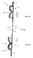
- the material 1 extends to a region 1A from which it can be deformed inwardly as in the inter-engagement form shown in Figures 1a and 1b .
- the assembly of member 15 about the snap band 14 has been captured onto the material 1 by the fold back 1A which is then attached by adhesively and/or stitching at 16.
- Members 14 and 15 need not be adhered one to the other but can be if desired.
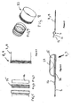
- FIG. 10 A preferred method if inter-engaging is as shown in Figure 10 .
- a ring 10 having an end region 6 or 7 of a flexible ring fitted there into reliant upon the deformability and resilience of the snap ring or band 14.
- Upon release from the condition as shown in Figure 10 a firm inter-engagement as shown in Figures 1A and 1B will result.
- a suitable plastics material can be used for the band 15. It is shape retaining but can be resilient so that it can conform to the deformation required of the snap band 14 which preferably is of a suitable material e.g. a suitable steel (preferably stainless steel) or could be some appropriate composite or plastics material.
- the sleeve can be formed from a film material, from fibres (e.g. of a non-woven material or a woven material), or some combination of them both e.g. a hybrid.
- Fibre examples include polyester, nylon, KEVLARTM, PTFE, polyurethane, TEFLONTM, aramid, PP, etc.
- hybrids of a woven or non-woven material can be used in conjunction with film.
- a woven or non-woven material i.e. formed from fibres
- One such example is a KEVLARTM woven fabric and a polyurethane film.
- the inner surface of the flexible sleeve is to a food grade.
- the material of the flexible tube can be homogeneous, i.e. it can have localised regions of different properties (e.g. material, rigidity, etc) if that is desirable in a particular application.
- any suitable choice of material or materials or variation of the same material or same materials can be used as can any appropriate hybridisation of the structure for example a combination of KEVLARTM/SVEFLEX40 when cuffed by a cuff of the present invention provides much greater explosive resistance than a conventionally fitted SVEFLEXTM flexible coupler.
- some additional outside tethering arrangement can, if desired, be provided to ensure that any failure in use is unlikely to be catastrophic. Such external tethering however is not preferred.
- profiled end forms are within the scope of the invention that provide for appropriate retention. These may include one or more annular rib. They may include one or more channel. It is preferred that the profiling be of an annular nature rather than helical or otherwise.
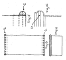
- FIGS 13 through 16 as described show a single annular rib 16 at each end of a flexible connector adapted to be received by a complementary profile.
- Each rib is analogously made to the twin rib form already described.
- Figures 17 through 20 show in a similar style to Figures 13 to 16 a double annular rib series of drawings.
- annular connector is single ribbed at one end or double ribbed, or as a hybrid of both, persons skilled in the art will appreciate how the system works.
- Figures 21 and 22 show a variation of the spigot of Figures 18 and 20 to the extent that there is provided an outwardly extended flange 18 at the bottom adapted itself to be welded to an appropriate surface about an opening or to be captured by an appropriate capture device.
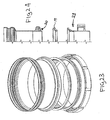
- Figure 23 shows a variation on such a theme, i.e. with a structure adapted to seal with a seal 19 into a bottom end of a connector at 20, the connector of Figures 23 and 24 being adapted to sit down on the appropriate annular seal 19 itself seating to a member 21.
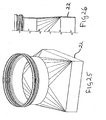
- Figures 25 and 26 show how a complementary member such as shown in Figure 20 can instead of maintaining the same general tubular form can evolve into other geometric forms. In the case of Figures 25 and 26 it evolves into a square tubular form 22 adapted for attachment to a square port or conduit.
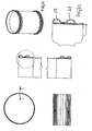
- Figures 27 through 30 shows a most preferred form of the spigot or ferrule. It can be of a metal (steel or SS) plastic or a combination of materials. This form has an inturned region 23 thus meaning that the inwardly directed ridge 24 separates two complete annular retention grooves 25 and 26 able to accommodate respectively parts 27 and 28 respectively of a flexible connector end as shown in Figures 31 , 31A and 32 .
- This shaping of the distal part to match the connector does two things - ensures a seal on two lips (27 and 28) and ensures less gap with the connector exteriorly to collect dust and dirt.
- An over sleeve for example of explosion suppressing Kevlar, can be provided to slip over the flexible connector and, if desired, extend over the spigot at each end. If desired it can be clamped for example by any clamping method onto the surface 29 or it can be left free but with sufficient lapping to ensure adequate explosion protection.
- Figure 31A shows the flexibility of the connector but even though it is connected, attention should be paid to Figures 36A through 36C .
- the distance AL between the spigots relates to a connector length CL as follows:
Landscapes
- Engineering & Computer Science (AREA)
- General Engineering & Computer Science (AREA)
- Mechanical Engineering (AREA)
- Quick-Acting Or Multi-Walled Pipe Joints (AREA)
- Rigid Pipes And Flexible Pipes (AREA)
- Air Transport Of Granular Materials (AREA)
- Joints Allowing Movement (AREA)
- Flanged Joints, Insulating Joints, And Other Joints (AREA)
- Infusion, Injection, And Reservoir Apparatuses (AREA)
Priority Applications (2)
| Application Number | Priority Date | Filing Date | Title |
|---|---|---|---|
| PL07793940T PL2021674T3 (pl) | 2006-05-12 | 2007-05-02 | Układ łączący z mankietem do przewodów i elementów rurowych |
| EP14174929.1A EP2811213A1 (en) | 2006-05-12 | 2007-05-02 | Cuffed connection system |
Applications Claiming Priority (4)
| Application Number | Priority Date | Filing Date | Title |
|---|---|---|---|
| NZ547189A NZ547189A (en) | 2006-05-12 | 2006-05-12 | Adjacent tubes with inner tube end band or cuff resiliently deformed inwardly to achieve assembly |
| NZ54817406 | 2006-06-27 | ||
| NZ55087006 | 2006-10-26 | ||
| PCT/NZ2007/000096 WO2007133094A1 (en) | 2006-05-12 | 2007-05-02 | Cuffed connection system for ducts and tubular members |
Related Child Applications (1)
| Application Number | Title | Priority Date | Filing Date |
|---|---|---|---|
| EP14174929.1A Division EP2811213A1 (en) | 2006-05-12 | 2007-05-02 | Cuffed connection system |
Publications (3)
| Publication Number | Publication Date |
|---|---|
| EP2021674A1 EP2021674A1 (en) | 2009-02-11 |
| EP2021674A4 EP2021674A4 (en) | 2011-10-19 |
| EP2021674B1 true EP2021674B1 (en) | 2014-07-02 |
Family
ID=38694117
Family Applications (2)
| Application Number | Title | Priority Date | Filing Date |
|---|---|---|---|
| EP07793940.3A Active EP2021674B1 (en) | 2006-05-12 | 2007-05-02 | Cuffed connection system for ducts and tubular members |
| EP14174929.1A Withdrawn EP2811213A1 (en) | 2006-05-12 | 2007-05-02 | Cuffed connection system |
Family Applications After (1)
| Application Number | Title | Priority Date | Filing Date |
|---|---|---|---|
| EP14174929.1A Withdrawn EP2811213A1 (en) | 2006-05-12 | 2007-05-02 | Cuffed connection system |
Country Status (13)
| Country | Link |
|---|---|
| US (2) | US7959190B2 (da) |
| EP (2) | EP2021674B1 (da) |
| JP (2) | JP5378991B2 (da) |
| CN (3) | CN102635744B (da) |
| AU (1) | AU2007250635B2 (da) |
| CA (1) | CA2650144C (da) |
| DK (1) | DK2021674T3 (da) |
| ES (1) | ES2510541T3 (da) |
| MX (1) | MX2008014430A (da) |
| MY (1) | MY167767A (da) |
| PL (1) | PL2021674T3 (da) |
| PT (1) | PT2021674E (da) |
| WO (1) | WO2007133094A1 (da) |
Families Citing this family (28)
| Publication number | Priority date | Publication date | Assignee | Title |
|---|---|---|---|---|
| CA118257S (en) * | 2006-05-15 | 2008-01-02 | Filtercorp Internat Ltd | Tube for receiving a flexible connector at its profiled end |
| CA118256S (en) * | 2006-05-15 | 2008-01-02 | Filtercorp Internat Ltd | Flexible tubular connector with self supporting end bands |
| FR2946119B1 (fr) * | 2009-06-02 | 2015-03-20 | Areva Nc | Dispositif de connexion pour systeme de remplissage de jarres pour la fabrication de combustible nucleaire. |
| DE102010009179A1 (de) * | 2010-02-24 | 2011-08-25 | Andocksysteme G. Untch GmbH, 79410 | Verbindungsvorrichtung zum Verbinden eines flexiblen Gebindes mit einem Flansch oder einem Anschlussring |
| US20130042414A1 (en) * | 2011-08-17 | 2013-02-21 | Stryker Corporation | Air inlet for patient support device |
| KR101949188B1 (ko) * | 2012-01-12 | 2019-02-18 | 삼성전자주식회사 | 드럼 세탁기 |
| US10591179B2 (en) * | 2012-08-14 | 2020-03-17 | Ductmate Industries, Inc. | Flexible register boot for heated and cooled air |
| WO2014207705A1 (en) * | 2013-06-27 | 2014-12-31 | Filtercorp International Limited | Improvements in or for filtration systems |
| FR3011903B1 (fr) * | 2013-10-14 | 2016-01-01 | Techlam Sas | Joint flexible pour conduites d'hydrocarbure, procede de detection de fuite dans un tel joint, et systeme de detection de fuite d'hydrocarbure dans un tel joint. |
| JP6313582B2 (ja) * | 2013-12-04 | 2018-04-18 | アイシン産業株式会社 | ジョイント構造 |
| CN105864542B (zh) * | 2015-01-22 | 2018-06-08 | 李苗 | 柔性密封消防连接装置及其使用方法 |
| WO2017059476A1 (en) * | 2015-10-06 | 2017-04-13 | Rkc Holdings Pty Ltd | Airbag protection sleeve |
| US20170225848A1 (en) * | 2016-02-04 | 2017-08-10 | Heath Hill | Bottle Cap Restrictor |
| US10514119B2 (en) * | 2016-11-22 | 2019-12-24 | Schauenburg Flexadux Corporation | Duct coupling system |
| KR20200019866A (ko) * | 2017-06-19 | 2020-02-25 | 듀폰 폴리머스, 인크. | 유체 도관 |
| CN107606333A (zh) * | 2017-10-20 | 2018-01-19 | 安徽安塑管业有限公司 | 一种聚乙烯塑钢缠绕管 |
| CN108253211B (zh) * | 2018-01-25 | 2019-11-08 | 胜利油田金岛实业有限责任公司胜岛石油机械厂 | 一种高分子内衬加长接箍 |
| US11131477B2 (en) * | 2018-03-15 | 2021-09-28 | Nationwide Tarps, Inc. | Connector for flexible duct, flexible duct with interchangeable end, and method thereof |
| DE102018208477A1 (de) | 2018-05-29 | 2019-12-05 | Eagleburgmann Germany Gmbh & Co. Kg | Kompensatoranordnung für Transportsysteme |
| FR3091571B1 (fr) * | 2019-01-04 | 2022-07-29 | Weh & Co | Procédé d’insertion de raccord, raccord et exosquelette, pour gaine dans un système de ventilation |
| WO2020141488A1 (fr) * | 2019-01-04 | 2020-07-09 | Weh & Co | Procédé d'insertion de raccord, raccord et exosquelette, pour gaine dans un système de ventilation |
| GB201903367D0 (en) * | 2019-03-12 | 2019-04-24 | Bio Optimal Ltd | Connection System |
| AU2020284165B2 (en) | 2019-05-31 | 2026-03-12 | BFM Technology Limited | A bag loading nozzle |
| CA3085075A1 (en) | 2020-06-30 | 2021-12-30 | F.X. Construction Inc. | Fitting for a rain gutter downpipe |
| CA3221871A1 (en) * | 2021-06-18 | 2022-12-22 | Anais Eymery | Flexible trunk and rigid support arrangement for the transfer of sterile components from a container |
| DE102021115891A1 (de) | 2021-06-18 | 2022-12-22 | Fr. Jacob Söhne Gmbh & Co. Kg | Rohrförmige Förderleitung |
| WO2024023773A1 (en) * | 2022-07-29 | 2024-02-01 | BFM Technology Limited | Rotary airlock bulk inlet connector |
| WO2024023772A1 (en) * | 2022-07-29 | 2024-02-01 | BFM Technology Limited | Vibration decoupling connector |
Family Cites Families (60)
| Publication number | Priority date | Publication date | Assignee | Title |
|---|---|---|---|---|
| US282968A (en) | 1883-08-14 | Hitching device | ||
| US1083002A (en) * | 1913-08-14 | 1913-12-30 | American Rolling Mill Co | Sheet-metal culvert. |
| US1099833A (en) | 1913-12-20 | 1914-06-09 | Wolf Company | Sifter and bolter. |
| US1525538A (en) * | 1924-08-09 | 1925-02-10 | Evans William Hooper | Fabric-hose coupling |
| US1948909A (en) * | 1931-08-21 | 1934-02-27 | Evans William Hooper | Flexible ventilating tubing or the like |
| US2003732A (en) * | 1935-01-30 | 1935-06-04 | Frank M Bins | Coupling for canvas tubing |
| US2366067A (en) * | 1943-06-04 | 1944-12-26 | Smith Franklin Elijah | Hose coupling |
| US2386562A (en) * | 1944-05-22 | 1945-10-09 | Frank D Mahoney | Hose coupling |
| US2567773A (en) * | 1947-12-18 | 1951-09-11 | Goodrich Co B F | Hose coupling |
| GB739575A (en) * | 1953-09-03 | 1955-11-02 | Us Rubber Co | Improvements in hose and coupling combination |
| US2736521A (en) * | 1954-04-13 | 1956-02-28 | Boeing Co | Flexible tank wall edge seals |
| US2816782A (en) * | 1955-04-26 | 1957-12-17 | Robinson Clay Product Company | Resilient toroidal push-type pipe joint |
| US3099015A (en) * | 1960-06-14 | 1963-07-30 | William J Renehan | Joint for interconnecting tubular members |
| US3114567A (en) * | 1960-08-09 | 1963-12-17 | Goodrich Co B F | Fluid-tight connector |
| US3413021A (en) * | 1965-10-20 | 1968-11-26 | Ferry Cap & Set Screw Co | Tubular coupling |
| US3376055A (en) * | 1966-04-19 | 1968-04-02 | Garlock Inc | Coupling for beadless-end pipes |
| US3512805A (en) * | 1968-08-16 | 1970-05-19 | Charles B Glatz | Means for joining two conduits |
| US3717305A (en) | 1970-12-10 | 1973-02-20 | H Hedges | Fuel injection nozzle assembly |
| US3820826A (en) * | 1972-01-19 | 1974-06-28 | Dickey Clay Mfg Co W | Fitting structure for pipe |
| US3938834A (en) * | 1973-04-20 | 1976-02-17 | Wavin B.V. | Pipe connection for plastic pipes comprising a transversely or helically corrugated pipe-connecting part |
| US3873137A (en) * | 1973-09-19 | 1975-03-25 | Seiichi Yamaguchi | Bellows-type joint assembly |
| US3945617A (en) * | 1974-01-14 | 1976-03-23 | Callery Thomas R | Mixing method and means |
| AU8476675A (en) * | 1974-09-12 | 1977-03-17 | Perenzin B | Pipe connector |
| SE382675B (sv) | 1974-12-12 | 1976-02-09 | Lindab Lindhs Industri Ab | Rorformigt skarvstycke. |
| US4015961A (en) * | 1976-01-08 | 1977-04-05 | Air Filters, Inc. | Filter bag and coupling |
| PL205239A1 (da) | 1978-03-09 | 1979-11-05 | Biprohut | |
| US4405159A (en) * | 1981-06-16 | 1983-09-20 | Wastemate Corporation | Waste disposer coupling |
| ATE11952T1 (de) * | 1982-10-11 | 1985-03-15 | Rost Peter | Loesbare klemmverbindung. |
| DE3409954A1 (de) * | 1984-03-17 | 1985-09-26 | Miele & Cie GmbH & Co, 4830 Gütersloh | Ablaufschlauch fuer wasch- und geschirrspuelmaschinen |
| US4625998A (en) * | 1984-04-02 | 1986-12-02 | Draudt Donald A | Swivel hose couplings |
| US4714279A (en) * | 1986-11-03 | 1987-12-22 | Lincoln Custeau | Exhaust pipe coupler |
| US4768563A (en) * | 1987-10-29 | 1988-09-06 | Flexfab, Inc. | Quick-disconnect hose |
| CN2046969U (zh) * | 1988-12-17 | 1989-11-01 | 李天宝 | 快速接头 |
| FR2657941B1 (fr) * | 1990-02-07 | 1992-04-17 | Caoutchouc Manuf Plastique | Armature de renfort articulee pour talon de renforcement de structure tubulaire souple et structure tubulaire souple comportant une telle armature de renfort. |
| GB2245944B (en) * | 1990-07-09 | 1993-12-15 | Thermopol Limited | Hose and hollow member arrangements |
| CA2032830C (en) * | 1990-12-20 | 1994-07-26 | R.S.T. Instruments Ltd. | Coupling |
| FR2676680A1 (fr) | 1991-04-22 | 1992-11-27 | Dhinaun Jean | Tuyau polyvalent pour l'assainissement et la vidange. |
| US5190322A (en) * | 1991-09-06 | 1993-03-02 | Chrysler Corp | Sealing cuff for blow molded plastic components |
| DE4239909C1 (de) * | 1992-11-27 | 1994-05-05 | Rasmussen Gmbh | Rohrartiger Stutzen |
| US5308123A (en) * | 1992-12-21 | 1994-05-03 | Ncr Corporation | Corrugated hose coupling |
| US5791696A (en) * | 1993-06-14 | 1998-08-11 | Tokai Rubber Industries, Ltd. | Hose with a protector |
| JPH08192915A (ja) * | 1995-01-14 | 1996-07-30 | Aramu Kk | 粉粒状物移送筒の連結装置 |
| US5813701A (en) | 1996-03-07 | 1998-09-29 | Gutter World, Inc. | Repositionable flexible downspout extension |
| JPH11336974A (ja) | 1998-05-22 | 1999-12-07 | Hitachi Constr Mach Co Ltd | 建設機械の低圧配管接続構造 |
| DE69825637T2 (de) * | 1998-11-06 | 2005-08-11 | Lindab Ab | Dichtring für röhrenförmiges Element |
| JP2001104508A (ja) * | 1999-10-13 | 2001-04-17 | Nohmi Bosai Ltd | 消火設備の配管 |
| GB0019882D0 (en) * | 2000-08-11 | 2000-09-27 | Thermopol Limited | A hose and pipe coupling arrangement |
| JP3925775B2 (ja) * | 2001-09-07 | 2007-06-06 | 豊田合成株式会社 | 樹脂チューブ |
| US6908121B2 (en) | 2001-10-22 | 2005-06-21 | Weatherford/Lamb, Inc. | Locking arrangement for a threaded connector |
| US6692039B2 (en) * | 2002-02-08 | 2004-02-17 | Hunting Hti Rehab, Inc., Llc | Internal conduit sealing installation |
| US7125053B2 (en) | 2002-06-10 | 2006-10-24 | Weatherford/ Lamb, Inc. | Pre-expanded connector for expandable downhole tubulars |
| US6941972B2 (en) | 2002-07-25 | 2005-09-13 | Hancor, Inc. | Corrugated pipe |
| DE10261557B4 (de) * | 2002-12-23 | 2005-06-02 | Weinhold, Karl, Dipl.-Ing. | Kupplung für Stahlwendelschläuche |
| CN2765036Y (zh) * | 2003-09-08 | 2006-03-15 | 黄新东 | 本体螺旋不锈钢管接头 |
| SE526730C2 (sv) * | 2003-12-17 | 2005-11-01 | Volvo Lastvagnar Ab | Koppling för anslutning av en slang till en styv röranslutning |
| JP4809937B2 (ja) | 2004-10-15 | 2011-11-09 | ホシザキ電機株式会社 | フレキシブル管 |
| CN100394095C (zh) * | 2004-10-22 | 2008-06-11 | 东海橡胶工业株式会社 | 燃料箱的熔接接头 |
| PL205157B1 (pl) | 2005-04-26 | 2010-03-31 | Kominus Spo & Lstrok Ka Z Ogra | Złącze sprężystych rur cienkościennych |
| EP1988946B1 (en) * | 2006-03-02 | 2016-04-20 | Gambro Lundia AB | A hydraulic connector and a hydraulic circuit incorporating the connector |
| CN1888497A (zh) * | 2006-07-28 | 2007-01-03 | 玉环江林水暖管业有限公司 | 一种煤气防漏阀 |
-
2007
- 2007-05-02 WO PCT/NZ2007/000096 patent/WO2007133094A1/en not_active Ceased
- 2007-05-02 AU AU2007250635A patent/AU2007250635B2/en active Active
- 2007-05-02 CA CA2650144A patent/CA2650144C/en active Active
- 2007-05-02 DK DK07793940.3T patent/DK2021674T3/da active
- 2007-05-02 US US11/922,143 patent/US7959190B2/en active Active
- 2007-05-02 PT PT77939403T patent/PT2021674E/pt unknown
- 2007-05-02 CN CN201210114974.3A patent/CN102635744B/zh active Active
- 2007-05-02 ES ES07793940.3T patent/ES2510541T3/es active Active
- 2007-05-02 EP EP07793940.3A patent/EP2021674B1/en active Active
- 2007-05-02 PL PL07793940T patent/PL2021674T3/pl unknown
- 2007-05-02 JP JP2009510909A patent/JP5378991B2/ja active Active
- 2007-05-02 MX MX2008014430A patent/MX2008014430A/es active IP Right Grant
- 2007-05-02 MY MYPI20084384A patent/MY167767A/en unknown
- 2007-05-02 CN CN200780017231.1A patent/CN101583819B/zh active Active
- 2007-05-02 CN CN201210115194.0A patent/CN102635745B/zh active Active
- 2007-05-02 EP EP14174929.1A patent/EP2811213A1/en not_active Withdrawn
-
2011
- 2011-04-25 US US13/093,334 patent/US8590943B2/en active Active
-
2013
- 2013-07-12 JP JP2013147103A patent/JP2013224744A/ja active Pending
Also Published As
| Publication number | Publication date |
|---|---|
| EP2021674A1 (en) | 2009-02-11 |
| US7959190B2 (en) | 2011-06-14 |
| CN102635744A (zh) | 2012-08-15 |
| US20080265570A1 (en) | 2008-10-30 |
| ES2510541T3 (es) | 2014-10-21 |
| CN102635745B (zh) | 2016-01-13 |
| CA2650144C (en) | 2016-11-22 |
| DK2021674T3 (da) | 2014-10-06 |
| PT2021674E (pt) | 2014-10-06 |
| PL2021674T3 (pl) | 2014-12-31 |
| EP2021674A4 (en) | 2011-10-19 |
| MY167767A (en) | 2018-09-24 |
| JP2009537002A (ja) | 2009-10-22 |
| CN102635744B (zh) | 2016-01-06 |
| AU2007250635A1 (en) | 2007-11-22 |
| WO2007133094A1 (en) | 2007-11-22 |
| CN101583819B (zh) | 2014-04-09 |
| CN102635745A (zh) | 2012-08-15 |
| AU2007250635B2 (en) | 2012-09-13 |
| JP5378991B2 (ja) | 2013-12-25 |
| JP2013224744A (ja) | 2013-10-31 |
| MX2008014430A (es) | 2009-03-09 |
| HK1126849A1 (en) | 2009-09-11 |
| US8590943B2 (en) | 2013-11-26 |
| CN101583819A (zh) | 2009-11-18 |
| CA2650144A1 (en) | 2007-11-22 |
| EP2811213A1 (en) | 2014-12-10 |
| US20110260448A1 (en) | 2011-10-27 |
Similar Documents
| Publication | Publication Date | Title |
|---|---|---|
| EP2021674B1 (en) | Cuffed connection system for ducts and tubular members | |
| US5366260A (en) | Plastic pipe coupler | |
| AU690142B2 (en) | Joint and seal system for air transfer tubes | |
| US20050134037A1 (en) | Elastic coupling for universal vacuum extension kit | |
| EP0135531B1 (en) | Seal, especially for a coupling between an air intake on a tilting truck cab and a pipe securely mounted on the chassis | |
| US9976677B2 (en) | Dual use coupling end for pipes and fittings | |
| WO1998034058A2 (en) | Composite plastic sanitary fitting | |
| AU2012216524B2 (en) | Cuffed connection system for ducts and tubular members | |
| EP3917838B1 (en) | A bag loading nozzle | |
| HK1126849B (en) | Cuffed connection system for ducts and tubular members | |
| NZ547189A (en) | Adjacent tubes with inner tube end band or cuff resiliently deformed inwardly to achieve assembly | |
| US20100270796A1 (en) | Kink eliminator connector | |
| US20040262922A1 (en) | Assembly system for a pipe coupling | |
| NZ562896A (en) | Method of connecting flexible tubing by resilient deformation of tube ends, with other than flanked rib connection | |
| CA2526560C (en) | Rotatable coupling | |
| SE466566B (sv) | Anordning foer anslutning av en tunnvaeggig slang till ett roerformigt element | |
| WO2022214555A1 (en) | A sleeve for a coupling | |
| WO2005001323A1 (en) | Assembly system for a pipe coupling | |
| JP3696777B2 (ja) | 離脱防止金具 | |
| CN121941874A (zh) | 振动解耦连接器 | |
| CN113451958A (zh) | 一种冷缩型防水器件 | |
| JPH04119686U (ja) | 仮設用給水管構造 |
Legal Events
| Date | Code | Title | Description |
|---|---|---|---|
| PUAI | Public reference made under article 153(3) epc to a published international application that has entered the european phase |
Free format text: ORIGINAL CODE: 0009012 |
|
| 17P | Request for examination filed |
Effective date: 20080218 |
|
| AK | Designated contracting states |
Kind code of ref document: A1 Designated state(s): AT BE BG CH CY CZ DE DK EE ES FI FR GB GR HU IE IS IT LI LT LU LV MC MT NL PL PT RO SE SI SK TR |
|
| AX | Request for extension of the european patent |
Extension state: AL BA HR MK RS |
|
| REG | Reference to a national code |
Ref country code: HK Ref legal event code: DE Ref document number: 1126849 Country of ref document: HK |
|
| RAP1 | Party data changed (applicant data changed or rights of an application transferred) |
Owner name: BFM TECHNOLOGY LIMITED |
|
| A4 | Supplementary search report drawn up and despatched |
Effective date: 20110915 |
|
| RIC1 | Information provided on ipc code assigned before grant |
Ipc: F16L 25/10 20060101ALI20110909BHEP Ipc: B65G 53/52 20060101ALI20110909BHEP Ipc: F16L 33/32 20060101ALI20110909BHEP Ipc: F16L 33/28 20060101ALI20110909BHEP Ipc: F16L 27/103 20060101ALI20110909BHEP Ipc: F16L 27/108 20060101ALI20110909BHEP Ipc: B65G 53/00 20060101ALI20110909BHEP Ipc: F16L 37/091 20060101ALI20110909BHEP Ipc: F16L 27/107 20060101ALI20110909BHEP Ipc: F16L 37/02 20060101AFI20110909BHEP |
|
| 17Q | First examination report despatched |
Effective date: 20120605 |
|
| GRAP | Despatch of communication of intention to grant a patent |
Free format text: ORIGINAL CODE: EPIDOSNIGR1 |
|
| INTG | Intention to grant announced |
Effective date: 20140121 |
|
| GRAS | Grant fee paid |
Free format text: ORIGINAL CODE: EPIDOSNIGR3 |
|
| GRAA | (expected) grant |
Free format text: ORIGINAL CODE: 0009210 |
|
| AK | Designated contracting states |
Kind code of ref document: B1 Designated state(s): AT BE BG CH CY CZ DE DK EE ES FI FR GB GR HU IE IS IT LI LT LU LV MC MT NL PL PT RO SE SI SK TR |
|
| AX | Request for extension of the european patent |
Extension state: AL BA HR MK RS |
|
| REG | Reference to a national code |
Ref country code: GB Ref legal event code: FG4D |
|
| REG | Reference to a national code |
Ref country code: AT Ref legal event code: REF Ref document number: 676124 Country of ref document: AT Kind code of ref document: T Effective date: 20140715 Ref country code: CH Ref legal event code: EP |
|
| REG | Reference to a national code |
Ref country code: IE Ref legal event code: FG4D |
|
| REG | Reference to a national code |
Ref country code: DE Ref legal event code: R096 Ref document number: 602007037483 Country of ref document: DE Effective date: 20140814 |
|
| REG | Reference to a national code |
Ref country code: RO Ref legal event code: EPE |
|
| REG | Reference to a national code |
Ref country code: DK Ref legal event code: T3 Effective date: 20141002 Ref country code: PT Ref legal event code: SC4A Free format text: AVAILABILITY OF NATIONAL TRANSLATION Effective date: 20140929 |
|
| REG | Reference to a national code |
Ref country code: CH Ref legal event code: NV Representative=s name: RENTSCH PARTNER AG, CH |
|
| REG | Reference to a national code |
Ref country code: SE Ref legal event code: TRGR Ref country code: ES Ref legal event code: FG2A Ref document number: 2510541 Country of ref document: ES Kind code of ref document: T3 Effective date: 20141021 |
|
| REG | Reference to a national code |
Ref country code: NL Ref legal event code: T3 |
|
| REG | Reference to a national code |
Ref country code: LT Ref legal event code: MG4D |
|
| REG | Reference to a national code |
Ref country code: PL Ref legal event code: T3 |
|
| REG | Reference to a national code |
Ref country code: GR Ref legal event code: EP Ref document number: 20140402026 Country of ref document: GR Effective date: 20141121 |
|
| PG25 | Lapsed in a contracting state [announced via postgrant information from national office to epo] |
Ref country code: LT Free format text: LAPSE BECAUSE OF FAILURE TO SUBMIT A TRANSLATION OF THE DESCRIPTION OR TO PAY THE FEE WITHIN THE PRESCRIBED TIME-LIMIT Effective date: 20140702 |
|
| PG25 | Lapsed in a contracting state [announced via postgrant information from national office to epo] |
Ref country code: CY Free format text: LAPSE BECAUSE OF FAILURE TO SUBMIT A TRANSLATION OF THE DESCRIPTION OR TO PAY THE FEE WITHIN THE PRESCRIBED TIME-LIMIT Effective date: 20140702 Ref country code: LV Free format text: LAPSE BECAUSE OF FAILURE TO SUBMIT A TRANSLATION OF THE DESCRIPTION OR TO PAY THE FEE WITHIN THE PRESCRIBED TIME-LIMIT Effective date: 20140702 |
|
| REG | Reference to a national code |
Ref country code: HU Ref legal event code: AG4A Ref document number: E021835 Country of ref document: HU |
|
| REG | Reference to a national code |
Ref country code: DE Ref legal event code: R097 Ref document number: 602007037483 Country of ref document: DE |
|
| PG25 | Lapsed in a contracting state [announced via postgrant information from national office to epo] |
Ref country code: EE Free format text: LAPSE BECAUSE OF FAILURE TO SUBMIT A TRANSLATION OF THE DESCRIPTION OR TO PAY THE FEE WITHIN THE PRESCRIBED TIME-LIMIT Effective date: 20140702 Ref country code: SK Free format text: LAPSE BECAUSE OF FAILURE TO SUBMIT A TRANSLATION OF THE DESCRIPTION OR TO PAY THE FEE WITHIN THE PRESCRIBED TIME-LIMIT Effective date: 20140702 |
|
| PLBE | No opposition filed within time limit |
Free format text: ORIGINAL CODE: 0009261 |
|
| STAA | Information on the status of an ep patent application or granted ep patent |
Free format text: STATUS: NO OPPOSITION FILED WITHIN TIME LIMIT |
|
| 26N | No opposition filed |
Effective date: 20150407 |
|
| REG | Reference to a national code |
Ref country code: HK Ref legal event code: GR Ref document number: 1126849 Country of ref document: HK |
|
| PG25 | Lapsed in a contracting state [announced via postgrant information from national office to epo] |
Ref country code: SI Free format text: LAPSE BECAUSE OF FAILURE TO SUBMIT A TRANSLATION OF THE DESCRIPTION OR TO PAY THE FEE WITHIN THE PRESCRIBED TIME-LIMIT Effective date: 20140702 |
|
| PG25 | Lapsed in a contracting state [announced via postgrant information from national office to epo] |
Ref country code: MC Free format text: LAPSE BECAUSE OF FAILURE TO SUBMIT A TRANSLATION OF THE DESCRIPTION OR TO PAY THE FEE WITHIN THE PRESCRIBED TIME-LIMIT Effective date: 20140702 |
|
| REG | Reference to a national code |
Ref country code: FR Ref legal event code: PLFP Year of fee payment: 10 |
|
| PG25 | Lapsed in a contracting state [announced via postgrant information from national office to epo] |
Ref country code: MT Free format text: LAPSE BECAUSE OF FAILURE TO SUBMIT A TRANSLATION OF THE DESCRIPTION OR TO PAY THE FEE WITHIN THE PRESCRIBED TIME-LIMIT Effective date: 20140702 |
|
| REG | Reference to a national code |
Ref country code: FR Ref legal event code: PLFP Year of fee payment: 11 |
|
| REG | Reference to a national code |
Ref country code: CH Ref legal event code: PCAR Free format text: NEW ADDRESS: BELLERIVESTRASSE 203 POSTFACH, 8034 ZUERICH (CH) |
|
| REG | Reference to a national code |
Ref country code: FR Ref legal event code: PLFP Year of fee payment: 12 |
|
| P01 | Opt-out of the competence of the unified patent court (upc) registered |
Effective date: 20230530 |
|
| PGFP | Annual fee paid to national office [announced via postgrant information from national office to epo] |
Ref country code: NL Payment date: 20250521 Year of fee payment: 19 |
|
| PGFP | Annual fee paid to national office [announced via postgrant information from national office to epo] |
Ref country code: FI Payment date: 20250522 Year of fee payment: 19 |
|
| PGFP | Annual fee paid to national office [announced via postgrant information from national office to epo] |
Ref country code: PL Payment date: 20250429 Year of fee payment: 19 Ref country code: DE Payment date: 20250528 Year of fee payment: 19 |
|
| PGFP | Annual fee paid to national office [announced via postgrant information from national office to epo] |
Ref country code: ES Payment date: 20250603 Year of fee payment: 19 Ref country code: GB Payment date: 20250518 Year of fee payment: 19 Ref country code: DK Payment date: 20250530 Year of fee payment: 19 |
|
| PGFP | Annual fee paid to national office [announced via postgrant information from national office to epo] |
Ref country code: IS Payment date: 20250519 Year of fee payment: 19 Ref country code: HU Payment date: 20250430 Year of fee payment: 19 |
|
| PGFP | Annual fee paid to national office [announced via postgrant information from national office to epo] |
Ref country code: LU Payment date: 20250527 Year of fee payment: 19 Ref country code: BE Payment date: 20250523 Year of fee payment: 19 Ref country code: IT Payment date: 20250521 Year of fee payment: 19 |
|
| PGFP | Annual fee paid to national office [announced via postgrant information from national office to epo] |
Ref country code: PT Payment date: 20250422 Year of fee payment: 19 |
|
| PGFP | Annual fee paid to national office [announced via postgrant information from national office to epo] |
Ref country code: FR Payment date: 20250519 Year of fee payment: 19 |
|
| PGFP | Annual fee paid to national office [announced via postgrant information from national office to epo] |
Ref country code: BG Payment date: 20250519 Year of fee payment: 19 Ref country code: GR Payment date: 20250520 Year of fee payment: 19 |
|
| PGFP | Annual fee paid to national office [announced via postgrant information from national office to epo] |
Ref country code: CH Payment date: 20250601 Year of fee payment: 19 |
|
| PGFP | Annual fee paid to national office [announced via postgrant information from national office to epo] |
Ref country code: AT Payment date: 20250526 Year of fee payment: 19 Ref country code: RO Payment date: 20250430 Year of fee payment: 19 |
|
| PGFP | Annual fee paid to national office [announced via postgrant information from national office to epo] |
Ref country code: TR Payment date: 20250429 Year of fee payment: 19 |
|
| PGFP | Annual fee paid to national office [announced via postgrant information from national office to epo] |
Ref country code: CZ Payment date: 20250422 Year of fee payment: 19 |
|
| PGFP | Annual fee paid to national office [announced via postgrant information from national office to epo] |
Ref country code: IE Payment date: 20250519 Year of fee payment: 19 |
|
| PGFP | Annual fee paid to national office [announced via postgrant information from national office to epo] |
Ref country code: SE Payment date: 20250520 Year of fee payment: 19 |