EP2020734A1 - Schutzabdeckung zum Befestigen durch Einschnappen auf einem Flansch einer elektrischen umlaufenden Maschine und elektrische umlaufende Maschine, die eine solche Abdeckung umfasst - Google Patents
Schutzabdeckung zum Befestigen durch Einschnappen auf einem Flansch einer elektrischen umlaufenden Maschine und elektrische umlaufende Maschine, die eine solche Abdeckung umfasst Download PDFInfo
- Publication number
- EP2020734A1 EP2020734A1 EP08159656A EP08159656A EP2020734A1 EP 2020734 A1 EP2020734 A1 EP 2020734A1 EP 08159656 A EP08159656 A EP 08159656A EP 08159656 A EP08159656 A EP 08159656A EP 2020734 A1 EP2020734 A1 EP 2020734A1
- Authority
- EP
- European Patent Office
- Prior art keywords
- chimney
- flange
- hood
- tongue
- cover
- Prior art date
- Legal status (The legal status is an assumption and is not a legal conclusion. Google has not performed a legal analysis and makes no representation as to the accuracy of the status listed.)
- Granted
Links
- 230000001681 protective effect Effects 0.000 title claims description 6
- 210000002105 tongue Anatomy 0.000 claims description 62
- 239000007858 starting material Substances 0.000 claims description 17
- 238000000465 moulding Methods 0.000 description 6
- 239000000463 material Substances 0.000 description 3
- 230000036961 partial effect Effects 0.000 description 3
- 238000009423 ventilation Methods 0.000 description 3
- 238000001816 cooling Methods 0.000 description 2
- 230000033001 locomotion Effects 0.000 description 2
- 229910052751 metal Inorganic materials 0.000 description 2
- 239000002184 metal Substances 0.000 description 2
- 230000002829 reductive effect Effects 0.000 description 2
- 230000002441 reversible effect Effects 0.000 description 2
- 229910001369 Brass Inorganic materials 0.000 description 1
- 229910052782 aluminium Inorganic materials 0.000 description 1
- XAGFODPZIPBFFR-UHFFFAOYSA-N aluminium Chemical group [Al] XAGFODPZIPBFFR-UHFFFAOYSA-N 0.000 description 1
- 239000011324 bead Substances 0.000 description 1
- 230000005540 biological transmission Effects 0.000 description 1
- 239000010951 brass Substances 0.000 description 1
- 210000000078 claw Anatomy 0.000 description 1
- 230000000295 complement effect Effects 0.000 description 1
- 230000009977 dual effect Effects 0.000 description 1
- 210000005069 ears Anatomy 0.000 description 1
- 239000012530 fluid Substances 0.000 description 1
- 238000012423 maintenance Methods 0.000 description 1
- 230000000284 resting effect Effects 0.000 description 1
Images


Classifications
-
- H—ELECTRICITY
- H02—GENERATION; CONVERSION OR DISTRIBUTION OF ELECTRIC POWER
- H02K—DYNAMO-ELECTRIC MACHINES
- H02K5/00—Casings; Enclosures; Supports
- H02K5/04—Casings or enclosures characterised by the shape, form or construction thereof
- H02K5/10—Casings or enclosures characterised by the shape, form or construction thereof with arrangements for protection from ingress, e.g. water or fingers
-
- H—ELECTRICITY
- H02—GENERATION; CONVERSION OR DISTRIBUTION OF ELECTRIC POWER
- H02K—DYNAMO-ELECTRIC MACHINES
- H02K5/00—Casings; Enclosures; Supports
- H02K5/04—Casings or enclosures characterised by the shape, form or construction thereof
- H02K5/22—Auxiliary parts of casings not covered by groups H02K5/06-H02K5/20, e.g. shaped to form connection boxes or terminal boxes
- H02K5/225—Terminal boxes or connection arrangements
Definitions
- the present invention relates to a protective cover intended to be fixed by snapping on a flange of a rotating electrical machine and a rotating electrical machine comprising such a cover.
- Such a hood and such a rotating electrical machine are described for example in the document WO 01/69762 .
- the machine is a reversible alternator for a motor vehicle with a heat engine.
- This reversible alternator is called alternator-starter.
- This alternator-starter transforms mechanical energy into electrical energy when it works in current generator mode, in particular to recharge the battery and / or to supply the consumers of the on-board vehicle network.
- This alternator-starter transforms electrical energy into mechanical energy when working in electric motor mode to start the engine of the vehicle.
- please refer to this document WO 01/69762 please refer to this document WO 01/69762 .
- bearings carry centrally a bearing means, such as a ball bearing for rotary mounting of the alternator-starter shaft.
- This shaft passes through the bearings to carry the slip rings at its rear end of smaller diameter and at its front end a drive member, such as a pulley, belonging to a transmission of motion occurring between the crankshaft of the engine and the engine. 'alternator-starter shaft.
- the cover surrounds the brush holder and also a current rectifier bridge as well as a voltage regulator integral with the brush holder as described for example in FIG. document US 7,019,424 .
- the cover has an opening for the passage of a connector connected to the voltage regulator and another opening for the passage of a terminal, called B + terminal, to be connected via a cable to the positive terminal of the battery .
- This terminal is integral with the positive radiator that includes the current rectifier bridge.
- the hood is hollow in shape and is perforated for passage of a cooling air flow respectively of the alternator-starter and the alternator.
- This circulation of cooling air is generated by the rotation of at least one rear fan integral with the rotor of the alternator-starter or the alternator.
- the cover is integral with the flange formed by the rear bearing of the alternator or the alternator-starter.
- the cover is fixed via deformable snap-fastening tongues secured to the bottom of the cover, by snapping on members threaded, such as studs, secured to the rear bearing so that it has a bottom, generally transverse orientation relative to the axis of the alternator-starter shaft or the alternator, and a flange overall axial orientation with respect to this axis as visible for example in the figure 7 of the document WO 01/69762 and at the figure 8 of the document US 7,019,424 ; in which the studs have not been represented for simplicity
- This stud 20 comprises a first threaded portion 21 of diameter d1, a nut 22, a washer 23, a portion 24 with rings and a second threaded portion 25 of diameter d2 advantageously equal to the diameter d1.
- the parts 21 and 25, the nut 22 and the rings 24 are monobloc.
- the washer 23 is captive thanks to the retaining rings 24.
- the second threaded portion 25 is intended to be screwed into a threaded stud from the bottom of the rear bearing as visible in the figure 7 of the document US 6,798,094 and in figures 7 and 12 of the document WO 01/69762 . This screwing is performed by means of the nut 23 operated by a tool.
- the washer 23, here conical to stop without burr, is intended to bear for example on the ears of the sensor holder of the figure 9 of the document WO 01/69762 ; the second threaded portion 25 passing through the oblong hole of said ear.
- the nut 22, manipulated by the tool, makes it possible to clamp the relevant ear of the sensor holder between the stud of the rear bearing and the washer 23.
- the nut makes it possible to tighten the positive radiator and the document connector US 6,798,094 between the stud of the rear bearing, in which is screwed the portion 25, and the washer 23. To do this must provide an electrically insulating part, called an insulating bushing, to avoid short circuit.
- This barrel has an upper portion in the form of a first sleeve extended by a second sleeve of greater diameter passing through a hole of the positive radiator of the current rectifier bridge. It is constituted a washer in favor of the change of diameter between the two sleeves.
- the washer of the barrel is interposed between the washer 23 of the stud 20 and the edge of the hole of the positive radiator of the current rectifier bridge.
- the threaded portion 25 passes through the second sleeve of the barrel to screw into the threaded hole of the stud of the rear bearing.
- the rings 24 are intended to penetrate into the second sleeve of the insulating barrel, while the first sleeve serves to accommodate the nut and the washer 23.
- the first threaded portion 21 is intended to engage resiliently deformable tongues 33 belonging to a generally cylindrical assembly chimney 32 integral with the bottom 31 of the hood 30.
- This chimney 32 more precisely the wall of the chimney defining the here, extends here perpendicular to the bottom 31.
- the chimney 32 is obtained by molding with the cover, for example plastic.
- This chimney 32 has a wall The axis of the chimney 32 coincides with the axis A of the stud 20.
- the tongues 33 extend inside the chimney 32 and perpendicular to the axis A.
- This chimney 32 penetrates locally inside the hood 30 and is supported at its base on the nut 22 of the stud 20.
- the head 34 of the chimney forms a stiffening ring, which extends in axial projection towards the outside the bottom 31 of the cover 30.
- the ring 34 is axially oriented relative to the axis A of the stud, while the tongues 33 are radially oriented relative to this axis A, also constituting the axis of symmetry of the chimney 32.
- the tabs 33 have a free end chamfered to engage a hollow of the thread of the first threaded portion 21. This engagement is achieved by snapping, the tabs 33 being elastically deformable and deployable. These tongues can thus cross the tops of the threads of the first portion 21 to finally remain, through their free beveled end, in a hollow of the thread of the first portion 21 and immobilize the cover 30.
- tongues 33 are therefore snap tabs belonging to snap fastening means of a protective cover on a flange of a casing of a rotating electrical machine. These tabs 33 are better visible at the figure 3 , which is a top view of the hood 30 of the type described in the document US 6,798,094 .
- the bottom of the cover 30 is seen at 31.
- This bottom 31 is provided with an opening 35 for the connector associated with the voltage regulator, an opening 36 for the alternator terminal B +, openings air intake 37 for the internal ventilation of the alternator, and openings 38 for ventilation of the voltage regulator.
- 131 shows a dome-shaped portion belonging to the bottom 31 for the housing of the brush holder and 136 walls bordering the opening 36 for locking in rotation of the end eyelet of the connecting cable between the terminal B + and the positive terminal of the vehicle battery.
- This bottom 31 also comprises three chimneys 32 assembly internally fitted with tabs 33 for fixing the cover on three studs secured to the bottom of the rear bearing. Each chimney 32 is equipped with three tabs 33 separated from each other by slots 39.
- the tongues 33 are in the form of an annular sector.
- the present invention aims to meet this desire.
- a protective cover intended to be fastened by snapping on a flange of a rotating electrical machine and of the type comprising at least one assembly chimney having an axial axis of symmetry and provided internally with at least two tongues.
- snap-fasteners intended for belong to fastening means by latching the cover on an integral member of the flange of the rotating electrical machine is characterized in that at least one detent tongues is connected to the chimney by a rounded portion to form a hook with the chimney and in that said tongue is inclined with respect to the axis of the chimney and directed towards the outside of the hood.
- a rotating electrical machine such as an alternator or an alternator-starter, comprising a flange, at least one member secured to the flange and a protective cover fixed by snapping on the integral member of the flange, is characterized in that the hood has at least one assembly chimney tongues s latching according to the invention.
- the latching tongue is extended the latching tongue and makes it more flexible so that it makes more reliable assembly by snapping the cover with the flange of the housing of the rotating electrical machine.
- the service life of the rotating electrical machine is thus increased.
- the detent tongue is less brittle in the direction of the axis of the chimney, that is to say axially, because it belongs to a loop of flexibility because it forms a hook with the chimney. the favor of the rounded portion. This rounded portion promotes the flexibility of the detent tongue. It will be appreciated that the solution is economical because it consists in modifying only the hood assembly chimney; the rest of the rotating electrical machine not being modified. Thus one can fix by snapping the hood on the studs of Figures 1 to 3 constituting the members belonging to the latching means.
- the hood and the chimney according to the invention are made of moldable plastic to obtain easily by molding the desired shapes.
- the tongue is inclined outwardly of the hood at an angle between 75 ° and 45 ° relative to the wall of the chimney. A good result was obtained with an overall angle of 60 °.
- each tongue forms a hook with the wall of the chimney to obtain a better result and further increase the reliability of fixing the hood with the flange of the rotating electrical machine.
- the latching tongue has a bead laterally to bear against a shoulder of the integral member of the flange of the rotating electrical machine.
- the shoulder is constituted by the nut of the stud of the Figures 1 and 2 so that the heel is intended to bear on the nut of the stud of the Figures 1 and 2 .
- the free end of the tongue, adjacent to the heel, is well maintained.
- the detent tongue connects to the base of the chimney by a rounded portion to promote the flexibility of the detent tongue.
- the chimney comprises internally at least one wall radially oriented with respect to the axis of the chimney. This wall is intended to bear against the integral member of the flange of the rotating electrical machine.
- this wall is interposed between circumferentially between the two tabs. In one embodiment this wall extends axially above the tabs and axially above one of the slots separating the two tabs.
- This wall makes it possible to filter the vibrations in a direction perpendicular to the axis of the chimney, that is to say radially. It thus cleans the tongues.
- a small clearance is provided between the wall and the body, such as a stud, integral with the flange of the rotating electrical machine.
- the wall also stiffens the chimney.
- two walls are interposed between the two tabs to further filter the vibrations in the radial direction.
- the hood is made of sheet metal.
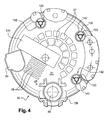
- assembly chimneys 132 In the embodiment of the figure 4 we replaced the assembly chimneys of the figure 3 by assembly chimneys 132 according to the invention. In this embodiment, it is sought to increase the reliability of the snap-fastening of the cover 30 on members, here the pins of the Figures 1 and 2 , integral with one of the flanges, here the rear bearing, which comprises the casing of the rotating electrical machine, here an alternator with internal ventilation of a motor vehicle with a heat engine as in the figure 3 .
- the number of assembly chimneys 132 is three in this embodiment. These chimneys 132 are distributed as at figure 3 . These chimneys 132 are integral with the bottom 31 of the cap 30 and extend perpendicularly to this bottom as the chimneys 32.
- the chimneys 132 have a wall defining the chimney.
- This cover 30 is in this embodiment moldable plastic, so that the chimneys 132 are molded easily with the bottom 31 of the cover 30 and are integral with it. As better visible in Figures 7 and 8 the chimneys 132 extend inside the hollow-shaped hood as in the figure 3 and in the figure 7 of the document US 6,798,094 supra.
- the chimneys 132 are generally of cylindrical shape and have, as at figure 2 , a ring-shaped head 34, which projects axially outwardly with respect to the bottom 31 as visible in FIGS. figures 5 , 7 and 8 .
- the walls of the chimneys are thus globally in the form of a cylindrical sleeve.
- the axis of axial symmetry of a chimney 132 coincides with the axis A of the stud 20 as visible at figure 8 .
- Each assembly chimney 132 and therefore each wall of the chimney, is internally equipped with three tongues 133 elastically deformable distributed circumferentially at 120 ° relative to each other.
- the tongues 133 are identical and separated from each other by centrally opening slots 139, like the slots 39.
- the distribution of the slots 139 and tabs 133 is circumferentially regular.
- At least one tongue 133 of an assembly chimney 132 has a loop of flexibility.
- tabs 133 have a loop of flexibility because the tabs 133 are identical and here are generally in the form of annular sector.
- This loop of flexibility is obtained, according to one characteristic, by inclining the tongue 133 relative to the axial axis of symmetry A of the chimney.
- the tongue 133 is directed towards the outside of the hood, that is to say in the direction of the upper end of the chimney delimited by the head 34 of the chimney.
- the tongue 133 is thus longer, more flexible and less brittle than the tongue 33 of the figure 2 , which extends radially, that is to say perpendicular to the axis A. Fixing the cover 30 is thus more reliable.
- This tongue 133 has a beveled free end 137 to cooperate with the first threaded portion 21 of the stud 20, which enters the chimney. As in figure 2 , the end 137 is intended to engage with a hollow of the thread of the portion 21.
- the tongue 133 is elastically deformable. It is deployable to cross the tops of the threads of the thread of the portion 21 and remain in final in a hollow of the thread of the threaded portion 21 during the latching operation of the cap 30 on the studs 20.
- Part 137 has in one embodiment a shape complementary to that of a hollow thread of the portion 21 for better attachment.
- the profile of the end 137 is here generally triangular
- the tongue 133 is connected, according to another characteristic, to the chimney 132, that is to say to the wall thereof, by a rounded portion 138 giving flexibility to the tongue 133 and making it less brittle.
- the tongue 133 forms an angle B with the wall of the chimney as visible in FIG. figure 7 . This angle is between 75 ° and 45 °.
- the tongue 133 forms a hook with the wall of the chimney 132.
- the portion 138 connects the tongue to the lower end of the chimney 132, that is to say at the base thereof located inside the hood.
- the base of the chimney 132 is no longer supported on the nut 22.
- This support is performed using a heel 135, which dorsally presents the tongue133.
- This heel came from molding with tongue 133.
- the heel 135 is interposed between the end 137 and the portion 138 constituting a rooting portion of the tongue 133 at the base of the chimney 132.
- This heel 135 is therefore close to the axis A.
- the size of the nut 22 can be reduced.
- the underside 149 of the heel is intended to bear on the upper face of the nut 22.
- the tabs 133 is finally immobilized because it is engaged by its end 137 with the thread of the portion 21 and bears by the lower face 149 of its heel 132 with the nut 22.
- the tongue 133, with a beveled free end 137 and a heel 135 adjacent this free end 137, is generally the end of a hook.
- the chimney 132 has internally at least one wall 140 radially oriented relative to the axis A of the chimney 132.
- the wall 140 is interposed circumferentially between two tabs 132. This wall 140 projects radially in the space between the tabs 133 of each other. In this embodiment, three walls 140 of radial orientation are provided.
- This arrangement makes it possible to keep the cover 30 radially well and in particular to withstand the phenomena of radial vibrations. This makes it possible to protect the tongues 133 and to further improve the reliability of the fixing of the cover on the flange of the rotating electrical machine.
- the walls 140 extend axially above the slots 139 separating the tabs from each other. These walls 140 came from molding with the wall of the chimney 132. They extend axially above the tabs 133.
- the shape of the slits 139 having a bottom provided with a flat part interposed between two inclined parts ( figure 6 ), makes it possible to easily obtain the walls and the tongues by molding.
- These walls 140 consist of a strip of material generally of rectangular section of high axial height depending on the axial height of the portion 21. The angular position of the walls 140, located above the slots, allows not to alter the flexibility of the tabs.
- the walls 140 are offset circumferentially with respect to the slits 139. To do this you have to modify the mold, which makes it more complicated. Nevertheless, in one embodiment, the walls may extend above the middle portion of the tongues.
- the chimney 132 Figures 4 to 9 is cylindrical in shape with circular section.
- the section of the cylindrical chimney is rectangular. This section can be square.
- the chimney has another shape. In all cases the axis of axial symmetry of the chimney extends perpendicular to the bottom 31.
- the present invention is not limited to the described embodiments.
- the number of chimneys 132 depends on the applications and in particular the size of the rotating electrical machine. This number may be one, two or more than three, for example four or six.
- the cover 30 therefore comprises at least one assembly chimney 132 with locking tabs 133.
- the chimneys 132 of the same hood are not necessarily the same size; at least one of the chimneys 132 may be smaller than those of other chimneys. This depends in particular on the space available at the bottom 31 of the hood 30 and therefore the location of the chimneys 132.
- the number of tongues 133 and walls 140 per chimney 132 also depends on the applications and in particular on the size of the rotating electrical machine and the number of chimneys 132. Thus in another embodiment there are provided two tongues 133 and two walls 140 per chimney 132. In still other embodiments this number is equal to four or six.
- the chimneys 132 of the same cover 30 not necessarily the same number of low walls 140 and tabs 133.
- at least one of the chimneys 132 may have a number of tabs 133 and walls 140 different from the other chimneys 132.
- at least one of the chimneys 132 of the same cover 30 may be without a wall 140.
- the hood is equipped with at least one chimney 32 of the figure 2 , so that the assembly chimneys of the same cover are not necessarily of the same type.
- at least one of the chimneys 132 of the figure 4 can be replaced by a fireplace 32 from the figure 3 .
- the number of walls 140 per chimney 132 is not necessarily equal to the number of tabs 133.
- the snap tabs 133 of the same chimney 132 do not necessarily have the same circumferential length, especially when the number of tabs per stack 132 is equal to four or six.
- the tabs 133 may belong to two series of tongues alternating circumferentially; one of the series being provided with tabs 133 of circumferential length greater than that of the tabs 133 of the other series.
- the presence of low walls 140 is not necessarily mandatory.
- the tabs 133 can be combined with the tabs 33 of the figure 2 .
- a tongue 33 is provided between two consecutive tongues 133 with or without the presence of walls. 140.
- the stud 20 does not necessarily have a dual function. Indeed the stud 20 also ensures through its washer 23 another function namely the maintenance of the sensor door in the case of the document WO 01/69762 and maintaining the connector and positive radiator in the case of documents US 6,798,094 and US 7,019,424 . Alternatively this stud can be dedicated only to the latching function of the hood. Alternatively this stud 20 can be replaced by a bolt screwing for example into the stud 401 of the rear bearing 14 of the alternator-starter of the figure 9 . In this case it is necessary to provide a recess in the inner face of the bearing 14 to accommodate the head of the bolt screw and to avoid any interference with the blades 45 of the fan 44.
- the tabs cooperate in this case with the threaded end of the bolt screw. It is also possible to use a threaded rod screw screwed into the extended stud 401 to serve as a bearing surface for the heels 135 when the sole function to be performed is the fastening of the cap 30. In this case, it is possible not to pierce the stud 401 but to extend it by a threaded or retaining ring portion, of the type of the rings 24 of the figure 1 , to engage the free ends of the tabs 133.
- the integral member of the flange may therefore be constituted by a stud advantageously molded with the flange.
- the tabs 133 do not necessarily cooperate with a stud.
- the integral member of the flange of the casing of the rotating electrical machine and belonging to the latching means for fixing the cover is therefore not necessarily a dowel. This member enters the chimney and in any case includes notches and recesses for receiving the free ends of the tongues.
- the recesses and notches belong to a thread or rings or any other embodiment. Similarly alternatively the heels rest on a shoulder belonging to a stud of the rear bearing.
- the hood is not necessarily hollow. It may consist in another embodiment in a simple cover resting on a flange of the flange concerned of the rotating electrical machine. This alternative machine can be cooled by circulation of a fluid inside at least one flange of its housing
- This flange is alternatively the front bearing.
- the rotating electrical machine is alternatively an electric motor.
- the hood is made of sheet metal.
- the flexibility of the tongues can be increased by extending the portion 138 by a strip of material cut in the wall of the chimney.
- the chimneys have another shape, such as frustoconical.
Applications Claiming Priority (1)
| Application Number | Priority Date | Filing Date | Title |
|---|---|---|---|
| FR0756797A FR2919769B1 (fr) | 2007-07-30 | 2007-07-30 | Capot de protection destine a etre fixe par encliquetage sur un flasque d'une machine electrique tournante et machine electrique tournante comportant un tel capot |
Publications (2)
| Publication Number | Publication Date |
|---|---|
| EP2020734A1 true EP2020734A1 (de) | 2009-02-04 |
| EP2020734B1 EP2020734B1 (de) | 2012-08-08 |
Family
ID=39391366
Family Applications (1)
| Application Number | Title | Priority Date | Filing Date |
|---|---|---|---|
| EP08159656A Active EP2020734B1 (de) | 2007-07-30 | 2008-07-03 | Schutzabdeckung zum Befestigen durch Einschnappen auf einem Flansch einer elektrischen umlaufenden Maschine und elektrische umlaufende Maschine, die eine solche Abdeckung umfasst |
Country Status (2)
| Country | Link |
|---|---|
| EP (1) | EP2020734B1 (de) |
| FR (1) | FR2919769B1 (de) |
Cited By (2)
| Publication number | Priority date | Publication date | Assignee | Title |
|---|---|---|---|---|
| DE102014226579A1 (de) * | 2014-12-19 | 2016-06-23 | Robert Bosch Gmbh | Schutzkappe für eine elektrische Maschine, insbesondere für einen Drehstromgenerator |
| WO2019025158A1 (fr) * | 2017-08-03 | 2019-02-07 | Valeo Equipements Electriques Moteur | Machine électrique tournante munie d'un capot de protection fixé par encliquetage |
Families Citing this family (1)
| Publication number | Priority date | Publication date | Assignee | Title |
|---|---|---|---|---|
| CN111371256A (zh) * | 2020-04-14 | 2020-07-03 | 上海法雷奥汽车电器系统有限公司 | 一种启动发电一体机 |
Citations (12)
| Publication number | Priority date | Publication date | Assignee | Title |
|---|---|---|---|---|
| FR2496353A1 (fr) * | 1980-12-11 | 1982-06-18 | Paris & Du Rhone | Dispositif de montage d'un ecran pare-chaleur pour machine tournante electrique |
| FR2532379A1 (fr) * | 1982-08-27 | 1984-03-02 | Usm Corp | Bouton-pression pour fixation sur un goujon |
| DE3305645A1 (de) * | 1983-02-18 | 1984-08-23 | Vdo Adolf Schindling Ag, 6000 Frankfurt | Motorgehaeuse |
| DE19630249A1 (de) * | 1995-08-01 | 1997-02-06 | Illinois Tool Works | Befestigungsclip |
| FR2743213A1 (fr) * | 1995-12-27 | 1997-07-04 | Valeo Systemes Dessuyage | Moteur a aimant permanent ayant un carter comportant deux parties fixees entre elles |
| EP1107431A2 (de) * | 1999-12-09 | 2001-06-13 | Denso Corporation | Lager-Schutzkappe für rotierende elektrische Maschinen |
| WO2001069762A1 (fr) | 2000-03-10 | 2001-09-20 | Valeo Equipements Electriques Moteur | Machine electrique tournante polyphasee |
| US6798094B2 (en) | 2000-10-06 | 2004-09-28 | Valeo Equipements Electriques Moteur | Rotary electric machine, and in particular motor vehicle alternator, comprising a stator elastically mounted in a heat-conductive resin |
| EP1551092A2 (de) * | 2003-12-30 | 2005-07-06 | Robert Bosch GmbH | Schutzkappe, insbesondere für einen Drehstromgenerator |
| US6978094B2 (en) | 2002-08-30 | 2005-12-20 | Konica Corporation | Image forming apparatus with a toner density sensor |
| US7019424B2 (en) | 2001-07-16 | 2006-03-28 | Valeo Equipements Electriques Moteur | Current rectifier assembly for rotating electrical machines, in particular motor vehicle alternator |
| US20060181167A1 (en) * | 2005-02-11 | 2006-08-17 | Bradfield Michael D | Method and apparatus for attachment of a cover for a dynamoelectric machine |
-
2007
- 2007-07-30 FR FR0756797A patent/FR2919769B1/fr not_active Expired - Fee Related
-
2008
- 2008-07-03 EP EP08159656A patent/EP2020734B1/de active Active
Patent Citations (12)
| Publication number | Priority date | Publication date | Assignee | Title |
|---|---|---|---|---|
| FR2496353A1 (fr) * | 1980-12-11 | 1982-06-18 | Paris & Du Rhone | Dispositif de montage d'un ecran pare-chaleur pour machine tournante electrique |
| FR2532379A1 (fr) * | 1982-08-27 | 1984-03-02 | Usm Corp | Bouton-pression pour fixation sur un goujon |
| DE3305645A1 (de) * | 1983-02-18 | 1984-08-23 | Vdo Adolf Schindling Ag, 6000 Frankfurt | Motorgehaeuse |
| DE19630249A1 (de) * | 1995-08-01 | 1997-02-06 | Illinois Tool Works | Befestigungsclip |
| FR2743213A1 (fr) * | 1995-12-27 | 1997-07-04 | Valeo Systemes Dessuyage | Moteur a aimant permanent ayant un carter comportant deux parties fixees entre elles |
| EP1107431A2 (de) * | 1999-12-09 | 2001-06-13 | Denso Corporation | Lager-Schutzkappe für rotierende elektrische Maschinen |
| WO2001069762A1 (fr) | 2000-03-10 | 2001-09-20 | Valeo Equipements Electriques Moteur | Machine electrique tournante polyphasee |
| US6798094B2 (en) | 2000-10-06 | 2004-09-28 | Valeo Equipements Electriques Moteur | Rotary electric machine, and in particular motor vehicle alternator, comprising a stator elastically mounted in a heat-conductive resin |
| US7019424B2 (en) | 2001-07-16 | 2006-03-28 | Valeo Equipements Electriques Moteur | Current rectifier assembly for rotating electrical machines, in particular motor vehicle alternator |
| US6978094B2 (en) | 2002-08-30 | 2005-12-20 | Konica Corporation | Image forming apparatus with a toner density sensor |
| EP1551092A2 (de) * | 2003-12-30 | 2005-07-06 | Robert Bosch GmbH | Schutzkappe, insbesondere für einen Drehstromgenerator |
| US20060181167A1 (en) * | 2005-02-11 | 2006-08-17 | Bradfield Michael D | Method and apparatus for attachment of a cover for a dynamoelectric machine |
Cited By (8)
| Publication number | Priority date | Publication date | Assignee | Title |
|---|---|---|---|---|
| DE102014226579A1 (de) * | 2014-12-19 | 2016-06-23 | Robert Bosch Gmbh | Schutzkappe für eine elektrische Maschine, insbesondere für einen Drehstromgenerator |
| WO2019025158A1 (fr) * | 2017-08-03 | 2019-02-07 | Valeo Equipements Electriques Moteur | Machine électrique tournante munie d'un capot de protection fixé par encliquetage |
| FR3069976A1 (fr) * | 2017-08-03 | 2019-02-08 | Valeo Equipements Electriques Moteur | Machine electrique tournante munie d'un capot de protection fixe par encliquetage |
| CN111066228A (zh) * | 2017-08-03 | 2020-04-24 | 法雷奥电机设备公司 | 设置有通过卡扣紧固而固定的保护盖的旋转电机 |
| JP2020529188A (ja) * | 2017-08-03 | 2020-10-01 | ヴァレオ エキプマン エレクトリク モトゥール | スナップ留めにより固定された保護カバーを備えた回転電気機械 |
| JP7013563B2 (ja) | 2017-08-03 | 2022-01-31 | ヴァレオ エキプマン エレクトリク モトゥール | スナップ留めにより固定された保護カバーを備えた回転電気機械 |
| CN111066228B (zh) * | 2017-08-03 | 2022-07-12 | 法雷奥电机设备公司 | 设置有通过卡扣紧固而固定的保护盖的旋转电机 |
| US11855507B2 (en) | 2017-08-03 | 2023-12-26 | Valeo Equipements Electriques Moteur | Rotary electrical machine provided with a protective cover secured by snap-fastening |
Also Published As
| Publication number | Publication date |
|---|---|
| FR2919769B1 (fr) | 2015-07-10 |
| FR2919769A1 (fr) | 2009-02-06 |
| EP2020734B1 (de) | 2012-08-08 |
Similar Documents
| Publication | Publication Date | Title |
|---|---|---|
| WO2001069762A1 (fr) | Machine electrique tournante polyphasee | |
| EP2020734B1 (de) | Schutzabdeckung zum Befestigen durch Einschnappen auf einem Flansch einer elektrischen umlaufenden Maschine und elektrische umlaufende Maschine, die eine solche Abdeckung umfasst | |
| WO2004040736A1 (fr) | Capot de protection destiné à être monté sur le palier arrière d'une machine électrique tournante, alternateur et alterno-démarreur comportant un tel capot | |
| EP2828532A1 (de) | Belüftungssystem | |
| EP1627450B1 (de) | Anordnung zum befestigen eines bond-steckers an einem stromausgangsanschluss, der an die gleichrichteinrichtung einer elektrischen drehmaschine befestigt ist | |
| FR2959364A1 (fr) | Ensemble porte-balais pour machine electrique, telle qu'un demarreur de vehicule automobile, cassette associee, et machine electrique pourvue d'un tel ensemble | |
| FR3069980B1 (fr) | Machine electrique tournante munie d'un deflecteur de liquide | |
| FR2951884A1 (fr) | Module de redressement de courant pour machine electrique tournante et machine electrique tournante comportant un tel module | |
| EP3662565B1 (de) | Elektrische drehmaschine mit einer durch schnappbefestigung befestigten schutzabdeckung | |
| EP3549237B1 (de) | Rotor für eine rotierende elektrische maschine | |
| EP3320602B1 (de) | Rotierende elektrische maschine mit einem schmiermittelreservoir zur schmierung eines wälzlagers und zur kühlung der maschine | |
| FR3098047A1 (fr) | Piece bobinee pour une machine electrique tournante destinee a un vehicule automobile | |
| EP3320604B1 (de) | Drehende elektrische maschine mit vorrichtung zum einstellen der winkelposition der welle | |
| WO2006111657A1 (fr) | Alternateur comprenant un roulement à bride de fixation | |
| EP3097634B1 (de) | Isolierungsvorrichtung für den kommutator der elektrischen maschine, zugehörige kommutator und lichtmaschine | |
| WO2022117539A1 (fr) | Collecteur pour machine électrique tournante | |
| WO2021180489A1 (fr) | Flasque plastique muni de murets de renfort pour une machine electrique tournante | |
| FR3056948B1 (fr) | Bloc de commande electrique pour garniture de portiere | |
| FR3132809A1 (fr) | Rotor pour une machine électrique tournante | |
| WO2021122489A1 (fr) | Rotor de machine électrique tournante | |
| FR3130908A1 (fr) | Groupe moto-ventilateur pour installation de chauffage, ventilation et/ou climatisation d’un véhicule automobile équipé d’un moyen de contact posé entre une coupelle et un moyeu. | |
| FR3111487A1 (fr) | Moteur électrique à moyens de découplage du rotor, pour dispositif de ventilation d’une installation de ventilation, climatisation et/ou chauffage d’un véhicule automobile | |
| FR2877419A1 (fr) | Bague d'adaptation et support pour groupe moto-ventilateur d'appareils de climatisation. | |
| FR3141013A1 (fr) | Ensemble de brosse de mise à la terre | |
| FR2954017A1 (fr) | Agencement de redressement de courant dote d'au moins deux modules pour machine electrique tournante et machine electrique tournante comportant un tel agencement |
Legal Events
| Date | Code | Title | Description |
|---|---|---|---|
| PUAI | Public reference made under article 153(3) epc to a published international application that has entered the european phase |
Free format text: ORIGINAL CODE: 0009012 |
|
| 17P | Request for examination filed |
Effective date: 20080703 |
|
| AK | Designated contracting states |
Kind code of ref document: A1 Designated state(s): AT BE BG CH CY CZ DE DK EE ES FI FR GB GR HR HU IE IS IT LI LT LU LV MC MT NL NO PL PT RO SE SI SK TR |
|
| AX | Request for extension of the european patent |
Extension state: AL BA MK RS |
|
| 17Q | First examination report despatched |
Effective date: 20090416 |
|
| AKX | Designation fees paid |
Designated state(s): AT BE BG CH CY CZ DE DK EE ES FI FR GB GR HR HU IE IS IT LI LT LU LV MC MT NL NO PL PT RO SE SI SK TR |
|
| GRAP | Despatch of communication of intention to grant a patent |
Free format text: ORIGINAL CODE: EPIDOSNIGR1 |
|
| GRAS | Grant fee paid |
Free format text: ORIGINAL CODE: EPIDOSNIGR3 |
|
| GRAA | (expected) grant |
Free format text: ORIGINAL CODE: 0009210 |
|
| AK | Designated contracting states |
Kind code of ref document: B1 Designated state(s): AT BE BG CH CY CZ DE DK EE ES FI FR GB GR HR HU IE IS IT LI LT LU LV MC MT NL NO PL PT RO SE SI SK TR |
|
| REG | Reference to a national code |
Ref country code: GB Ref legal event code: FG4D Free format text: NOT ENGLISH |
|
| REG | Reference to a national code |
Ref country code: CH Ref legal event code: EP Ref country code: AT Ref legal event code: REF Ref document number: 570186 Country of ref document: AT Kind code of ref document: T Effective date: 20120815 |
|
| REG | Reference to a national code |
Ref country code: IE Ref legal event code: FG4D Free format text: LANGUAGE OF EP DOCUMENT: FRENCH |
|
| REG | Reference to a national code |
Ref country code: DE Ref legal event code: R096 Ref document number: 602008017756 Country of ref document: DE Effective date: 20121004 |
|
| REG | Reference to a national code |
Ref country code: NL Ref legal event code: VDEP Effective date: 20120808 |
|
| REG | Reference to a national code |
Ref country code: AT Ref legal event code: MK05 Ref document number: 570186 Country of ref document: AT Kind code of ref document: T Effective date: 20120808 |
|
| REG | Reference to a national code |
Ref country code: LT Ref legal event code: MG4D Effective date: 20120808 |
|
| PG25 | Lapsed in a contracting state [announced via postgrant information from national office to epo] |
Ref country code: CY Free format text: LAPSE BECAUSE OF FAILURE TO SUBMIT A TRANSLATION OF THE DESCRIPTION OR TO PAY THE FEE WITHIN THE PRESCRIBED TIME-LIMIT Effective date: 20120808 Ref country code: AT Free format text: LAPSE BECAUSE OF FAILURE TO SUBMIT A TRANSLATION OF THE DESCRIPTION OR TO PAY THE FEE WITHIN THE PRESCRIBED TIME-LIMIT Effective date: 20120808 Ref country code: IS Free format text: LAPSE BECAUSE OF FAILURE TO SUBMIT A TRANSLATION OF THE DESCRIPTION OR TO PAY THE FEE WITHIN THE PRESCRIBED TIME-LIMIT Effective date: 20121208 Ref country code: NO Free format text: LAPSE BECAUSE OF FAILURE TO SUBMIT A TRANSLATION OF THE DESCRIPTION OR TO PAY THE FEE WITHIN THE PRESCRIBED TIME-LIMIT Effective date: 20121108 Ref country code: FI Free format text: LAPSE BECAUSE OF FAILURE TO SUBMIT A TRANSLATION OF THE DESCRIPTION OR TO PAY THE FEE WITHIN THE PRESCRIBED TIME-LIMIT Effective date: 20120808 Ref country code: LT Free format text: LAPSE BECAUSE OF FAILURE TO SUBMIT A TRANSLATION OF THE DESCRIPTION OR TO PAY THE FEE WITHIN THE PRESCRIBED TIME-LIMIT Effective date: 20120808 Ref country code: HR Free format text: LAPSE BECAUSE OF FAILURE TO SUBMIT A TRANSLATION OF THE DESCRIPTION OR TO PAY THE FEE WITHIN THE PRESCRIBED TIME-LIMIT Effective date: 20120808 |
|
| PG25 | Lapsed in a contracting state [announced via postgrant information from national office to epo] |
Ref country code: LV Free format text: LAPSE BECAUSE OF FAILURE TO SUBMIT A TRANSLATION OF THE DESCRIPTION OR TO PAY THE FEE WITHIN THE PRESCRIBED TIME-LIMIT Effective date: 20120808 Ref country code: GR Free format text: LAPSE BECAUSE OF FAILURE TO SUBMIT A TRANSLATION OF THE DESCRIPTION OR TO PAY THE FEE WITHIN THE PRESCRIBED TIME-LIMIT Effective date: 20121109 Ref country code: PT Free format text: LAPSE BECAUSE OF FAILURE TO SUBMIT A TRANSLATION OF THE DESCRIPTION OR TO PAY THE FEE WITHIN THE PRESCRIBED TIME-LIMIT Effective date: 20121210 Ref country code: SI Free format text: LAPSE BECAUSE OF FAILURE TO SUBMIT A TRANSLATION OF THE DESCRIPTION OR TO PAY THE FEE WITHIN THE PRESCRIBED TIME-LIMIT Effective date: 20120808 Ref country code: SE Free format text: LAPSE BECAUSE OF FAILURE TO SUBMIT A TRANSLATION OF THE DESCRIPTION OR TO PAY THE FEE WITHIN THE PRESCRIBED TIME-LIMIT Effective date: 20120808 Ref country code: PL Free format text: LAPSE BECAUSE OF FAILURE TO SUBMIT A TRANSLATION OF THE DESCRIPTION OR TO PAY THE FEE WITHIN THE PRESCRIBED TIME-LIMIT Effective date: 20120808 |
|
| PG25 | Lapsed in a contracting state [announced via postgrant information from national office to epo] |
Ref country code: NL Free format text: LAPSE BECAUSE OF FAILURE TO SUBMIT A TRANSLATION OF THE DESCRIPTION OR TO PAY THE FEE WITHIN THE PRESCRIBED TIME-LIMIT Effective date: 20120808 |
|
| PG25 | Lapsed in a contracting state [announced via postgrant information from national office to epo] |
Ref country code: EE Free format text: LAPSE BECAUSE OF FAILURE TO SUBMIT A TRANSLATION OF THE DESCRIPTION OR TO PAY THE FEE WITHIN THE PRESCRIBED TIME-LIMIT Effective date: 20120808 Ref country code: CZ Free format text: LAPSE BECAUSE OF FAILURE TO SUBMIT A TRANSLATION OF THE DESCRIPTION OR TO PAY THE FEE WITHIN THE PRESCRIBED TIME-LIMIT Effective date: 20120808 Ref country code: DK Free format text: LAPSE BECAUSE OF FAILURE TO SUBMIT A TRANSLATION OF THE DESCRIPTION OR TO PAY THE FEE WITHIN THE PRESCRIBED TIME-LIMIT Effective date: 20120808 Ref country code: ES Free format text: LAPSE BECAUSE OF FAILURE TO SUBMIT A TRANSLATION OF THE DESCRIPTION OR TO PAY THE FEE WITHIN THE PRESCRIBED TIME-LIMIT Effective date: 20121119 Ref country code: RO Free format text: LAPSE BECAUSE OF FAILURE TO SUBMIT A TRANSLATION OF THE DESCRIPTION OR TO PAY THE FEE WITHIN THE PRESCRIBED TIME-LIMIT Effective date: 20120808 |
|
| PG25 | Lapsed in a contracting state [announced via postgrant information from national office to epo] |
Ref country code: SK Free format text: LAPSE BECAUSE OF FAILURE TO SUBMIT A TRANSLATION OF THE DESCRIPTION OR TO PAY THE FEE WITHIN THE PRESCRIBED TIME-LIMIT Effective date: 20120808 Ref country code: IT Free format text: LAPSE BECAUSE OF FAILURE TO SUBMIT A TRANSLATION OF THE DESCRIPTION OR TO PAY THE FEE WITHIN THE PRESCRIBED TIME-LIMIT Effective date: 20120808 |
|
| PLBE | No opposition filed within time limit |
Free format text: ORIGINAL CODE: 0009261 |
|
| STAA | Information on the status of an ep patent application or granted ep patent |
Free format text: STATUS: NO OPPOSITION FILED WITHIN TIME LIMIT |
|
| 26N | No opposition filed |
Effective date: 20130510 |
|
| PG25 | Lapsed in a contracting state [announced via postgrant information from national office to epo] |
Ref country code: BG Free format text: LAPSE BECAUSE OF FAILURE TO SUBMIT A TRANSLATION OF THE DESCRIPTION OR TO PAY THE FEE WITHIN THE PRESCRIBED TIME-LIMIT Effective date: 20121108 |
|
| REG | Reference to a national code |
Ref country code: DE Ref legal event code: R097 Ref document number: 602008017756 Country of ref document: DE Effective date: 20130510 |
|
| BERE | Be: lapsed |
Owner name: VALEO EQUIPEMENTS ELECTRIQUES MOTEUR Effective date: 20130731 |
|
| PG25 | Lapsed in a contracting state [announced via postgrant information from national office to epo] |
Ref country code: MC Free format text: LAPSE BECAUSE OF FAILURE TO SUBMIT A TRANSLATION OF THE DESCRIPTION OR TO PAY THE FEE WITHIN THE PRESCRIBED TIME-LIMIT Effective date: 20120808 |
|
| REG | Reference to a national code |
Ref country code: CH Ref legal event code: PL |
|
| GBPC | Gb: european patent ceased through non-payment of renewal fee |
Effective date: 20130703 |
|
| REG | Reference to a national code |
Ref country code: IE Ref legal event code: MM4A |
|
| PG25 | Lapsed in a contracting state [announced via postgrant information from national office to epo] |
Ref country code: LI Free format text: LAPSE BECAUSE OF NON-PAYMENT OF DUE FEES Effective date: 20130731 Ref country code: CH Free format text: LAPSE BECAUSE OF NON-PAYMENT OF DUE FEES Effective date: 20130731 Ref country code: BE Free format text: LAPSE BECAUSE OF NON-PAYMENT OF DUE FEES Effective date: 20130731 Ref country code: GB Free format text: LAPSE BECAUSE OF NON-PAYMENT OF DUE FEES Effective date: 20130703 |
|
| PG25 | Lapsed in a contracting state [announced via postgrant information from national office to epo] |
Ref country code: IE Free format text: LAPSE BECAUSE OF NON-PAYMENT OF DUE FEES Effective date: 20130703 |
|
| PG25 | Lapsed in a contracting state [announced via postgrant information from national office to epo] |
Ref country code: MT Free format text: LAPSE BECAUSE OF FAILURE TO SUBMIT A TRANSLATION OF THE DESCRIPTION OR TO PAY THE FEE WITHIN THE PRESCRIBED TIME-LIMIT Effective date: 20120808 |
|
| PG25 | Lapsed in a contracting state [announced via postgrant information from national office to epo] |
Ref country code: LU Free format text: LAPSE BECAUSE OF NON-PAYMENT OF DUE FEES Effective date: 20130703 Ref country code: HU Free format text: LAPSE BECAUSE OF FAILURE TO SUBMIT A TRANSLATION OF THE DESCRIPTION OR TO PAY THE FEE WITHIN THE PRESCRIBED TIME-LIMIT; INVALID AB INITIO Effective date: 20080703 |
|
| REG | Reference to a national code |
Ref country code: FR Ref legal event code: PLFP Year of fee payment: 9 |
|
| REG | Reference to a national code |
Ref country code: FR Ref legal event code: PLFP Year of fee payment: 10 |
|
| REG | Reference to a national code |
Ref country code: FR Ref legal event code: PLFP Year of fee payment: 11 |
|
| P01 | Opt-out of the competence of the unified patent court (upc) registered |
Effective date: 20230528 |
|
| PGFP | Annual fee paid to national office [announced via postgrant information from national office to epo] |
Ref country code: TR Payment date: 20230620 Year of fee payment: 16 |
|
| PGFP | Annual fee paid to national office [announced via postgrant information from national office to epo] |
Ref country code: FR Payment date: 20230727 Year of fee payment: 16 Ref country code: DE Payment date: 20230712 Year of fee payment: 16 |