EP3320604B1 - Drehende elektrische maschine mit vorrichtung zum einstellen der winkelposition der welle - Google Patents
Drehende elektrische maschine mit vorrichtung zum einstellen der winkelposition der welle Download PDFInfo
- Publication number
- EP3320604B1 EP3320604B1 EP16745796.9A EP16745796A EP3320604B1 EP 3320604 B1 EP3320604 B1 EP 3320604B1 EP 16745796 A EP16745796 A EP 16745796A EP 3320604 B1 EP3320604 B1 EP 3320604B1
- Authority
- EP
- European Patent Office
- Prior art keywords
- electric machine
- rotary electric
- shaft
- machine
- casing
- Prior art date
- Legal status (The legal status is an assumption and is not a legal conclusion. Google has not performed a legal analysis and makes no representation as to the accuracy of the status listed.)
- Active
Links
- 230000008878 coupling Effects 0.000 claims description 12
- 238000010168 coupling process Methods 0.000 claims description 12
- 238000005859 coupling reaction Methods 0.000 claims description 12
- 238000003780 insertion Methods 0.000 claims description 9
- 230000037431 insertion Effects 0.000 claims description 9
- 238000001816 cooling Methods 0.000 claims description 8
- 239000000110 cooling liquid Substances 0.000 claims description 7
- 239000007788 liquid Substances 0.000 claims description 5
- 230000001050 lubricating effect Effects 0.000 claims description 5
- 238000004804 winding Methods 0.000 description 12
- 239000000314 lubricant Substances 0.000 description 6
- 239000002826 coolant Substances 0.000 description 5
- 229910052751 metal Inorganic materials 0.000 description 4
- 239000002184 metal Substances 0.000 description 4
- 230000002441 reversible effect Effects 0.000 description 4
- 238000002485 combustion reaction Methods 0.000 description 3
- 230000005484 gravity Effects 0.000 description 3
- 238000002347 injection Methods 0.000 description 2
- 239000007924 injection Substances 0.000 description 2
- 238000003475 lamination Methods 0.000 description 2
- 238000003466 welding Methods 0.000 description 2
- 230000005540 biological transmission Effects 0.000 description 1
- 210000003298 dental enamel Anatomy 0.000 description 1
- 239000000839 emulsion Substances 0.000 description 1
- 239000012530 fluid Substances 0.000 description 1
- 239000004519 grease Substances 0.000 description 1
- 238000009396 hybridization Methods 0.000 description 1
- 238000009413 insulation Methods 0.000 description 1
- 238000005461 lubrication Methods 0.000 description 1
- 230000002093 peripheral effect Effects 0.000 description 1
- 229910052761 rare earth metal Inorganic materials 0.000 description 1
- 150000002910 rare earth metals Chemical class 0.000 description 1
- XLYOFNOQVPJJNP-UHFFFAOYSA-N water Substances O XLYOFNOQVPJJNP-UHFFFAOYSA-N 0.000 description 1
- 229910000859 α-Fe Inorganic materials 0.000 description 1
Images


Classifications
-
- H—ELECTRICITY
- H02—GENERATION; CONVERSION OR DISTRIBUTION OF ELECTRIC POWER
- H02K—DYNAMO-ELECTRIC MACHINES
- H02K7/00—Arrangements for handling mechanical energy structurally associated with dynamo-electric machines, e.g. structural association with mechanical driving motors or auxiliary dynamo-electric machines
- H02K7/006—Structural association of a motor or generator with the drive train of a motor vehicle
Definitions
- the present invention relates to a rotating electric machine provided with a means for adjusting the angular position of the shaft.
- the invention finds a particularly advantageous, but not exclusive, application with high-power reversible electric machines that can operate in alternator mode and in motor mode.
- rotating electrical machines comprise a stator and a rotor secured to a shaft.
- the rotor may be integral with a driving and/or driven shaft and may belong to a rotating electric machine in the form of an alternator, an electric motor, or a reversible machine that can operate in both modes.
- the stator is mounted in a housing configured to rotate the shaft, for example via bearings.
- the rotor comprises a body formed by a stack of sheet metal sheets held in the form of a package by means of a suitable fastening system, such as rivets passing axially through the body of the rotor right through.
- the rotor comprises poles formed for example by permanent magnets housed in cavities formed in the magnetic mass of the rotor, as described for example in the document EP0803962 .
- the poles are formed by coils wound around the arms of the rotor.
- the stator comprises a body consisting of a stack of thin laminations forming a crown, the inner face of which is provided with slots open inwards to receive phase windings. These windings pass through the notches of the body of the stator and form buns projecting on either side of the body of the stator.
- the phase windings are obtained for example from a continuous wire covered with enamel or from conductive elements in the form of pins connected together by welding. These windings are polyphase windings connected in star or in triangle whose outputs are connected to a voltage rectifying bridge.
- a high-power reversible rotating electrical machine can be integrated into various elements of the traction chain.
- the machine can thus be coupled to a gearbox, a clutch, or a differential of the vehicle.
- the electric machine is then able to operate in an alternator mode in particular to supply energy to the battery and to the on-board network of the vehicle, and in a motor mode, not only to ensure the starting of the internal combustion engine, but also to participate traction of the vehicle alone or in combination with the internal combustion engine.
- the drive of the shaft via the adjustment portion made for example in the cylindrical side face of the shaft is separate from the drive performed by the active components of the machine and separate from the drive that can be performed by an external element coupled to the machine via the coupling member.
- This drive via the adjustment portion is intended to be carried out using a tool external to the casing of the machine which is manipulated by an operator and, if necessary, by a robot on the assembly line.
- the invention thus makes it possible to achieve an angular positioning under control of the shaft, in particular to ensure mechanical coupling with the host element, for example by meshing between a pinion carried by the shaft of the machine and a corresponding pinion of the host element.
- the stator surrounds the rotor.
- the rotor is mounted on the shaft.
- said adjustment portion projects in relation to the casing of the machine. This allows access to this portion by a tool while the machine is mounted in the host element.
- said adjustment portion comprises at least one flat.
- the portion may project relative to the portion carried by the bearing.
- said adjustment portion comprises a plurality of flats, in particular between two and six flats.
- said adjustment portion comprises a particularly axial recess, arranged in the side face of the shaft, configured to allow said shaft to be driven in rotation.
- the hollow may for example have a section of polygonal shape or any other shape suitable for the application.
- said adjustment portion comprises a hole extending transversely relative to said shaft capable of receiving a pin of corresponding shape.
- the invention allows the assembly of an electric machine cooled by a lubricating liquid, when it is intended to be integrated into one of the elements of the traction chain of a motor vehicle.
- the cooling circuit is arranged to cool the rotor and/or the stator.
- said shaft is configured so that a lubricating liquid, such as oil, can circulate inside it to lubricate and/or cool said rotating electrical machine.
- a lubricating liquid such as oil
- the casing comprises an element for axially guiding said rotating electrical machine, in particular during its insertion into said envelope of said host element, and an element for centering said rotating electrical machine with respect to said envelope of said host element.
- the casing comprises an indexing member arranged to allow the angular indexing of said rotating electrical machine in a predetermined position, in particular when it is inserted into the casing of said host element intended to be coupled with said rotating electrical machine.
- said rotating electrical machine comprises a plurality of channels extending between said stator and said casing, and in that said casing comprises a plurality of openings each opening via one of their ends outside of said electrical machine rotating and by another of their ends in a channel.
- the casing comprises front and rear bearings assembled together.
- the front bearing comprises a transverse wall, a nose extending projecting relative to the transverse wall and a cylindrical wall extending from the outer periphery of the transverse wall.
- the plurality of channels extends between the stator and the cylindrical wall.
- the casing defines a cylindrical wall
- the machine comprises a plurality of channels extending between the stator and the cylindrical wall of the casing.
- the casing comprises a plurality of openings each opening via one of their ends outside of said rotary electrical machine and via another of their ends into a channel of the plurality of channels.
- a power of the machine may be between 10 kW and 50 kW.
- an outer diameter of the rotor is between 8 and 14 cm, in particular between 10 and 12 cm, and is preferably 11 cm.
- an outer diameter of the stator is between 10 and 20 cm, in particular between 13 and 18 cm, and is preferably 15 cm.
- the machine comprises a cooling circuit arranged in particular to allow the flow of a cooling liquid, for example an oil, between the casing and the stator.
- a cooling liquid for example an oil
- the cooling circuit is arranged to allow the flow of a cooling liquid in an axial bore made in the shaft.
- the invention also relates to an assembly characterized in that it comprises an envelope of a host element and a rotary electrical machine as defined above inserted in said envelope.
- the host element comprises a pinion for coupling with the corresponding pinion of the rotating electrical machine.
- the host element is an element of a traction chain of a motor vehicle, for example a gearbox, or a differential, or a clutch.
- a "front” element is located on the side of the coupling member of the machine, such as a pinion or a pulley, with the host element and that a "rear” is located on the opposite side.
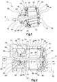
- the figure 1 shows a rotating electrical machine 10 comprising a polyphase stator 11 surrounding an X-axis rotor 12 mounted on a shaft 13.
- the stator 11 is carried by a casing 16 configured to carry the shaft 13 in rotation.
- the stator 11 surrounds the rotor 12 with the presence of an air gap between the internal periphery of the stator 11 and the external periphery of the rotor 12.
- This electric machine 10 is intended to be installed inside an envelope 21 of a host element 20 visible in figure 2 belonging to a motor vehicle traction chain.
- the host element 20 intended to be mechanically coupled with the electric machine 10 could for example take the form of a clutch, a gearbox, or a differential.
- the shaft 13 carries at one of its ends a coupling member 24, such as a pinion, intended to mesh with a corresponding pinion (not shown) of the host element 20 in order to ensure a transmission torque between the two elements.
- the pinion 24 may be an added pinion mounted on the shaft 13 or a pinion of another type.
- the coupling member 24 may consist of a pulley intended to cooperate with a belt.
- the machine 10 is able to operate in an alternator mode in particular to supply energy to the battery and to the on-board network of the vehicle, and in a motor mode to participate in the traction of the vehicle alone or in combination with the combustion engine.
- the rotor 12 comprises a body 25 formed by a stack of sheet metal sheets. These sheets of metal sheets are held in the form of a stack of metal sheets by means of a suitable fastening system 26, such as rivets passing axially through the rotor 12 right through.
- Permanent magnets 27 are implanted in openings of the body.
- the magnets 27 may be made of rare earth or ferrite depending on the applications and the desired power of the machine 10.
- the poles of the rotor 12 may be formed by coils.
- the stator 11 comprises a body 30 in the form of a stack of laminations provided with notches, for example of the semi-closed type, equipped with notch insulation for mounting the winding 31 of the stator 11.
- the winding 31 comprises a set of phase windings passing through the notches of the body of the stator 11 and forming front 32 and rear 33 buns projecting from either side of the body 30 of the stator 11.
- the phase windings are obtained here at from conductive elements in the form of pins connected together for example by welding. These windings are for example three-phase windings connected in one or more stars or in one or more triangles.
- the outputs of the phase windings are connected to a switching bridge and/or rectifier and/or to an inverter comprising diodes or transistors of the MOSFET type, in particular when a reversible machine is involved.
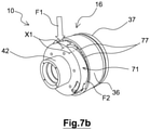
- the housing 16 has front 36 and rear 37 bearings assembled together.
- the bearings 36 and 37 are hollow in shape and each carry in their center a ball bearing 38, 39 for the rotational mounting of the shaft 13.
- the bearing is a magnetic bearing.
- the front bearing 36 comprises a nose 42 projecting from a transverse wall 43.
- a wall 44 of cylindrical shape extends from the outer periphery of the transverse wall 43.
- the rear bearing 37 comprises a transverse wall 47 comprising a through hole in its center to allow the passage of the shaft 13 and provided with an annular seat 48 intended to support the outer race of the rear bearing 39.
- the rear bearing 37 also comprises a cylindrical wall 49 extending from an outer periphery of the transverse wall 43.
- the rear bearing 37 is fixed to the front bearing 36 by means of fixing members 51, such as screws or rivets, passing through openings made in an annular flange 50 coming from the wall 49 to cooperate with bores made in the thickness of the cylindrical wall 44 of the front bearing 36 (cf. figure 2 ).
- the nose 42 is intended to cooperate with a hollow sleeve 56 of corresponding shape coming from a wall 57, in particular internal transverse, of the casing 21.
- the nose 42 forms an axial guide element of the machine 10 relative to the host element 20, during its insertion inside the sleeve 56.
- the axial positioning of the machine 10 inside the casing 21 is controlled by the outer surface of the transverse wall 43 of the bearing front 36 constituting an axial abutment intended to bear against the corresponding transverse wall 57 of the casing 21.
- the surface forming an abutment is contained in a plane P1 perpendicular to the axis X of the machine 10.
- the nose 42 forms an element for centering the machine 10 with respect to the casing 21 of the host element 20.
- the nose 42 comprises on the outer periphery a fitted surface 60 with respect to the sleeve 56, for example by an adjustment comprised between 1/100 and 3/100 of a millimeter, for example of the H7g6 type.
- a section of the nose 42 perpendicular to the axis of the casing 16 (corresponding to the axis X) intersecting the fitted surface 60 has a surface strictly greater than a surface of another section of the nose 42.
- the nose 42 comprises a wall of cylindrical shape delimiting a space allowing the passage of the shaft 13.
- the nose 42 also carries the outer race of the front bearing 38 cooperating with a corresponding bearing surface formed in the internal periphery of the nose 42.
- the area of the largest section of the nose 42 is strictly less than any area of a section of the machine 10 contained in a plane perpendicular to the axis X of the machine 10 intersecting the stator 11.
- the largest outer diameter of nose 42 located at fitted surface 60 is less than the outer diameter of any other portion of front bearing 36 or rear bearing 37.
- the functions of guiding and centering the machine 10 are separated and carried out by two distinct elements.
- a second portion 62 of the front bearing 36 also ensures the centering of the machine 10 with respect to the casing 21.
- this second portion 62 is constituted by a part of the cylindrical wall 44 of the front bearing 36 located at the level of the connection between the two bearings 36, 37.
- This portion 62 comprises a surface adjusted with respect to a corresponding internal cylindrical face of the casing 21, for example by an adjustment comprised between 1/100 and 3/100 of a millimeter, by example of type H7g6.
- a centering portion of the cylindrical wall 49 of the rear bearing 37 ensures the centering of the machine 10 with respect to the casing 21.
- This portion comprises a surface adjusted with respect to a corresponding internal cylindrical face of the casing 21, for example by an adjustment comprised between 1/100 and 3/100 of a millimeter, for example of the H7g6 type.
- the shaft 13 has in its central part splines for its force fitting inside the central bore of the rotor body 25.
- an adjustment portion 65 allows shaft 13 to be driven in rotation during the insertion of the machine 10 into the casing 21. This facilitates the coupling of the machine 10 with the host element 20 by allowing, for rotation of the shaft 13 via the portion 65, the insertion of the teeth of the pinion 24 carried by the shaft 13 between the spaces of the teeth of the corresponding pinion of the host element 20.
- the adjustment portion 65 projects in relation to the casing 16.
- the adjustment portion 65 comprises at least one flat intended to cooperate with a tool of corresponding shape. This tool can be manipulated manually by an operator or, if necessary, automatically by a robot in the assembly line.
- the adjustment portion 65 comprises a plurality of flats, in particular between two and six flats.
- the adjustment portion 65 comprises a particularly axial recess, arranged in the side face of the shaft 13, configured to allow the shaft 13 to be driven in rotation.
- the recess may for example have a polygonal or any other form suitable for the application.
- the adjustment portion 65 comprises a hole extending transversely relative to said shaft 13 capable of receiving a pin of corresponding shape.
- the electric machine 10 is cooled by means of a cooling circuit 68 arranged to allow in particular the flow of a cooling liquid, in this case oil, between the casing 16 and the stator body 30, in the direction of the X axis.
- a cooling liquid in this case oil
- the cooling circuit 68 comprises a pump 69 for injecting coolant into a distribution chamber 70.
- the distribution chamber 70 of generally annular shape is delimited by a part of an internal face 72 of the envelope 21 and part of the wall 44 of the front bearing 36.
- the front bearing 36 comprises, in the cylindrical wall 44, a peripheral recess 71 of reduced diameter compared to the rest of the cylindrical wall 44.
- the chamber 70 is delimited by the outer face of this recess 71 as well as by a side internal vis-à-vis the casing 21.
- the chamber 70 extends beyond the recess 71 in an annular space delimited by the outer periphery of the cylindrical portion of the front bearing 36 and the internal face 72 of the casing 21.
- the chamber 70 is hermetically closed on the side of its rear end by a seal 75 positioned inside a groove 78 formed in the outer periphery of the front bearing 36.
- a seal 75 positioned inside a groove 78 formed in the outer periphery of the front bearing 36.
- the outer surface of the wall transverse 43 bears against a corresponding flat surface of the transverse wall 57 of the casing 21 to seal the chamber 70.
- the chamber 70 is in communication with a plurality of channels 76 (cf. figure 1 ) extending axially between the stator 11 and the housing 16 for the passage of the coolant.
- These channels 76 are angularly distributed in a regular manner over the circumference of the stator 11.
- these channels 76 are formed by grooves managed in an outer periphery of the stator body 11 and closed radially by the inner face of the casing 16 .
- the housing 16 comprises a plurality of openings 77 each opening by one of their ends outside the machine 10 in the distribution chamber 70 and by another of their ends on the side of the channels 76.
- the plurality of openings 77 is distributed angularly along a perimeter of the casing 16.
- a surface of the section of the different openings 77 varies according to an angular position of the openings 77, so that the cooling liquid circulates in each channel 76 with substantially the same pressure.
- the further one moves away from the oil injection zone 80 inside the chamber 70 the more the surface of the sections of the various openings 77 increases.
- the openings 77 have an increasing section.
- the openings 77 each have an axis X1 (cf. figure 7b ) extending parallel to the axis X of the machine 10 corresponding to the direction of flow of the coolant inside the channels 76.
- an oil injection direction along the arrow F1 is inclined relative to the axis X1 of the openings 77, for example at an angle of at least 40°.
- the liquid in the distribution chamber 70 is under pressure and preferably circulates at a flow rate of between 3 and 11 liters/minute.
- the oil injected along the arrow F1 is evenly distributed inside the openings 77 on the circumference of the chamber 77 along the arrow F2 to flow axially inside the channels 76 along the arrows F3 on the circumference of the stator 11 in order to effectively cool the machine 10.
- the oil also circulates in an axial bore 83 made in the shaft 13 of the rotor 12 and in ducts 84 issuing from said bore 83 opening out towards the two axial end faces of the rotor 12.
- the shaft 13 also comprises at least an oil outlet 85 opening in front of a tank 88 formed in the housing 16.
- This tank 88 is adapted to receive the coolant also acting as a lubricant to ensure the lubrication of the front bearing 38.
- the tank 88 is positioned in the lower part of the machine 10 so that the lubricant can be stored in the tank 88 by gravity.
- Reservoir 88 is configured to promote the flow of excess lubricant towards bearing 38 when reservoir 88 is full.
- Reservoir 88 is delimited by a bottom 89, a first flange 91 formed by an annular collar of radial orientation which comes from an internal periphery of nose 42, and a second flange 92 formed by the outer ring of bearing 38.
- a portion of the bearing 38 is thus in fluidic contact with the lubricant of the reservoir 88, that is to say that at least a part of the bearing 38 is in direct contact with the oil of the reservoir 88.
- the first rim 91 is configured to allow the flow of lubricant from the reservoir 88 to the bearing 38, in particular by gravity, when the machine 10 is mounted in the host element 20.
- the height H1 of the first rim relative to the bottom 89 is greater than the height H2 of the second rim 92 relative to the bottom 89.
- the bottom 89 is slightly raised relative to the bearing surface of the inner ring of the bearing 38 and extends along its width in a direction of the axis X of the machine 10.
- the bearing 38 has no flange.
- the bearing 38 is preferably degreased beforehand so that the oil can easily pass through it without interference with the grease which it contains by default and which will have been removed as a precaution.
- the cooling circuit 68 operates in a closed loop, in such a way that the oil is taken by the pump 69 from a reservoir 95 external to the machine 10 and is recovered after circulation in the machine 10 in this reservoir 95.
- the rear bearing 37 has openings 96 distributed around its circumference and clearly visible on the figure 6 .
- the landing front 36 also has an opening 97 to allow oil to exit to tank 95.
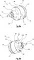
- the casing 16 comprises an indexing member 100 arranged to allow the angular indexing of the machine 10 by compared to the envelope 21 during its insertion into the envelope 21.
- the indexing member 100 shown on the figure 3b , 4, and 5 consists of a stud made on the transverse wall 43 of the front bearing 36.
- This stud 100 is arranged to be inserted into a correspondingly shaped bore of the host element 20.
- the stud 100 may be of the type attached to the casing 16 or, alternatively, being made in one piece with casing 16. Stud 100 is also configured to allow machine 10 to be locked in rotation. forces developed by the electric machine 10 in operation.
- the cooling liquid also acting as a lubricant may take the form of an emulsion of oil and water.
- a power of the machine 10 may be between 10kW and 50kW.
- An outside diameter of the rotor 12 is between 8 and 14 cm, in particular between 10 and 12 cm, and is preferably 11 cm.
- An outside diameter of the stator 11 is between 10 and 20 cm, in particular between 13 and 18 cm, and is preferably 15 cm.
Landscapes
- Engineering & Computer Science (AREA)
- Power Engineering (AREA)
- Motor Or Generator Cooling System (AREA)
- Motor Or Generator Frames (AREA)
- Hybrid Electric Vehicles (AREA)
- Arrangement Or Mounting Of Propulsion Units For Vehicles (AREA)
- Connection Of Motors, Electrical Generators, Mechanical Devices, And The Like (AREA)
Claims (8)
- Drehende elektrische Maschine (10), insbesondere für ein Kraftfahrzeug, welche aufweist:- einen Stator (11) und einen Rotor (12), die im Inneren eines Gehäuses (16) angebracht sind,- eine Welle (13), welche aufweist:- an ihrem ersten Ende ein Kupplungsorgan (24), das ein Ritzel aufweist, insbesondere zur Kupplung der drehenden elektrischen Maschine (10) mit einem entsprechenden Ritzel eines aufnehmenden Elements (20), und- an ihrem zweiten Ende einen Einstellabschnitt (65), der dazu eingerichtet ist, einen Drehantrieb der Welle (13) zu ermöglichen, insbesondere bei einem Einsetzen der drehenden elektrischen Maschine (10) in eine Hülle (21) des aufnehmenden Elements (20),wobei das Gehäuse (16) ein Indexierungsorgan (100) aufweist, das dazu eingerichtet ist, die Winkelindexierung der drehenden elektrischen Maschine (10) in einer vorbestimmten Position bei ihrem Einsetzen in die Hülle (21) des aufnehmenden Elements (20) zu ermöglichen, das dazu bestimmt ist, mit der drehenden elektrischen Maschine (10) gekuppelt zu werden,
wobei die drehende elektrische Maschine dadurch gekennzeichnet ist, dass sie umfasst:- einen Kühlkreislauf, der dazu eingerichtet ist, insbesondere das Fließen einer Schmier- und/oder Kühlflüssigkeit, zum Beispiel eines Öls, im Inneren der drehenden elektrischen Maschine (10) zu ermöglichen. - Drehende elektrische Maschine nach einem der vorhergehenden Ansprüche, dadurch gekennzeichnet, dass sich der Einstellabschnitt (65) in Bezug auf das Gehäuse (16) der Maschine vorspringend erstreckt.
- Drehende elektrische Maschine nach einem der vorhergehenden Ansprüche, dadurch gekennzeichnet, dass der Einstellabschnitt (65) wenigstens eine Abflachung aufweist.
- Drehende elektrische Maschine nach einem der vorhergehenden Ansprüche, dadurch gekennzeichnet, dass der Einstellabschnitt (65) eine Vertiefung aufweist, die dafür ausgelegt ist, den Drehantrieb der Welle (13) zu ermöglichen.
- Drehende elektrische Maschine nach einem der vorhergehenden Ansprüche, dadurch gekennzeichnet, dass der Einstellabschnitt (65) ein sich quer bezüglich der Welle (13) erstreckendes Loch aufweist, das geeignet ist, einen Stift mit entsprechender Form aufzunehmen.
- Drehende elektrische Maschine nach einem der vorhergehenden Ansprüche, dadurch gekennzeichnet, dass die Welle (13) dafür ausgelegt ist, dass eine Schmierflüssigkeit, wie etwa ein Öl, im Inneren derselben zirkulieren kann, um die drehende elektrische Maschine zu schmieren und/oder zu kühlen.
- Drehende elektrische Maschine nach einem der vorhergehenden Ansprüche, dadurch gekennzeichnet, dass sie eine Vielzahl von Kanälen (76) aufweist, die sich zwischen dem Stator und dem Gehäuse (16) erstrecken, und dadurch, dass das Gehäuse (16) eine Vielzahl von Öffnungen (77) aufweist, die jeweils mit einem ihrer Enden auf der Außenseite der drehenden elektrischen Maschine (10) und mit einem anderen ihrer Enden in einen Kanal (76) münden.
- Anordnung, dadurch gekennzeichnet, dass sie eine Hülle (21) eines aufnehmenden Elements (20) und eine drehende elektrische Maschine (10), wie nach einem der vorhergehenden Ansprüche definiert, die in die Hülle (21) eingesetzt ist, aufweist.
Applications Claiming Priority (2)
| Application Number | Priority Date | Filing Date | Title |
|---|---|---|---|
| FR1556542A FR3038794B1 (fr) | 2015-07-10 | 2015-07-10 | Machine electrique tournante munie d'un moyen de reglage de la position angulaire de l'arbre |
| PCT/FR2016/051724 WO2017009547A1 (fr) | 2015-07-10 | 2016-07-07 | Machine électrique tournante munie d'un moyen de réglage de la position angulaire de l'arbre |
Publications (2)
| Publication Number | Publication Date |
|---|---|
| EP3320604A1 EP3320604A1 (de) | 2018-05-16 |
| EP3320604B1 true EP3320604B1 (de) | 2022-03-02 |
Family
ID=55025135
Family Applications (1)
| Application Number | Title | Priority Date | Filing Date |
|---|---|---|---|
| EP16745796.9A Active EP3320604B1 (de) | 2015-07-10 | 2016-07-07 | Drehende elektrische maschine mit vorrichtung zum einstellen der winkelposition der welle |
Country Status (5)
| Country | Link |
|---|---|
| EP (1) | EP3320604B1 (de) |
| JP (1) | JP2018527867A (de) |
| CN (1) | CN108028575B (de) |
| FR (1) | FR3038794B1 (de) |
| WO (1) | WO2017009547A1 (de) |
Families Citing this family (1)
| Publication number | Priority date | Publication date | Assignee | Title |
|---|---|---|---|---|
| CN111566909B (zh) * | 2017-12-28 | 2022-12-06 | 日本电产株式会社 | 马达单元 |
Family Cites Families (14)
| Publication number | Priority date | Publication date | Assignee | Title |
|---|---|---|---|---|
| JPH047664Y2 (de) * | 1987-02-06 | 1992-02-27 | ||
| FR2740853B1 (fr) * | 1995-11-07 | 1998-01-23 | Peugeot | Dispositif de lubrification dynamique d'un palier de guidage pour arbre de moteur electrique |
| IT1301920B1 (it) * | 1997-08-26 | 2000-07-07 | Bosch Gmbh Robert | Macchina elettrica. |
| DE10392007D2 (de) * | 2002-04-29 | 2005-04-21 | Luk Lamellen & Kupplungsbau | BLDC-Motorbaugruppe |
| US7389709B2 (en) * | 2004-06-30 | 2008-06-24 | Moog Inc. | Reverse transfer system ball-screw, and electro-mechanical actuator employing same |
| FR2898739B1 (fr) * | 2006-03-15 | 2008-06-13 | Skf Ab | Systeme de support d'arbre pour moteur electrique, moteur electrique et procede de fabrication. |
| JP5024277B2 (ja) * | 2008-12-24 | 2012-09-12 | 日産自動車株式会社 | 車両用モーター取付け方法 |
| JP5280932B2 (ja) * | 2009-05-08 | 2013-09-04 | アスモ株式会社 | モータ |
| US8169110B2 (en) * | 2009-10-09 | 2012-05-01 | GM Global Technology Operations LLC | Oil cooled motor/generator for an automotive powertrain |
| EP2332760B1 (de) * | 2009-12-09 | 2012-09-12 | Kanzaki Kokyukoki Mfg. Co., Ltd. | Elektrische Getriebeeinheit |
| JP5794164B2 (ja) * | 2012-02-07 | 2015-10-14 | トヨタ自動車株式会社 | 車両用駆動装置 |
| DE102013114187A1 (de) * | 2012-12-21 | 2014-06-26 | GM Global Technology Operations LLC (n. d. Gesetzen des Staates Delaware) | Elektromotor |
| JP2014135817A (ja) * | 2013-01-09 | 2014-07-24 | Toyota Industries Corp | 回転電機 |
| JP6015613B2 (ja) * | 2013-09-25 | 2016-10-26 | トヨタ自動車株式会社 | 車両用動力伝達装置のスプライン位置出し歯打ち緩衝機構 |
-
2015
- 2015-07-10 FR FR1556542A patent/FR3038794B1/fr active Active
-
2016
- 2016-07-07 CN CN201680051873.2A patent/CN108028575B/zh active Active
- 2016-07-07 JP JP2018500656A patent/JP2018527867A/ja active Pending
- 2016-07-07 WO PCT/FR2016/051724 patent/WO2017009547A1/fr active Application Filing
- 2016-07-07 EP EP16745796.9A patent/EP3320604B1/de active Active
Also Published As
| Publication number | Publication date |
|---|---|
| JP2018527867A (ja) | 2018-09-20 |
| FR3038794B1 (fr) | 2018-08-10 |
| CN108028575A (zh) | 2018-05-11 |
| EP3320604A1 (de) | 2018-05-16 |
| WO2017009547A1 (fr) | 2017-01-19 |
| FR3038794A1 (fr) | 2017-01-13 |
| CN108028575B (zh) | 2021-09-28 |
Similar Documents
| Publication | Publication Date | Title |
|---|---|---|
| WO2017121930A1 (fr) | Machine electrique tournante à refroidissement amelioré | |
| WO2016132061A1 (fr) | Machine electrique tournante a refroidissement optimise | |
| FR3034584B1 (fr) | Ensemble comportant une machine electrique tournante positionnee a l'interieur d'une enceinte | |
| EP3320601B1 (de) | Drehende elektromaschine mit einem zentrierelement | |
| FR3056840A1 (fr) | Machine electrique tournante a configuration etanche | |
| EP3320604B1 (de) | Drehende elektrische maschine mit vorrichtung zum einstellen der winkelposition der welle | |
| EP3320602B1 (de) | Rotierende elektrische maschine mit einem schmiermittelreservoir zur schmierung eines wälzlagers und zur kühlung der maschine | |
| EP3382856A1 (de) | Elektrisch umlaufende maschine mit optimierter kühlung | |
| EP3539200A1 (de) | Rotierende elektrische maschine mit einem untersetzungsgetriebegehäuse | |
| EP3990792B1 (de) | Elektrische drehmaschine mit einem wälzlagervorspannelement | |
| WO2016189230A1 (fr) | Machine electrique tournante a circuit de refroidissement optimise | |
| EP3560079B1 (de) | Rotierende elektrische maschine mit einer elektrischen isolierung zwischen einem kühlkörper und einem lager | |
| EP3850728A1 (de) | Rotierende elektrische maschine mit mindestens einer schmiermittelspeichernut | |
| WO2017009548A1 (fr) | Machine électrique tournante a refroidissement optimise | |
| FR3038792A1 (fr) | Machine electrique tournante a roulement modifie | |
| FR3038791A1 (fr) | Machine electrique tournante munie d'un organe d'indexation en rotation | |
| WO2016189229A1 (fr) | Machine éléctrique tournante munie d'un circuit de refroidissement | |
| WO2018150128A1 (fr) | Onduleur de machine electrique tournante a refroidissement ameliore | |
| EP3850727B1 (de) | Rotierende elektrische maschine mit einem aus zwei übergossenen teilen hergestellten lager | |
| WO2017207927A1 (fr) | Machine électrique tournante munie de bouchons d'étanchéité | |
| EP3520203A1 (de) | Rotierende elektrische maschine mit einem verbindungselement mit verbesserter konfiguration | |
| FR3056843B1 (fr) | Machine electrique tournante a configuration de montage d'arbre amelioree | |
| FR3036551A1 (fr) | Machine electrique tournante a refroidissement optimise | |
| WO2021180489A1 (fr) | Flasque plastique muni de murets de renfort pour une machine electrique tournante | |
| WO2016156738A1 (fr) | Machine electrique tournante munie d'un degagement pour faciliter son montage dans une boîte de vitesses |
Legal Events
| Date | Code | Title | Description |
|---|---|---|---|
| STAA | Information on the status of an ep patent application or granted ep patent |
Free format text: STATUS: THE INTERNATIONAL PUBLICATION HAS BEEN MADE |
|
| PUAI | Public reference made under article 153(3) epc to a published international application that has entered the european phase |
Free format text: ORIGINAL CODE: 0009012 |
|
| STAA | Information on the status of an ep patent application or granted ep patent |
Free format text: STATUS: REQUEST FOR EXAMINATION WAS MADE |
|
| 17P | Request for examination filed |
Effective date: 20180131 |
|
| AK | Designated contracting states |
Kind code of ref document: A1 Designated state(s): AL AT BE BG CH CY CZ DE DK EE ES FI FR GB GR HR HU IE IS IT LI LT LU LV MC MK MT NL NO PL PT RO RS SE SI SK SM TR |
|
| AX | Request for extension of the european patent |
Extension state: BA ME |
|
| DAV | Request for validation of the european patent (deleted) | ||
| DAX | Request for extension of the european patent (deleted) | ||
| STAA | Information on the status of an ep patent application or granted ep patent |
Free format text: STATUS: EXAMINATION IS IN PROGRESS |
|
| 17Q | First examination report despatched |
Effective date: 20201022 |
|
| GRAP | Despatch of communication of intention to grant a patent |
Free format text: ORIGINAL CODE: EPIDOSNIGR1 |
|
| STAA | Information on the status of an ep patent application or granted ep patent |
Free format text: STATUS: GRANT OF PATENT IS INTENDED |
|
| INTG | Intention to grant announced |
Effective date: 20210602 |
|
| GRAJ | Information related to disapproval of communication of intention to grant by the applicant or resumption of examination proceedings by the epo deleted |
Free format text: ORIGINAL CODE: EPIDOSDIGR1 |
|
| STAA | Information on the status of an ep patent application or granted ep patent |
Free format text: STATUS: EXAMINATION IS IN PROGRESS |
|
| GRAP | Despatch of communication of intention to grant a patent |
Free format text: ORIGINAL CODE: EPIDOSNIGR1 |
|
| STAA | Information on the status of an ep patent application or granted ep patent |
Free format text: STATUS: GRANT OF PATENT IS INTENDED |
|
| INTC | Intention to grant announced (deleted) | ||
| INTG | Intention to grant announced |
Effective date: 20211018 |
|
| GRAS | Grant fee paid |
Free format text: ORIGINAL CODE: EPIDOSNIGR3 |
|
| GRAA | (expected) grant |
Free format text: ORIGINAL CODE: 0009210 |
|
| STAA | Information on the status of an ep patent application or granted ep patent |
Free format text: STATUS: THE PATENT HAS BEEN GRANTED |
|
| AK | Designated contracting states |
Kind code of ref document: B1 Designated state(s): AL AT BE BG CH CY CZ DE DK EE ES FI FR GB GR HR HU IE IS IT LI LT LU LV MC MK MT NL NO PL PT RO RS SE SI SK SM TR |
|
| REG | Reference to a national code |
Ref country code: GB Ref legal event code: FG4D Free format text: NOT ENGLISH |
|
| REG | Reference to a national code |
Ref country code: CH Ref legal event code: EP Ref country code: AT Ref legal event code: REF Ref document number: 1473066 Country of ref document: AT Kind code of ref document: T Effective date: 20220315 |
|
| REG | Reference to a national code |
Ref country code: DE Ref legal event code: R096 Ref document number: 602016069597 Country of ref document: DE |
|
| REG | Reference to a national code |
Ref country code: IE Ref legal event code: FG4D Free format text: LANGUAGE OF EP DOCUMENT: FRENCH |
|
| REG | Reference to a national code |
Ref country code: LT Ref legal event code: MG9D |
|
| REG | Reference to a national code |
Ref country code: NL Ref legal event code: MP Effective date: 20220302 |
|
| PG25 | Lapsed in a contracting state [announced via postgrant information from national office to epo] |
Ref country code: SE Free format text: LAPSE BECAUSE OF FAILURE TO SUBMIT A TRANSLATION OF THE DESCRIPTION OR TO PAY THE FEE WITHIN THE PRESCRIBED TIME-LIMIT Effective date: 20220302 Ref country code: RS Free format text: LAPSE BECAUSE OF FAILURE TO SUBMIT A TRANSLATION OF THE DESCRIPTION OR TO PAY THE FEE WITHIN THE PRESCRIBED TIME-LIMIT Effective date: 20220302 Ref country code: NO Free format text: LAPSE BECAUSE OF FAILURE TO SUBMIT A TRANSLATION OF THE DESCRIPTION OR TO PAY THE FEE WITHIN THE PRESCRIBED TIME-LIMIT Effective date: 20220602 Ref country code: LT Free format text: LAPSE BECAUSE OF FAILURE TO SUBMIT A TRANSLATION OF THE DESCRIPTION OR TO PAY THE FEE WITHIN THE PRESCRIBED TIME-LIMIT Effective date: 20220302 Ref country code: HR Free format text: LAPSE BECAUSE OF FAILURE TO SUBMIT A TRANSLATION OF THE DESCRIPTION OR TO PAY THE FEE WITHIN THE PRESCRIBED TIME-LIMIT Effective date: 20220302 Ref country code: ES Free format text: LAPSE BECAUSE OF FAILURE TO SUBMIT A TRANSLATION OF THE DESCRIPTION OR TO PAY THE FEE WITHIN THE PRESCRIBED TIME-LIMIT Effective date: 20220302 Ref country code: BG Free format text: LAPSE BECAUSE OF FAILURE TO SUBMIT A TRANSLATION OF THE DESCRIPTION OR TO PAY THE FEE WITHIN THE PRESCRIBED TIME-LIMIT Effective date: 20220602 |
|
| REG | Reference to a national code |
Ref country code: AT Ref legal event code: MK05 Ref document number: 1473066 Country of ref document: AT Kind code of ref document: T Effective date: 20220302 |
|
| PG25 | Lapsed in a contracting state [announced via postgrant information from national office to epo] |
Ref country code: PL Free format text: LAPSE BECAUSE OF FAILURE TO SUBMIT A TRANSLATION OF THE DESCRIPTION OR TO PAY THE FEE WITHIN THE PRESCRIBED TIME-LIMIT Effective date: 20220302 Ref country code: LV Free format text: LAPSE BECAUSE OF FAILURE TO SUBMIT A TRANSLATION OF THE DESCRIPTION OR TO PAY THE FEE WITHIN THE PRESCRIBED TIME-LIMIT Effective date: 20220302 Ref country code: GR Free format text: LAPSE BECAUSE OF FAILURE TO SUBMIT A TRANSLATION OF THE DESCRIPTION OR TO PAY THE FEE WITHIN THE PRESCRIBED TIME-LIMIT Effective date: 20220603 Ref country code: FI Free format text: LAPSE BECAUSE OF FAILURE TO SUBMIT A TRANSLATION OF THE DESCRIPTION OR TO PAY THE FEE WITHIN THE PRESCRIBED TIME-LIMIT Effective date: 20220302 |
|
| PG25 | Lapsed in a contracting state [announced via postgrant information from national office to epo] |
Ref country code: NL Free format text: LAPSE BECAUSE OF FAILURE TO SUBMIT A TRANSLATION OF THE DESCRIPTION OR TO PAY THE FEE WITHIN THE PRESCRIBED TIME-LIMIT Effective date: 20220302 |
|
| PG25 | Lapsed in a contracting state [announced via postgrant information from national office to epo] |
Ref country code: SM Free format text: LAPSE BECAUSE OF FAILURE TO SUBMIT A TRANSLATION OF THE DESCRIPTION OR TO PAY THE FEE WITHIN THE PRESCRIBED TIME-LIMIT Effective date: 20220302 Ref country code: SK Free format text: LAPSE BECAUSE OF FAILURE TO SUBMIT A TRANSLATION OF THE DESCRIPTION OR TO PAY THE FEE WITHIN THE PRESCRIBED TIME-LIMIT Effective date: 20220302 Ref country code: RO Free format text: LAPSE BECAUSE OF FAILURE TO SUBMIT A TRANSLATION OF THE DESCRIPTION OR TO PAY THE FEE WITHIN THE PRESCRIBED TIME-LIMIT Effective date: 20220302 Ref country code: PT Free format text: LAPSE BECAUSE OF FAILURE TO SUBMIT A TRANSLATION OF THE DESCRIPTION OR TO PAY THE FEE WITHIN THE PRESCRIBED TIME-LIMIT Effective date: 20220704 Ref country code: EE Free format text: LAPSE BECAUSE OF FAILURE TO SUBMIT A TRANSLATION OF THE DESCRIPTION OR TO PAY THE FEE WITHIN THE PRESCRIBED TIME-LIMIT Effective date: 20220302 Ref country code: CZ Free format text: LAPSE BECAUSE OF FAILURE TO SUBMIT A TRANSLATION OF THE DESCRIPTION OR TO PAY THE FEE WITHIN THE PRESCRIBED TIME-LIMIT Effective date: 20220302 Ref country code: AT Free format text: LAPSE BECAUSE OF FAILURE TO SUBMIT A TRANSLATION OF THE DESCRIPTION OR TO PAY THE FEE WITHIN THE PRESCRIBED TIME-LIMIT Effective date: 20220302 |
|
| PG25 | Lapsed in a contracting state [announced via postgrant information from national office to epo] |
Ref country code: IS Free format text: LAPSE BECAUSE OF FAILURE TO SUBMIT A TRANSLATION OF THE DESCRIPTION OR TO PAY THE FEE WITHIN THE PRESCRIBED TIME-LIMIT Effective date: 20220702 Ref country code: AL Free format text: LAPSE BECAUSE OF FAILURE TO SUBMIT A TRANSLATION OF THE DESCRIPTION OR TO PAY THE FEE WITHIN THE PRESCRIBED TIME-LIMIT Effective date: 20220302 |
|
| REG | Reference to a national code |
Ref country code: DE Ref legal event code: R097 Ref document number: 602016069597 Country of ref document: DE |
|
| PLBE | No opposition filed within time limit |
Free format text: ORIGINAL CODE: 0009261 |
|
| STAA | Information on the status of an ep patent application or granted ep patent |
Free format text: STATUS: NO OPPOSITION FILED WITHIN TIME LIMIT |
|
| PG25 | Lapsed in a contracting state [announced via postgrant information from national office to epo] |
Ref country code: DK Free format text: LAPSE BECAUSE OF FAILURE TO SUBMIT A TRANSLATION OF THE DESCRIPTION OR TO PAY THE FEE WITHIN THE PRESCRIBED TIME-LIMIT Effective date: 20220302 |
|
| 26N | No opposition filed |
Effective date: 20221205 |
|
| PG25 | Lapsed in a contracting state [announced via postgrant information from national office to epo] |
Ref country code: SI Free format text: LAPSE BECAUSE OF FAILURE TO SUBMIT A TRANSLATION OF THE DESCRIPTION OR TO PAY THE FEE WITHIN THE PRESCRIBED TIME-LIMIT Effective date: 20220302 Ref country code: MC Free format text: LAPSE BECAUSE OF FAILURE TO SUBMIT A TRANSLATION OF THE DESCRIPTION OR TO PAY THE FEE WITHIN THE PRESCRIBED TIME-LIMIT Effective date: 20220302 |
|
| REG | Reference to a national code |
Ref country code: CH Ref legal event code: PL |
|
| GBPC | Gb: european patent ceased through non-payment of renewal fee |
Effective date: 20220707 |
|
| REG | Reference to a national code |
Ref country code: BE Ref legal event code: MM Effective date: 20220731 |
|
| PG25 | Lapsed in a contracting state [announced via postgrant information from national office to epo] |
Ref country code: LU Free format text: LAPSE BECAUSE OF NON-PAYMENT OF DUE FEES Effective date: 20220707 Ref country code: LI Free format text: LAPSE BECAUSE OF NON-PAYMENT OF DUE FEES Effective date: 20220731 Ref country code: CH Free format text: LAPSE BECAUSE OF NON-PAYMENT OF DUE FEES Effective date: 20220731 |
|
| PG25 | Lapsed in a contracting state [announced via postgrant information from national office to epo] |
Ref country code: GB Free format text: LAPSE BECAUSE OF NON-PAYMENT OF DUE FEES Effective date: 20220707 Ref country code: BE Free format text: LAPSE BECAUSE OF NON-PAYMENT OF DUE FEES Effective date: 20220731 |
|
| P01 | Opt-out of the competence of the unified patent court (upc) registered |
Effective date: 20230528 |
|
| PG25 | Lapsed in a contracting state [announced via postgrant information from national office to epo] |
Ref country code: IT Free format text: LAPSE BECAUSE OF FAILURE TO SUBMIT A TRANSLATION OF THE DESCRIPTION OR TO PAY THE FEE WITHIN THE PRESCRIBED TIME-LIMIT Effective date: 20220302 Ref country code: IE Free format text: LAPSE BECAUSE OF NON-PAYMENT OF DUE FEES Effective date: 20220707 |
|
| PGFP | Annual fee paid to national office [announced via postgrant information from national office to epo] |
Ref country code: FR Payment date: 20230727 Year of fee payment: 8 Ref country code: DE Payment date: 20230712 Year of fee payment: 8 |
|
| PG25 | Lapsed in a contracting state [announced via postgrant information from national office to epo] |
Ref country code: HU Free format text: LAPSE BECAUSE OF FAILURE TO SUBMIT A TRANSLATION OF THE DESCRIPTION OR TO PAY THE FEE WITHIN THE PRESCRIBED TIME-LIMIT; INVALID AB INITIO Effective date: 20160707 |
|
| PG25 | Lapsed in a contracting state [announced via postgrant information from national office to epo] |
Ref country code: MK Free format text: LAPSE BECAUSE OF FAILURE TO SUBMIT A TRANSLATION OF THE DESCRIPTION OR TO PAY THE FEE WITHIN THE PRESCRIBED TIME-LIMIT Effective date: 20220302 Ref country code: CY Free format text: LAPSE BECAUSE OF FAILURE TO SUBMIT A TRANSLATION OF THE DESCRIPTION OR TO PAY THE FEE WITHIN THE PRESCRIBED TIME-LIMIT Effective date: 20220302 |