EP2020702A2 - Anschlussende - Google Patents
Anschlussende Download PDFInfo
- Publication number
- EP2020702A2 EP2020702A2 EP08252570A EP08252570A EP2020702A2 EP 2020702 A2 EP2020702 A2 EP 2020702A2 EP 08252570 A EP08252570 A EP 08252570A EP 08252570 A EP08252570 A EP 08252570A EP 2020702 A2 EP2020702 A2 EP 2020702A2
- Authority
- EP
- European Patent Office
- Prior art keywords
- sideplate
- receptacle terminal
- terminal
- tab terminal
- flat part
- Prior art date
- Legal status (The legal status is an assumption and is not a legal conclusion. Google has not performed a legal analysis and makes no representation as to the accuracy of the status listed.)
- Withdrawn
Links
- 239000002184 metal Substances 0.000 claims description 13
- 238000004080 punching Methods 0.000 claims description 9
- 238000005520 cutting process Methods 0.000 claims description 6
- 238000005452 bending Methods 0.000 description 5
- 210000002105 tongue Anatomy 0.000 description 4
- 238000004519 manufacturing process Methods 0.000 description 3
- 230000008878 coupling Effects 0.000 description 2
- 238000010168 coupling process Methods 0.000 description 2
- 238000005859 coupling reaction Methods 0.000 description 2
- 238000002788 crimping Methods 0.000 description 2
- 239000000463 material Substances 0.000 description 2
- 230000001419 dependent effect Effects 0.000 description 1
- 230000000694 effects Effects 0.000 description 1
- WABPQHHGFIMREM-UHFFFAOYSA-N lead(0) Chemical compound [Pb] WABPQHHGFIMREM-UHFFFAOYSA-N 0.000 description 1
- 238000000034 method Methods 0.000 description 1
- 239000002994 raw material Substances 0.000 description 1
Images


Classifications
-
- H—ELECTRICITY
- H01—ELECTRIC ELEMENTS
- H01R—ELECTRICALLY-CONDUCTIVE CONNECTIONS; STRUCTURAL ASSOCIATIONS OF A PLURALITY OF MUTUALLY-INSULATED ELECTRICAL CONNECTING ELEMENTS; COUPLING DEVICES; CURRENT COLLECTORS
- H01R13/00—Details of coupling devices of the kinds covered by groups H01R12/70 or H01R24/00 - H01R33/00
- H01R13/02—Contact members
- H01R13/10—Sockets for co-operation with pins or blades
- H01R13/11—Resilient sockets
- H01R13/115—U-shaped sockets having inwardly bent legs, e.g. spade type
-
- H—ELECTRICITY
- H01—ELECTRIC ELEMENTS
- H01R—ELECTRICALLY-CONDUCTIVE CONNECTIONS; STRUCTURAL ASSOCIATIONS OF A PLURALITY OF MUTUALLY-INSULATED ELECTRICAL CONNECTING ELEMENTS; COUPLING DEVICES; CURRENT COLLECTORS
- H01R13/00—Details of coupling devices of the kinds covered by groups H01R12/70 or H01R24/00 - H01R33/00
- H01R13/02—Contact members
- H01R13/10—Sockets for co-operation with pins or blades
- H01R13/11—Resilient sockets
- H01R13/113—Resilient sockets co-operating with pins or blades having a rectangular transverse section
-
- H—ELECTRICITY
- H01—ELECTRIC ELEMENTS
- H01R—ELECTRICALLY-CONDUCTIVE CONNECTIONS; STRUCTURAL ASSOCIATIONS OF A PLURALITY OF MUTUALLY-INSULATED ELECTRICAL CONNECTING ELEMENTS; COUPLING DEVICES; CURRENT COLLECTORS
- H01R13/00—Details of coupling devices of the kinds covered by groups H01R12/70 or H01R24/00 - H01R33/00
- H01R13/02—Contact members
- H01R13/193—Means for increasing contact pressure at the end of engagement of coupling part, e.g. zero insertion force or no friction
-
- H—ELECTRICITY
- H01—ELECTRIC ELEMENTS
- H01R—ELECTRICALLY-CONDUCTIVE CONNECTIONS; STRUCTURAL ASSOCIATIONS OF A PLURALITY OF MUTUALLY-INSULATED ELECTRICAL CONNECTING ELEMENTS; COUPLING DEVICES; CURRENT COLLECTORS
- H01R4/00—Electrically-conductive connections between two or more conductive members in direct contact, i.e. touching one another; Means for effecting or maintaining such contact; Electrically-conductive connections having two or more spaced connecting locations for conductors and using contact members penetrating insulation
- H01R4/10—Electrically-conductive connections between two or more conductive members in direct contact, i.e. touching one another; Means for effecting or maintaining such contact; Electrically-conductive connections having two or more spaced connecting locations for conductors and using contact members penetrating insulation effected solely by twisting, wrapping, bending, crimping, or other permanent deformation
- H01R4/18—Electrically-conductive connections between two or more conductive members in direct contact, i.e. touching one another; Means for effecting or maintaining such contact; Electrically-conductive connections having two or more spaced connecting locations for conductors and using contact members penetrating insulation effected solely by twisting, wrapping, bending, crimping, or other permanent deformation by crimping
- H01R4/183—Electrically-conductive connections between two or more conductive members in direct contact, i.e. touching one another; Means for effecting or maintaining such contact; Electrically-conductive connections having two or more spaced connecting locations for conductors and using contact members penetrating insulation effected solely by twisting, wrapping, bending, crimping, or other permanent deformation by crimping for cylindrical elongated bodies, e.g. cables having circular cross-section
- H01R4/184—Electrically-conductive connections between two or more conductive members in direct contact, i.e. touching one another; Means for effecting or maintaining such contact; Electrically-conductive connections having two or more spaced connecting locations for conductors and using contact members penetrating insulation effected solely by twisting, wrapping, bending, crimping, or other permanent deformation by crimping for cylindrical elongated bodies, e.g. cables having circular cross-section comprising a U-shaped wire-receiving portion
- H01R4/185—Electrically-conductive connections between two or more conductive members in direct contact, i.e. touching one another; Means for effecting or maintaining such contact; Electrically-conductive connections having two or more spaced connecting locations for conductors and using contact members penetrating insulation effected solely by twisting, wrapping, bending, crimping, or other permanent deformation by crimping for cylindrical elongated bodies, e.g. cables having circular cross-section comprising a U-shaped wire-receiving portion combined with a U-shaped insulation-receiving portion
-
- H—ELECTRICITY
- H01—ELECTRIC ELEMENTS
- H01R—ELECTRICALLY-CONDUCTIVE CONNECTIONS; STRUCTURAL ASSOCIATIONS OF A PLURALITY OF MUTUALLY-INSULATED ELECTRICAL CONNECTING ELEMENTS; COUPLING DEVICES; CURRENT COLLECTORS
- H01R43/00—Apparatus or processes specially adapted for manufacturing, assembling, maintaining, or repairing of line connectors or current collectors or for joining electric conductors
- H01R43/16—Apparatus or processes specially adapted for manufacturing, assembling, maintaining, or repairing of line connectors or current collectors or for joining electric conductors for manufacturing contact members, e.g. by punching and by bending
Definitions
- the present invention relates to receptacle terminals which include a cable connection portion for connecting to a cable and a contacting portion for insertion-connection to a tab terminal.
- Embodiments of the present invention can provide a receptacle terminal, which is optimized for coupling or at least provides improved coupling with a tab terminal having a plate-form male contact with an elongated contacting portion.
- Receptacle terminals of this kind are formed by punching and bend-processing metal plate. Such terminals are normally housed in an insulative terminal housing when used. Examples of such receptacle terminals are disclosed in U.S. Patent No. 5,800,220 and U.S. Patent No. 4,423,921 .
- a receptacle terminal 50 disclosed in U.S. Patent No. 5,800,220 has a cable connection portion 51 that is crimp-connected to a cable, and a-contacting portion 52 that is contact-connected to a tab terminals
- the front end of the contacting-portion 52 is formed as a flattened tubular body 53 with a rectanguloid opening.
- This flattened tubular body 53 has relatively broad flat portions 53a, 53b on its top and bottom surfaces. A part of each flat portion is cut out, and such parts are flexed toward each other. Such flexed portions are resilient, and their resilience is utilized to effect crimp-connection with the tab terminal.
- the receptacle terminal disclosed in U.S. Patent No. 4,423,921 also has a cable connection portion that is crimp-connected to a cable, and a contacting portion that is contact connected to a tab terminal.
- the contacting portion 52 is formed with a flat plate-form base, a pair of sideplate parts that rise up from the two sides of the base, and a resilient latching piece that is cut out of the base so as to project downward therefrom.
- Each sideplate part is flexed, part-way from the edge, toward the opposing sideplate part, thus forming a flange. It is these flange portions that are crimp-connected to the tab terminal.
- the receptacle terminals disclosed in U.S. Patent No. 5,800,220 and U.S. Patent No. 4,423,921 are both formed by punching and bend-processing metal plate.
- the contacting portion which connects to the tab terminal is formed as a flattened tubular body with a rectanguloid opening at the front end, a metal plate with a wide area is needed in order to manufacture such tubular body, and moreover the punching and bend-processing thereof is troublesome.
- the contacting portion of the receptacle terminal disclosed in U.S. Patent No. 4,423,921 has a flat plate-form base portion and a pair of sideplate parts that rise up from the two sides of the base portion and that part-way are bent toward each other to form a pair of flanges, crimp-connection to the tab terminal being effected by means of these flanges; because of which, the size of the metal plate can be small compared with the receptacle terminal having a flattened tubular body disclosed in U.S. Patent No. 5,800,220 . Yet, because the receptacle terminal with such structure has its contacting portion formed with the pair of sideplate parts bent part-way, its elastic contacting force when connected to the tab terminal is weak compared with that of the flattened tubular body item.
- a receptacle terminal includes a cable connection portion that is connected to a cable, and a contacting portion that is insertion-connected to a tab terminal.
- the contacting portion has a plate-form flat part of a particular area, and a pair of sideplate parts of a particular length that stand up in the same direction from the two sides of the flat part and oppose each other at a particular spacing. Part of the lower portion of the opposed surfaces of such pair of sideplate parts is cut and lifted out to form a spring piece, which remains joined to the sideplate at the-top.
- Such spring pieces are bent toward each other, forming a gap between the bottom- edge of each spring piece and the flat part, and the tab terminal is inserted into such gaps.
- the spring pieces of the contacting portion are formed by cutting and lifting a part of-the sideplate parts, and therefore the contacting portion requires little or at least a reduced amount of material to form, and -moreover can- be manufactured in a more simple manner and at reduced cost.
- one or plural spring pieces may be provided on each sideplate part.
- each sideplate part provision of one or plural spring pieces on each sideplate part enables the spring piece elastic force to be varied according to the number of spring pieces, so that a good connection will be possible at insertion-connection to the tab terminal.
- the spring pieces may be formed in a rectangular shape.
- the spring pieces may be formed as resilient pieces that can be flexed, and the gaps may be made smaller than the thickness of the tab terminal.
- the spring pieces as resilient pieces that can be flexed and making the gaps smaller than the thickness of the tab terminal can enable improved holding of the tab -terminal between the flat portion and the spring pieces, thereby improving the connection with the tab terminal.
- a resilient lever may be formed in the flat part by cutting out and flexing upward a part thereof.
- the resilient lever there may be formed in the resilient lever a small boss that projects upward from the surface thereof.
- the tab terminal during insertion-connection to the tab terminal, the tab terminal will be pushed up by the resilient lever, thus increasing the contacting pressure, and moreover the small boss in the resilient lever will fit into a concavity in the tab terminal, enabling firm or at least improved connection.
- the contacting portion and the cable connection portion may be formed by punching and bend-processing of metal plate with good conductivity.
- manufacture can be effected in- a more simple manner and at reduced cost, by using metal plate raw material of smaller area than with the related art.
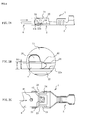
- Fig. 1 is a perspective view of a receptacle terminal of an embodiment of the present invention.
- This receptacle terminal 1 has a cable connection portion 3 that is crimp-connected to a cable, and a contacting portion 2 that is contact-connected to a tab terminal 4.
- the cable connection portion 3 includes a cable fixing part 31 that fixes the cable sheathing, and a core connection part 32 that contacts with and is fixed to the cable core.
- the cable fixing part 31 has a pair of tabs- 31a, 31b, and the cable is fixed by bending and crimping these tabs 31a, 31b.
- the core connection part 32 has a pair of tabs 32a, 32b, and is connected and fixed to the cable core by bending and crimping these tabs 32a, 32b. Further, the bottom has concavities and convexities formed therein. These concavities and convexities are provided to dig into the core during crimp-connection and thereby improve connection to the core.
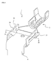
- the contacting portion 2 has a flat part 21 of a flat plate form having a particular area, and a pair of sideplate parts 23, 23 of a particular length that are bent up from the two longitudinal sides of the flat part 21 so as to rise up at perpendicularly.
- the flat part 21 is approximately rectangular in shape, having a width approximately the same as the width of the tab terminal 4, and a particular length such as to contact with the tab terminal 4.
- the flat part 21 has, roughly in the center, a cut-and-lifted piece 22 formed by cutting and lifting a portion thereof. One end of this cut-and-lifted piece 22 is joined to the flat part 21, but the periphery thereof except such joined portion is separated off by a slot 22a.
- the cut-and-lifted piece 22 constitutes a resilient lever possessing elastic force, which is flexed upward and downward with respect to the flat part 21 join portion as the basepoint.
- this elastic force acts as an upward force that lifts the tab terminal 4.
- a small boss 22b that projects from the surface is formed in the cut-and-lifted piece (resilient lever) 22. This small boss fits into a concavity in the tab terminal.
- the pair of sideplate parts 23, 23 both have approximately the same height, and each has a cut-and-lifted-tongue 24, 24 formed therein by cutting and lifting out a portion thereof of a particular size, from the top toward the bottom thereof.
- the sideplate parts 23, 23 are constituted of metal plate of a particular thickness and- possess resilience thanks to having the cut-and-lifted tongues 24, 24 cut and lifted therefrom. For this reason, the cut-and-lifted tongues are termed "spring pieces" below.
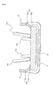
- the spring piece 24 is approximately rectangular in shape, is joined at the upper edge 24a to the upper portion of the sideplate part 23, and has a cut-away slot 25 formed around the periphery, the lower edge 24b being a free extremity (see Fig. 4 ). From near the join with the sideplate part 23, the spring piece 24 is bent toward the other sideplate 23 that opposes that sideplate 23. As Fig. 2B shows, the spring piece 24 is of a length such that a gap G is formed between the free extremity 24b and the flat part 21. The gap G is determined so as to be narrower by ⁇ G than the thickness D of the tab terminal 4.
- the receptacle terminal 1 is formed by punching and bend-processing metal plate. First, a strip-shaped metal plate of good conductivity and having a particular width and length is punched to the size of the outspread receptacle terminal 1. During such punching, the slot 22a and cut-away slot 25 are formed. After such punching, the pair of sideplate parts 23, 23 are formed by bending from the flat part 21 so as to stand up in the same direction. Then the cut-and-lifted piece (resilient lever) 22 and cut-and-lifted tongues (spring pieces) 24, 24 are formed by bending. -Such bendings may alternatively be performed at the time of the punching.
- the receptacle terminal 1 thus manufactured is of a structure such that the tab terminal 4 described hereafter -is supported between the lower sides 24b, 24b of the spring pieces 24, 24 provided in the sideplate parts 23, 23, and the flat part 21.
- the structure that supports the tab terminal 4 is essentially realized by the spring pieces 24, 24 provided in the sideplate parts 23, 23, so that the area of the metal plate of which the receptacle terminal 1 is constituted is rendered small compared with that of the related art. More precisely, it can be rendered small compared with an item of the related art having, for example, the contacting portion formed as a tubular body.
- the spring pieces 24, 24 are formed by cutting and lifting a portion of the sideplate parts 23, 23, the processing is simple.
- the receptacle terminal 1 of this embodiment has low material cost and moreover can be manufactured in a simple manner, enabling the costs to be drastically reduced.
- a single spring piece is provided in each sideplate part, plural ones could alternatively be provided in- each. Providing plural spring pieces would make it possible to vary the spring piece elastic force according to the number of spring pieces, enabling good connection when the tab terminal is inserted.
- the tab terminal 4 is formed from metal plate with good conductivity, and has a contacting part 4a that is inserted into the receptacle terminal 1, and a terminal part 4b that extends from the contacting part 4a and is connected to a lead wire or the like.
- the contacting part 4a is of a width, length and thickness D such as to be inserted between the receptacle terminal 1's pair of sideplate parts 23, 23, and has, formed approximately in the center, a concavity 41 into which the receptacle terminal 1's small boss 22b engages.
- the front end portion of the tab terminal 4 has inclined faces 42 processed in a taper shape.
- Fig. 1 shows the state prior to the tab terminal 4 being inserted into the receptacle terminal 1.
- the tab terminal 4 is slid in the direction indicated by the arrow in Fig. 1 , the front end portion of the tab terminal 4 strikes against the edges of the spring pieces (cut-and-lifted tongues) 24, 24 provided in the sideplate parts of the receptacle terminal 1, as shown in Fig. 2 .
Landscapes
- Coupling Device And Connection With Printed Circuit (AREA)
- Manufacturing Of Electrical Connectors (AREA)
- Multi-Conductor Connections (AREA)
Applications Claiming Priority (1)
| Application Number | Priority Date | Filing Date | Title |
|---|---|---|---|
| SG200705547-8A SG149733A1 (en) | 2007-07-31 | 2007-07-31 | Receptacle terminal |
Publications (2)
| Publication Number | Publication Date |
|---|---|
| EP2020702A2 true EP2020702A2 (de) | 2009-02-04 |
| EP2020702A3 EP2020702A3 (de) | 2009-12-16 |
Family
ID=40010764
Family Applications (1)
| Application Number | Title | Priority Date | Filing Date |
|---|---|---|---|
| EP08252570A Withdrawn EP2020702A3 (de) | 2007-07-31 | 2008-07-29 | Anschlussende |
Country Status (5)
| Country | Link |
|---|---|
| US (1) | US20090036004A1 (de) |
| EP (1) | EP2020702A3 (de) |
| JP (1) | JP2009038012A (de) |
| CN (1) | CN101359787A (de) |
| SG (1) | SG149733A1 (de) |
Cited By (1)
| Publication number | Priority date | Publication date | Assignee | Title |
|---|---|---|---|---|
| WO2014136010A1 (en) * | 2013-03-07 | 2014-09-12 | Tyco Electronics (Shanghai) Co. Ltd. | Connection terminal and connector assembly |
Families Citing this family (8)
| Publication number | Priority date | Publication date | Assignee | Title |
|---|---|---|---|---|
| JP2013168362A (ja) * | 2012-01-20 | 2013-08-29 | Yazaki Corp | 電気コネクタおよびその製造方法 |
| ES2418779B1 (es) * | 2012-02-09 | 2014-09-15 | Orkli, S.Coop. | Conector de un termopar adaptado a una válvula electromagnética de gas y termopar que comprende el conector |
| CN103746206A (zh) * | 2013-12-31 | 2014-04-23 | 温州市珠城电气有限公司 | 旗形夹形自锁端子 |
| US10027037B2 (en) * | 2016-07-06 | 2018-07-17 | Te Connectivity Corporation | Terminal with reduced normal force |
| JP6556787B2 (ja) * | 2017-06-09 | 2019-08-07 | 矢崎総業株式会社 | 端子付き電線および端子圧着装置 |
| CN208111733U (zh) * | 2018-03-13 | 2018-11-16 | 泰科电子(上海)有限公司 | 连接端子 |
| JP2019212458A (ja) * | 2018-06-04 | 2019-12-12 | 矢崎総業株式会社 | 端子付き電線および端子付き電線の製造方法 |
| JP6768742B2 (ja) * | 2018-06-04 | 2020-10-14 | 矢崎総業株式会社 | 端子付き電線および端子付き電線の製造方法 |
Citations (2)
| Publication number | Priority date | Publication date | Assignee | Title |
|---|---|---|---|---|
| US4423921A (en) | 1982-05-17 | 1984-01-03 | Essex Group, Inc. | Tab receptacle terminal |
| US5800220A (en) | 1995-10-23 | 1998-09-01 | Framatome Connectors Interlock Inc. | Tab receptacle terminal |
Family Cites Families (11)
| Publication number | Priority date | Publication date | Assignee | Title |
|---|---|---|---|---|
| US2727219A (en) * | 1951-09-17 | 1955-12-13 | Thomas & Betts Corp | Electric spade terminal receptacle |
| CA653280A (en) * | 1954-12-16 | 1962-12-04 | J. Kinkaid Robert | Terminal clip |
| DE1825172U (de) * | 1960-05-12 | 1961-01-19 | Hans Weber | Flachsteckhuelse, zur verwendung in der elektroindustrie. |
| GB1171678A (en) * | 1967-06-06 | 1969-11-26 | Amp Inc | Electrical connector tab receptacle |
| DE4301949C2 (de) * | 1993-01-25 | 1995-04-13 | Grote & Hartmann | Steckkontaktbuchse für einen Flachsteckstift |
| DE69517671T2 (de) * | 1995-03-09 | 2001-03-01 | Berg Electronics Manufacturing B.V., S'-Hertogenbosch | Verbinderelement zur Verbindung einer flexiblen Folie und eines stiftförmigen Kontaktelements sowie ein dazugehöriges Verbindungswerkzeug und Verfahren zur Herstellung derselben |
| DE29619914U1 (de) * | 1996-11-18 | 1997-01-09 | Stocko Metallwarenfabriken Henkels & Sohn GmbH & Co, 42327 Wuppertal | Flachsteckhülse für eine elektrische Verbindung |
| DE19835020C2 (de) * | 1998-08-03 | 2001-02-08 | Tyco Electronics Logistics Ag | Buchsenkontakt |
| GB0016790D0 (en) * | 2000-07-07 | 2000-08-30 | Tyco Electronics Amp Es Sa | Electrical connector |
| JP2005353524A (ja) * | 2004-06-14 | 2005-12-22 | Yazaki Corp | 接続端子 |
| US7422494B2 (en) * | 2006-09-29 | 2008-09-09 | Tyco Electronics Corporation | Two-piece electrical terminal |
-
2007
- 2007-07-31 SG SG200705547-8A patent/SG149733A1/en unknown
-
2008
- 2008-06-23 JP JP2008163518A patent/JP2009038012A/ja active Pending
- 2008-07-23 US US12/219,492 patent/US20090036004A1/en not_active Abandoned
- 2008-07-29 EP EP08252570A patent/EP2020702A3/de not_active Withdrawn
- 2008-07-31 CN CNA2008101451205A patent/CN101359787A/zh active Pending
Patent Citations (2)
| Publication number | Priority date | Publication date | Assignee | Title |
|---|---|---|---|---|
| US4423921A (en) | 1982-05-17 | 1984-01-03 | Essex Group, Inc. | Tab receptacle terminal |
| US5800220A (en) | 1995-10-23 | 1998-09-01 | Framatome Connectors Interlock Inc. | Tab receptacle terminal |
Cited By (1)
| Publication number | Priority date | Publication date | Assignee | Title |
|---|---|---|---|---|
| WO2014136010A1 (en) * | 2013-03-07 | 2014-09-12 | Tyco Electronics (Shanghai) Co. Ltd. | Connection terminal and connector assembly |
Also Published As
| Publication number | Publication date |
|---|---|
| SG149733A1 (en) | 2009-02-27 |
| CN101359787A (zh) | 2009-02-04 |
| JP2009038012A (ja) | 2009-02-19 |
| EP2020702A3 (de) | 2009-12-16 |
| US20090036004A1 (en) | 2009-02-05 |
Similar Documents
| Publication | Publication Date | Title |
|---|---|---|
| EP2020702A2 (de) | Anschlussende | |
| US7344422B2 (en) | Electrical component, in particular relay socket, having spring clamps, and method for the manufacture thereof | |
| CN1653650B (zh) | 连接端子 | |
| CN107086396B (zh) | 母端子和母端子的制造方法 | |
| CN100466387C (zh) | 扁平电缆用电气接头 | |
| US9601854B2 (en) | Female terminal | |
| US5885090A (en) | Electrical connector with stabilized offset spring arm | |
| JP2012069243A (ja) | 電気接続用端子及びこれを用いたコネクタ | |
| US8298010B2 (en) | Connector | |
| JPH07296873A (ja) | 雌型コンタクト | |
| US10056714B2 (en) | Connector device including coming-off preventing structure | |
| JPH07326416A (ja) | 端子及びコネクタ | |
| US6764357B2 (en) | Electrical connector and method of assembling the same | |
| US20060128204A1 (en) | Electric connector | |
| EP1742300A1 (de) | Anschlusskontakt und Herstellungsverfahren dafür | |
| US20070010110A1 (en) | Electric connector and method for manufacturing the same | |
| EP1057227A1 (de) | Elektrisches anschlusselement mit käfig | |
| EP2183822B1 (de) | Elektrischer kontakt | |
| CN117039545A (zh) | 连接器、屏蔽片、接地接触件及插孔的成型方法 | |
| JP6651393B2 (ja) | 圧接コンタクト及び圧接コネクタ | |
| CN110649398A (zh) | 电缆与端子的连接结构 | |
| JP7106090B2 (ja) | 電気コネクタ | |
| CN106981752B (zh) | 用于母连接器的电端子及其制造方法 | |
| JPH05335044A (ja) | 雌型端子の接触構造 | |
| JP2002190330A (ja) | 圧接端子金具及びその製造方法 |
Legal Events
| Date | Code | Title | Description |
|---|---|---|---|
| PUAI | Public reference made under article 153(3) epc to a published international application that has entered the european phase |
Free format text: ORIGINAL CODE: 0009012 |
|
| AK | Designated contracting states |
Kind code of ref document: A2 Designated state(s): AT BE BG CH CY CZ DE DK EE ES FI FR GB GR HR HU IE IS IT LI LT LU LV MC MT NL NO PL PT RO SE SI SK TR |
|
| AX | Request for extension of the european patent |
Extension state: AL BA MK RS |
|
| 17P | Request for examination filed |
Effective date: 20090302 |
|
| PUAL | Search report despatched |
Free format text: ORIGINAL CODE: 0009013 |
|
| AK | Designated contracting states |
Kind code of ref document: A3 Designated state(s): AT BE BG CH CY CZ DE DK EE ES FI FR GB GR HR HU IE IS IT LI LT LU LV MC MT NL NO PL PT RO SE SI SK TR |
|
| AX | Request for extension of the european patent |
Extension state: AL BA MK RS |
|
| 17Q | First examination report despatched |
Effective date: 20100628 |
|
| AKX | Designation fees paid |
Designated state(s): DE FR GB |
|
| STAA | Information on the status of an ep patent application or granted ep patent |
Free format text: STATUS: THE APPLICATION IS DEEMED TO BE WITHDRAWN |
|
| 18D | Application deemed to be withdrawn |
Effective date: 20101109 |