EP2020366B1 - Dachspoileranordnung für Nutzfahrzeug-Fahrerhäuser - Google Patents
Dachspoileranordnung für Nutzfahrzeug-Fahrerhäuser Download PDFInfo
- Publication number
- EP2020366B1 EP2020366B1 EP08012205A EP08012205A EP2020366B1 EP 2020366 B1 EP2020366 B1 EP 2020366B1 EP 08012205 A EP08012205 A EP 08012205A EP 08012205 A EP08012205 A EP 08012205A EP 2020366 B1 EP2020366 B1 EP 2020366B1
- Authority
- EP
- European Patent Office
- Prior art keywords
- roof
- spoiler
- sliding guide
- array
- guide part
- Prior art date
- Legal status (The legal status is an assumption and is not a legal conclusion. Google has not performed a legal analysis and makes no representation as to the accuracy of the status listed.)
- Active
Links
Images

Classifications
-
- B—PERFORMING OPERATIONS; TRANSPORTING
- B62—LAND VEHICLES FOR TRAVELLING OTHERWISE THAN ON RAILS
- B62D—MOTOR VEHICLES; TRAILERS
- B62D35/00—Vehicle bodies characterised by streamlining
- B62D35/001—For commercial vehicles or tractor-trailer combinations, e.g. caravans
Definitions
- the invention relates to a roof spoiler arrangement for commercial vehicle cabs according to the preamble of claim 1.
- roof spoiler it is well known to equip utility vehicles, especially long-haul trucks, with a roof spoiler to improve the aerodynamics of the vehicle.
- roof spoiler In order to be able to further compensate for the difference in height of the driver's cab or the driver's cab, to compensate fixed or movable, higher or wider superstructures or semi-trailers, it is necessary for the roof spoiler itself to be designed to be adjustable in height.
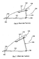
- FIGS. 6 and 7 represent the prior art generally known to provide a roof spoiler assembly for commercial vehicle cabs, in which a roof spoiler 100 is pivotable about a spoiler axis 103 as a rotation axis by means of a provided on the roof 101 of a cab pivot bearing assembly 102.
- a roof spoiler 100 is pivotable about a spoiler axis 103 as a rotation axis by means of a provided on the roof 101 of a cab pivot bearing assembly 102.
- Next is a spaced from the pivot bearing assembly arranged in the vehicle longitudinal direction behind adjusting 104, by means of the roof spoiler 100, as the FIGS. 6 and 7 it can be seen in different pivot position transferred and preserved there.
- the adjustment here consists of a strut joint arrangement with a first roof-side hinged strut 105, which is articulated via a pivot bearing 106 hinged to the roof, and a second strut 107, which is connected via a pivot bearing 108 hingedly connected to the first strut 105.
- These two pivot bearings 106, 108 are required in conjunction with the pivot bearing assembly 102 to facilitate easy and convenient pivotal movement of the roof spoiler 100 between the various pivot positions.
- two strut joint arrangements spaced apart from each other between the rear free roof spoiler end and the roof 101 are provided here (not shown) in the vehicle transverse direction.
- the first strut 105 is also designed as a telescopic strut, via which the adjustment is given.
- Such a structure has a certain reliability, but is technically complex component.
- a roof spoiler assembly for commercial vehicle cabs is already known in which a wind deflector designated roof spoiler is fastened by means of two front bearing on a roof of a cab.
- a carrying device is arranged on this, which is formed by a cross tube to which in turn centrally a support arm is attached.
- the support arm extends in the assembled state down and can be connected to a support which is fixedly arranged on the vehicle roof. This support is arranged as seen in the direction of travel behind the support arm and thus forms the outer part of the support device.
- a bracket is provided for height adjustment on the support arm, on which a shoe is attached.
- this shoe there is a threaded recess.
- This thread recess receives a screw with a washer on a bracket, so that the support between the bracket and the shoe can be arranged.
- the shoe surface is applicable to a curved surface of the support, wherein the curved surface is part of a cylindrical surface about the axis of rotation of the hinge device.
- the clamp is located on a convex surface of the support, which is parallel to the curved surface and centrally has a slot. At the end portions, the bracket has teeth that engage vertical teeth portions.
- the screw is released, the sliding shoe on the curved surface, the bracket on the convex surface and finally the screw in the slot moved to then at the desired height, the engaging portions (teeth) by engaging the screw with the then correspondingly associated tooth portions of the support into engagement.
- Such a structure is generally a relatively complex component and also has the risk that the screw may loosen during rough driving operation and thus can no longer reliably hold the safe, desired height fixation of the roof spoiler in position. In addition, there is the danger here that in case of loss of the screw and the clip is lost and thus without a corresponding Replacing this clamp no working roof spoiler is available anymore. Overall, it is therefore in such a structure to a less viable solution.
- GB 2 393 694 A a structure in which a roof spoiler with a leg surrounds a spoiler-side vertical element from the outside.
- the fixation takes place here via associated and aligned screw holes, through which a fastening screw is screwed through.
- the spoiler-side sliding guide member surrounds the roof-side sliding guide member in the vehicle longitudinal direction in the direction away from the spoiler axis seen from the outside, wherein the spoiler-side and the roof-side sliding guide part at their facing sides of the plant holding means by which the sliding guide parts are stable in their set position, said the holding means are formed by an overpressable connection with each other along the displacement path assignable locking elements and locking counter-elements.
- such a structure can be produced and implemented in a particularly simple and inexpensive manner with few components and, moreover, there is no danger of components possibly loosening during rough driving and thus leading to the loss of these components, which in turn leads to damage or a loss of function of the components Height adjustment and thus the roof spoiler assembly leads overall.
- a particularly functionally reliable pivoting of the roof spoiler which is easy to control in terms of component technology, is also possible, preferably around a spoiler axis formed by a pivot bearing arrangement, as the pivot axis.
- the use of a variety of component-intensive spherical bearings for the realization of the pivotal adjustment of the roof spoiler can thus be advantageously eliminated, so that according to the preferred embodiment only a single pivot bearing assembly for forming the spoiler axle needs to be provided, but not for the height adjustment of the roof spoiler.
- a particular advantage of such sliding guide is the fact that can be provided by the supporting abutment connection of the two sliding guide parts in a simple way a very reliable, less prone to interference, stable formable and easy-to-use adjustment.
- the supporting system connection of such a sliding guide causes namely a guided relative displacement of the two sliding guide parts to each other, which ensures the reliable and reliable pivoting of the roof spoiler.
- in conjunction with a according to a preferred embodiment arrangement of two such sliding guides on seen in the vehicle transverse direction in approximately opposite Dachspoilereckrand Schemeen thus a reliable, exactly synchronizedfeaturenverschwenkung the roof spoiler without additional connecting strut between the two sliding guide bearings achieve, as in the strut joint arrangement according to the previously appreciated prior art is required.
- the component diversity can be particularly reduced as such, so that the adjusting device according to the invention in the form of a sliding guide also easier to assemble and thus is less expensive to manufacture.
- the use of a plurality of spaced apart in the vehicle transverse direction and preferably in the vehicle longitudinal direction in each case an equal distance from the spoiler axle having sliding guides is a preferred embodiment, as a functionally reliable support of the roof spoiler in the predetermined pivoting position is possible.
- a functionally reliable support of the roof spoiler in the predetermined pivoting position is possible.
- a supporting frame system for a roof spoiler is provided with the roof spoiler assembly according to the invention, which allows a structurally simple manner with high reliability pivoting of the roof spoiler in different pivot positions.
- the spoiler-side and the roof-side sliding guide part lie flat against one another with their respective contact sides in each case. This provides a stable support of the sliding guide parts both in their rest position and during pivoting available.
- the latching structure is formed so that in the latched state latching elements in the form of latching elements engage in a form-fitting manner in the latching counter-elements formed in the form of latching grooves.
- a latching structure is simple, z. B. produced by stampings or the like.
- such a latching structure is very good überdrückbar especially in a more wavy configuration with a corresponding application of force.
- a very good and reliable control is possible on such locking structures, whether in the case of several sliding guides these each have a same height adjustment of the two sliding guide parts to each other. If appropriate, this can be optically supported by additional markings or corresponding shaping of individual latching structure areas.
- additional fasteners may optionally be provided, for. B. additional mounting screws or securing split or the like.
- the spoiler-side sliding guide member and the roof-side sliding guide member are each formed L-shaped such that in each case a first L-leg is firmly connected to the roof spoiler or the roof, while the respective second L-legs in the supporting abutment relative to each other displaceable abut each other ,
- Such a structure is component technology relatively easy to produce and in particular also allows easy installation in a series production.
- such sliding guide parts can basically be made of a low-cost plastic material.
- the roof-side sliding guide part is arranged on the rear roof edge region of a roof viewed in the vehicle longitudinal direction.
- This roof can be any type of roof, so be a normal roof, a flat roof or a high roof of a cab.
- the pivot bearing arrangement itself which is preferably formed by two hinges spaced apart from one another in the vehicle transverse direction, can additionally also have bearing blocks via which an advantageous and functionally reliable attachment of the hinges to the roof of the driver's cab can take place.
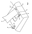
- the Fig. 1 shows schematically and in perspective a plan view of a high roof 1, which is part of a driver's cab or a driver's cab, not shown here.
- This roof 1 has, in a central region, a pivot bearing arrangement 4 formed by two hinges 2, 3 spaced apart in the vehicle transverse direction y, by means of which a roof spoiler 5 is pivotably connected to the high roof 1.
- the two hinges 2, 3 of the pivot bearing assembly 4 are mounted on bearing blocks 6, 7, which are shown here only extremely schematically, on the high roof 1 and form a spoiler axis 8 as a pivot axis for the roof spoiler 5.
- this sliding guide 9 is composed of a roof-side sliding guide member 10 and a spoiler-side sliding guide member 11, respectively.
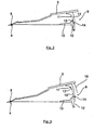
- the roof-side sliding guide member 10 also has as the spoiler-side sliding guide member 11 has an L-shape. Both the roof-side sliding guide member 10 and the spoiler-side sliding guide member 11 are z. B. screwed to the roof 1 and the roof spoiler 5 firmly, in such a way that the two free L-legs 12, 13 abut with their mutually facing abutment surfaces in an abutment surface to each other, as in particular the FIGS. 2 and 3 can be seen.
- the spoiler-side sliding guide part 11 surrounds the roof-side sliding guide part 10 from behind and thus from the outside.
- the contact surfaces forming the contact surfaces 14, 15 have a circular arc geometry corresponding to a circular arc around the spoiler axis 8 as the center of the circle, so that at one in the Fig. 3 schematically shown pivoting adjustment of the roof spoiler 5 in the direction of arrow 16, the spoiler-side sliding guide member is displaced relative to the stationary roof-side sliding guide member 10 such that the roof spoiler 5 is pivoted upwards by a predetermined pivoting angle.
- the spoiler-side sliding guide member 11 slides with its L-leg 13 by means of its contact surface 15 by the predetermined displacement along the contact surface 14 of the L-leg 12 of the roof-side sliding guide part 10 and supported upward, wherein by the circular arc geometry, as described above has been ensured that a functionally safe succession-slipping of the two contact surfaces 14, 15 can be done without jamming or spreading.
- the two contact surfaces 14, 15 a latching structure 17 which is formed here by latching lugs 18 and locking grooves 19, wherein the latching lugs 18 are formed so that they engage positively and überdrückbar in the locking grooves 19.
- a reliable and secure positioning of the roof spoiler 5 in a desired pivoting position is possible, in particular a holding of the roof spoiler 5 in a desired pivoting position.
- a once taken detent position also not shown here with additional fixatives, z. B. a split pin or the like, are additionally fixed.
- z. B. in conjunction with the locking lugs 18 and / or locking grooves 19 additional markings may be provided which allow for a plurality of vehicle transverse direction y spaced sliding guides 9 a simple assignment of the respective locking lugs 18 and locking grooves 19 at a same height. This is also not shown here, for example, such markings can, however, by z. As numbers or the like can be specified.
Landscapes
- Engineering & Computer Science (AREA)
- Chemical & Material Sciences (AREA)
- Combustion & Propulsion (AREA)
- Transportation (AREA)
- Mechanical Engineering (AREA)
- Fittings On The Vehicle Exterior For Carrying Loads, And Devices For Holding Or Mounting Articles (AREA)
- Body Structure For Vehicles (AREA)
- Lighting Device Outwards From Vehicle And Optical Signal (AREA)
Priority Applications (1)
| Application Number | Priority Date | Filing Date | Title |
|---|---|---|---|
| PL08012205T PL2020366T3 (pl) | 2007-08-02 | 2008-07-07 | Układ spojlera dachowego do kabin kierowców w pojazdach użytkowych |
Applications Claiming Priority (1)
| Application Number | Priority Date | Filing Date | Title |
|---|---|---|---|
| DE102007036335A DE102007036335A1 (de) | 2007-08-02 | 2007-08-02 | Dachspoileranordnung für Nutzfahrzeug-Fahrerhäuser |
Publications (3)
| Publication Number | Publication Date |
|---|---|
| EP2020366A2 EP2020366A2 (de) | 2009-02-04 |
| EP2020366A3 EP2020366A3 (de) | 2009-04-08 |
| EP2020366B1 true EP2020366B1 (de) | 2010-04-07 |
Family
ID=40020221
Family Applications (1)
| Application Number | Title | Priority Date | Filing Date |
|---|---|---|---|
| EP08012205A Active EP2020366B1 (de) | 2007-08-02 | 2008-07-07 | Dachspoileranordnung für Nutzfahrzeug-Fahrerhäuser |
Country Status (4)
| Country | Link |
|---|---|
| EP (1) | EP2020366B1 (pl) |
| AT (1) | ATE463411T1 (pl) |
| DE (2) | DE102007036335A1 (pl) |
| PL (1) | PL2020366T3 (pl) |
Cited By (1)
| Publication number | Priority date | Publication date | Assignee | Title |
|---|---|---|---|---|
| DE102019007558A1 (de) * | 2019-10-30 | 2021-05-06 | Man Truck & Bus Se | Baukastensystem und Verbindungseinrichtung für Kraftfahrzeug-Luftleitelemente |
Families Citing this family (5)
| Publication number | Priority date | Publication date | Assignee | Title |
|---|---|---|---|---|
| DE102019008489A1 (de) | 2019-12-06 | 2021-06-10 | Man Truck & Bus Se | Kraftfahrzeug mit Dachspoiler |
| DE102019008488B4 (de) * | 2019-12-06 | 2026-03-19 | Man Truck & Bus Se | Kraftfahrzeug mit Scheibenreinigungsanlage |
| DE102022123922A1 (de) | 2022-09-19 | 2024-03-21 | Quantron Ag | Spoileranordnung für ein fahrzeug und fahrzeug mit einer solchen spoileranordnung |
| CN115973291B (zh) * | 2022-11-25 | 2025-06-24 | 东风汽车集团股份有限公司 | 一种尾翼及车辆 |
| DE102023111074A1 (de) | 2023-04-28 | 2024-10-31 | Quantron Ag | Spoilervorrichtung, Spoileranordnung, Fahrzeug sowie Verwendung |
Family Cites Families (4)
| Publication number | Priority date | Publication date | Assignee | Title |
|---|---|---|---|---|
| US4082340A (en) * | 1976-08-03 | 1978-04-04 | Alexander Taylor | Air current deflecting device |
| DE19825252A1 (de) * | 1998-06-05 | 1999-12-09 | Fritzmeier Composite Gmbh & Co | Windabweiser |
| AT407628B (de) * | 1999-04-08 | 2001-05-25 | Steyr Nutzfahrzeuge | Halterung für einen am fahrerhausdach eines lastkraftwagens angeordneten dachspoiler |
| GB0222735D0 (en) * | 2002-10-01 | 2002-11-06 | Bacon Andy | Aerodynamic fairing |
-
2007
- 2007-08-02 DE DE102007036335A patent/DE102007036335A1/de not_active Withdrawn
-
2008
- 2008-07-07 DE DE502008000518T patent/DE502008000518D1/de active Active
- 2008-07-07 PL PL08012205T patent/PL2020366T3/pl unknown
- 2008-07-07 AT AT08012205T patent/ATE463411T1/de active
- 2008-07-07 EP EP08012205A patent/EP2020366B1/de active Active
Cited By (2)
| Publication number | Priority date | Publication date | Assignee | Title |
|---|---|---|---|---|
| DE102019007558A1 (de) * | 2019-10-30 | 2021-05-06 | Man Truck & Bus Se | Baukastensystem und Verbindungseinrichtung für Kraftfahrzeug-Luftleitelemente |
| WO2021083708A1 (de) | 2019-10-30 | 2021-05-06 | Man Truck & Bus Se | Baukastensystem und verbindungseinrichtung für kraftfahrzeug-luftleitelemente |
Also Published As
| Publication number | Publication date |
|---|---|
| DE502008000518D1 (de) | 2010-05-20 |
| DE102007036335A1 (de) | 2009-03-05 |
| EP2020366A2 (de) | 2009-02-04 |
| ATE463411T1 (de) | 2010-04-15 |
| PL2020366T3 (pl) | 2010-09-30 |
| EP2020366A3 (de) | 2009-04-08 |
Similar Documents
| Publication | Publication Date | Title |
|---|---|---|
| DE4345523C2 (de) | Überrollschutzsystem | |
| EP2817195B1 (de) | Lenksäule für ein kraftfahrzeug mit einem tragteil | |
| EP2020366B1 (de) | Dachspoileranordnung für Nutzfahrzeug-Fahrerhäuser | |
| DE102008047249A1 (de) | Rückenlehnenstruktur für einen Kraftfahrzeugsitz | |
| EP1878622B1 (de) | Befestigungsvorrichtung für ein Anbauteil eines Kraftfahrzeugs | |
| EP1884410A2 (de) | Hecklastenträger | |
| DE2430003A1 (de) | Universelle halterungsanordnung fuer einen windschutz | |
| EP3755602A1 (de) | Lenksäule für ein kraftfahrzeug | |
| DE102011088852B4 (de) | Luftleitvorrichtung für ein Fahrzeug | |
| EP2776248A2 (de) | Siebdruckrakel und vorrichtung zum siebdrucken | |
| DE2551335A1 (de) | Schiebedach fuer kraftfahrzeuge | |
| DE10250905B4 (de) | Verstelleinrichtung für ein Lenkrad eines Flurförderzeugs | |
| DE102015201365A1 (de) | Unterfahrschutzeinrichtung | |
| EP3183133B1 (de) | Gleiter zum führen eines verlagerbaren elements | |
| EP3456591A1 (de) | Bauteilsystem zur fixierung eines verkleidungsteils und kraftfahrzeug | |
| EP2216205B1 (de) | Dachlastenträger für Kraftfahrzeuge | |
| DE102007024570B4 (de) | Scharnier für eine Kraftfahrzeugtür | |
| EP0328867B1 (de) | Sonnenblende für Fahrzeuge | |
| DE102023110302A1 (de) | Kraftfahrzeugkarosserie eines Kraftfahrzeugs | |
| EP3825175B1 (de) | Fahrzeugsitz | |
| EP0327728A1 (de) | Stossfangvorrichtung für Kraftfahrzeuge | |
| DE102011056729A1 (de) | Windabweiseranordnung für ein Fahrzeug sowie Kraftfahrzeug mit einer solchen Windabweiseranordnung | |
| DE102021129860A1 (de) | Fahrzeugsitz für einen Kraftwagen mit einer Deformationseinrichtung | |
| DE102004058991A1 (de) | Luftleitvorrichtung für ein Cabriolet-Fahrzeug | |
| DE10320820B4 (de) | Schwenklagereinrichtung für ein verstellbares Bauteil sowie Verfahren zur Montage einer solchen Schwenklagereinrichtung |
Legal Events
| Date | Code | Title | Description |
|---|---|---|---|
| PUAI | Public reference made under article 153(3) epc to a published international application that has entered the european phase |
Free format text: ORIGINAL CODE: 0009012 |
|
| AK | Designated contracting states |
Kind code of ref document: A2 Designated state(s): AT BE BG CH CY CZ DE DK EE ES FI FR GB GR HR HU IE IS IT LI LT LU LV MC MT NL NO PL PT RO SE SI SK TR |
|
| AX | Request for extension of the european patent |
Extension state: AL BA MK RS |
|
| PUAL | Search report despatched |
Free format text: ORIGINAL CODE: 0009013 |
|
| AK | Designated contracting states |
Kind code of ref document: A3 Designated state(s): AT BE BG CH CY CZ DE DK EE ES FI FR GB GR HR HU IE IS IT LI LT LU LV MC MT NL NO PL PT RO SE SI SK TR |
|
| AX | Request for extension of the european patent |
Extension state: AL BA MK RS |
|
| 17P | Request for examination filed |
Effective date: 20090424 |
|
| 17Q | First examination report despatched |
Effective date: 20090605 |
|
| AKX | Designation fees paid |
Designated state(s): AT BE BG CH CY CZ DE DK EE ES FI FR GB GR HR HU IE IS IT LI LT LU LV MC MT NL NO PL PT RO SE SI SK TR |
|
| GRAP | Despatch of communication of intention to grant a patent |
Free format text: ORIGINAL CODE: EPIDOSNIGR1 |
|
| GRAS | Grant fee paid |
Free format text: ORIGINAL CODE: EPIDOSNIGR3 |
|
| GRAA | (expected) grant |
Free format text: ORIGINAL CODE: 0009210 |
|
| AK | Designated contracting states |
Kind code of ref document: B1 Designated state(s): AT BE BG CH CY CZ DE DK EE ES FI FR GB GR HR HU IE IS IT LI LT LU LV MC MT NL NO PL PT RO SE SI SK TR |
|
| REG | Reference to a national code |
Ref country code: GB Ref legal event code: FG4D Free format text: NOT ENGLISH |
|
| REG | Reference to a national code |
Ref country code: CH Ref legal event code: EP |
|
| REG | Reference to a national code |
Ref country code: NL Ref legal event code: T3 |
|
| REG | Reference to a national code |
Ref country code: IE Ref legal event code: FG4D Free format text: LANGUAGE OF EP DOCUMENT: GERMAN |
|
| REF | Corresponds to: |
Ref document number: 502008000518 Country of ref document: DE Date of ref document: 20100520 Kind code of ref document: P |
|
| REG | Reference to a national code |
Ref country code: SE Ref legal event code: TRGR |
|
| PG25 | Lapsed in a contracting state [announced via postgrant information from national office to epo] |
Ref country code: SI Free format text: LAPSE BECAUSE OF FAILURE TO SUBMIT A TRANSLATION OF THE DESCRIPTION OR TO PAY THE FEE WITHIN THE PRESCRIBED TIME-LIMIT Effective date: 20100407 |
|
| LTIE | Lt: invalidation of european patent or patent extension |
Effective date: 20100407 |
|
| REG | Reference to a national code |
Ref country code: PL Ref legal event code: T3 |
|
| REG | Reference to a national code |
Ref country code: IE Ref legal event code: FD4D |
|
| PG25 | Lapsed in a contracting state [announced via postgrant information from national office to epo] |
Ref country code: NO Free format text: LAPSE BECAUSE OF FAILURE TO SUBMIT A TRANSLATION OF THE DESCRIPTION OR TO PAY THE FEE WITHIN THE PRESCRIBED TIME-LIMIT Effective date: 20100707 Ref country code: LT Free format text: LAPSE BECAUSE OF FAILURE TO SUBMIT A TRANSLATION OF THE DESCRIPTION OR TO PAY THE FEE WITHIN THE PRESCRIBED TIME-LIMIT Effective date: 20100407 Ref country code: ES Free format text: LAPSE BECAUSE OF FAILURE TO SUBMIT A TRANSLATION OF THE DESCRIPTION OR TO PAY THE FEE WITHIN THE PRESCRIBED TIME-LIMIT Effective date: 20100718 |
|
| PG25 | Lapsed in a contracting state [announced via postgrant information from national office to epo] |
Ref country code: HR Free format text: LAPSE BECAUSE OF FAILURE TO SUBMIT A TRANSLATION OF THE DESCRIPTION OR TO PAY THE FEE WITHIN THE PRESCRIBED TIME-LIMIT Effective date: 20100407 Ref country code: FI Free format text: LAPSE BECAUSE OF FAILURE TO SUBMIT A TRANSLATION OF THE DESCRIPTION OR TO PAY THE FEE WITHIN THE PRESCRIBED TIME-LIMIT Effective date: 20100407 Ref country code: LV Free format text: LAPSE BECAUSE OF FAILURE TO SUBMIT A TRANSLATION OF THE DESCRIPTION OR TO PAY THE FEE WITHIN THE PRESCRIBED TIME-LIMIT Effective date: 20100407 Ref country code: IS Free format text: LAPSE BECAUSE OF FAILURE TO SUBMIT A TRANSLATION OF THE DESCRIPTION OR TO PAY THE FEE WITHIN THE PRESCRIBED TIME-LIMIT Effective date: 20100807 |
|
| PG25 | Lapsed in a contracting state [announced via postgrant information from national office to epo] |
Ref country code: CY Free format text: LAPSE BECAUSE OF FAILURE TO SUBMIT A TRANSLATION OF THE DESCRIPTION OR TO PAY THE FEE WITHIN THE PRESCRIBED TIME-LIMIT Effective date: 20100609 |
|
| BERE | Be: lapsed |
Owner name: MAN NUTZFAHRZEUGE A.G. Effective date: 20100731 |
|
| PG25 | Lapsed in a contracting state [announced via postgrant information from national office to epo] |
Ref country code: DK Free format text: LAPSE BECAUSE OF FAILURE TO SUBMIT A TRANSLATION OF THE DESCRIPTION OR TO PAY THE FEE WITHIN THE PRESCRIBED TIME-LIMIT Effective date: 20100407 Ref country code: EE Free format text: LAPSE BECAUSE OF FAILURE TO SUBMIT A TRANSLATION OF THE DESCRIPTION OR TO PAY THE FEE WITHIN THE PRESCRIBED TIME-LIMIT Effective date: 20100407 Ref country code: IE Free format text: LAPSE BECAUSE OF FAILURE TO SUBMIT A TRANSLATION OF THE DESCRIPTION OR TO PAY THE FEE WITHIN THE PRESCRIBED TIME-LIMIT Effective date: 20100407 |
|
| PLBE | No opposition filed within time limit |
Free format text: ORIGINAL CODE: 0009261 |
|
| STAA | Information on the status of an ep patent application or granted ep patent |
Free format text: STATUS: NO OPPOSITION FILED WITHIN TIME LIMIT |
|
| PG25 | Lapsed in a contracting state [announced via postgrant information from national office to epo] |
Ref country code: CZ Free format text: LAPSE BECAUSE OF FAILURE TO SUBMIT A TRANSLATION OF THE DESCRIPTION OR TO PAY THE FEE WITHIN THE PRESCRIBED TIME-LIMIT Effective date: 20100407 Ref country code: MC Free format text: LAPSE BECAUSE OF NON-PAYMENT OF DUE FEES Effective date: 20100731 Ref country code: SK Free format text: LAPSE BECAUSE OF FAILURE TO SUBMIT A TRANSLATION OF THE DESCRIPTION OR TO PAY THE FEE WITHIN THE PRESCRIBED TIME-LIMIT Effective date: 20100407 Ref country code: RO Free format text: LAPSE BECAUSE OF FAILURE TO SUBMIT A TRANSLATION OF THE DESCRIPTION OR TO PAY THE FEE WITHIN THE PRESCRIBED TIME-LIMIT Effective date: 20100407 |
|
| 26N | No opposition filed |
Effective date: 20110110 |
|
| REG | Reference to a national code |
Ref country code: NL Ref legal event code: TD Effective date: 20110420 |
|
| REG | Reference to a national code |
Ref country code: FR Ref legal event code: CD |
|
| PG25 | Lapsed in a contracting state [announced via postgrant information from national office to epo] |
Ref country code: GR Free format text: LAPSE BECAUSE OF FAILURE TO SUBMIT A TRANSLATION OF THE DESCRIPTION OR TO PAY THE FEE WITHIN THE PRESCRIBED TIME-LIMIT Effective date: 20100708 |
|
| PG25 | Lapsed in a contracting state [announced via postgrant information from national office to epo] |
Ref country code: BE Free format text: LAPSE BECAUSE OF NON-PAYMENT OF DUE FEES Effective date: 20100731 |
|
| REG | Reference to a national code |
Ref country code: DE Ref legal event code: R081 Ref document number: 502008000518 Country of ref document: DE Owner name: MAN TRUCK & BUS AG, DE Free format text: FORMER OWNER: MAN NUTZFAHRZEUGE AG, 80995 MUENCHEN, DE Effective date: 20110518 |
|
| PG25 | Lapsed in a contracting state [announced via postgrant information from national office to epo] |
Ref country code: MT Free format text: LAPSE BECAUSE OF FAILURE TO SUBMIT A TRANSLATION OF THE DESCRIPTION OR TO PAY THE FEE WITHIN THE PRESCRIBED TIME-LIMIT Effective date: 20100407 |
|
| PG25 | Lapsed in a contracting state [announced via postgrant information from national office to epo] |
Ref country code: LU Free format text: LAPSE BECAUSE OF NON-PAYMENT OF DUE FEES Effective date: 20100707 Ref country code: BG Free format text: LAPSE BECAUSE OF FAILURE TO SUBMIT A TRANSLATION OF THE DESCRIPTION OR TO PAY THE FEE WITHIN THE PRESCRIBED TIME-LIMIT Effective date: 20100407 Ref country code: HU Free format text: LAPSE BECAUSE OF FAILURE TO SUBMIT A TRANSLATION OF THE DESCRIPTION OR TO PAY THE FEE WITHIN THE PRESCRIBED TIME-LIMIT Effective date: 20101008 Ref country code: PT Free format text: LAPSE BECAUSE OF FAILURE TO SUBMIT A TRANSLATION OF THE DESCRIPTION OR TO PAY THE FEE WITHIN THE PRESCRIBED TIME-LIMIT Effective date: 20100907 |
|
| PG25 | Lapsed in a contracting state [announced via postgrant information from national office to epo] |
Ref country code: TR Free format text: LAPSE BECAUSE OF FAILURE TO SUBMIT A TRANSLATION OF THE DESCRIPTION OR TO PAY THE FEE WITHIN THE PRESCRIBED TIME-LIMIT Effective date: 20100407 |
|
| REG | Reference to a national code |
Ref country code: CH Ref legal event code: PL |
|
| GBPC | Gb: european patent ceased through non-payment of renewal fee |
Effective date: 20120707 |
|
| PG25 | Lapsed in a contracting state [announced via postgrant information from national office to epo] |
Ref country code: CH Free format text: LAPSE BECAUSE OF NON-PAYMENT OF DUE FEES Effective date: 20120731 Ref country code: LI Free format text: LAPSE BECAUSE OF NON-PAYMENT OF DUE FEES Effective date: 20120731 Ref country code: GB Free format text: LAPSE BECAUSE OF NON-PAYMENT OF DUE FEES Effective date: 20120707 |
|
| PG25 | Lapsed in a contracting state [announced via postgrant information from national office to epo] |
Ref country code: BG Free format text: LAPSE BECAUSE OF FAILURE TO SUBMIT A TRANSLATION OF THE DESCRIPTION OR TO PAY THE FEE WITHIN THE PRESCRIBED TIME-LIMIT Effective date: 20100707 |
|
| REG | Reference to a national code |
Ref country code: FR Ref legal event code: PLFP Year of fee payment: 9 |
|
| REG | Reference to a national code |
Ref country code: FR Ref legal event code: PLFP Year of fee payment: 10 |
|
| REG | Reference to a national code |
Ref country code: FR Ref legal event code: PLFP Year of fee payment: 11 |
|
| REG | Reference to a national code |
Ref country code: DE Ref legal event code: R081 Ref document number: 502008000518 Country of ref document: DE Owner name: MAN TRUCK & BUS SE, DE Free format text: FORMER OWNER: MAN TRUCK & BUS AG, 80995 MUENCHEN, DE |
|
| PGFP | Annual fee paid to national office [announced via postgrant information from national office to epo] |
Ref country code: PL Payment date: 20250626 Year of fee payment: 18 |
|
| PGFP | Annual fee paid to national office [announced via postgrant information from national office to epo] |
Ref country code: NL Payment date: 20250724 Year of fee payment: 18 |
|
| PGFP | Annual fee paid to national office [announced via postgrant information from national office to epo] |
Ref country code: DE Payment date: 20250728 Year of fee payment: 18 |
|
| PGFP | Annual fee paid to national office [announced via postgrant information from national office to epo] |
Ref country code: IT Payment date: 20250721 Year of fee payment: 18 |
|
| PGFP | Annual fee paid to national office [announced via postgrant information from national office to epo] |
Ref country code: AT Payment date: 20250718 Year of fee payment: 18 Ref country code: FR Payment date: 20250725 Year of fee payment: 18 |
|
| PGFP | Annual fee paid to national office [announced via postgrant information from national office to epo] |
Ref country code: SE Payment date: 20250725 Year of fee payment: 18 |