EP2020366B1 - Roof spoiler array for commercial vehicle driver cabs - Google Patents
Roof spoiler array for commercial vehicle driver cabs Download PDFInfo
- Publication number
- EP2020366B1 EP2020366B1 EP08012205A EP08012205A EP2020366B1 EP 2020366 B1 EP2020366 B1 EP 2020366B1 EP 08012205 A EP08012205 A EP 08012205A EP 08012205 A EP08012205 A EP 08012205A EP 2020366 B1 EP2020366 B1 EP 2020366B1
- Authority
- EP
- European Patent Office
- Prior art keywords
- roof
- spoiler
- sliding guide
- array
- guide part
- Prior art date
- Legal status (The legal status is an assumption and is not a legal conclusion. Google has not performed a legal analysis and makes no representation as to the accuracy of the status listed.)
- Active
Links
- 238000006073 displacement reaction Methods 0.000 claims description 6
- 230000000007 visual effect Effects 0.000 claims 1
- 238000010586 diagram Methods 0.000 description 3
- 230000008901 benefit Effects 0.000 description 2
- 238000005516 engineering process Methods 0.000 description 2
- 238000004519 manufacturing process Methods 0.000 description 2
- 230000001419 dependent effect Effects 0.000 description 1
- 239000000834 fixative Substances 0.000 description 1
- 238000009434 installation Methods 0.000 description 1
- 239000000463 material Substances 0.000 description 1
- 238000007493 shaping process Methods 0.000 description 1
- 230000001360 synchronised effect Effects 0.000 description 1
Images

Classifications
-
- B—PERFORMING OPERATIONS; TRANSPORTING
- B62—LAND VEHICLES FOR TRAVELLING OTHERWISE THAN ON RAILS
- B62D—MOTOR VEHICLES; TRAILERS
- B62D35/00—Vehicle bodies characterised by streamlining
- B62D35/001—For commercial vehicles or tractor-trailer combinations, e.g. caravans
Definitions
- the invention relates to a roof spoiler arrangement for commercial vehicle cabs according to the preamble of claim 1.
- roof spoiler it is well known to equip utility vehicles, especially long-haul trucks, with a roof spoiler to improve the aerodynamics of the vehicle.
- roof spoiler In order to be able to further compensate for the difference in height of the driver's cab or the driver's cab, to compensate fixed or movable, higher or wider superstructures or semi-trailers, it is necessary for the roof spoiler itself to be designed to be adjustable in height.
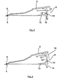
- FIGS. 6 and 7 represent the prior art generally known to provide a roof spoiler assembly for commercial vehicle cabs, in which a roof spoiler 100 is pivotable about a spoiler axis 103 as a rotation axis by means of a provided on the roof 101 of a cab pivot bearing assembly 102.
- a roof spoiler 100 is pivotable about a spoiler axis 103 as a rotation axis by means of a provided on the roof 101 of a cab pivot bearing assembly 102.
- Next is a spaced from the pivot bearing assembly arranged in the vehicle longitudinal direction behind adjusting 104, by means of the roof spoiler 100, as the FIGS. 6 and 7 it can be seen in different pivot position transferred and preserved there.
- the adjustment here consists of a strut joint arrangement with a first roof-side hinged strut 105, which is articulated via a pivot bearing 106 hinged to the roof, and a second strut 107, which is connected via a pivot bearing 108 hingedly connected to the first strut 105.
- These two pivot bearings 106, 108 are required in conjunction with the pivot bearing assembly 102 to facilitate easy and convenient pivotal movement of the roof spoiler 100 between the various pivot positions.
- two strut joint arrangements spaced apart from each other between the rear free roof spoiler end and the roof 101 are provided here (not shown) in the vehicle transverse direction.
- the first strut 105 is also designed as a telescopic strut, via which the adjustment is given.
- Such a structure has a certain reliability, but is technically complex component.
- a roof spoiler assembly for commercial vehicle cabs is already known in which a wind deflector designated roof spoiler is fastened by means of two front bearing on a roof of a cab.
- a carrying device is arranged on this, which is formed by a cross tube to which in turn centrally a support arm is attached.
- the support arm extends in the assembled state down and can be connected to a support which is fixedly arranged on the vehicle roof. This support is arranged as seen in the direction of travel behind the support arm and thus forms the outer part of the support device.
- a bracket is provided for height adjustment on the support arm, on which a shoe is attached.
- this shoe there is a threaded recess.
- This thread recess receives a screw with a washer on a bracket, so that the support between the bracket and the shoe can be arranged.
- the shoe surface is applicable to a curved surface of the support, wherein the curved surface is part of a cylindrical surface about the axis of rotation of the hinge device.
- the clamp is located on a convex surface of the support, which is parallel to the curved surface and centrally has a slot. At the end portions, the bracket has teeth that engage vertical teeth portions.
- the screw is released, the sliding shoe on the curved surface, the bracket on the convex surface and finally the screw in the slot moved to then at the desired height, the engaging portions (teeth) by engaging the screw with the then correspondingly associated tooth portions of the support into engagement.
- Such a structure is generally a relatively complex component and also has the risk that the screw may loosen during rough driving operation and thus can no longer reliably hold the safe, desired height fixation of the roof spoiler in position. In addition, there is the danger here that in case of loss of the screw and the clip is lost and thus without a corresponding Replacing this clamp no working roof spoiler is available anymore. Overall, it is therefore in such a structure to a less viable solution.
- GB 2 393 694 A a structure in which a roof spoiler with a leg surrounds a spoiler-side vertical element from the outside.
- the fixation takes place here via associated and aligned screw holes, through which a fastening screw is screwed through.
- the spoiler-side sliding guide member surrounds the roof-side sliding guide member in the vehicle longitudinal direction in the direction away from the spoiler axis seen from the outside, wherein the spoiler-side and the roof-side sliding guide part at their facing sides of the plant holding means by which the sliding guide parts are stable in their set position, said the holding means are formed by an overpressable connection with each other along the displacement path assignable locking elements and locking counter-elements.
- such a structure can be produced and implemented in a particularly simple and inexpensive manner with few components and, moreover, there is no danger of components possibly loosening during rough driving and thus leading to the loss of these components, which in turn leads to damage or a loss of function of the components Height adjustment and thus the roof spoiler assembly leads overall.
- a particularly functionally reliable pivoting of the roof spoiler which is easy to control in terms of component technology, is also possible, preferably around a spoiler axis formed by a pivot bearing arrangement, as the pivot axis.
- the use of a variety of component-intensive spherical bearings for the realization of the pivotal adjustment of the roof spoiler can thus be advantageously eliminated, so that according to the preferred embodiment only a single pivot bearing assembly for forming the spoiler axle needs to be provided, but not for the height adjustment of the roof spoiler.
- a particular advantage of such sliding guide is the fact that can be provided by the supporting abutment connection of the two sliding guide parts in a simple way a very reliable, less prone to interference, stable formable and easy-to-use adjustment.
- the supporting system connection of such a sliding guide causes namely a guided relative displacement of the two sliding guide parts to each other, which ensures the reliable and reliable pivoting of the roof spoiler.
- in conjunction with a according to a preferred embodiment arrangement of two such sliding guides on seen in the vehicle transverse direction in approximately opposite Dachspoilereckrand Schemeen thus a reliable, exactly synchronizedfeaturenverschwenkung the roof spoiler without additional connecting strut between the two sliding guide bearings achieve, as in the strut joint arrangement according to the previously appreciated prior art is required.
- the component diversity can be particularly reduced as such, so that the adjusting device according to the invention in the form of a sliding guide also easier to assemble and thus is less expensive to manufacture.
- the use of a plurality of spaced apart in the vehicle transverse direction and preferably in the vehicle longitudinal direction in each case an equal distance from the spoiler axle having sliding guides is a preferred embodiment, as a functionally reliable support of the roof spoiler in the predetermined pivoting position is possible.
- a functionally reliable support of the roof spoiler in the predetermined pivoting position is possible.
- a supporting frame system for a roof spoiler is provided with the roof spoiler assembly according to the invention, which allows a structurally simple manner with high reliability pivoting of the roof spoiler in different pivot positions.
- the spoiler-side and the roof-side sliding guide part lie flat against one another with their respective contact sides in each case. This provides a stable support of the sliding guide parts both in their rest position and during pivoting available.
- the latching structure is formed so that in the latched state latching elements in the form of latching elements engage in a form-fitting manner in the latching counter-elements formed in the form of latching grooves.
- a latching structure is simple, z. B. produced by stampings or the like.
- such a latching structure is very good überdrückbar especially in a more wavy configuration with a corresponding application of force.
- a very good and reliable control is possible on such locking structures, whether in the case of several sliding guides these each have a same height adjustment of the two sliding guide parts to each other. If appropriate, this can be optically supported by additional markings or corresponding shaping of individual latching structure areas.
- additional fasteners may optionally be provided, for. B. additional mounting screws or securing split or the like.
- the spoiler-side sliding guide member and the roof-side sliding guide member are each formed L-shaped such that in each case a first L-leg is firmly connected to the roof spoiler or the roof, while the respective second L-legs in the supporting abutment relative to each other displaceable abut each other ,
- Such a structure is component technology relatively easy to produce and in particular also allows easy installation in a series production.
- such sliding guide parts can basically be made of a low-cost plastic material.
- the roof-side sliding guide part is arranged on the rear roof edge region of a roof viewed in the vehicle longitudinal direction.
- This roof can be any type of roof, so be a normal roof, a flat roof or a high roof of a cab.
- the pivot bearing arrangement itself which is preferably formed by two hinges spaced apart from one another in the vehicle transverse direction, can additionally also have bearing blocks via which an advantageous and functionally reliable attachment of the hinges to the roof of the driver's cab can take place.
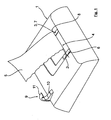
- the Fig. 1 shows schematically and in perspective a plan view of a high roof 1, which is part of a driver's cab or a driver's cab, not shown here.
- This roof 1 has, in a central region, a pivot bearing arrangement 4 formed by two hinges 2, 3 spaced apart in the vehicle transverse direction y, by means of which a roof spoiler 5 is pivotably connected to the high roof 1.
- the two hinges 2, 3 of the pivot bearing assembly 4 are mounted on bearing blocks 6, 7, which are shown here only extremely schematically, on the high roof 1 and form a spoiler axis 8 as a pivot axis for the roof spoiler 5.
- this sliding guide 9 is composed of a roof-side sliding guide member 10 and a spoiler-side sliding guide member 11, respectively.
- the roof-side sliding guide member 10 also has as the spoiler-side sliding guide member 11 has an L-shape. Both the roof-side sliding guide member 10 and the spoiler-side sliding guide member 11 are z. B. screwed to the roof 1 and the roof spoiler 5 firmly, in such a way that the two free L-legs 12, 13 abut with their mutually facing abutment surfaces in an abutment surface to each other, as in particular the FIGS. 2 and 3 can be seen.
- the spoiler-side sliding guide part 11 surrounds the roof-side sliding guide part 10 from behind and thus from the outside.
- the contact surfaces forming the contact surfaces 14, 15 have a circular arc geometry corresponding to a circular arc around the spoiler axis 8 as the center of the circle, so that at one in the Fig. 3 schematically shown pivoting adjustment of the roof spoiler 5 in the direction of arrow 16, the spoiler-side sliding guide member is displaced relative to the stationary roof-side sliding guide member 10 such that the roof spoiler 5 is pivoted upwards by a predetermined pivoting angle.
- the spoiler-side sliding guide member 11 slides with its L-leg 13 by means of its contact surface 15 by the predetermined displacement along the contact surface 14 of the L-leg 12 of the roof-side sliding guide part 10 and supported upward, wherein by the circular arc geometry, as described above has been ensured that a functionally safe succession-slipping of the two contact surfaces 14, 15 can be done without jamming or spreading.
- the two contact surfaces 14, 15 a latching structure 17 which is formed here by latching lugs 18 and locking grooves 19, wherein the latching lugs 18 are formed so that they engage positively and überdrückbar in the locking grooves 19.
- a reliable and secure positioning of the roof spoiler 5 in a desired pivoting position is possible, in particular a holding of the roof spoiler 5 in a desired pivoting position.
- a once taken detent position also not shown here with additional fixatives, z. B. a split pin or the like, are additionally fixed.
- z. B. in conjunction with the locking lugs 18 and / or locking grooves 19 additional markings may be provided which allow for a plurality of vehicle transverse direction y spaced sliding guides 9 a simple assignment of the respective locking lugs 18 and locking grooves 19 at a same height. This is also not shown here, for example, such markings can, however, by z. As numbers or the like can be specified.
Abstract
Description
Die Erfindung betrifft eine Dachspoileranordnung für Nutzfahrzeug-Fahrerhäuser nach dem Oberbegriff des Anspruchs 1.The invention relates to a roof spoiler arrangement for commercial vehicle cabs according to the preamble of claim 1.
Es ist allgemein bekannt, Nutzfahrzeuge, insbesondere Lkw's für den Fernverkehr, mit einem Dachspoiler auszustatten, um die Aerodynamik des Fahrzeugs zu verbessern. Um weiter den Höhenunterschied des Fahrerhauses bzw. der Fahrerkabine zu anschließenden, festen oder beweglichen, höheren oder breiteren Aufbauten bzw. Auflegern ausgleichen zu können, ist es erforderlich, dass der Dachspoiler selbst als in der Höhe einstellbar ausgelegt ist.It is well known to equip utility vehicles, especially long-haul trucks, with a roof spoiler to improve the aerodynamics of the vehicle. In order to be able to further compensate for the difference in height of the driver's cab or the driver's cab, to compensate fixed or movable, higher or wider superstructures or semi-trailers, it is necessary for the roof spoiler itself to be designed to be adjustable in height.
Beispielsweise ist es aus dem durch die
Aus der
Ein derartiger Aufbau ist insgesamt gesehen relativ bauteilaufwändig und weist zudem die Gefahr auf, dass sich die Schraube während des rauen Fahrbetriebs gegebenenfalls lockern kann und dadurch die sichere, gewünschte Höhenfixierung des Dachspoilers nicht mehr funktionssicher in Position halten kann. Zudem besteht hier die Gefahr, dass bei einem Verlust der Schraube auch die Klammer verloren geht und dadurch ohne ein entsprechendes Ersetzen dieser Klammer kein funktionierender Dachspoiler mehr zur Verfügung steht. Insgesamt handelt es sich daher bei einem derartigen Aufbau um eine wenig praktikable Lösung.Such a structure is generally a relatively complex component and also has the risk that the screw may loosen during rough driving operation and thus can no longer reliably hold the safe, desired height fixation of the roof spoiler in position. In addition, there is the danger here that in case of loss of the screw and the clip is lost and thus without a corresponding Replacing this clamp no working roof spoiler is available anymore. Overall, it is therefore in such a structure to a less viable solution.
Weiter zeigt die
Demgegenüber ist es Aufgabe der vorliegenden Erfindung, eine Dachspoileranordnung für Nutzfahrzeug-Fahrerhäuser zur Verfügung zu stellen, mittels der eine Höhenverstellung eines Dachspoilers auf einfache und funktionssichere Weise mit geringem Bauteilaufwand möglich ist.In contrast, it is an object of the present invention to provide a roof spoiler assembly for commercial vehicle cabs available by means of a height adjustment of a roof spoiler in a simple and reliable manner with low component cost is possible.
Diese Aufgabe wird gelöst mit den Merkmalen des Patentanspruchs 1. Vorteilhafte Ausgestaltungen hierzu sind Gegenstand der darauf rückbezogenen Unteransprüche.This object is achieved with the features of claim 1. Advantageous embodiments thereof are the subject of the dependent claims.
Gemäß Anspruch 1 umgreift das spoilerseitige Schiebeführungsteil das dachseitige Schiebeführungsteil in Fahrzeuglängsrichtung in Richtung von der Spoilerachse weg gesehen von außen her, wobei das spoilerseitige und das dachseitige Schiebeführungsteil an ihren einander zugewandten Anlageseiten Haltemittel aufweisen, mittels denen die Schiebeführungsteile in ihrer eingestellten Position haltbar sind, wobei die Haltemittel durch eine überdrückbare Verbindung mit einander entlang des Verschiebeweges zuordenbaren Rastelementen und Rastgegenelementen gebildet sind.According to claim 1, the spoiler-side sliding guide member surrounds the roof-side sliding guide member in the vehicle longitudinal direction in the direction away from the spoiler axis seen from the outside, wherein the spoiler-side and the roof-side sliding guide part at their facing sides of the plant holding means by which the sliding guide parts are stable in their set position, said the holding means are formed by an overpressable connection with each other along the displacement path assignable locking elements and locking counter-elements.
Mit einer derartigen erfindungsgemäßen Ausgestaltung ergibt sich eine besonders stabile, funktionssichere und zuverlässige Abstützung des Dachspoilers sowie Anlageverbindung der beiden Schiebeführungsteile aneinander, da mit einem derartigen Aufbau eine gewisse "Spannung" im Bereich der Schiebeführung aufgebaut werden kann, die die zuverlässige und funktionssichere Halterung sowie Abstützung der beiden Schiebeführungsteile aneinander und damit des Dachspoilers in einer einmal eingestellten Schwenkposition sicherstellt. Zudem ist eine derartige Anordnung bei einer entsprechenden Kraftaufbringung sehr gut überdrückbar, so dass eine einfache und funktionssichere Höhenverstellung der beiden Schiebeführungsteile zueinander möglich ist.With such a configuration according to the invention, a particularly stable, reliable and reliable support of the roof spoiler and system connection of the two sliding guide parts together, since with such a structure, a certain "voltage" in the sliding guide can be constructed, the reliable and functionally reliable support and support the two sliding guide parts together and thus the roof spoiler ensures in a once set pivoting position. In addition, such an arrangement is very well überdrückbar with a corresponding force application, so that a simple and reliable height adjustment of the two sliding guide parts to each other is possible.
Des Weiteren kann ein derartiger Aufbau besonders einfach und preiswert mit wenig Bauteilen hergestellt und realisiert werden und besteht überdies keine Gefahr, dass sich im rauen Fahrbetrieb gegebenenfalls Bauteile lösen und damit zum Verlust dieser Bauteile führen können, was wiederum zu einer Beschädigung bzw. einem Funktionsverlust der Höhenverstelleinrichtung und damit der Dachspoileranordnung insgesamt führt.Furthermore, such a structure can be produced and implemented in a particularly simple and inexpensive manner with few components and, moreover, there is no danger of components possibly loosening during rough driving and thus leading to the loss of these components, which in turn leads to damage or a loss of function of the components Height adjustment and thus the roof spoiler assembly leads overall.
Mit einer derartigen erfindungsgemäßen Lösung wird weiter ein besonders funktionssicheres und bauteiltechnisch einfach beherrschbares Verschwenken des Dachspoilers, bevorzugt um eine durch eine Schwenklageranordnung gebildete Spoilerachse als Schwenkachse möglich. Der Einsatz einer Vielzahl von bauteilintensiven Gelenklagern zur Realisierung der Schwenkverstellung des Dachspoilers kann somit vorteilhaft entfallen, so dass gemäß der bevorzugten Ausgestaltung lediglich noch eine einzige Schwenklageranordnung zur Ausbildung der Spoilerachse vorgesehen zu werden braucht, nicht jedoch für die Höhenverstellung des Dachspoilers.With such a solution according to the invention, a particularly functionally reliable pivoting of the roof spoiler, which is easy to control in terms of component technology, is also possible, preferably around a spoiler axis formed by a pivot bearing arrangement, as the pivot axis. The use of a variety of component-intensive spherical bearings for the realization of the pivotal adjustment of the roof spoiler can thus be advantageously eliminated, so that according to the preferred embodiment only a single pivot bearing assembly for forming the spoiler axle needs to be provided, but not for the height adjustment of the roof spoiler.
Ein besonderer Vorteil einer derartigen Schiebeführung ist darin zu sehen, dass durch die abstützende Anlageverbindung der beiden Schiebeführungsteile auf einfache Weise eine sehr funktionssichere, wenig störanfällige, stabil ausbildbare und einfach zu bedienende Verstelleinrichtung zur Verfügung gestellt werden kann. Die abstützende Anlageverbindung einer derartigen Schiebeführung bewirkt nämlich eine geführte Relativverschiebung der beiden Schiebeführungsteile zueinander, die die zuverlässige und funktionssichere Verschwenkung des Dachspoilers sicherstellt. Insbesondere in Verbindung mit einer gemäß einer bevorzugten Ausführungsform-Anordnung von zwei derartigen Schiebeführungen an in Fahrzeugquerrichtung gesehen in etwa gegenüberliegenden Dachspoilereckrandbereichen lässt sich somit eine zuverlässige, genau synchronisierte Höhenverschwenkung des Dachspoilers ohne zusätzliche Verbindungsstrebe zwischen den beiden Schiebeführungslagern erzielen, wie diese bei der Strebengelenkanordnung gemäß dem zuvor gewürdigten Stand der Technik erforderlich ist. Das heißt, dass mit der erfindungsgemäßen Lösung besonders vorteilhaft die Bauteilvielfalt als solche reduziert werden kann, so dass die erfindungsgemäße Verstelleinrichtung in Form einer Schiebeführung auch einfacher zu montieren und damit insgesamt preiswerter in der Herstellung ist.A particular advantage of such sliding guide is the fact that can be provided by the supporting abutment connection of the two sliding guide parts in a simple way a very reliable, less prone to interference, stable formable and easy-to-use adjustment. The supporting system connection of such a sliding guide causes namely a guided relative displacement of the two sliding guide parts to each other, which ensures the reliable and reliable pivoting of the roof spoiler. In particular, in conjunction with a according to a preferred embodiment arrangement of two such sliding guides on seen in the vehicle transverse direction in approximately opposite Dachspoilereckrandbereichen thus a reliable, exactly synchronized Höhenverschwenkung the roof spoiler without additional connecting strut between the two sliding guide bearings achieve, as in the strut joint arrangement according to the previously appreciated prior art is required. This means that with the solution according to the invention, the component diversity can be particularly reduced as such, so that the adjusting device according to the invention in the form of a sliding guide also easier to assemble and thus is less expensive to manufacture.
Wie eben ausgeführt, stellt die Verwendung von mehreren in Fahrzeugquerrichtung beabstandeten sowie bevorzugt in Fahrzeuglängsrichtung jeweils einen gleichen Abstand von der Spoilerachse aufweisenden Schiebeführungen eine bevorzugte Ausgestaltung dar, da hierdurch eine funktionssichere Abstützung des Dachspoilers in der vorgegebenen Verschwenkposition möglich ist. Grundsätzlich könnte jedoch auch, z. B. in Verbindung mit einer in Fahrzeugquerrichtung gesehen breiteren Ausgestaltung und Dimensionierung der Schiebeführung auch eine solche Lösung möglich sein, bei der lediglich eine einzige Schiebeführung vorgesehen ist, z. B. in einem bezogen auf die Fahrzeugquerrichtung mittleren Bereich des Dachspoilers.As just stated, the use of a plurality of spaced apart in the vehicle transverse direction and preferably in the vehicle longitudinal direction in each case an equal distance from the spoiler axle having sliding guides is a preferred embodiment, as a functionally reliable support of the roof spoiler in the predetermined pivoting position is possible. In principle, however, could also, for. B. in connection with a vehicle transverse direction seen wider design and dimensioning of the sliding guide also be possible such a solution in which only a single sliding guide is provided, for. B. in a relative to the vehicle transverse direction middle region of the roof spoiler.
Insgesamt wird daher mit der erfindungsgemäßen Dachspoileranordnung ein Traggestellsystem für einen Dachspoiler zur Verfügung gestellt, das auf baulich einfache Weise mit hoher Funktionssicherheit ein Verschwenken des Dachspoilers in unterschiedliche Schwenkpositionen ermöglicht.Overall, therefore, a supporting frame system for a roof spoiler is provided with the roof spoiler assembly according to the invention, which allows a structurally simple manner with high reliability pivoting of the roof spoiler in different pivot positions.
Für eine flächige Anlageverbindung liegen das spoilerseitige und das dachseitige Schiebeführungsteil mit ihren jeweiligen Anlageseiten jeweils flächig aneinander an. Damit wird eine stabile Abstützung der Schiebeführungsteile sowohl in deren Ruhestellung als auch während des Verschwenkens zur Verfügung gestellt.For a planar contact connection, the spoiler-side and the roof-side sliding guide part lie flat against one another with their respective contact sides in each case. This provides a stable support of the sliding guide parts both in their rest position and during pivoting available.
Beispielsweise ist die Raststruktur so ausgebildet, dass in Form von Rastnasen ausgebildete Rastelemente im verrasteten Zustand formschlüssig in die in Form von Rastnuten ausgebildeten Rastgegenelemente eingreifen. Eine derartige Raststruktur ist einfach, z. B. durch Verprägungen oder dergleichen herstellbar. Zudem ist eine derartige Raststruktur insbesondere bei einer mehr wellenförmigen Ausgestaltung bei einer entsprechenden Kraftaufbringung sehr gut überdrückbar. Außerdem ist über derartige Raststrukturen eine sehr gute und zuverlässige Kontrolle möglich, ob im Falle von mehreren Schiebeführungen diese jeweils eine gleiche Höhenverstellung der beiden Schiebeführungsteile zueinander aufweisen. Dies kann gegebenenfalls noch durch zusätzliche Markierungen oder entsprechende Formgebung einzelner Raststrukturbereiche optisch unterstützt werden. Abgesehen von den eben genannten Vorteilen ist mit einer derartigen Raststruktur selbstverständlich auch eine besonders zuverlässige und sichere Halterung der Schiebeführungsteile in ihrer eingestellten Position möglich, wobei hier gegebenenfalls noch zusätzliche Befestigungselemente vorgesehen sein können, z. B. zusätzliche Befestigungsschrauben oder Sicherungssplinte oder dergleichen.For example, the latching structure is formed so that in the latched state latching elements in the form of latching elements engage in a form-fitting manner in the latching counter-elements formed in the form of latching grooves. Such a latching structure is simple, z. B. produced by stampings or the like. In addition, such a latching structure is very good überdrückbar especially in a more wavy configuration with a corresponding application of force. In addition, a very good and reliable control is possible on such locking structures, whether in the case of several sliding guides these each have a same height adjustment of the two sliding guide parts to each other. If appropriate, this can be optically supported by additional markings or corresponding shaping of individual latching structure areas. Apart from the just mentioned Benefits with such a locking structure of course, a particularly reliable and secure mounting of the sliding guide parts in their set position possible, in which case additional fasteners may optionally be provided, for. B. additional mounting screws or securing split or the like.
Bevorzugt sind das spoilerseitige Schiebeführungsteil und das dachseitige Schiebeführungsteil jeweils L-förmig ausgebildet dergestalt, dass jeweils ein erster L-Schenkel fest mit dem Dachspoiler bzw. dem Dach verbunden ist, während die jeweils zweiten L-Schenkel in der abstützenden Anlageverbindung relativ zueinander verlagerbar aneinander anliegen. Ein derartiger Aufbau ist bauteiltechnisch relativ einfach herstellbar und ermöglicht insbesondere auch eine einfache Montage im Rahmen einer Serienfertigung. Zudem können derartige Schiebeführungsteile grundsätzlich auch aus einem preiswerten Kunststoffmaterial hergestellt sein.Preferably, the spoiler-side sliding guide member and the roof-side sliding guide member are each formed L-shaped such that in each case a first L-leg is firmly connected to the roof spoiler or the roof, while the respective second L-legs in the supporting abutment relative to each other displaceable abut each other , Such a structure is component technology relatively easy to produce and in particular also allows easy installation in a series production. In addition, such sliding guide parts can basically be made of a low-cost plastic material.
Für eine besonders vorteilhafte Abstützung ist gemäß einer weiteren bevorzugten Ausgestaltung der Erfindung vorgesehen, dass das dachseitige Schiebeführungsteil am in Fahrzeuglängsrichtung gesehen hinteren Dachrandbereich eines Daches angeordnet ist. Dieses Dach kann jede Art von Dach sein, also ein Normaldach, ein Flachdach oder ein Hochdach eines Führerhauses sein.For a particularly advantageous support, it is provided according to a further preferred embodiment of the invention that the roof-side sliding guide part is arranged on the rear roof edge region of a roof viewed in the vehicle longitudinal direction. This roof can be any type of roof, so be a normal roof, a flat roof or a high roof of a cab.
Die Schwenklageranordnung selbst, die bevorzugt durch zwei voneinander in Fahrzeugquerrichtung beabstandete Scharniere gebildet ist, kann zudem zusätzlich noch Lagerböcke aufweisen, über die eine vorteilhafte und funktionssichere Befestigung der Scharniere am Dach des Fahrerhauses erfolgen kann.The pivot bearing arrangement itself, which is preferably formed by two hinges spaced apart from one another in the vehicle transverse direction, can additionally also have bearing blocks via which an advantageous and functionally reliable attachment of the hinges to the roof of the driver's cab can take place.
Die Erfindung wird nachfolgend anhand einer Zeichnung näher erläutert.The invention will be explained in more detail with reference to a drawing.
Es zeigen:
- Fig. 1
- schematisch eine perspektivische Draufsicht auf eine erfindungsgemäße Dach- spoileranordnung,
- Fig. 2
- schematisch eine Prinzipskizze einer erfindungsgemäßen Dachspoileranordnung in einer Grundposition,
- Fig. 3
- schematisch eine Prinzipskizze der Dachspoileranordnung gemäß
Fig. 2 in einer höhenverschwenkten Position des Dachspoilers, - Fig. 4
- eine äußerst schematische, vergrößerte Detailansicht einer Einzelheit der Anla- geverbindung zwischen spoilerseitigem Schiebeführungsteil und dachseitigem Schiebeführungsteil,
- Fig. 5
- eine schematisch vergrößerte Detailansicht der Einzelheit A der
Fig. 4 , - Fig. 6
- eine Dachspoileranordnung gemäß dem Stand der Technik in einer Grundpositi- on, und
- Fig. 7
- eine Dachspoileranordnung gemäß dem Stand der Technik in einer höhenver- schwenkten Position.
- Fig. 1
- 1 is a schematic top view of a roof spoiler arrangement according to the invention;
- Fig. 2
- schematically a schematic diagram of a roof spoiler assembly according to the invention in a basic position,
- Fig. 3
- schematically a schematic diagram of the roof spoiler assembly according to
Fig. 2 in a height-pivoted position of the roof spoiler, - Fig. 4
- an extremely schematic, enlarged detail view of a detail of the system connection between the spoiler-side sliding guide part and roof-side sliding guide part,
- Fig. 5
- a schematically enlarged detail view of the detail A of
Fig. 4 . - Fig. 6
- a roof spoiler assembly according to the prior art in a basic position, and
- Fig. 7
- a roof spoiler assembly according to the prior art in a height-pivoted position.
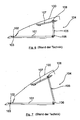
Die
Die beiden Scharniere 2, 3 der Schwenklageranordnung 4 sind über Lagerböcke 6, 7, die hier nur äußerst schematisch dargestellt sind, am Hochdach 1 befestigt und bilden eine Spoilerachse 8 als Schwenkachse für den Dachspoiler 5 aus.The two hinges 2, 3 of the
In Fahrzeuglängsachsenrichtung x gesehen beabstandet hinter der Schwenklageranordnung 4 ist zu beiden Seiten des Dachspoilers 5 jeweils eine Schiebeführung 9 vorgesehen, von der in der Darstellung der
Wie dies insbesondere auch aus den Prinzipskizzen der
Die die Anlagenflächen 14, 15 ausbildenden Anlageflächen weisen eine Kreisbogengeometrie entsprechend einem Kreisbogen um die Spoilerachse 8 als Kreismittelpunkt auf, so dass bei einer in der
Bei dieser Relativverschiebung gleitet das spoilerseitige Schiebeführungsteil 11 mit seinem L-Schenkel 13 mittels seiner Anlagefläche 15 um den vorgegebenen Verschiebeweg entlang der Anlagefläche 14 des L-Schenkels 12 des dachseitigen Schiebeführungsteils 10 geführt und abgestützt nach oben, wobei durch die Kreisbogengeometrie, wie sie zuvor beschrieben worden ist, sichergestellt ist, dass ein funktionssicheres Aufeinander-Abgleiten der beiden Anlageflächen 14, 15 ohne Verklemmungen oder Spreizungen erfolgen kann.In this relative displacement, the spoiler-side sliding
Wie dies weiter in den
Mit einer derartigen Raststruktur wird eine zuverlässige und sichere Positionierung des Dachspoilers 5 in einer gewünschten Verschwenkposition möglich, insbesondere ein Halten des Dachspoilers 5 in einer gewünschten Schwenkposition. Gegebenenfalls kann eine einmal eingenommene Rastposition auch noch mit hier nicht dargestellten zusätzlichen Fixiermitteln, z. B. einer Splintsicherung oder dergleichen, zusätzlich fixiert werden.With such a latching structure, a reliable and secure positioning of the
Des weiteren können z. B. in Verbindung mit den Rastnasen 18 und/oder Rastnuten 19 zusätzliche Markierungen vorgesehen sein, die bei mehreren in Fahrzeugquerrichtung y voneinander beabstandeten Schiebeführungen 9 eine einfache Zuordnung der jeweiligen Rastnasen 18 und Rastnuten 19 auf einer gleichen Höhe ermöglichen. Dies ist hier ebenfalls nicht mit dargestellt, beispielsweise können derartige Markierungen jedoch durch z. B. Ziffern oder dergleichen angegeben werden.Furthermore, z. B. in conjunction with the locking lugs 18 and / or locking
Claims (10)
- Roof spoiler array for commercial vehicle driver cabs,
with a roof spoiler (5), with a pivot bearing array (4) that can be provided on the roof (1) of a driver cab, by means of which pivot bearing array the roof spoiler can be mounted pivotable about a spoiler axis (8), as well as an adjusting fixture, by means of which adjusting fixture the roof spoiler (5) can be moved and held in various pivot positions, whereby the adjusting fixture is designed as a sliding guide (9) with a sliding guide part (10, 11) on the spoiler side and on the roof side, which sliding parts lie against one another in a supporting contact connection when the roof spoiler (5) is pivoted and can be displaced relative to one another along a predetermined displacement path, whereby each sliding guide part (10, 11) on the spoiler side and on the roof side features a circular arc geometry corresponding to a circular arc about the spoiler axis (8) as the centre of a circle in the area of their contact sides (14, 15) forming the contact connection and facing one another, and whereby the sliding guide part (11) on the spoiler side is firmly attached to the roof spoiler (5), whilst the sliding guide part (10) on the roof side can be firmly attached to the roof (1) of the driver cab,
characterised in that
the sliding guide part (11) on the spoiler side encloses the sliding guide part (10) on the roof side from the outside in the longitudinal direction of the vehicle when viewed away from the spoiler axis (8), and
the sliding guide part (10, 11) on the spoiler side and on the roof side feature holding means (17) on their contact sides (14, 15) that face one another, by means of which holding means the sliding guide parts (10, 11) can be held in their set position, whereby the holding means are formed by a pressable connection (17) with detent elements (18) and detent counter elements (19) that can be assigned to each other along the displacement path. - Roof spoiler array in accordance with claim 1, characterised in that the sliding guide part (10, 11) on the spoiler side and on the roof side each feature contact surfaces (14, 15) for a flush contact connection with each another.
- Roof spoiler array in accordance with claim 1 or 2, characterised in that the detent structure (17) is designed such that the detent elements designed in the form of detent lugs (18) engage positively when in their detented state in the detent counter elements designed in the form of detent grooves (19).
- Roof spoiler array in accordance with one of claims 1 to 3, characterised in that several, in particular two, sliding guides (9) are provided that are distanced from one another in the transverse direction of the vehicle by a predetermined distance and that are distanced by an identical distance respectively from the spoiler axis (8) in the longitudinal direction of the vehicle.
- Roof spoiler array in accordance with one of claims 1 to 4, characterised in that the detent structure (17) is designed and/or features additional markings such that in the case of several sliding guides (9), a visual and/or haptically supported assignment of the detent elements (18) and the detent counter elements (19) to the various sliding guides (9) at the same height can be carried out.
- Roof spoiler array in accordance with claim 4 or claim 5, characterised in that two sliding guides (9) are provided that are distanced from one another in the transverse direction of the vehicle, which sliding guides are further distanced from the spoiler axis (8) in the longitudinal direction of the vehicle such that these sliding guides are positioned in the rear corner edge area of the roof spoiler (5) relative to the longitudinal direction of the vehicle.
- Roof spoiler array in accordance with one of claims 1 to 6, characterised in that the sliding guide part (11) on the spoiler side and the sliding guide part (10) on the roof side each feature an L-shape, such that a first L-shank is firmly attached to the roof spoiler (5) or the roof (1) in each case, whilst the respective second L-shanks (12, 13) lie against one another and can be displaced relative to each other in the supporting contact connection.
- Roof spoiler array in accordance with one of claims 1 to 7, characterised in that the sliding guide part (10) on the roof side can be positioned in the rear roof edge area of a roof (1) relative to the longitudinal direction of the vehicle.
- Roof spoiler array in accordance with one of claims 1 to 8, characterised in that the pivot bearing array (4) is formed by several, in particular two, hinges (2, 3) distanced from one another in the transverse direction of the vehicle, to which hinges the roof spoiler (5) is hinged pivotable with a front roof spoiler edge area seen in the longitudinal direction of the vehicle and which hinges form the spoiler axis (8).
- Roof spoiler array in accordance with claim 9, characterised in that the hinges are fixed to the roof (1) of the driver cab by means of mounting brackets (6, 7).
Priority Applications (1)
| Application Number | Priority Date | Filing Date | Title |
|---|---|---|---|
| PL08012205T PL2020366T3 (en) | 2007-08-02 | 2008-07-07 | Roof spoiler array for commercial vehicle driver cabs |
Applications Claiming Priority (1)
| Application Number | Priority Date | Filing Date | Title |
|---|---|---|---|
| DE102007036335A DE102007036335A1 (en) | 2007-08-02 | 2007-08-02 | Roof spoiler arrangement for commercial vehicle cabs |
Publications (3)
| Publication Number | Publication Date |
|---|---|
| EP2020366A2 EP2020366A2 (en) | 2009-02-04 |
| EP2020366A3 EP2020366A3 (en) | 2009-04-08 |
| EP2020366B1 true EP2020366B1 (en) | 2010-04-07 |
Family
ID=40020221
Family Applications (1)
| Application Number | Title | Priority Date | Filing Date |
|---|---|---|---|
| EP08012205A Active EP2020366B1 (en) | 2007-08-02 | 2008-07-07 | Roof spoiler array for commercial vehicle driver cabs |
Country Status (4)
| Country | Link |
|---|---|
| EP (1) | EP2020366B1 (en) |
| AT (1) | ATE463411T1 (en) |
| DE (2) | DE102007036335A1 (en) |
| PL (1) | PL2020366T3 (en) |
Cited By (1)
| Publication number | Priority date | Publication date | Assignee | Title |
|---|---|---|---|---|
| DE102019007558A1 (en) * | 2019-10-30 | 2021-05-06 | Man Truck & Bus Se | Modular system and connection device for motor vehicle air control elements |
Families Citing this family (3)
| Publication number | Priority date | Publication date | Assignee | Title |
|---|---|---|---|---|
| DE102019008489A1 (en) | 2019-12-06 | 2021-06-10 | Man Truck & Bus Se | Motor vehicle with roof spoiler |
| DE102019008488A1 (en) * | 2019-12-06 | 2021-06-10 | Man Truck & Bus Se | Motor vehicle with window cleaning system |
| DE102022123922A1 (en) | 2022-09-19 | 2024-03-21 | Quantron Ag | SPOILER ARRANGEMENT FOR A VEHICLE AND VEHICLE HAVING SUCH A SPOILER ARRANGEMENT |
Family Cites Families (4)
| Publication number | Priority date | Publication date | Assignee | Title |
|---|---|---|---|---|
| US4082340A (en) * | 1976-08-03 | 1978-04-04 | Alexander Taylor | Air current deflecting device |
| DE19825252A1 (en) | 1998-06-05 | 1999-12-09 | Fritzmeier Composite Gmbh & Co | Vertically adjustable wind deflector for motor vehicles |
| AT407628B (en) * | 1999-04-08 | 2001-05-25 | Steyr Nutzfahrzeuge | BRACKET FOR A ROOF SPOILER ARRANGED ON THE CAB OF A TRUCK |
| GB0222735D0 (en) | 2002-10-01 | 2002-11-06 | Bacon Andy | Aerodynamic fairing |
-
2007
- 2007-08-02 DE DE102007036335A patent/DE102007036335A1/en not_active Withdrawn
-
2008
- 2008-07-07 EP EP08012205A patent/EP2020366B1/en active Active
- 2008-07-07 PL PL08012205T patent/PL2020366T3/en unknown
- 2008-07-07 AT AT08012205T patent/ATE463411T1/en active
- 2008-07-07 DE DE502008000518T patent/DE502008000518D1/en active Active
Cited By (2)
| Publication number | Priority date | Publication date | Assignee | Title |
|---|---|---|---|---|
| DE102019007558A1 (en) * | 2019-10-30 | 2021-05-06 | Man Truck & Bus Se | Modular system and connection device for motor vehicle air control elements |
| WO2021083708A1 (en) | 2019-10-30 | 2021-05-06 | Man Truck & Bus Se | Modular system and connection device for motor vehicle air-guiding elements |
Also Published As
| Publication number | Publication date |
|---|---|
| EP2020366A2 (en) | 2009-02-04 |
| EP2020366A3 (en) | 2009-04-08 |
| DE102007036335A1 (en) | 2009-03-05 |
| DE502008000518D1 (en) | 2010-05-20 |
| PL2020366T3 (en) | 2010-09-30 |
| ATE463411T1 (en) | 2010-04-15 |
Similar Documents
| Publication | Publication Date | Title |
|---|---|---|
| EP1878622B1 (en) | Mounting device for a mounted part of a motor vehicle | |
| DE102008047249A1 (en) | Backrest structure for a motor vehicle seat | |
| EP1884410A2 (en) | Rear load carrier | |
| EP2817195B1 (en) | Steering column for a motor vehicle with a support part | |
| EP2020366B1 (en) | Roof spoiler array for commercial vehicle driver cabs | |
| DE102011088852B4 (en) | Air deflector for a vehicle | |
| DE2551335A1 (en) | SUNROOF FOR MOTOR VEHICLES | |
| WO2013068317A2 (en) | Screen printing doctor blade and device for screen printing | |
| EP3183133B1 (en) | Slider for guiding a movable member | |
| EP2216205B1 (en) | Roof carrier for motor vehicles | |
| DE10250905B4 (en) | Adjustment device for a steering wheel of a truck | |
| DE102015201365A1 (en) | Underrun protection device | |
| EP3456591A1 (en) | Component system for fixing a trim part and motor vehicle | |
| EP3825175B1 (en) | Vehicle seat | |
| DE102007024570B4 (en) | Hinge for a motor vehicle door | |
| EP0328867B1 (en) | Vehicle sun visor | |
| DE102006046266B4 (en) | Clamping device for a front hood | |
| EP0327728A1 (en) | Vehicle bumper device | |
| DE102019200488A1 (en) | Steering column for a motor vehicle | |
| EP4051559B1 (en) | Modular system and connection device for motor vehicle air-guiding elements | |
| DE10320820B4 (en) | Swivel bearing device for an adjustable component and method for mounting such a pivot bearing device | |
| DE2833953C2 (en) | Device for reducing the air resistance of a truck | |
| DE102004058991A1 (en) | Wind deflecting element for windscreen of convertible, comprising hydraulically operated lifting unit with three lever linkage | |
| DE102008051754B4 (en) | Adjustable roof assembly for a convertible | |
| DE102010050015A1 (en) | Locking device for steering column of motor vehicle, has catch element with catch element-sided sliding function surface, where catch element is integrally formed with clamping surface element |
Legal Events
| Date | Code | Title | Description |
|---|---|---|---|
| PUAI | Public reference made under article 153(3) epc to a published international application that has entered the european phase |
Free format text: ORIGINAL CODE: 0009012 |
|
| AK | Designated contracting states |
Kind code of ref document: A2 Designated state(s): AT BE BG CH CY CZ DE DK EE ES FI FR GB GR HR HU IE IS IT LI LT LU LV MC MT NL NO PL PT RO SE SI SK TR |
|
| AX | Request for extension of the european patent |
Extension state: AL BA MK RS |
|
| PUAL | Search report despatched |
Free format text: ORIGINAL CODE: 0009013 |
|
| AK | Designated contracting states |
Kind code of ref document: A3 Designated state(s): AT BE BG CH CY CZ DE DK EE ES FI FR GB GR HR HU IE IS IT LI LT LU LV MC MT NL NO PL PT RO SE SI SK TR |
|
| AX | Request for extension of the european patent |
Extension state: AL BA MK RS |
|
| 17P | Request for examination filed |
Effective date: 20090424 |
|
| 17Q | First examination report despatched |
Effective date: 20090605 |
|
| AKX | Designation fees paid |
Designated state(s): AT BE BG CH CY CZ DE DK EE ES FI FR GB GR HR HU IE IS IT LI LT LU LV MC MT NL NO PL PT RO SE SI SK TR |
|
| GRAP | Despatch of communication of intention to grant a patent |
Free format text: ORIGINAL CODE: EPIDOSNIGR1 |
|
| GRAS | Grant fee paid |
Free format text: ORIGINAL CODE: EPIDOSNIGR3 |
|
| GRAA | (expected) grant |
Free format text: ORIGINAL CODE: 0009210 |
|
| AK | Designated contracting states |
Kind code of ref document: B1 Designated state(s): AT BE BG CH CY CZ DE DK EE ES FI FR GB GR HR HU IE IS IT LI LT LU LV MC MT NL NO PL PT RO SE SI SK TR |
|
| REG | Reference to a national code |
Ref country code: GB Ref legal event code: FG4D Free format text: NOT ENGLISH |
|
| REG | Reference to a national code |
Ref country code: CH Ref legal event code: EP |
|
| REG | Reference to a national code |
Ref country code: NL Ref legal event code: T3 |
|
| REG | Reference to a national code |
Ref country code: IE Ref legal event code: FG4D Free format text: LANGUAGE OF EP DOCUMENT: GERMAN |
|
| REF | Corresponds to: |
Ref document number: 502008000518 Country of ref document: DE Date of ref document: 20100520 Kind code of ref document: P |
|
| REG | Reference to a national code |
Ref country code: SE Ref legal event code: TRGR |
|
| PG25 | Lapsed in a contracting state [announced via postgrant information from national office to epo] |
Ref country code: SI Free format text: LAPSE BECAUSE OF FAILURE TO SUBMIT A TRANSLATION OF THE DESCRIPTION OR TO PAY THE FEE WITHIN THE PRESCRIBED TIME-LIMIT Effective date: 20100407 |
|
| LTIE | Lt: invalidation of european patent or patent extension |
Effective date: 20100407 |
|
| REG | Reference to a national code |
Ref country code: PL Ref legal event code: T3 |
|
| REG | Reference to a national code |
Ref country code: IE Ref legal event code: FD4D |
|
| PG25 | Lapsed in a contracting state [announced via postgrant information from national office to epo] |
Ref country code: NO Free format text: LAPSE BECAUSE OF FAILURE TO SUBMIT A TRANSLATION OF THE DESCRIPTION OR TO PAY THE FEE WITHIN THE PRESCRIBED TIME-LIMIT Effective date: 20100707 Ref country code: LT Free format text: LAPSE BECAUSE OF FAILURE TO SUBMIT A TRANSLATION OF THE DESCRIPTION OR TO PAY THE FEE WITHIN THE PRESCRIBED TIME-LIMIT Effective date: 20100407 Ref country code: ES Free format text: LAPSE BECAUSE OF FAILURE TO SUBMIT A TRANSLATION OF THE DESCRIPTION OR TO PAY THE FEE WITHIN THE PRESCRIBED TIME-LIMIT Effective date: 20100718 |
|
| PG25 | Lapsed in a contracting state [announced via postgrant information from national office to epo] |
Ref country code: HR Free format text: LAPSE BECAUSE OF FAILURE TO SUBMIT A TRANSLATION OF THE DESCRIPTION OR TO PAY THE FEE WITHIN THE PRESCRIBED TIME-LIMIT Effective date: 20100407 Ref country code: FI Free format text: LAPSE BECAUSE OF FAILURE TO SUBMIT A TRANSLATION OF THE DESCRIPTION OR TO PAY THE FEE WITHIN THE PRESCRIBED TIME-LIMIT Effective date: 20100407 Ref country code: LV Free format text: LAPSE BECAUSE OF FAILURE TO SUBMIT A TRANSLATION OF THE DESCRIPTION OR TO PAY THE FEE WITHIN THE PRESCRIBED TIME-LIMIT Effective date: 20100407 Ref country code: IS Free format text: LAPSE BECAUSE OF FAILURE TO SUBMIT A TRANSLATION OF THE DESCRIPTION OR TO PAY THE FEE WITHIN THE PRESCRIBED TIME-LIMIT Effective date: 20100807 |
|
| PG25 | Lapsed in a contracting state [announced via postgrant information from national office to epo] |
Ref country code: CY Free format text: LAPSE BECAUSE OF FAILURE TO SUBMIT A TRANSLATION OF THE DESCRIPTION OR TO PAY THE FEE WITHIN THE PRESCRIBED TIME-LIMIT Effective date: 20100609 |
|
| BERE | Be: lapsed |
Owner name: MAN NUTZFAHRZEUGE A.G. Effective date: 20100731 |
|
| PG25 | Lapsed in a contracting state [announced via postgrant information from national office to epo] |
Ref country code: DK Free format text: LAPSE BECAUSE OF FAILURE TO SUBMIT A TRANSLATION OF THE DESCRIPTION OR TO PAY THE FEE WITHIN THE PRESCRIBED TIME-LIMIT Effective date: 20100407 Ref country code: EE Free format text: LAPSE BECAUSE OF FAILURE TO SUBMIT A TRANSLATION OF THE DESCRIPTION OR TO PAY THE FEE WITHIN THE PRESCRIBED TIME-LIMIT Effective date: 20100407 Ref country code: IE Free format text: LAPSE BECAUSE OF FAILURE TO SUBMIT A TRANSLATION OF THE DESCRIPTION OR TO PAY THE FEE WITHIN THE PRESCRIBED TIME-LIMIT Effective date: 20100407 |
|
| PLBE | No opposition filed within time limit |
Free format text: ORIGINAL CODE: 0009261 |
|
| STAA | Information on the status of an ep patent application or granted ep patent |
Free format text: STATUS: NO OPPOSITION FILED WITHIN TIME LIMIT |
|
| PG25 | Lapsed in a contracting state [announced via postgrant information from national office to epo] |
Ref country code: CZ Free format text: LAPSE BECAUSE OF FAILURE TO SUBMIT A TRANSLATION OF THE DESCRIPTION OR TO PAY THE FEE WITHIN THE PRESCRIBED TIME-LIMIT Effective date: 20100407 Ref country code: MC Free format text: LAPSE BECAUSE OF NON-PAYMENT OF DUE FEES Effective date: 20100731 Ref country code: SK Free format text: LAPSE BECAUSE OF FAILURE TO SUBMIT A TRANSLATION OF THE DESCRIPTION OR TO PAY THE FEE WITHIN THE PRESCRIBED TIME-LIMIT Effective date: 20100407 Ref country code: RO Free format text: LAPSE BECAUSE OF FAILURE TO SUBMIT A TRANSLATION OF THE DESCRIPTION OR TO PAY THE FEE WITHIN THE PRESCRIBED TIME-LIMIT Effective date: 20100407 |
|
| 26N | No opposition filed |
Effective date: 20110110 |
|
| REG | Reference to a national code |
Ref country code: NL Ref legal event code: TD Effective date: 20110420 |
|
| REG | Reference to a national code |
Ref country code: FR Ref legal event code: CD |
|
| PG25 | Lapsed in a contracting state [announced via postgrant information from national office to epo] |
Ref country code: GR Free format text: LAPSE BECAUSE OF FAILURE TO SUBMIT A TRANSLATION OF THE DESCRIPTION OR TO PAY THE FEE WITHIN THE PRESCRIBED TIME-LIMIT Effective date: 20100708 |
|
| PG25 | Lapsed in a contracting state [announced via postgrant information from national office to epo] |
Ref country code: BE Free format text: LAPSE BECAUSE OF NON-PAYMENT OF DUE FEES Effective date: 20100731 |
|
| REG | Reference to a national code |
Ref country code: DE Ref legal event code: R081 Ref document number: 502008000518 Country of ref document: DE Owner name: MAN TRUCK & BUS AG, DE Free format text: FORMER OWNER: MAN NUTZFAHRZEUGE AG, 80995 MUENCHEN, DE Effective date: 20110518 |
|
| PG25 | Lapsed in a contracting state [announced via postgrant information from national office to epo] |
Ref country code: MT Free format text: LAPSE BECAUSE OF FAILURE TO SUBMIT A TRANSLATION OF THE DESCRIPTION OR TO PAY THE FEE WITHIN THE PRESCRIBED TIME-LIMIT Effective date: 20100407 |
|
| PG25 | Lapsed in a contracting state [announced via postgrant information from national office to epo] |
Ref country code: LU Free format text: LAPSE BECAUSE OF NON-PAYMENT OF DUE FEES Effective date: 20100707 Ref country code: BG Free format text: LAPSE BECAUSE OF FAILURE TO SUBMIT A TRANSLATION OF THE DESCRIPTION OR TO PAY THE FEE WITHIN THE PRESCRIBED TIME-LIMIT Effective date: 20100407 Ref country code: HU Free format text: LAPSE BECAUSE OF FAILURE TO SUBMIT A TRANSLATION OF THE DESCRIPTION OR TO PAY THE FEE WITHIN THE PRESCRIBED TIME-LIMIT Effective date: 20101008 Ref country code: PT Free format text: LAPSE BECAUSE OF FAILURE TO SUBMIT A TRANSLATION OF THE DESCRIPTION OR TO PAY THE FEE WITHIN THE PRESCRIBED TIME-LIMIT Effective date: 20100907 |
|
| PG25 | Lapsed in a contracting state [announced via postgrant information from national office to epo] |
Ref country code: TR Free format text: LAPSE BECAUSE OF FAILURE TO SUBMIT A TRANSLATION OF THE DESCRIPTION OR TO PAY THE FEE WITHIN THE PRESCRIBED TIME-LIMIT Effective date: 20100407 |
|
| REG | Reference to a national code |
Ref country code: CH Ref legal event code: PL |
|
| GBPC | Gb: european patent ceased through non-payment of renewal fee |
Effective date: 20120707 |
|
| PG25 | Lapsed in a contracting state [announced via postgrant information from national office to epo] |
Ref country code: CH Free format text: LAPSE BECAUSE OF NON-PAYMENT OF DUE FEES Effective date: 20120731 Ref country code: LI Free format text: LAPSE BECAUSE OF NON-PAYMENT OF DUE FEES Effective date: 20120731 Ref country code: GB Free format text: LAPSE BECAUSE OF NON-PAYMENT OF DUE FEES Effective date: 20120707 |
|
| PG25 | Lapsed in a contracting state [announced via postgrant information from national office to epo] |
Ref country code: BG Free format text: LAPSE BECAUSE OF FAILURE TO SUBMIT A TRANSLATION OF THE DESCRIPTION OR TO PAY THE FEE WITHIN THE PRESCRIBED TIME-LIMIT Effective date: 20100707 |
|
| REG | Reference to a national code |
Ref country code: FR Ref legal event code: PLFP Year of fee payment: 9 |
|
| REG | Reference to a national code |
Ref country code: FR Ref legal event code: PLFP Year of fee payment: 10 |
|
| REG | Reference to a national code |
Ref country code: FR Ref legal event code: PLFP Year of fee payment: 11 |
|
| REG | Reference to a national code |
Ref country code: DE Ref legal event code: R081 Ref document number: 502008000518 Country of ref document: DE Owner name: MAN TRUCK & BUS SE, DE Free format text: FORMER OWNER: MAN TRUCK & BUS AG, 80995 MUENCHEN, DE |
|
| PGFP | Annual fee paid to national office [announced via postgrant information from national office to epo] |
Ref country code: SE Payment date: 20230317 Year of fee payment: 16 |
|
| PGFP | Annual fee paid to national office [announced via postgrant information from national office to epo] |
Ref country code: PL Payment date: 20230627 Year of fee payment: 16 Ref country code: NL Payment date: 20230726 Year of fee payment: 16 |
|
| PGFP | Annual fee paid to national office [announced via postgrant information from national office to epo] |
Ref country code: IT Payment date: 20230721 Year of fee payment: 16 Ref country code: AT Payment date: 20230718 Year of fee payment: 16 |
|
| PGFP | Annual fee paid to national office [announced via postgrant information from national office to epo] |
Ref country code: FR Payment date: 20230725 Year of fee payment: 16 Ref country code: DE Payment date: 20230726 Year of fee payment: 16 |