EP2020203B1 - Medizinisches Führungssystem - Google Patents
Medizinisches Führungssystem Download PDFInfo
- Publication number
- EP2020203B1 EP2020203B1 EP08013678.1A EP08013678A EP2020203B1 EP 2020203 B1 EP2020203 B1 EP 2020203B1 EP 08013678 A EP08013678 A EP 08013678A EP 2020203 B1 EP2020203 B1 EP 2020203B1
- Authority
- EP
- European Patent Office
- Prior art keywords
- image
- ultrasound
- data
- tomographic
- scan
- Prior art date
- Legal status (The legal status is an assumption and is not a legal conclusion. Google has not performed a legal analysis and makes no representation as to the accuracy of the status listed.)
- Not-in-force
Links
Images


Classifications
-
- A—HUMAN NECESSITIES
- A61—MEDICAL OR VETERINARY SCIENCE; HYGIENE
- A61B—DIAGNOSIS; SURGERY; IDENTIFICATION
- A61B8/00—Diagnosis using ultrasonic, sonic or infrasonic waves
- A61B8/44—Constructional features of the ultrasonic, sonic or infrasonic diagnostic device
- A61B8/4483—Constructional features of the ultrasonic, sonic or infrasonic diagnostic device characterised by features of the ultrasound transducer
- A61B8/4488—Constructional features of the ultrasonic, sonic or infrasonic diagnostic device characterised by features of the ultrasound transducer the transducer being a phased array
-
- A—HUMAN NECESSITIES
- A61—MEDICAL OR VETERINARY SCIENCE; HYGIENE
- A61B—DIAGNOSIS; SURGERY; IDENTIFICATION
- A61B5/00—Measuring for diagnostic purposes; Identification of persons
- A61B5/06—Devices, other than using radiation, for detecting or locating foreign bodies ; determining position of probes within or on the body of the patient
- A61B5/065—Determining position of the probe employing exclusively positioning means located on or in the probe, e.g. using position sensors arranged on the probe
-
- A—HUMAN NECESSITIES
- A61—MEDICAL OR VETERINARY SCIENCE; HYGIENE
- A61B—DIAGNOSIS; SURGERY; IDENTIFICATION
- A61B8/00—Diagnosis using ultrasonic, sonic or infrasonic waves
- A61B8/12—Diagnosis using ultrasonic, sonic or infrasonic waves in body cavities or body tracts, e.g. by using catheters
-
- A—HUMAN NECESSITIES
- A61—MEDICAL OR VETERINARY SCIENCE; HYGIENE
- A61B—DIAGNOSIS; SURGERY; IDENTIFICATION
- A61B8/00—Diagnosis using ultrasonic, sonic or infrasonic waves
- A61B8/42—Details of probe positioning or probe attachment to the patient
- A61B8/4245—Details of probe positioning or probe attachment to the patient involving determining the position of the probe, e.g. with respect to an external reference frame or to the patient
- A61B8/4254—Details of probe positioning or probe attachment to the patient involving determining the position of the probe, e.g. with respect to an external reference frame or to the patient using sensors mounted on the probe
-
- A—HUMAN NECESSITIES
- A61—MEDICAL OR VETERINARY SCIENCE; HYGIENE
- A61B—DIAGNOSIS; SURGERY; IDENTIFICATION
- A61B8/00—Diagnosis using ultrasonic, sonic or infrasonic waves
- A61B8/48—Diagnostic techniques
- A61B8/483—Diagnostic techniques involving the acquisition of a 3D volume of data
-
- A—HUMAN NECESSITIES
- A61—MEDICAL OR VETERINARY SCIENCE; HYGIENE
- A61B—DIAGNOSIS; SURGERY; IDENTIFICATION
- A61B8/00—Diagnosis using ultrasonic, sonic or infrasonic waves
- A61B8/52—Devices using data or image processing specially adapted for diagnosis using ultrasonic, sonic or infrasonic waves
- A61B8/5215—Devices using data or image processing specially adapted for diagnosis using ultrasonic, sonic or infrasonic waves involving processing of medical diagnostic data
- A61B8/5238—Devices using data or image processing specially adapted for diagnosis using ultrasonic, sonic or infrasonic waves involving processing of medical diagnostic data for combining image data of patient, e.g. merging several images from different acquisition modes into one image
-
- G—PHYSICS
- G06—COMPUTING; CALCULATING OR COUNTING
- G06T—IMAGE DATA PROCESSING OR GENERATION, IN GENERAL
- G06T19/00—Manipulating 3D models or images for computer graphics
-
- G—PHYSICS
- G16—INFORMATION AND COMMUNICATION TECHNOLOGY [ICT] SPECIALLY ADAPTED FOR SPECIFIC APPLICATION FIELDS
- G16H—HEALTHCARE INFORMATICS, i.e. INFORMATION AND COMMUNICATION TECHNOLOGY [ICT] SPECIALLY ADAPTED FOR THE HANDLING OR PROCESSING OF MEDICAL OR HEALTHCARE DATA
- G16H20/00—ICT specially adapted for therapies or health-improving plans, e.g. for handling prescriptions, for steering therapy or for monitoring patient compliance
- G16H20/30—ICT specially adapted for therapies or health-improving plans, e.g. for handling prescriptions, for steering therapy or for monitoring patient compliance relating to physical therapies or activities, e.g. physiotherapy, acupressure or exercising
-
- G—PHYSICS
- G16—INFORMATION AND COMMUNICATION TECHNOLOGY [ICT] SPECIALLY ADAPTED FOR SPECIFIC APPLICATION FIELDS
- G16H—HEALTHCARE INFORMATICS, i.e. INFORMATION AND COMMUNICATION TECHNOLOGY [ICT] SPECIALLY ADAPTED FOR THE HANDLING OR PROCESSING OF MEDICAL OR HEALTHCARE DATA
- G16H30/00—ICT specially adapted for the handling or processing of medical images
- G16H30/40—ICT specially adapted for the handling or processing of medical images for processing medical images, e.g. editing
Definitions
- the present invention relates to a medical guiding system for creating a guide image to indicate a position of an ultrasound tomographic image with respect to an organ.
- Japanese Patent Application Laid-Open Publication No. 2004-121488 discloses a technique to arrange and display on a three-dimensional coordinates ultrasound tomographic images acquired using an ultrasound probe equipped with a position sensor during inspection.
- Japanese Patent Application Laid-Open Publication No. 2006-149481 discloses a technique in which an ultrasound probe equipped with a position sensor is used and a position of ultrasound tomographic image detected by the position sensor is displayed as an ultrasound tomographic image marker on a three-dimensional image created from a pattern diagram data of a human body in a synthesized manner.
- the present invention has been achieved in view of the above circumstances, and an object of the present invention is to provide a medical guiding system for allowing an operator to easily confirm, during inspection or after inspection, a range on which ultrasound scan has been performed.
- WO 2006/057296 A1 discloses an ultrasonic diagnostic apparatus comprising a receiving coil serving as a body cavity sample point position detection means. A position vector of the receiving coil is considered as the position vector at the rotating center of an ultrasonic transducer. An ultrasonic observation unit drives the ultrasonic transducer and creates a single digitized ultrasonic tomographic image data.
- the diagnostic apparatus further comprises reference image data storage means that stores reference image data such as anatomical image information, a 3D guide image forming circuit serving as 3D guide image forming means and a display unit for displaying the ultrasonic tomographic image data.
- the 3D guide image includes the reference image data and the ultrasonic tomographic image marker.
- EP 1 504 721 A1 discloses an ultrasonic diagnostic apparatus comprising a position detecting portion for detecting the position of a send coil, an image constructing circuit and a display circuit for performing digital-analog converting processing on image data having undergone different kinds of images processing in the image processing circuit to convert analog video signals and causing a monitor to display an image.
- the displayed image includes a magnetic sensor unit marker, plural ultrasonic image markers displayed with respect to the magnetic sensor unit marker, a direction marker displayed on the ultrasonic image marker and a locus marker.
- a medical guiding system according to claim 1 is provided.
- an ultrasound endoscope is used as a medical instrument, and a medical guiding system creates a guide image to support operation of the ultrasound endoscope.
- the present invention is not limited to the shape, the size ratio, or arranging position of each of the components and the like shown in the drawings.
- FIG. 1 is a block diagram showing a configuration of a medical guiding system.
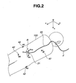
- FIG 2 is a view showing four body surface detection coils mounted on sample points of a subject.
- FIG 3 is a view conceptually showing reference image data stored in a reference image storage portion.
- FIG. 4 is a view showing a configuration of a voxel space.
- a medical guiding system 1 of the present embodiment is a system for performing a guide to support diagnosis operation by an ultrasound endoscope 2 as a medical instrument.
- the medical guiding system 1 of the present embodiment includes the ultrasound endoscope 2, an ultrasound observation apparatus 3, a position/orientation calculation apparatus 4, an image processing apparatus 5, a display apparatus 8, an optical observation apparatus 10, and an input apparatus 11.
- the apparatuses are connected with each other by wired or wireless communication means.
- the medical guiding system 1 is connected to a network 14 provided outside of the medical guiding system 1, which uses an optical fiber, an electrical cable, or wireless communication and the like.
- the network 14 is connected with an X-ray three-dimensional helical CT apparatus (X-ray three-dimensional computed tomography system) 16, a three-dimensional MRI apparatus (three-dimensional magnetic resonance imaging system) 15, and an external storage apparatus 17.
- the medical guiding system 1 is capable of transmitting and receiving data to and from the three-dimensional MRI apparatus 15, the X-ray three-dimensional helical CT apparatus 16, and the external storage apparatus 17, via the network 14.
- the ultrasound endoscope 2 as a medical instrument includes: a rigid portion 21 configured of a rigid material such as stainless steel and disposed at a distal end of an insertion portion to be inserted into a body inside such as an esophagus, a stomach, and a duodenum; a long flexible portion 22 configured of a flexible material and disposed on a proximal end side of the rigid portion 21; and an operation portion 23 configured of a rigid material and disposed on a proximal end side of the flexible portion 22.
- An operator grasps the operation portion 23 to operate the ultrasound endoscope 2.
- the ultrasound endoscope 2 is electrically connected to the ultrasound observation apparatus 3, the optical observation apparatus 10, and the position/orientation calculation apparatus 4 via a connector not shown.
- the rigid portion 21 includes an image pickup apparatus 27, an ultrasound transducer array 31, and an image position/orientation detection coil 44.
- the image pickup apparatus 27 includes: a CCD (Charge Coupled Device) 26 as an image pickup device; a lens 25 for forming an image of a subject on a light-receiving surface of the CCD 26; and the like, and serves as an apparatus for optically picking up an image of inside of the body through an optical observation window 24 made of glass.
- the rigid portion 21 is provided with an illumination apparatus, not shown, for irradiating illumination light in a field of view direction of the image pickup apparatus 27.
- the image pickup apparatus 27 acquires an optical image of the body inside illuminated by the illumination apparatus to output the acquired image as a CCD signal to the optical observation apparatus 10.
- the ultrasound transducer array 31 is a so-called electronic radial scan ultrasound transducer array and configured of a plurality of ultrasound transducers annularly disposed around an insertion axis along an insertion direction of the rigid portion 21 into the body.
- the ultrasound transducer array 31 transmits and receives an ultrasound beam while scanning in a radiation direction at a predetermined time interval on a plane orthogonal to the insertion axis to acquire an echo signal required for acquiring an ultrasound tomographic image, and outputs the acquired echo signal to the ultrasound observation apparatus 3.
- the ultrasound transducer array 31 is electrically connected to the ultrasound observation apparatus 3.
- the ultrasound observation apparatus 3 controls intensity, angle, focus, and the like of the ultrasound beam transmitted by the ultrasound transducer array 31, and also generates ultrasound tomographic image data on a scanning surface based on the echo signal acquired by the ultrasound transducer array 31 and outputs the generated ultrasound tomographic image data.
- orthogonal coordinate axes O-xyz a coordinate system fixed in a real space
- the position of the orthogonal coordinate axes O-xyz is fixed with respect to an examination table on which a subject 100 lies at the time of ultrasound diagnosis.
- a plane to be scanned by the ultrasound transducer array 31 is called as a radial scanning surface SP.
- orthonormal bases (unit vectors of the respective directions) V, V3, and V12 fixed to the rigid portion 21 are defined as shown in FIG. 1 . That is, in a case where the base vector V is assumed to be parallel to an insertion axis direction of the rigid portion 21, in other words, a normal direction vector of the radial scanning surface SP, and a predetermined scan direction of the ultrasound transducer array 31 is assumed to be the twelve o'clock direction, the base vector to orient in the three o'clock direction is defined as V3, and the base vector to orient in the twelve o'clock direction is defined as V12.
- a scanning range by the ultrasound transducer array 31 on the surface to be scanned by the ultrasound transducer array is referred to as an image scan range R of ultrasound tomographic image data.
- the image position/orientation detection coil 44 is disposed in the rigid portion 21 so as to be located in the vicinity of the center of the circular ultrasound transducer array 31 with the positional relationship with respect to the ultrasound transducer array 31 fixed.
- the image position/orientation detection coil 44 includes integrally formed two coils respectively wound around the axes parallel to the base vectors V and V3.
- the center of the image position/orientation detection coil 44 is defined as a position O". Note that, in FIG. 1 , the image position/orientation detection coil 44 is shown apart from the center of the ultrasound transducer array 31 for the convenience of description.
- the position O" of the image position/orientation detection coil 44 generally coincides with a scanning center position of the ultrasound transducer array 31, and indicates a center position of the image scan range R of ultrasound tomographic image data in the present embodiment.
- the base vectors V, V3, and V12 indicate an orientation of ultrasound tomographic image data.
- the position/orientation calculation apparatus 4 as a detection portion is connected to the image position/orientation detection coil 44 disposed in the rigid portion 21 of the ultrasound endoscope 2 via an A/D conversion apparatus 46 and is also electrically connected to a transmission antenna 41.
- the position/orientation calculation apparatus 4 is connected to body surface detection coils 42 via an A/D conversion apparatus 45.
- the position/orientation calculation apparatus 4 is electrically connected to an image processing apparatus 5 via a cable of the RS-232C standard, for example.
- the transmission antenna 41 includes a plurality of magnetic field generation coils of different winding axes orientation, not shown, and generates an alternating magnetic field in response to an output from the position/orientation calculation apparatus 4.
- the transmission antenna 41 is arranged with the position thereof being fixed in a real space.
- the transmission antenna 41 is arranged such that the position thereof is fixed with respect to the examination table on which the subject 100 lies at the time of ultrasound diagnosis. That is, in the present embodiment, the position of the transmission antenna 41 is fixed on the orthogonal coordinate axes O-xyz.
- the A/D conversion apparatuses 45, 46 include an amplifier, not shown, for amplifying an inputted signal, and an analog-digital conversion circuit, not shown, for sampling the amplified signal to convert the signal into digital data.
- the image position/orientation detection coil 44 disposed in the rigid portion 21 of the ultrasound endoscope 2 detects the alternating magnetic field generated by the transmission antenna 41 and converts the detected alternating magnetic field into an position electric signal to output the position electric signal to the A/D conversion apparatus 46.
- the plurality of body surface detection coils 42 respectively include coils for detecting the alternating magnetic field generated by the transmission antenna 41 and convert the alternating magnetic field detected by the coils into a position electric signals to output the position electric signals to the A/D conversion apparatus 45.
- the position/orientation calculation apparatus 4 calculates the respective positions and the orientations of the image position/orientation detection coil 44 and the plurality of body surface detection coils 42 with respect to the transmission antenna 41, based on the position electric signals respectively outputted from the image position/orientation detection coil 44 and the body surface detection coils 42 and converted into digital data by the A/D conversion apparatuses 45, 46.
- the position/orientation calculation apparatus 4 calculates the center position O" of the image position/orientation detection coil 44 and the base vectors V and V3 on the orthogonal coordinate axes O-xyz, based on the position electric signal outputted from the image position/orientation detection coil 44 composed of two coils respectively wound around axes parallel to the base vectors V and V3, to output the information on the center position and base vectors to the image processing apparatus 5.
- the position/orientation calculation apparatus 4 calculates the positions and orientations of the body surface detection coils 42 on the orthogonal coordinate axes O-xyz, based on the position electric signals outputted from the body surface detection coils 42, to output the information on the positions and orientations to the image processing apparatus 5.
- four body surface detection coils 42 are mounted and fixed in the vicinity of four characteristic points on the body surface of the subject 100 (hereinafter, characteristic points on the body surface of the subject 100 are simply referred as sample points) by a tape, a belt, a band, an adhesive, negative pressure absorption, or the like.
- sample points A1 to A4 are defined as follows in the present embodiment. That is, the sample point A1 is defined as “xiphoid process”, the sample point A2 as “left anterior superior iliac spine” on the left side of the pelvis, the sample point A3 as “right anterior superior iliac spine” on the right side of the pelvis, and the sample point A4 as "spinous process of vertebral body” in the middle of the left and right anterior superior iliac spines on the spine (see FIG. 2 ).
- the four sample points A1 to A4 are not limited to those shown in the present embodiment, and appropriately changed depending on a configuration of a medical instrument to be used or on a region with respect to which the medical instrument is used.
- the four sample points A1 to A4 are characteristic points on the skeleton of the subject 100 and the positions thereof can be specified by the operator's palpation.
- the calculation of the position O" of the image position/orientation detection coil 44 and the base vectors V, V3 and the calculation of the positions and the orientations of the four body surface detection coils 42 are performed by the position/orientation calculation apparatus 4 synchronously with the timing of acquiring ultrasound tomographic image data by the ultrasound observation apparatus 3.
- the x-, y- and z-coordinate values of the position O" of the image position/orientation detection coil 44 are referred to as "image position/orientation detection coil position/orientation data".
- body surface detection coil position data the x-, y- and z-coordinate values of each of the four body surface detection coils 42 on the orthogonal coordinate axes O-xyz are referred to as "body surface detection coil position data”.
- the data acquired by combining "the image position/orientation detection coil position/orientation data" and the “body surface detection coil position data” is only referred to as "position/orientation data”.
- the image processing apparatus 5 includes a communication circuit 51, a reference image storage portion 52, an image scan region storage portion 53, a cine memory 54, a tomographic-image-for-saving storage portion 55, a three-dimensional guide image creation circuit 65, a mixing circuit 67, a display circuit 68, and a control circuit 60.
- the control circuit 60 as a control portion includes an arithmetic device, a storage device, an input/output device, and the like, and controls the action of the image processing apparatus 5.
- the control circuit 60 is electrically connected to the potions or circuits in the image processing apparatus 5 via signal lines not shown.
- the control circuit 60 also controls the actions of the ultrasound observation apparatus 3 and the position/orientation calculation apparatus 4.
- the control circuit 60 is electrically connected with the input apparatus 11 as an instruction portion.
- the input apparatus 11 of the present embodiment is composed of a keyboard 12 and a mouse 13.
- the control circuit 60 controls the action of the medical guiding system 1 based on an instruction from an operator inputted through the input apparatus 11.
- the keyboard 12 is provided with a group of keys including a tomographic image one-sheet saving key 12a, a tomographic image successive saving key 12b, and a scan start/termination key 12c.
- the input apparatus 11 is configured of the keyboard 12 and the mouse 13 in the present embodiment. However, this is one example of the input apparatus, and the input apparatus 11 is not limited to the configuration in the present embodiment.
- the input apparatus 11 may be configured of a pointing device such as a trackball and a touch panel, or a switch such as a push switch and rotary switch, for example.
- the input apparatus 11 may be such one that the operator can input an operation instruction by voice or gesture.
- the reference image storage portion 52 is configured for example of a flash memory, a hard disk drive, a tape drive, and the like that are capable of storing a large volume of data.
- the reference image storage portion 52 stores a group of reference image data GRD as information on anatomical three-dimensional image of a human body.
- the group of reference image data GRD is acquired such that the data of human body tomographic image acquired from a predetermined human body by the X-ray three-dimensional helical CT apparatus 16, the three-dimensional MRI apparatus 15, or the like, and stored in an external storage apparatus 17 is inputted to the image processing apparatus 5 via the network 14.
- the group of reference image data GRD is data composed of collection of tomographic images RD of a square region with a side of several tens of centimeters of the cross section which is essentially perpendicular to the body axis (linear axis passing through from the head to the feet).
- the tomographic images RD are acquired at a pitch of 0.5 millimeters to several millimeters along the body axis, for example.
- the lower direction when facing the figure is the dorsal direction of the human body, and the depth direction from the front of the figure is the head direction of the human body.
- the group of reference image data GRD may be acquired from the subject 100 himself/herself, or from a different one or a plurality of human bodies.
- the group of reference image data GRD may be acquired from different human bodies in advance for each condition such as physical features of the human body including body height or body size, and sex.
- the group of reference image data GRD may be directly inputted to the image processing apparatus 5 from the X-ray three-dimensional helical CT apparatus 16 or the three-dimensional MRI apparatus 15 via the network 14 to be stored in the reference image storage portion 52.
- orthogonal coordinate axes O'-x'y'z' fixed with respect to the group of reference image data GRD are defined.
- an origin O' is defined at lower left of the reference image data RD closest to the feet
- the x' axis and the y' axis are defined to be parallel to the lateral side and the longitudinal side, respectively. That is, the z' axis is parallel to the body axis.
- the group of reference image data GRD is configured of a plurality of tomographic images RD of the abdominal region of the human body that are acquired by the X-ray three-dimensional helical CT apparatus 16.
- blood vessels 111 such as an aorta are displayed at a high luminance
- organs such as a pancreas 110 which contain a large number of peripheral arteries are displayed at a medium luminance
- a duodenum 112 and the like are displayed at a low luminance.
- the three-dimensional guide image creation circuit 65 includes an arithmetic device, an extraction circuit, a volume memory, and the like, for fast three-dimensional image processing.
- the volume memory is capable of storing a large volume of data.
- a voxel space is assigned to at least a part of the storage region of the volume memory.
- the voxel space is composed of memory cells (hereinafter referred to as voxels) having addresses corresponding to the orthogonal coordinate axes O'-x'y'z' set for the group of reference image data GRD, as schematically shown in FIG. 4 .
- the extraction circuit extracts data of an organ of interest as a predetermined organ of a human body from the group of reference image data GRD stored in the reference image storage portion 52 to write the data in the voxel space in the volume memory as extracted data.
- the extracted data configures the three-dimensional model image of the organ of interest in the voxel space.
- the three-dimensional guide image creation circuit 65 calculates index data, as three-dimensional image data expressing in the voxel space the position and orientation of the image scan range R of the ultrasound tomographic image data in the real space, by a known coordinate transformation and the like based on the position/orientation data and the like, to further create synthetic data by synthesizing the index data and the extracted data.
- the index data is image data configured of at least one of an ultrasound tomographic image marker indicating the image scan range R of the latest ultrasound tomographic image data on the orthogonal coordinate axes O'-x'y'z' and an image scan history marker indicating a region where an ultrasound tomographic image data has been acquired on the orthogonal coordinate axes O'-x'y'z' in the past.
- the three-dimensional guide image creation circuit 65 reads out synthetic data from the voxel space in the volume memory to executes a known three-dimensional image processing such as hidden surface removal, shading, and coordinate transformation for changing the viewpoint, and creates the three-dimensional guide image data.
- a known three-dimensional image processing such as hidden surface removal, shading, and coordinate transformation for changing the viewpoint
- the mixing circuit 67 generates mixed data by synthesizing the ultrasound tomographic image data outputted from the ultrasound observation apparatus 3 and the three-dimensional guide image data outputted from the three-dimensional guide image creation circuit 65.
- the display circuit 68 converts the mixed data outputted from the mixing circuit 67 into a video signal to output the video signal to the display apparatus 8.
- the display circuit 68 also has a configuration to convert the optical image data outputted from the optical observation apparatus 10 into a video signal and output the video signal to the display apparatus 8.
- the display apparatus 8 includes an image display portion such as a cathode ray tube monitor, or a liquid crystal monitor, and has a configuration to display an image based on the video signal on the image display portion.
- an image display portion such as a cathode ray tube monitor, or a liquid crystal monitor
- the cine memory 54 is configured of a memory serving as a high-speed readable/writable storage device.
- the cine memory 54 stores a series of plurality of ultrasound tomographic image data acquired by successive radial scans by the ultrasound transducer array 31, a plurality of position/orientation data calculated in synchronization with the respective acquisitions of plurality of ultrasound tomographic image data, and serial numbers attached to the respective plurality of ultrasound tomographic image data, in association with one another.
- the image scan region storage portion 53 is configured of a memory serving as a high-speed readable/writable storage device.
- the tomographic-image-for-saving storage portion 55 is configured for example of a flash memory, a hard disk drive, a tape drive, or the like.
- the tomographic-image-for-saving storage portion 55 stores the data instructed to be saved by the operator through the input apparatus 11, among the plurality of ultrasound tomographic image data and the data associated with the plurality of ultrasound tomographic image data that are stored in the cine memory 54.
- the saving instruction from the operator is made by the operator's depression of the tomographic image one-sheet saving key 12a or the tomographic image successive saving key 12b on the keyboard 12 during the scan by the ultrasound transducer array 31 of the ultrasound endoscope 2.
- the tomographic image one-sheet saving key 12a when the tomographic image one-sheet saving key 12a is depressed by the operator, one latest ultrasound tomographic image data at the time and the position/orientation data at the time of acquiring the ultrasound tomographic image data are read out from the cine memory 54 to be stored in the tomographic-image-for-saving storage portion 55 as tomographic-image-for-saving data which is a still image.
- the tomographic image successive saving key 12b when the tomographic image successive saving key 12b is depressed by the operator, all of the ultrasound tomographic image data stored in the cine memory 54 at the time when the tomographic image successive saving key 12b was depressed are read out to be stored in the tomographic-image-for-saving storage portion 55 as the tomographic-image-for-saving data which is a moving image. That is, when the tomographic image successive saving key 12b is depressed by the operator, the tomographic-image-for-saving data is the moving image configured of a plurality of ultrasound tomographic image data successively acquired at predetermined time intervals. At the same time, the position/orientation data associated with all of the ultrasound tomographic image data stored in the cine memory 54 are also stored in the tomographic-image-for-saving storage portion 55.
- FIG 5 is a flowchart of a main routine showing an entire action of the medical guiding system.
- FIG. 6 is a flowchart showing a display processing of an ultrasound tomographic image and a three-dimensional guide image.
- FIG. 7 is a table showing one example of image scan region data.
- FIG. 8 is a view describing a three-dimensional guide image.
- FIG. 9 is a view describing mixed data displayed on a display apparatus.
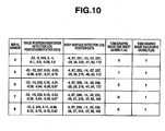
- FIG 10 is a table showing one example of files saved in a tomographic-image-for-saving storage portion.
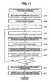
- FIG. 11 is a flowchart showing a creation processing of three-dimensional guide image data.
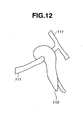
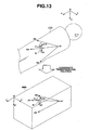
- FIG. 12 is one example of a three-dimensional model image of an organ of interest.
- FIG. 13 is a view describing the concept of coordinate transformation.
- FIG. 14 is a view describing an image scan history reproduced image.
- the control circuit 60 acquires information on the organ of interest indicating the kind of the organ to be diagnosed (step S01).
- the control circuit 60 displays options on the display apparatus 8 to prompt the operator to select an organ of the human body.
- the operator specifies one or a plurality of organs of interest from the options of the organs displayed on the display apparatus 8 through the input apparatus 11, and thereby the information on the organ of interest is inputted to the control circuit 60.
- the pancreas is specified as the organ of interest as described above.
- the selection screen of the organs of interest which is displayed on the display apparatus 8 may display the information on the organs of the human body by a two-dimensional or three-dimensional image on which the operator visually selects the organ of interest.
- the organs of the human body may be displayed as character strings from which the operator selects the organ of interest.
- control circuit 60 sets a plurality of feature points A' in the group of reference image data GRD by an input of instruction by the operator or an automatic calculation, to execute a processing of acquiring the coordinates on the orthogonal coordinate axes O'-x'y'z' of the plurality of feature points A' (step S02).
- the plurality of feature points A' in the group of reference image data GRD anatomically correspond to the plurality of sample points A on the body surface or inside the body of the subject 100.
- the feature points A' are the feature points A1' to A4' respectively corresponding to the sample points A1 to A4. That is, the feature points A1', A2', A3' and A4' are pixels in the group of reference image data GRD corresponding to the xiphoid process, the left anterior superior iliac spine, the right anterior superior iliac spine, and the spinous process of vertebral body, respectively.
- the pixels corresponding to the plurality of feature points A1' to A4' in the group of reference image data GRD are specified by the input from the operator through the input apparatus 11, for example, thereby acquiring and storing the coordinates on the orthogonal coordinate axes O'-x'y'z' of the respective plurality of feature points A1' to A4'.
- control circuit 60 provides a display to prompt the operator to mount the body surface detection coils 42 on the subject 100 on the display apparatus 8 (step S03).
- the operator mounts and fixes the body surface detection coils 42 in the vicinity of sample points on the body surface of the subject 100.
- the four body surface detection coils 42 are respectively mounted by the operator in the vicinity of the sample point A 1 (xiphoid process), the sample point A2 (left anterior superior iliac spine), the sample point A3 (right anterior superior iliac spine), and the sample point A4 (spinous process of vertebral body) of the subject 100.
- the control circuit 60 executes a display processing, to be described in detail later, of the ultrasound tomographic image and the guide image (step S04).
- the operator inserts the rigid portion 21 and the flexible portion 22 of the ultrasound endoscope 2 into the body of the subject 100 and makes diagnosis while referring to the ultrasound tomographic image data and the three-dimensional guide image data displayed on the display apparatus 8.
- the control circuit 60 repeatedly executes the processing in the step S04 until an inspection termination key not shown on the keyboard 12 is depressed by the operator (step S05).
- the control circuit 60 associates image scan region data 70 stored in the image scan region storage portion 53 with the ultrasound tomographic image data stored in the tomographic-image-for-saving storage portion 55, to execute termination processing.
- control circuit 60 stands by until the operator depresses the scan start/termination key 12c on the keyboard 12 to give an instruction to start radial scan (step S11).
- control circuit 60 executes an initial processing for starting radial scan by the ultrasound transducer array 31, and the procedure moves on to the step S12.
- the three-dimensional guide image creation circuit 65 acquires the position/orientation data outputted from the position/orientation calculation apparatus 4 (step S12).
- the position/orientation data is configured of the data of the position O" and the orientation of the image position/orientation detection coil 44 and the data of the respective positions of the four body surface detection coils 42, on the orthogonal coordinate axes O-xyz.
- the three-dimensional guide image creation circuit 65 assigns a serial number to the position/orientation data acquired in the step S12 to store the serial number and the position/orientation data in the image scan region storage portion 53 as the image scan region data 70 (step S13).
- the image scan region data 70 is matrix-shaped data as shown in the table in FIG 7 .
- the column direction of the image scan region data 70 is configured of five kinds of data, that is, "serial number 71 ", "image position/orientation detection coil position/orientation data 72", "body surface detection coil position data 73", “tomographic image one-sheet saving flag 74", and "tomographic image successive saving flag 75".
- the serial number 71 is a natural number not less than 1, and is data such that the first value of which immediately after the start instruction of the radial scan is set to 1, and thereafter every time the step S 13 is executed, the value is incremented by one, like 2, 3, 4, etc. That is, the serial number 71 is a value indicating the data acquisition order.
- the image position/orientation detection coil position/orientation data 72 is the data in which the values of coordinates and coordinate components on the orthogonal coordinate axes O-xyz are described in the following order: the x-, y- and z-coordinate values of the position O" of the image position/orientation detection coil 44; the x-, y- and z-coordinate components of the base vector V; and the x-, y- and z-coordinate components of the base vector V3.
- the body surface detection coil position data 73 is the data in which the respective x-, y- and z-coordinate values on the orthogonal coordinate axes O-xyz of the four body surface detection coils 42 are described.
- the respective x-, y- and z-coordinate values of the body surface detection coils 42 mounted on the sample points A1 to A4 of the subject 100 are described in the order of the sample points A1, A2, A3, and A4.
- the tomographic image one-sheet saving flag 74 and the tomographic image successive saving flag 75 are binary data of 0 or 1, and 0 is written when newly described.
- the three-dimensional guide image creation circuit 65 first reads the largest value of the serial numbers 71 in the image scan region data 70. Then the three-dimensional image creation circuit 65 creates and adds a data row having a new serial number acquired by adding one to the largest serial number 71, and then further writes the latest image position/orientation detection coil position/orientation data 72 and the body surface detection coil position data 73 that are acquired in the immediately preceding step S12, into the data row having the new serial number. In addition, the three-dimensional image creation circuit 65 writes the value 0 as the respective values of the tomographic image one-sheet saving flag 74 and the tomographic image successive saving flag 75, into the data row having the new serial number.
- the three-dimensional guide image creation circuit 65 newly creates a file of the image scan region data 70 in which to write a data row, the serial number 71 of which is 1. Then, the three-dimensional guide image creation circuit 65 writes the latest image position/orientation detection coil position/orientation data 72 and the body surface detection coil position data 73, which are acquired in the immediate preceding step S12, into the data row, the serial number 71 of which is 1. Furthermore, the three-dimensional guide image creation circuit 65 writes the value 0 as the respective values of the tomographic image one-sheet saving flag 74 and the tomographic image successive saving flag 75, into the data row, the serial number of which is 1.
- the mixing circuit 67 acquires the ultrasound tomographic image data outputted from the ultrasound observation apparatus 3 (step S 14).
- the ultrasound tomographic image data is acquired synchronously with the position/orientation data.
- control circuit 60 stores in the cine memory 54 the ultrasound tomographic image data acquired by the mixing circuit 67 in the step S 14, the position/orientation data acquired in the step S12, and the serial number assigned to the position/orientation data in step S 13, in association with one another (step S 15).
- the ultrasound tomographic image data the image position/orientation detection coil position/orientation data, the body surface detection coil position data, and the serial number are stored in association with one another as one set of data, in the cine memory 54.
- step S 15 when no storage capacity for storing new set of data is left in the cine memory 54, the above-described new set of data is stored after one set of data with the smallest serial number is deleted.
- the three-dimensional image creation circuit 65 creates the three-dimensional guide image data as shown in FIG. 8 by a method to be described later in detail, to output the created three-dimensional guide image data to the mixing circuit 67 (step S16).
- the three-dimensional guide image data is three-dimensional image data indicating the positions of the image scan range R of the past and the latest ultrasound tomographic image data with respect to an organ of interest. Note that the viewpoint of the three-dimensional guide image data as the three-dimensional image data can be set at an arbitrary position by an instruction inputted by the operator.
- the mixing circuit 67 creates mixed data for display as shown in FIG. 9 by synthesizing the ultrasound tomographic image data acquired in the step S 14 and the three-dimensional guide image data inputted in the step S16. Then, the display circuit 68 converts the mixed data created by the mixing circuit 67 into a video signal to output the video signal to the display apparatus 8. The display apparatus 8 adjacently displays the ultrasound tomographic image data and the three-dimensional guide image data, based on the video signal (step S 17).
- control circuit 60 determines whether or not the tomographic image one-sheet saving key 12a on the keyboard 12 has been depressed by the operator during the execution of the steps S12 to S 17 (step S 18).
- step S 18 when the control circuit 60 determines that the tomographic image one-sheet saving key 12a has been depressed, the procedure moves on to step S 19. On the other hand, in the step S 18, when the control circuit 60 determines that the tomographic image one-sheet saving key 12a is not depressed, the procedure moves on to step S21.
- the control circuit 60 stores in the tomographic-image-for-saving storage portion 55 the latest data stored in the cine memory 54, i.e, the latest ultrasound tomographic image data, image position/orientation detection coil position/orientation data, and body surface detection coil position data, in association with one another.
- the control circuit 60 rewrites to 1 the value of the tomographic image one-sheet saving flag 74 in the latest data row in the image scan region data 70 stored in the image scan region storage portion 53, to update the image scan region data 70.
- rewriting is performed on the data row in the image scan region data 70, including the value of the serial number corresponding to the ultrasound tomographic image data saved in the tomographic-image-for-saving storage portion 55 in the step S19. Then the procedure moves on to the step S21.
- control circuit 60 determines whether or not the tomographic image successive saving key 12b on the keyboard 12 has been depressed by the operator during the execution of the steps S12 to S 17.
- step S21 when the control circuit 60 determines that the tomographic image successive saving key 12b has been depressed, the procedure moves on to step S22. On the other hand, in the step S21, when the control circuit 60 determines that the tomographic image successive saving key 12b is not depressed, the procedure moves on to step S24.
- the control circuit 60 stores in the tomographic-image-for-saving storage portion 55 all of the data stored in the cine memory 54, i.e, all of the ultrasound tomographic image data, the image position/orientation detection coil position/orientation data, and the body surface detection coil position data, in association with one another.
- step S22 when data of five sheets of ultrasound tomographic images corresponding to the serial number values 4 to 8 and the position/orientation data corresponding to the five sheets of the ultrasound tomographic images are stored in the cine memory 54, all of the data are saved in the tomographic-image-for-saving storage portion 55 by the processing of the step S22.
- one file as shown in FIG. 10 in which the serial numbers and the position/orientation data corresponding to the five sheets of ultrasound tomographic images are described, is saved in the tomographic-image-for-saving storage portion 55.
- the data of the five sheets of ultrasound tomographic images are saved with the same file names as the corresponding serial numbers. That is, the ultrasound tomographic image data are associated with the serial numbers and the position/orientation data by the file names.
- the control circuit 60 rewrites to 1 the value of the tomographic image successive saving flag 75 in the data row corresponding to the ultrasound tomographic image saved in the step S22 in the image scan region data 70 stored in the image scan region storage portion 53, to update the image scan region data 70.
- rewriting is performed on the data row in the image scan region data 70, the data row including the value of the serial number corresponding to the ultrasound tomographic image data saved in the tomographic-image-for-saving storage portion 55 in the step S22. Then the processing moves on to the step S24.
- control circuit 60 determines whether or not the scan start/termination key 12c on the keyboard 12 has been depressed by the operator during the execution of the steps S12 to S23.
- step S24 when the control circuit 60 determines that the scan start/termination key 12c has not been depressed in the step S24, the procedure returns to the step S12 and the above-described processings are repeated.
- the medical guiding system 1 of the present embodiment repeatedly executes the steps S12 to S23 at a predetermined cycle until the scan start/termination key 12c is depressed again, thereby sequentially creating new three-dimensional guide image data, to display in real time the created three-dimensional guide image data together with new ultrasound tomographic image data on the image display portion of the display apparatus 8.
- step S24 when the control circuit 60 determines that the scan start/termination key 12c has been depressed, the procedure moves on to the step S25, and the control circuit 60 outputs a signal for stopping the radial scan by the ultrasound transducer array 31 to the ultrasound observation apparatus 3 to terminate the radial scan, thereby terminating the display processing of the ultrasound tomographic image and the three-dimensional guide image.
- the three-dimensional image creation circuit 65 reads the group of reference image data GRD stored in the reference image storage portion 52 (step S31).
- the three-dimensional image creation circuit 65 extracts the data of the organ of interest from the group of reference image data GRD to write the data in the voxel space in the volume memory as extracted data (step S32).
- the three-dimensional image creation circuit 65 creates the three-dimensional model image displaying only the pancreas 110 as the organ of interest and the blood vessels 111 as shown in FIG. 12 for example, as extracted data, and writes the extracted data in the voxel space.
- the three-dimensional guide image creation circuit 65 defines a variable i to be stored therein, and sets the value of the variable I to 0 (step S33).
- the three-dimensional guide image creation circuit 65 reads the data row, the value of the serial number 71 of which is equal to the variable i, from the image scan region data 70 stored in the image scan region storage portion 53 (step S35).
- the three-dimensional guide image creation circuit 65 calculates the image scan range R of the ultrasound tomographic image data on the orthogonal coordinate axes O-xyz as a real space from a set value of the ultrasound scanning range, that is, the set value of the length of one side of the ultrasound tomographic image data in a square shape, and the image position/orientation detection coil position/orientation data among the data read in the step S35 (step S36).
- the three-dimensional guide image creation circuit 65 calculates the coordinates on the orthogonal coordinate axes O-xyz, of the four vertices R1 to R4 of the image scan range R of the ultrasound tomographic image in a square shape, based on the image position/orientation detection coil position/orientation data, that is, the position O" of the image position/orientation detection coil 44 and the base vectors V and V3 indicating the orientation of the image position/orientation detection coil 44.
- the base vector V12 is calculated by calculating the outer product of the base vectors V and V3. Then, assuming that the length of one side of the ultrasound tomographic image data is a, the coordinates of the first vertex R1 are calculated based on the equation O" + a/2 • (V12) + a/2 • (V3), the coordinates of the second vertex R2 based on the equation O"- a/2 • (V12) + a/2 • (V3), the coordinates of the third vertex R3 based on the equation O" + a/2 • (V12) - a/2 • (V3), and the coordinates of the fourth vertex R4 based on the equation O"-a/2 • (V12) - a/2 • (V3).
- the three-dimensional guide image creation circuit 65 calculates a coordinate transformation equations for mapping the coordinates on the orthogonal coordinate axes O-xyz to the coordinates on the orthogonal coordinate axes O'-x'y'z', based on the body surface detection coil position data among the data read in the step S35, that is, the coordinates on the orthogonal coordinate axes O-xyz of the plurality of body surface detection coils 42, and the coordinates on the orthogonal coordinate axes O'-x'y'z' of the plurality of feature points A' in the group of reference image data GRD, which were acquired in the step S02. Then, as conceptually shown in FIG.
- the three-dimensional guide image creation circuit 65 maps the image scan range R of the ultrasound tomographic image data on the orthogonal coordinate axes O-xyz, which was calculated in the step S36, on the orthogonal coordinate axes O'-x'y'z' (step S37).
- the image scan range R mapped on the orthogonal coordinate axes O'-x'y'z' is referred to as a mapped image scan range R'.
- the mapped image scan range R' is a quadrilateral planar region defined by the four points R1' to R4' acquired by mapping the four vetices R1 to R4 calculated in the step S36 on the orthogonal coordinate axes O'-x'y'z' using the coordinate transformation equations.
- the three-dimensional guide image creation circuit 65 creates image scan history markers 80 as the index data indicating the region corresponding to the mapped image scan range R' on the orthogonal coordinate axes O'-x'y'z' in the step S37, and writes the image scan history markers 80 in the voxel space in the volume memory to create synthetic data (step S38).
- the image scan history markers 80 are three-dimensional image data each expressing a translucent quadrilateral plane having four points R1' to R4' calculated in the step S37 as vertices, as shown in FIG. 8 .
- the synthetic data in the voxel space is created such that the image scan history markers 80 are superimposed on the extracted data of the organ of interest, as shown in FIG. 8 .
- the three-dimensional guide image creation circuit 65 draws the image scan history markers 80 such that the line types of the border lines indicating the perimeters of the quadrilateral image scan history markers 80 are changed depending on the values of "the tomographic image one-sheet saving flag 74" and "the tomographic image successive saving flag 75" among the data read in the step S35.
- the line type of the border lines is a dotted line (the reference numeral 81 in the FIG. 8 ), when both of the values of the tomographic image one-sheet saving flag 74 and the tomographic image successive saving flag 75 are 1, the line type of the border lines is a dashed line (the reference numeral 82 in the FIG. 8 ), when the value of the tomographic image one-sheet saving flag 74 is 0 and the value of the tomographic image successive saving flag 75 is 1, the line type of the border lines is a chain line (the reference numeral 83 in FIG. 8 ), and when the value of the tomographic image one-sheet saving flag 74 is 1 and the value of the tomographic image successive saving flag 75 is 0, the line type of the border lines is a solid line (the reference numeral 84 in FIG. 8 ).
- the image scan history markers 80 are displayed in different ways depending on the corresponding values of the tomographic image one-sheet saving flag 74 and the tomographic image successive saving flag 75, and the markers are not limited to the aspect of display differentiated by the line types as in the present embodiment.
- the image scan history markers 80 may be displayed in different colors depending on the corresponding values of the tomographic image one-sheet saving flag 74 and the tomographic image successive saving flag 75, or differentiated by brightness difference or cyclical blinking, for example.
- the three-dimensional guide image creation circuit 65 determines a magnitude relation between the largest value N of the serial number 71 in the image scan region data 70 stored in the image scan region storage portion 53 and the variable i (step S39).
- step S39 when the variable i is smaller than the largest value N of the serial number 71, the procedure returns to the step S34 and the processings in steps S34 to S38 are repeated. That is, when there are plurality of data rows described in the image scan region data 70, the processings in the steps S34 to S38 are repeated on all of the data rows, and thereby a plurality of image scan history markers 80 as shown in FIG. 8 are written in the voxel space in the volume memory as index data.
- step S39 when the variable i is equal to the largest value N of the serial number 71, the procedure moves on to step S40.
- the three-dimensional guide image creation circuit 65 changes the image scan history marker 80 created last, to highlight the marker as an image scan region marker 85.
- the image scan history marker 80 created last is the image scan history marker 80 corresponding to the data row, the serial number 71 of which in the image scan region data 70 is the largest value N.
- the three-dimensional guide image creation circuit 65 changes the line type of the border line indicating the perimeter of the image scan region marker 85 to a thick line, to write the image scan region marker 85 in the voxel space.
- the image scan region marker 85 created in the step S40 is the index indicating the mapped image scan range R' on the orthogonal coordinate axes O'-x'y'z' of the latest ultrasound tomographic image data.
- the three-dimensional guide image creation circuit 65 creates a distal end direction marker 86 and a twelve o'clock direction marker 87 as indexes to indicate the orientation of the mapped image scan range R' on the orthogonal coordinate axes O'-x'y'z' of the latest ultrasound tomographic image data, and writes the markers in the voxel space in the volume memory (step S41).
- the distal end direction marker 86 is an arrow-shaped (pyramid-shaped) three-dimensional object which is perpendicular to the image scan region marker 85 from the barycentric position of the image scan region marker 85 and extends in the insertion direction of the rigid portion 21 on the orthogonal coordinate axes O'-x'y'z'.
- the twelve o'clock direction marker 87 is an arrow-shaped image to indicate the twelve o'clock direction of the radial scan on the orthogonal coordinate axes O'-x'y'z', which is drawn on the same plane as the image scan region marker 85.
- the three-dimensional guide image creation circuit 65 calculates a coordinate transformation equation for mapping the coordinates on the orthogonal coordinate axes O-xyz to the coordinates on the orthogonal coordinate axes O'-x'y'z', based on the body surface detection coil position data in the data row, the serial number 71 of which in the image scan region data 70 is the largest value N, and the coordinates on the orthogonal coordinate axes O'-x'y'z' of the plurality of feature points A' in the group of reference image data GRD.
- the three-dimensional guide image creation circuit 65 calculates the base vectors V' and V3' by mapping the base vectors V and V3 on the orthogonal coordinate axes O'-x'y'z', in the data row, the serial number 71 of which in the image scan region data 70 is the largest value N. Then, the three-dimensional guide image creation circuit 65 calculates the base vector V 12' by calculating the outer product of the base vectors V and V3.
- the three-dimensional guide image creation circuit 65 creates the distal end direction marker 86 and the twelve o'clock direction marker 87 which are the arrow-shaped image data indicating the directions of the base vectors V' and V12' on the orthogonal coordinate axes O'-x'y'z', respectively, to write the markers in the voxel space in the volume memory.
- the image scan region marker 85, the distal end direction marker 86, and the twelve o'clock direction marker 87 configure the ultrasound tomographic image marker indicating the image scan range R of the latest ultrasound tomographic image data on the orthogonal coordinate axes O'-x'y'z' in the present embodiment.
- the three-dimensional guide image creation circuit 65 creates three-dimensional guide image data.
- the medical guiding system of the present embodiment 1 is capable of performing not only an action of displaying by changing in real time the current image scan position and the history of the past image scan position of the ultrasound tomographic image with respect to the organ of the subject as the three-dimensional guide images, at the time of making diagnosis with the above-described ultrasound diagnostic apparatus, but also an action of reproducing and displaying the history of the image scan position of the ultrasound tomographic image so that the operator can perform observation while confirming the ultrasound tomographic image and the position where the ultrasound tomographic image was scanned at the same time, after the diagnosis.
- the image processing apparatus 5 as an ultrasound tomographic image reproducing portion creates an image scan history reproduced image as shown in FIG. 14 , to display the created image scan history reproduced image on the image display portion of the display apparatus 8.
- the image scan history reproduced image is an image in which the ultrasound tomographic image data is displayed on the right side of the image display portion of the display apparatus 8 and the position of the currently displayed ultrasound tomographic image data with respect to the organ of interest is displayed on the left side, in the present embodiment.
- the control circuit 60 reads a predetermined one sheet of ultrasound tomographic image data specified by the operator through the input apparatus 11 among all of the ultrasound tomographic image data stored in the tomographic-image-for-saving storage portion 55.
- the three-dimensional guide image creation circuit 65 executes similar processings as those in the above-described steps S31 to S39, to create image scan history image data on which the three-dimensional model image of the organ of interest and a plurality of image scan history markers 80 based on all of the data rows recorded in the image scan region data 70 stored in the image scan region storage portion 53 are superimposed on each other. That is, the image scan history markers 80 are three-dimensional image data indicating the positions and the orientations of the image scan regions of all of the ultrasound tomographic image data acquired during the diagnosis.
- the three-dimensional guide image creation circuit 65 changes the line type of the border line indicating the perimeter of the image scan history marker 80 corresponding to the predetermined one sheet of the ultrasound tomographic image data specified by the operator, among the plurality of image scan history markers 80, to a thick line to highlight the image scan history marker (the reference numeral 89 in FIG. 14 ). Furthermore, the three-dimensional guide image creation circuit 65 creates the distal end direction marker 86 and the twelve o'clock direction marker 87 that indicate the orientation of the predetermined one sheet of the ultrasound tomographic image data specified by the operator.
- the mixing circuit 67 generates mixed data in which the predetermined one sheet of ultrasound tomographic image data read by the control circuit 60 and the image scan history image data created by the three-dimensional guide image creation circuit 65 are synthesized as shown in FIG. 14 and outputs the generated mixed data. Then, the display apparatus 8 displays the image scan history reproduced image based on the mixed data on the image display portion.
- the three-dimensional guide image creation circuit 65 changes the image scan history marker 80 to be highlighted and to which the distal end direction marker 86 and the twelve o'clock direction marker 87 are to be added, to the one corresponding to the ultrasound tomographic image data to be newly displayed by the switching.
- the ultrasound tomographic image data are sequentially switched and displayed on the image display portion of the display apparatus 8 in the order of the times when the data were saved during inspection.
- the image scan history marker 80 to be highlighted and to which the distal end direction marker 86 and the twelve o'clock direction marker 87 are to be added in the image scan history reproduced image is also switched and displayed.
- the moving image is reproduced and displayed on the image display portion of the display apparatus 8 when a reproducing key, not shown, is depressed by the operator.
- the aspect of the image scan history markers 80 displayed in the image scan history reproduced image is not limited to one in which all of the image scan history markers 80 corresponding to all of the ultrasound tomographic image data acquired during inspection are displayed, but the image scan history marker 80 corresponding only to the data row in which at least one of the values of the tomographic image one-sheet saving flag 74 and the tomographic image successive saving flag 75 in the image scan region data 70 stored in the image scan region storage portion 53 is 1, for example.
- the load of processings required for display can be reduced.
- visibility of the image scan history marker 80 is improved, thereby enabling the operator to easily grasp the positional relationship between the organ of interest and the image scan history marker 80.
- the image scan history markers 80 indicating a history of the regions where the ultrasound tomographic image data were acquired in the past are displayed superimposed on the three-dimensional model image of the organ of interest.
- using the medical guiding system 1 of the present embodiment can make it easier for the operator to visually recognize the positional relationship of the past image scan regions with respect to the organ of interest, that is, the history of the regions where ultrasound diagnosis has been already made with respect to the organ of interest. Therefore, the operator can surely make an ultrasound diagnosis with respect to the organ of interest without oversight.
- using the medical guiding system 1 of the present embodiment can make it easier for the operator to visually recognize the history of the regions where ultrasound diagnosis has already been made with respect to the organ of interest, thereby eliminating repeated scan on the same region and shortening the diagnosis time. As a result, the burdens on the operator and the subject are reduced.
- the image scan positions of the tomographic-image-for-saving data are also displayed superimposed on the three-dimensional model image of the organ of interest as the image scan history markers 80.
- using the medical guiding system 1 of the present embodiment can make it easier for the operator to visually check the image scan positions of the saved ultrasound tomographic image data with respect to the organ of interest. As a result, the operator can surely remember to save the ultrasound tomographic image data required for diagnosis.
- the regions where the ultrasound diagnosis has been performed, the tomographic-image-for-saving data, and the image scan positions of the tomographic-image-for-saving data are saved, and reproduced and displayed as the image scan history reproduced images after diagnosis. Therefore, the operator confirms these data as the image scan history reproduced images after diagnosis, thereby enabling the work such as sorting the medical records to be performed more easily and in a shorter time.
- the regions where the ultrasound diagnosis has been performed, the tomographic-image-for-saving data, and the image scan positions of the tomographic-image-for-saving data are saved, and reproduced and displayed as the image scan history reproduced images after diagnosis. Therefore, by using the medical guiding system 1 of the present embodiment, the operator can confirm the image scan history reproduced images after diagnosis to compare the ultrasound tomographic image data with the image scan positions of the ultrasound tomographic data with respect to the organ of interest, thereby easily confirming a position of a legion such as a tumor three-dimensionally and drawing up a precise operation plan.
- the position/orientation data and the ultrasound tomographic image data are associated with each other by the serial numbers and the file names.
- the method of associating the data is not limited to this.
- the position/orientation data and the ultrasound tomographic image data may be associated with each other by data of the time when each of the data was acquired and generated.
- the length a of one side of the image scan range R of the ultrasound tomographic image data is assumed to be a fixed value. That is, the shape and area of the image scan range R are assumed to be fixed.
- the present invention is not limited to this aspect.
- the scan range information is stored as the image scan region data 70 in association with the ultrasound tomographic image data, and the image scan history marker 80 is displayed in a size and shape corresponding to the change in the intensity and the scan range of the ultrasound beam.
- the electronic radial scan ultrasound endoscope 2 is used as the ultrasound diagnostic apparatus which is the medical instrument.
- the aspect of the ultrasound diagnostic apparatus is not limited to the present embodiment.
- the ultrasound diagnostic apparatus may be a mechanical scan ultrasound endoscope or an electronic convex scan ultrasound endoscope including a group of ultrasound transducers provided in a sector shape.
- the present invention is not limited by the ultrasound scanning method.
- the ultrasound diagnostic apparatus may be an ultrasound probe without an optical observation window or a capsule ultrasound sonde.
- the ultrasound diagnostic apparatus may be a so-called extracorporeal ultrasound diagnostic apparatus which performs ultrasound scan from the body surface toward inside of the body of the subject.
- the transmission antenna 41 and the reception coil are used as the position detection means to detect the position and orientation based on the magnetic field, however, the transmission and reception relationship of the magnetic field may be reversed, and the position and orientation may be detected using acceleration or other means instead of the magnetic field.
- the image position/orientation detection coil 44 is disposed in the vicinity of the center of the circular ultrasound transducer array 31, the positional relationship of the two is not limited to such aspect. That is, in order to evaluate the coordinates and the orientation of the scan center of the ultrasound tomographic image from the position and the orientation of the image position/orientation detection coil 44, the relative position between the ultrasound transducer array 31 and the image position/orientation detection coil 44 has only to be fixed.
- a plurality of sheets of two-dimensional CT images and two-dimensional MRI images scanned by the X-ray three-dimensional helical CT apparatus 16 and the three-dimensional MRI apparatus 15 are used as the data configuring the group of reference image data GRD.
- three-dimensional image data previously acquired using another modality such as PET (Positoron Emission Tomography), for example, may be used as the group of reference image data GRD.
- the group of reference image data GRD may be configured of the three-dimensional image data previously acquired by a so-called extracorporeal ultrasound diagnostic apparatus, which performs ultrasound scan from outside the body.
- the four body surface detection coils 42 wound in one axis direction are mounted to the subject 100 to acquire the position/orientation data of the four sample points A1 to A4.
- the position/orientation data of four sample points A 1 to A4 may be acquired by having the subject 100 lie in a left lateral position, thereafter sequentially bringing one body surface detection coil into contact with the four sample points A1 to A4.
- the position/orientation calculation apparatus 4 calculates only the positions thereof in the present embodiment.
- the position/orientation calculation apparatus 4 may calculate the direction of the winding axis of the body surface detection coils 42 instead of the positions thereof.
- the position/orientation calculation apparatus 4 may calculate both the positions and direction of the winding axis of the body surface detection coils 42. With the increased degree of freedom of calculation with respect to one body surface detection coil 42 by the position/orientation calculation apparatus 4, the number of the body surface detection coils 42 can be decreased, thereby reducing the burdens of the operator and the subject 100 when the body surface detection coils 42 are mounted to the subject 100 and during the diagnosis by the ultrasound endoscope 2.
- the sample points are assumed to be the xiphoid process, the left anterior superior iliac spine, the right anterior superior iliac spine, and the spinous process of vertebral body.
- the sample points are not limited to this example and may be feature points on the thoracic surface or thoracic cavity or other examples.
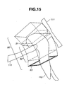
- FIG. 15 is a view describing a three-dimensional guide image of the present embodiment.
- the present embodiment differs from the first embodiment only in the display aspect of the image scan history marker, but other configurations are the same. Therefore, only the different point is described below.
- a medical guiding system of the present embodiment displays an image scan history marker 90 for indicating the region where the ultrasound scan has been performed is displayed in the three-dimensional guide image data, as a moving locus of the image scan range R of the ultrasound tomographic image data, as shown in FIG. 15 .
- the image scan history marker 90 of the present embodiment has a three-dimensional shape formed by connecting the contours of the image scan history markers 80 which are a plurality of quadrilateral planes formed by the similar method as that in the first embodiment.
- the image scan history marker 90 of the present embodiment is expressed by a wireframe as a three-dimensional contour indicating the moving locus of the image scan range R of the ultrasound tomographic image data.
- the wireframe of the image scan history marker 90 of the present embodiment and the region inside of the wireframe are colored by pixels of different transmissivity and color according to the change of the values of the tomographic image one-sheet saving flag 74 and the tomographic image successive saving flag 75.
- the image scan history marker 90 of the present embodiment distinctly expresses the following by the change in color: the moving locus of the image scan range R of the ultrasound tomographic image data; the region for which the one sheet of the ultrasound tomographic image has been saved; and the region for which the ultrasound tomographic image data have been successively saved.
- the wireframe of the image scan history marker 90 and the region inside of the wireframe are expressed in a semi-transparent white color.
- the wireframe of the image scan history marker 90 and the region inside of the wireframe are expressed in green color (the reference numeral 91 in FIG. 15 ).
- the wireframe of the image scan history marker 90 and the region inside of the wireframe is expressed in blue color (the reference numeral 92 in FIG. 15 ).
- the region corresponding to the position of the image scan range R of the latest ultrasound tomographic image data is expressed as a quadrilateral frame highlighted by thick black lines (the reference numeral 93 in FIG. 15 ).
- the transmissivity and the luminance of the image scan history marker 90 can be changed to an arbitrary transmissivity and luminance by the operator's operation so that the operator can easily grasp the positional relationship between the marker and the three-dimensional model image of the organ of interest.
- the above-described medical guiding system of the present embodiment not only has the same effect as that in the first embodiment, but also has a simpler expression of the image scan history marker in the three-dimensional guide image data, so that the operator can intuitively and quickly realize the history of the region where the ultrasound diagnosis has been already performed with respect to the organ of interest.
- FIG. 16 is a view describing the three-dimensional guide image of the present embodiment.
- the present embodiment differs from the second embodiment only in the display aspect of the image scan history marker, but other configurations are the same. Therefore, only the different point is described below.
- a medical guiding system of the present embodiment displays an image scan history marker 90a for indicating the region where the ultrasound scan has been performed, as the moving locus of the image scan range R of the ultrasound tomographic image data in the three-dimensional guide image data.
- the image scan history marker 90a of the present embodiment is expressed by a wireframe as a three-dimensional contour indicating the moving locus of the image scan range R of the ultrasound tomographic image data, as in the second embodiment.
- the wireframe of the image scan history marker 90a and the region inside of the wireframe are colored by the pixels of different transmissivity and color according to the change of the values of the tomographic image one-sheet saving flag 74 and the tomographic image successive saving flag 75.
- the image scan history marker 90a of the present embodiment is colored such that the wireframe and the region inside of the wireframe have different colors depending on the moving distance of the image scan range R during the acquisition of a predetermined number of sheets of ultrasound tomographic image data.
- the image scan history marker 90a of the present embodiment distinctly expresses the following by the change in color: the moving locus of the image scan range R of the ultrasound tomographic image data; the region for which one sheet of ultrasound tomographic image data has been saved; and the region for which ultrasound tomographic image data have been successively saved, and also expresses density of acquiring intervals for the acquired ultrasound tomographic image data.
- the three-dimensional guide image creation circuit 65 calculates the volume of the region where the ultrasound scan was performed in one second based on the moving distance of the image scan range R in one second, that is the change amount of the position and the orientation of the image position/orientation detection coil 44 and the area of the image scan range R.
- the three-dimensional guide image creation circuit 65 colors the appropriate region of the image scan history marker 90a in red.
- the wireframe of the image scan history marker 90a and the region inside of the wireframe are expressed in red color as a warning to the operator (the reference numeral 94 in FIG. 16 ).
- the similar effects as those in the second embodiment are obtained and in addition, the operator can quickly recognize the region where the acquiring intervals of the ultrasound tomographic image data are coarse, thereby prevented from overlooking the region during a diagnosis.
- the rigid portion in some cases moves largely in a mere instant during the diagnosis. For example, in a case where the operator observes the duodenal bulb while pulling the ultrasound endoscope, if the operator continues to pull the ultrasound endoscope, the rigid portion is caught in the pylorus separating between the duodenal bulb and the stomach. If the operator further continues to pull the ultrasound endoscope, the rigid portion is popped out from the pylorus, and the rigid portion sometimes moves largely by the reaction.
- the operator can quickly and easily grasp at which position the large movement in a short time occurred and from which position the ultrasound scan is to be performed again, which can reduce the diagnosis time. Therefore, the burdens of the operator and the subject are reduced.
- the region for which the ultrasound tomographic image data were saved and the density of the intervals at which the ultrasound tomographic image data were acquired are expressed at the same time by different colors.
- the two may be individually expressed and switched to be displayed by the operator's instruction.
- the image scan history marker 90a may be of an aspect such that the region for which the ultrasound tomographic image data were saved is expressed only by the difference in line type, and the density of the intervals at which the ultrasound tomographic image data were acquired may be expressed by the difference in color.
- the present embodiment is of an aspect in which the determination of the density of the intervals at which the ultrasound tomographic image data were acquired is made based on one threshold value.
- two or more threshold values may be set and the image scan history marker 90a may be displayed in three or more different colors.
- the determination of the density of the intervals at which the ultrasound tomographic image data were acquired may be made based on the change amount of the orientation of the ultrasound transducer array per unit time, that is, an angular velocity, instead of the moving amount of the ultrasound transducer array per unit time.
- the determination of the density of the intervals at which the ultrasound tomographic image data were acquired may be made based on both the moving velocity and the angular velocity of the ultrasound transducer array.
- the present invention is not limited to the above-described embodiments, but can be adopted to a diagnosis and an operation with an endoscope such as a bronchoscope or laparoscope, or to an extracorporeal ultrasound diagnostic apparatus.
Landscapes
- Health & Medical Sciences (AREA)
- Life Sciences & Earth Sciences (AREA)
- Engineering & Computer Science (AREA)
- Public Health (AREA)
- General Health & Medical Sciences (AREA)
- Medical Informatics (AREA)
- Biophysics (AREA)
- Physics & Mathematics (AREA)
- Biomedical Technology (AREA)
- Pathology (AREA)
- Nuclear Medicine, Radiotherapy & Molecular Imaging (AREA)
- Radiology & Medical Imaging (AREA)
- Veterinary Medicine (AREA)
- Animal Behavior & Ethology (AREA)
- Surgery (AREA)
- Molecular Biology (AREA)
- Heart & Thoracic Surgery (AREA)
- Primary Health Care (AREA)
- Epidemiology (AREA)
- General Engineering & Computer Science (AREA)
- Gynecology & Obstetrics (AREA)
- Physical Education & Sports Medicine (AREA)
- Theoretical Computer Science (AREA)
- General Physics & Mathematics (AREA)
- Software Systems (AREA)
- Computer Hardware Design (AREA)
- Computer Graphics (AREA)
- Computer Vision & Pattern Recognition (AREA)
- Human Computer Interaction (AREA)
- Ultra Sonic Daignosis Equipment (AREA)
Claims (4)
- Medizinisches Führungssystem (1) aufweisend:einen Erfassungsteil (4) zum Erfassen einer Position und/oder einer Orientierung eines Ultraschallwandlers (31), der Ultraschall zu einem Subjekt sendet und von diesem empfängt, wobei der Ultraschallwandler (31) in einer Ultraschalldiagnosevorrichtung zum Abtasten eines Ultraschalltomographiebildes basierend auf einem von dem Ultraschallwandler (31) ausgegebenem Ultraschallsignal bereitgestellt ist;einen Referenzbildspeicherteil (52) zum Speichern von Referenzbilddaten enthaltend anatomische Positionsinformation eines Organ eines lebenden Körpers; undeinen Führungsbilderzeugungsteil (65) zum Erzeugen eines Führungsbildes und Ausgeben des erzeugten Führungsbildes an eine Anzeigevorrichtung (8) basierend auf der Ausgabe des Erfassungsteils (4) und der Referenzbilddaten, wobei das Führungsbild konfiguriert ist aus: einem anatomischen Modelbild des Organs des menschlichen Körpers; und einer Ultraschalltomographiebildmarkierung (93), die eine Position und/oder eine Orientierung hinsichtlich des Modelbildes des neuesten Ultraschalltomographiebildes zeigt;dadurch gekennzeichnet, dassdas Führungsbild ferner konfiguriert ist aus einer
Bildabtastungsentwicklungsmarkierung (80), die eine Position und/oder Orientierung hinsichtlich des Modelbildes, eines Bereichs, in dem das Ultraschalltomographiebild in der Vergangenheit abgetastet wurde, zeigt, unddas Führungsbilderzeugungsteil (65) dazu eingerichtet ist, in der Lage zu sein, ein Drahtmodel (90, 90a), das eine Kontur einer dreidimensionalen Form anzeigt, die durch Verbinden der Bereiche in denen eine Mehrzahl der Ultraschalltomographiebilder in der Vergangenheit abgetastet wurden, in dem Führungsbild zu erzeugen. - Medizinisches Führungssystem (1) nach Anspruch 1, bei dem die Ultraschalldiagnosevorrichtung nacheinander die Ultraschalltomographiebilder abtastet, und der Führungsbilderzeugungsteil (65) eine Bewegungsgeschwindigkeit des Ultraschallwandlers (31) basierend auf der Ausgabe des Erfassungsteils (4) berechnet, wobei, falls die Bewegungsgeschwindigkeit gleich oder größer als ein vorbestimmter Wert ist, wird ein Bereich innerhalb des Drahtmodels (90a, 90a) mit einer anderen Farbe hinsichtlich einer Anzeige anderer Bereiche, in denen die Bewegungsgeschwindigkeit innerhalb des vorbestimmten Werts ist, anzeigt.
- Medizinisches Führungssystem (1) nach Anspruch 1 oder 2, ferner aufweisend
einen Bildabtastungsbereichspeicherteil (53) zum Speichern von Bildabtastungsbereichsdaten (70), die aus Information über Positionen und/oder Orientierungen hinsichtlich des Modelbildes, von Bereichen, in denen alle Ultraschalltomographiebilder abgetastet wurden, bestehen, wobei der Führungsbilderzeugungsteil (65) ein Bildabtastungsentwicklungsbild zum Ausgeben des erzeugten Bildabtastungsentwicklungsbildes an die Anzeigevorrichtung (8) basierend auf den Bildabtastungsbereichsdaten (70) erzeugt, wobei das Bildabtastungsentwicklungsbild Positionen und/oder Orientierungen hinsichtlich des Modelbildes der Bereiche, in denen alle Ultraschalltomographiebilder abgetastet wurden, anzeigt. - Medizinisches Führungssystem (1) nach Anspruch 3, ferner aufweisend:einen Tomographiebild-zum-Sichern-Speicherteil (55) zum Speichern von mindesten einem der Ultraschalltomographiebilder in Verbindung mit Information über die Position und/oder die Orientierung des Bereichs, in dem das Ultraschalltomographiebild abgetastet wurde;einen Ultraschalltomographiebildnachbildungsteil zum Auswählen und Auslesen eines vorbestimmten der Ultraschalltomographiebilder von dem Tomographiebild-zum-Sichern-Speicherteil (55) zum Nachbilden und Ausgeben des Ultraschalltomographiebildes an die Anzeigevorrichtung (8) nach der Diagnose;wobei der Führungsbilderzeugungsteil (65) einen Index erzeugt, der die Position und/oder die Orientierung hinsichtlich des Modelbildes, der Region, in der das vorbestimmte eine Ultraschalltomographiebild, welches durch den Ultraschalltomographiebildnachbildungsteil abgetastet wurde, anzeigt, um den Index dem Bildabtastungsentwicklungsbild zu überlagern.
Applications Claiming Priority (1)
| Application Number | Priority Date | Filing Date | Title |
|---|---|---|---|
| JP2007199744A JP5394622B2 (ja) | 2007-07-31 | 2007-07-31 | 医用ガイドシステム |
Publications (3)
| Publication Number | Publication Date |
|---|---|
| EP2020203A2 EP2020203A2 (de) | 2009-02-04 |
| EP2020203A3 EP2020203A3 (de) | 2013-03-27 |
| EP2020203B1 true EP2020203B1 (de) | 2014-08-27 |
Family
ID=39760652
Family Applications (1)
| Application Number | Title | Priority Date | Filing Date |
|---|---|---|---|
| EP08013678.1A Not-in-force EP2020203B1 (de) | 2007-07-31 | 2008-07-30 | Medizinisches Führungssystem |
Country Status (3)
| Country | Link |
|---|---|
| US (1) | US20090036775A1 (de) |
| EP (1) | EP2020203B1 (de) |
| JP (1) | JP5394622B2 (de) |
Families Citing this family (33)
| Publication number | Priority date | Publication date | Assignee | Title |
|---|---|---|---|---|
| US7831076B2 (en) * | 2006-12-08 | 2010-11-09 | Biosense Webster, Inc. | Coloring electroanatomical maps to indicate ultrasound data acquisition |
| US7925068B2 (en) * | 2007-02-01 | 2011-04-12 | General Electric Company | Method and apparatus for forming a guide image for an ultrasound image scanner |
| JP5191167B2 (ja) * | 2007-06-06 | 2013-04-24 | オリンパスメディカルシステムズ株式会社 | 医用ガイドシステム |
| JP5291955B2 (ja) * | 2008-03-10 | 2013-09-18 | 富士フイルム株式会社 | 内視鏡検査システム |
| JP2010279486A (ja) * | 2009-06-03 | 2010-12-16 | Konica Minolta Medical & Graphic Inc | 超音波診断装置 |
| IT1400684B1 (it) * | 2010-07-07 | 2013-06-28 | Esaote Spa | Metodo e dispositivo di imaging per il monitoraggio di un corpo in esame. |
| EP2491865A1 (de) * | 2011-02-24 | 2012-08-29 | Samsung Medison Co., Ltd. | Ultraschallsystem zum Bereitstellen einer Bildanzeige |
| JP5950619B2 (ja) * | 2011-04-06 | 2016-07-13 | キヤノン株式会社 | 情報処理装置 |
| JP5710383B2 (ja) * | 2011-05-30 | 2015-04-30 | ジーイー・メディカル・システムズ・グローバル・テクノロジー・カンパニー・エルエルシー | 超音波診断装置及びその制御プログラム |
| US10201327B2 (en) * | 2011-07-01 | 2019-02-12 | Cliff A. Gronseth | Organic specimen feature identification in ultrasound data |
| US8805627B2 (en) * | 2011-07-01 | 2014-08-12 | Cliff A. Gronseth | Method and system for organic specimen feature identification in ultrasound image |
| JP5936330B2 (ja) * | 2011-11-04 | 2016-06-22 | キヤノン株式会社 | 音響波測定装置および音響波測定装置の制御方法 |
| US8646921B2 (en) | 2011-11-30 | 2014-02-11 | Izi Medical Products | Reflective marker being radio-opaque for MRI |
| US8661573B2 (en) | 2012-02-29 | 2014-03-04 | Izi Medical Products | Protective cover for medical device having adhesive mechanism |
| DE102012213456A1 (de) * | 2012-07-31 | 2014-02-06 | Siemens Aktiengesellschaft | Katheter mit Ultraschallsensor und Verfahren zum Erzeugen einer Volumengrafik mittels des Katheters |
| US10025272B2 (en) | 2013-01-25 | 2018-07-17 | General Electric Company | Ultrasonic holography imaging system and method |
| EP2807978A1 (de) | 2013-05-28 | 2014-12-03 | Universität Bern | Verfahren und System zur 3D-Erfassung von Ultraschallbildern |
| CN105611877A (zh) * | 2013-09-18 | 2016-05-25 | 深圳迈瑞生物医疗电子股份有限公司 | 引导超声图像采集的方法和系统 |
| JP6263447B2 (ja) * | 2014-06-30 | 2018-01-17 | ジーイー・メディカル・システムズ・グローバル・テクノロジー・カンパニー・エルエルシー | 超音波診断装置及びプログラム |
| CN107847283B (zh) | 2015-06-09 | 2022-02-22 | 直观外科手术操作公司 | 利用外科手术过程图集配置外科手术系统 |
| WO2017083768A1 (en) | 2015-11-12 | 2017-05-18 | Jarc Anthony Michael | Surgical system with training or assist functions |
| JP6720001B2 (ja) * | 2016-07-07 | 2020-07-08 | キヤノンメディカルシステムズ株式会社 | 超音波診断装置、及び医用画像処理装置 |
| EP3574504A1 (de) * | 2017-01-24 | 2019-12-04 | Tietronix Software, Inc. | System und verfahren zur dreidimensionalen führung mit erweiterter realität für medizinische ausrüstung |
| US20210295048A1 (en) * | 2017-01-24 | 2021-09-23 | Tienovix, Llc | System and method for augmented reality guidance for use of equipment systems |
| US20210327303A1 (en) * | 2017-01-24 | 2021-10-21 | Tienovix, Llc | System and method for augmented reality guidance for use of equipment systems |
| US20210327304A1 (en) * | 2017-01-24 | 2021-10-21 | Tienovix, Llc | System and method for augmented reality guidance for use of equpment systems |
| EP3530193A1 (de) * | 2018-02-26 | 2019-08-28 | Koninklijke Philips N.V. | Bereitstellung eines dreidimensionalen ultraschallbildes |
| WO2020113202A1 (en) * | 2018-11-30 | 2020-06-04 | University Of Southern California | Double-blinded, randomized trial of augmented reality low-vision mobility and grasp aid |
| US11955025B2 (en) * | 2019-04-16 | 2024-04-09 | Adin Aoki | Systems and methods for facilitating creating of customizable tutorials for instruments specific to a particular facility |
| CN111839583A (zh) * | 2019-04-26 | 2020-10-30 | 佳能医疗系统株式会社 | 超声波诊断装置以及分析装置 |
| FR3095941B1 (fr) * | 2019-05-17 | 2021-04-16 | Supersonic Imagine | Procédé pour déterminer par ultrasons une image corrigée d’un milieu, et dispositif pour mettre en œuvre ce procédé |
| WO2021099171A1 (en) * | 2019-11-22 | 2021-05-27 | Koninklijke Philips N.V. | Systems and methods for imaging screening |
| CN113116377B (zh) * | 2019-12-31 | 2023-07-28 | 无锡祥生医疗科技股份有限公司 | 超声成像导航方法、超声设备及存储介质 |
Family Cites Families (10)
| Publication number | Priority date | Publication date | Assignee | Title |
|---|---|---|---|---|
| JP3251631B2 (ja) * | 1992-03-25 | 2002-01-28 | 株式会社東芝 | 体腔内超音波診断装置 |
| US5492131A (en) * | 1994-09-06 | 1996-02-20 | Guided Medical Systems, Inc. | Servo-catheter |
| JP3325226B2 (ja) * | 1998-05-18 | 2002-09-17 | オリンパス光学工業株式会社 | 超音波診断装置 |
| US7343195B2 (en) * | 1999-05-18 | 2008-03-11 | Mediguide Ltd. | Method and apparatus for real time quantitative three-dimensional image reconstruction of a moving organ and intra-body navigation |
| US6379302B1 (en) * | 1999-10-28 | 2002-04-30 | Surgical Navigation Technologies Inc. | Navigation information overlay onto ultrasound imagery |
| JP4088104B2 (ja) * | 2002-06-12 | 2008-05-21 | 株式会社東芝 | 超音波診断装置 |
| EP2042102B1 (de) * | 2002-09-27 | 2011-03-02 | Olympus Corporation | Ultraschalldiagnosevorrichtung |
| JP4276825B2 (ja) * | 2002-10-01 | 2009-06-10 | オリンパス株式会社 | 超音波診断装置 |
| JP4681857B2 (ja) * | 2004-11-25 | 2011-05-11 | オリンパス株式会社 | 超音波診断装置 |
| US10143398B2 (en) * | 2005-04-26 | 2018-12-04 | Biosense Webster, Inc. | Registration of ultrasound data with pre-acquired image |
-
2007
- 2007-07-31 JP JP2007199744A patent/JP5394622B2/ja active Active
-
2008
- 2008-07-29 US US12/181,636 patent/US20090036775A1/en not_active Abandoned
- 2008-07-30 EP EP08013678.1A patent/EP2020203B1/de not_active Not-in-force
Also Published As
| Publication number | Publication date |
|---|---|
| US20090036775A1 (en) | 2009-02-05 |
| EP2020203A3 (de) | 2013-03-27 |
| JP5394622B2 (ja) | 2014-01-22 |
| JP2009034225A (ja) | 2009-02-19 |
| EP2020203A2 (de) | 2009-02-04 |
Similar Documents
| Publication | Publication Date | Title |
|---|---|---|
| EP2020203B1 (de) | Medizinisches Führungssystem | |
| US8204576B2 (en) | Medical guiding system | |
| EP2036494A2 (de) | Medizinisches Führungssystem | |
| JP4868959B2 (ja) | 体腔内プローブ装置 | |
| JP5208495B2 (ja) | 医療用システム | |
| CN106999146B (zh) | 具有自动图像呈现的超声成像系统 | |
| EP1504721B1 (de) | Ultraschallgerät | |
| CN107106124B (zh) | 具有自动图像呈现的超声成像系统 | |
| CN101669831B (zh) | 基准图像显示方法 | |
| WO2010119690A1 (ja) | 診断支援装置、診断支援方法および診断支援プログラムが記憶された記憶媒体 | |
| EP2430979B1 (de) | Biopsieunterstützendes system | |
| CN101422378B (zh) | 超声诊断设备 | |
| CN103764041B (zh) | 医用图像诊断装置、图像处理装置以及图像处理方法 | |
| CN107527379B (zh) | 医用图像诊断装置及医用图像处理装置 | |
| CN102266236A (zh) | 超声波诊断装置以及图像信息管理装置 | |
| JP6258026B2 (ja) | 超音波診断装置 | |
| JP2008272370A (ja) | 医用ガイドシステム | |
| JP4869189B2 (ja) | 医用ガイドシステム | |
| JP2008006308A (ja) | 医用ガイド装置 | |
| JP2006087599A (ja) | 超音波診断装置 | |
| CN114830638A (zh) | 用于具有空间记忆的远程图解的系统和方法 | |
| JP5307357B2 (ja) | 超音波診断装置 | |
| TCIRCUI | is ESA hill REFERENCE |
Legal Events
| Date | Code | Title | Description |
|---|---|---|---|
| PUAI | Public reference made under article 153(3) epc to a published international application that has entered the european phase |
Free format text: ORIGINAL CODE: 0009012 |
|
| AK | Designated contracting states |
Kind code of ref document: A2 Designated state(s): AT BE BG CH CY CZ DE DK EE ES FI FR GB GR HR HU IE IS IT LI LT LU LV MC MT NL NO PL PT RO SE SI SK TR |
|
| AX | Request for extension of the european patent |
Extension state: AL BA MK RS |
|
| PUAL | Search report despatched |
Free format text: ORIGINAL CODE: 0009013 |
|
| AK | Designated contracting states |
Kind code of ref document: A3 Designated state(s): AT BE BG CH CY CZ DE DK EE ES FI FR GB GR HR HU IE IS IT LI LT LU LV MC MT NL NO PL PT RO SE SI SK TR |
|
| AX | Request for extension of the european patent |
Extension state: AL BA MK RS |
|
| RIC1 | Information provided on ipc code assigned before grant |
Ipc: G06F 19/00 20110101ALI20130221BHEP Ipc: A61B 1/04 20060101AFI20130221BHEP Ipc: A61B 5/06 20060101ALI20130221BHEP Ipc: A61B 8/12 20060101ALI20130221BHEP |
|
| 17P | Request for examination filed |
Effective date: 20130814 |
|
| RBV | Designated contracting states (corrected) |
Designated state(s): AT BE BG CH CY CZ DE DK EE ES FI FR GB GR HR HU IE IS IT LI LT LU LV MC MT NL NO PL PT RO SE SI SK TR |
|
| RBV | Designated contracting states (corrected) |
Designated state(s): AT BE BG CH CY CZ DE DK EE ES FI FR GB GR HR HU IE IS IT LI LT LU LV MC MT NL NO PL PT RO SE SI SK TR |
|
| AKX | Designation fees paid |
Designated state(s): AT BE BG CH CY CZ DE DK EE ES FI FR GB GR HR HU IE IS IT LI LT LU LV MC MT NL NO PL PT RO SE SI SK TR |
|
| GRAP | Despatch of communication of intention to grant a patent |
Free format text: ORIGINAL CODE: EPIDOSNIGR1 |
|
| INTG | Intention to grant announced |
Effective date: 20140324 |
|
| GRAS | Grant fee paid |
Free format text: ORIGINAL CODE: EPIDOSNIGR3 |
|
| GRAA | (expected) grant |
Free format text: ORIGINAL CODE: 0009210 |
|
| AK | Designated contracting states |
Kind code of ref document: B1 Designated state(s): AT BE BG CH CY CZ DE DK EE ES FI FR GB GR HR HU IE IS IT LI LT LU LV MC MT NL NO PL PT RO SE SI SK TR |
|
| REG | Reference to a national code |
Ref country code: GB Ref legal event code: FG4D |
|
| REG | Reference to a national code |
Ref country code: CH Ref legal event code: EP |
|
| REG | Reference to a national code |
Ref country code: AT Ref legal event code: REF Ref document number: 684082 Country of ref document: AT Kind code of ref document: T Effective date: 20140915 |
|
| REG | Reference to a national code |
Ref country code: IE Ref legal event code: FG4D |
|
| REG | Reference to a national code |
Ref country code: DE Ref legal event code: R096 Ref document number: 602008034068 Country of ref document: DE Effective date: 20141002 |
|
| REG | Reference to a national code |
Ref country code: AT Ref legal event code: MK05 Ref document number: 684082 Country of ref document: AT Kind code of ref document: T Effective date: 20140827 |
|
| REG | Reference to a national code |
Ref country code: LT Ref legal event code: MG4D |
|
| REG | Reference to a national code |
Ref country code: NL Ref legal event code: VDEP Effective date: 20140827 |
|
| PG25 | Lapsed in a contracting state [announced via postgrant information from national office to epo] |
Ref country code: BG Free format text: LAPSE BECAUSE OF FAILURE TO SUBMIT A TRANSLATION OF THE DESCRIPTION OR TO PAY THE FEE WITHIN THE PRESCRIBED TIME-LIMIT Effective date: 20141127 Ref country code: FI Free format text: LAPSE BECAUSE OF FAILURE TO SUBMIT A TRANSLATION OF THE DESCRIPTION OR TO PAY THE FEE WITHIN THE PRESCRIBED TIME-LIMIT Effective date: 20140827 Ref country code: NO Free format text: LAPSE BECAUSE OF FAILURE TO SUBMIT A TRANSLATION OF THE DESCRIPTION OR TO PAY THE FEE WITHIN THE PRESCRIBED TIME-LIMIT Effective date: 20141127 Ref country code: LT Free format text: LAPSE BECAUSE OF FAILURE TO SUBMIT A TRANSLATION OF THE DESCRIPTION OR TO PAY THE FEE WITHIN THE PRESCRIBED TIME-LIMIT Effective date: 20140827 Ref country code: GR Free format text: LAPSE BECAUSE OF FAILURE TO SUBMIT A TRANSLATION OF THE DESCRIPTION OR TO PAY THE FEE WITHIN THE PRESCRIBED TIME-LIMIT Effective date: 20141128 Ref country code: ES Free format text: LAPSE BECAUSE OF FAILURE TO SUBMIT A TRANSLATION OF THE DESCRIPTION OR TO PAY THE FEE WITHIN THE PRESCRIBED TIME-LIMIT Effective date: 20140827 Ref country code: PT Free format text: LAPSE BECAUSE OF FAILURE TO SUBMIT A TRANSLATION OF THE DESCRIPTION OR TO PAY THE FEE WITHIN THE PRESCRIBED TIME-LIMIT Effective date: 20141229 Ref country code: SE Free format text: LAPSE BECAUSE OF FAILURE TO SUBMIT A TRANSLATION OF THE DESCRIPTION OR TO PAY THE FEE WITHIN THE PRESCRIBED TIME-LIMIT Effective date: 20140827 |
|
| PG25 | Lapsed in a contracting state [announced via postgrant information from national office to epo] |
Ref country code: AT Free format text: LAPSE BECAUSE OF FAILURE TO SUBMIT A TRANSLATION OF THE DESCRIPTION OR TO PAY THE FEE WITHIN THE PRESCRIBED TIME-LIMIT Effective date: 20140827 Ref country code: IS Free format text: LAPSE BECAUSE OF FAILURE TO SUBMIT A TRANSLATION OF THE DESCRIPTION OR TO PAY THE FEE WITHIN THE PRESCRIBED TIME-LIMIT Effective date: 20141227 Ref country code: CY Free format text: LAPSE BECAUSE OF FAILURE TO SUBMIT A TRANSLATION OF THE DESCRIPTION OR TO PAY THE FEE WITHIN THE PRESCRIBED TIME-LIMIT Effective date: 20140827 Ref country code: HR Free format text: LAPSE BECAUSE OF FAILURE TO SUBMIT A TRANSLATION OF THE DESCRIPTION OR TO PAY THE FEE WITHIN THE PRESCRIBED TIME-LIMIT Effective date: 20140827 Ref country code: LV Free format text: LAPSE BECAUSE OF FAILURE TO SUBMIT A TRANSLATION OF THE DESCRIPTION OR TO PAY THE FEE WITHIN THE PRESCRIBED TIME-LIMIT Effective date: 20140827 |
|
| PG25 | Lapsed in a contracting state [announced via postgrant information from national office to epo] |
Ref country code: NL Free format text: LAPSE BECAUSE OF FAILURE TO SUBMIT A TRANSLATION OF THE DESCRIPTION OR TO PAY THE FEE WITHIN THE PRESCRIBED TIME-LIMIT Effective date: 20140827 |
|
| PG25 | Lapsed in a contracting state [announced via postgrant information from national office to epo] |
Ref country code: SK Free format text: LAPSE BECAUSE OF FAILURE TO SUBMIT A TRANSLATION OF THE DESCRIPTION OR TO PAY THE FEE WITHIN THE PRESCRIBED TIME-LIMIT Effective date: 20140827 Ref country code: IT Free format text: LAPSE BECAUSE OF FAILURE TO SUBMIT A TRANSLATION OF THE DESCRIPTION OR TO PAY THE FEE WITHIN THE PRESCRIBED TIME-LIMIT Effective date: 20140827 Ref country code: DK Free format text: LAPSE BECAUSE OF FAILURE TO SUBMIT A TRANSLATION OF THE DESCRIPTION OR TO PAY THE FEE WITHIN THE PRESCRIBED TIME-LIMIT Effective date: 20140827 Ref country code: RO Free format text: LAPSE BECAUSE OF FAILURE TO SUBMIT A TRANSLATION OF THE DESCRIPTION OR TO PAY THE FEE WITHIN THE PRESCRIBED TIME-LIMIT Effective date: 20140827 Ref country code: CZ Free format text: LAPSE BECAUSE OF FAILURE TO SUBMIT A TRANSLATION OF THE DESCRIPTION OR TO PAY THE FEE WITHIN THE PRESCRIBED TIME-LIMIT Effective date: 20140827 Ref country code: EE Free format text: LAPSE BECAUSE OF FAILURE TO SUBMIT A TRANSLATION OF THE DESCRIPTION OR TO PAY THE FEE WITHIN THE PRESCRIBED TIME-LIMIT Effective date: 20140827 |
|
| REG | Reference to a national code |
Ref country code: DE Ref legal event code: R097 Ref document number: 602008034068 Country of ref document: DE |
|
| PG25 | Lapsed in a contracting state [announced via postgrant information from national office to epo] |
Ref country code: PL Free format text: LAPSE BECAUSE OF FAILURE TO SUBMIT A TRANSLATION OF THE DESCRIPTION OR TO PAY THE FEE WITHIN THE PRESCRIBED TIME-LIMIT Effective date: 20140827 |
|
| PLBE | No opposition filed within time limit |
Free format text: ORIGINAL CODE: 0009261 |
|
| STAA | Information on the status of an ep patent application or granted ep patent |
Free format text: STATUS: NO OPPOSITION FILED WITHIN TIME LIMIT |
|
| 26N | No opposition filed |
Effective date: 20150528 |
|
| REG | Reference to a national code |
Ref country code: DE Ref legal event code: R082 Ref document number: 602008034068 Country of ref document: DE Representative=s name: WUESTHOFF & WUESTHOFF, PATENTANWAELTE PARTG MB, DE Ref country code: DE Ref legal event code: R081 Ref document number: 602008034068 Country of ref document: DE Owner name: OLYMPUS CORPORATION, JP Free format text: FORMER OWNER: OLYMPUS MEDICAL SYSTEMS CORP., TOKYO, JP |
|
| PG25 | Lapsed in a contracting state [announced via postgrant information from national office to epo] |
Ref country code: SI Free format text: LAPSE BECAUSE OF FAILURE TO SUBMIT A TRANSLATION OF THE DESCRIPTION OR TO PAY THE FEE WITHIN THE PRESCRIBED TIME-LIMIT Effective date: 20140827 |
|
| PG25 | Lapsed in a contracting state [announced via postgrant information from national office to epo] |
Ref country code: MC Free format text: LAPSE BECAUSE OF FAILURE TO SUBMIT A TRANSLATION OF THE DESCRIPTION OR TO PAY THE FEE WITHIN THE PRESCRIBED TIME-LIMIT Effective date: 20140827 |
|
| REG | Reference to a national code |
Ref country code: CH Ref legal event code: PL |
|
| GBPC | Gb: european patent ceased through non-payment of renewal fee |
Effective date: 20150730 |
|
| PG25 | Lapsed in a contracting state [announced via postgrant information from national office to epo] |
Ref country code: LU Free format text: LAPSE BECAUSE OF FAILURE TO SUBMIT A TRANSLATION OF THE DESCRIPTION OR TO PAY THE FEE WITHIN THE PRESCRIBED TIME-LIMIT Effective date: 20150730 |
|
| REG | Reference to a national code |
Ref country code: IE Ref legal event code: MM4A |
|
| PG25 | Lapsed in a contracting state [announced via postgrant information from national office to epo] |
Ref country code: CH Free format text: LAPSE BECAUSE OF NON-PAYMENT OF DUE FEES Effective date: 20150731 Ref country code: GB Free format text: LAPSE BECAUSE OF NON-PAYMENT OF DUE FEES Effective date: 20150730 Ref country code: LI Free format text: LAPSE BECAUSE OF NON-PAYMENT OF DUE FEES Effective date: 20150731 |
|
| REG | Reference to a national code |
Ref country code: FR Ref legal event code: ST Effective date: 20160331 |
|
| PG25 | Lapsed in a contracting state [announced via postgrant information from national office to epo] |
Ref country code: FR Free format text: LAPSE BECAUSE OF NON-PAYMENT OF DUE FEES Effective date: 20150731 |
|
| PG25 | Lapsed in a contracting state [announced via postgrant information from national office to epo] |
Ref country code: IE Free format text: LAPSE BECAUSE OF NON-PAYMENT OF DUE FEES Effective date: 20150730 Ref country code: BE Free format text: LAPSE BECAUSE OF FAILURE TO SUBMIT A TRANSLATION OF THE DESCRIPTION OR TO PAY THE FEE WITHIN THE PRESCRIBED TIME-LIMIT Effective date: 20140827 |
|
| PG25 | Lapsed in a contracting state [announced via postgrant information from national office to epo] |
Ref country code: MT Free format text: LAPSE BECAUSE OF FAILURE TO SUBMIT A TRANSLATION OF THE DESCRIPTION OR TO PAY THE FEE WITHIN THE PRESCRIBED TIME-LIMIT Effective date: 20140827 |
|
| PG25 | Lapsed in a contracting state [announced via postgrant information from national office to epo] |
Ref country code: HU Free format text: LAPSE BECAUSE OF FAILURE TO SUBMIT A TRANSLATION OF THE DESCRIPTION OR TO PAY THE FEE WITHIN THE PRESCRIBED TIME-LIMIT; INVALID AB INITIO Effective date: 20080730 |
|
| PG25 | Lapsed in a contracting state [announced via postgrant information from national office to epo] |
Ref country code: TR Free format text: LAPSE BECAUSE OF FAILURE TO SUBMIT A TRANSLATION OF THE DESCRIPTION OR TO PAY THE FEE WITHIN THE PRESCRIBED TIME-LIMIT Effective date: 20140827 |
|
| PGFP | Annual fee paid to national office [announced via postgrant information from national office to epo] |
Ref country code: DE Payment date: 20170725 Year of fee payment: 10 |
|
| REG | Reference to a national code |
Ref country code: DE Ref legal event code: R119 Ref document number: 602008034068 Country of ref document: DE |
|
| PG25 | Lapsed in a contracting state [announced via postgrant information from national office to epo] |
Ref country code: DE Free format text: LAPSE BECAUSE OF NON-PAYMENT OF DUE FEES Effective date: 20190201 |