EP2019559B1 - Dispositif de transmission radio et procede de transmission radio - Google Patents
Dispositif de transmission radio et procede de transmission radio Download PDFInfo
- Publication number
- EP2019559B1 EP2019559B1 EP07743693.9A EP07743693A EP2019559B1 EP 2019559 B1 EP2019559 B1 EP 2019559B1 EP 07743693 A EP07743693 A EP 07743693A EP 2019559 B1 EP2019559 B1 EP 2019559B1
- Authority
- EP
- European Patent Office
- Prior art keywords
- user data
- control information
- section
- size
- transmission
- Prior art date
- Legal status (The legal status is an assumption and is not a legal conclusion. Google has not performed a legal analysis and makes no representation as to the accuracy of the status listed.)
- Active
Links
- 230000005540 biological transmission Effects 0.000 title claims description 77
- 238000000034 method Methods 0.000 title claims description 17
- 101000741965 Homo sapiens Inactive tyrosine-protein kinase PRAG1 Proteins 0.000 claims description 16
- 102100038659 Inactive tyrosine-protein kinase PRAG1 Human genes 0.000 claims description 16
- 238000003860 storage Methods 0.000 description 24
- 230000003044 adaptive effect Effects 0.000 description 16
- 238000010586 diagram Methods 0.000 description 14
- 230000002085 persistent effect Effects 0.000 description 8
- 238000004891 communication Methods 0.000 description 7
- 238000000926 separation method Methods 0.000 description 7
- 230000007423 decrease Effects 0.000 description 6
- 108010003272 Hyaluronate lyase Proteins 0.000 description 5
- 238000005516 engineering process Methods 0.000 description 4
- 230000009897 systematic effect Effects 0.000 description 4
- 230000010354 integration Effects 0.000 description 3
- 101150069124 RAN1 gene Proteins 0.000 description 2
- 230000003247 decreasing effect Effects 0.000 description 2
- 230000001419 dependent effect Effects 0.000 description 2
- 230000000694 effects Effects 0.000 description 2
- 230000011664 signaling Effects 0.000 description 2
- 101100355633 Salmo salar ran gene Proteins 0.000 description 1
- 238000004364 calculation method Methods 0.000 description 1
- 125000004122 cyclic group Chemical group 0.000 description 1
- 230000001934 delay Effects 0.000 description 1
- 238000001514 detection method Methods 0.000 description 1
- 230000007774 longterm Effects 0.000 description 1
- 238000004519 manufacturing process Methods 0.000 description 1
- 238000010295 mobile communication Methods 0.000 description 1
- 238000013468 resource allocation Methods 0.000 description 1
- 239000004065 semiconductor Substances 0.000 description 1
- 230000003068 static effect Effects 0.000 description 1
- 230000001360 synchronised effect Effects 0.000 description 1
Images


Classifications
-
- H—ELECTRICITY
- H04—ELECTRIC COMMUNICATION TECHNIQUE
- H04W—WIRELESS COMMUNICATION NETWORKS
- H04W72/00—Local resource management
- H04W72/20—Control channels or signalling for resource management
-
- H—ELECTRICITY
- H04—ELECTRIC COMMUNICATION TECHNIQUE
- H04L—TRANSMISSION OF DIGITAL INFORMATION, e.g. TELEGRAPHIC COMMUNICATION
- H04L1/00—Arrangements for detecting or preventing errors in the information received
- H04L1/0001—Systems modifying transmission characteristics according to link quality, e.g. power backoff
- H04L1/0023—Systems modifying transmission characteristics according to link quality, e.g. power backoff characterised by the signalling
- H04L1/0026—Transmission of channel quality indication
-
- H—ELECTRICITY
- H04—ELECTRIC COMMUNICATION TECHNIQUE
- H04W—WIRELESS COMMUNICATION NETWORKS
- H04W72/00—Local resource management
- H04W72/12—Wireless traffic scheduling
-
- H—ELECTRICITY
- H04—ELECTRIC COMMUNICATION TECHNIQUE
- H04W—WIRELESS COMMUNICATION NETWORKS
- H04W72/00—Local resource management
- H04W72/20—Control channels or signalling for resource management
- H04W72/21—Control channels or signalling for resource management in the uplink direction of a wireless link, i.e. towards the network
-
- H—ELECTRICITY
- H04—ELECTRIC COMMUNICATION TECHNIQUE
- H04L—TRANSMISSION OF DIGITAL INFORMATION, e.g. TELEGRAPHIC COMMUNICATION
- H04L1/00—Arrangements for detecting or preventing errors in the information received
- H04L1/0001—Systems modifying transmission characteristics according to link quality, e.g. power backoff
- H04L1/0002—Systems modifying transmission characteristics according to link quality, e.g. power backoff by adapting the transmission rate
- H04L1/0003—Systems modifying transmission characteristics according to link quality, e.g. power backoff by adapting the transmission rate by switching between different modulation schemes
-
- H—ELECTRICITY
- H04—ELECTRIC COMMUNICATION TECHNIQUE
- H04L—TRANSMISSION OF DIGITAL INFORMATION, e.g. TELEGRAPHIC COMMUNICATION
- H04L1/00—Arrangements for detecting or preventing errors in the information received
- H04L1/0001—Systems modifying transmission characteristics according to link quality, e.g. power backoff
- H04L1/0006—Systems modifying transmission characteristics according to link quality, e.g. power backoff by adapting the transmission format
- H04L1/0007—Systems modifying transmission characteristics according to link quality, e.g. power backoff by adapting the transmission format by modifying the frame length
-
- H—ELECTRICITY
- H04—ELECTRIC COMMUNICATION TECHNIQUE
- H04L—TRANSMISSION OF DIGITAL INFORMATION, e.g. TELEGRAPHIC COMMUNICATION
- H04L1/00—Arrangements for detecting or preventing errors in the information received
- H04L1/0001—Systems modifying transmission characteristics according to link quality, e.g. power backoff
- H04L1/0009—Systems modifying transmission characteristics according to link quality, e.g. power backoff by adapting the channel coding
-
- H—ELECTRICITY
- H04—ELECTRIC COMMUNICATION TECHNIQUE
- H04L—TRANSMISSION OF DIGITAL INFORMATION, e.g. TELEGRAPHIC COMMUNICATION
- H04L1/00—Arrangements for detecting or preventing errors in the information received
- H04L1/0001—Systems modifying transmission characteristics according to link quality, e.g. power backoff
- H04L1/0023—Systems modifying transmission characteristics according to link quality, e.g. power backoff characterised by the signalling
- H04L1/0025—Transmission of mode-switching indication
-
- H—ELECTRICITY
- H04—ELECTRIC COMMUNICATION TECHNIQUE
- H04L—TRANSMISSION OF DIGITAL INFORMATION, e.g. TELEGRAPHIC COMMUNICATION
- H04L1/00—Arrangements for detecting or preventing errors in the information received
- H04L1/0001—Systems modifying transmission characteristics according to link quality, e.g. power backoff
- H04L1/0023—Systems modifying transmission characteristics according to link quality, e.g. power backoff characterised by the signalling
- H04L1/0028—Formatting
- H04L1/0029—Reduction of the amount of signalling, e.g. retention of useful signalling or differential signalling
-
- H—ELECTRICITY
- H04—ELECTRIC COMMUNICATION TECHNIQUE
- H04L—TRANSMISSION OF DIGITAL INFORMATION, e.g. TELEGRAPHIC COMMUNICATION
- H04L1/00—Arrangements for detecting or preventing errors in the information received
- H04L1/12—Arrangements for detecting or preventing errors in the information received by using return channel
- H04L1/16—Arrangements for detecting or preventing errors in the information received by using return channel in which the return channel carries supervisory signals, e.g. repetition request signals
- H04L1/1607—Details of the supervisory signal
- H04L1/1671—Details of the supervisory signal the supervisory signal being transmitted together with control information
-
- H—ELECTRICITY
- H04—ELECTRIC COMMUNICATION TECHNIQUE
- H04W—WIRELESS COMMUNICATION NETWORKS
- H04W72/00—Local resource management
- H04W72/12—Wireless traffic scheduling
- H04W72/1263—Mapping of traffic onto schedule, e.g. scheduled allocation or multiplexing of flows
- H04W72/1268—Mapping of traffic onto schedule, e.g. scheduled allocation or multiplexing of flows of uplink data flows
Definitions
- the present invention relates to a radio transmitting apparatus and radio transmission method for performing uplink band allocation through scheduling.
- TSG RAN The technical specification group radio access network (“TSG RAN") of the 3rd generation partnership project (“3GPP”) is currently conducting studies on a next-generation mobile communication system, referred to as long term evolution (“LTE").
- Working group 1 of the TSG RAN (“RAN 1”) is moving forward with the standardization of LTE radio access schemes.
- SC-FDMA single-carrier FDMA
- SC-FDMA single-carrier FDMA
- This SC-FDMA is has a characteristic of low PAPR (Peak to Average Power Ratio), and is suitable to the uplink where transmission power of a terminal is limited. Therefore, to transmit control information of layer 1 ("L1") or layer 2 ("L2") at the timing user data is transmitted while maintaining the low PAPR characteristic of SC-FDMA, studies are underway to multiplex the control information, user data and reference signal (pilot for channel estimation) in the time domain, by the terminal.
- L1 Layer 1
- L2 layer 2
- Non-Patent Document 1 describes a study on a method for dynamically allocating symbols of control information and user data according to the L1/L2 control information to be actually time-multiplexed (hereinafter "dynamic symbol allocation"), thereby maximizing uplink frequency utilization efficiency. That is, the number of symbols of L1/L2 control information and the number of symbols allocated to user data are changed according to the content of the L1/L2 control information to be actually time-multiplexed.
- BS base station
- MS mobile station
- the BS When the BS performs adaptive scheduling on the uplink according to channel conditions, the BS measures uplink channel quality using the reference signals transmitted from each MS and determines the bandwidth to allocate to each MS, the number of symbols (or the number of subframes formed with a plurality of symbols), and transmission parameters (including the M-ary modulation value, the coding rate of error correcting code, the spreading factor, etc.) based on the band requirement information for each MS, or, more specifically, based on the amount of data to be transmitted, transmission data rate, QoS (Quality of Service) information and so on.
- the BS reports the determined information (i.e., band allocation information) to each MS using a downlink control channel.
- a BS reports to a MS only the time slots allocated to the MS and the upper limit of transmission power, and the MS selects the coding rate, spreading factor and the number of bits of transmission data of the allocated time slots within the range of allowed transmission power, and reports the selected transmission parameters using the TB indexes (see FIG.1 ) provided on a per transport block size basis (hereinafter "TB size"), so that the BS performs receiving processing.
- TB size per transport block size basis
- TB size shows the number of transmission data bits before the CRC (Cyclic Redundancy Check) bits are added, and is derived from a combination of available transmission parameters.
- One TB size id associated with one coding rate and spreading factor.
- the M-ary modulation value is fixed and needs not be reported, so that, by reporting the TB size, the receiving side is able to acquire the number of information bits, the spreading factor and the coding rate.
- the BS determines the coding rate, spreading factor and the number of bits of transmission data, the BS is still able to control band allocation by including the TB size in band allocation information.
- US Patent Application Publication US2003/0123470A1 discloses an apparatus and method for transmitting/receiving an HS-SCCH in an HSDPA communication system including an HS-DSCH shared among a plurality of UEs and spread with a plurality of channelization codes, and the HS-SCCH for transmitting control information related with the HS-DSCH to enable the UEs to receive the shared channel.
- the control information is prioritized according to its professing urgency degree.
- High-priority control information and low-priority control information are generated and encoded in different encoding methods. Then the high-priority control information and the low-priority control information are multiplexed to a control channel signal suchthatthehigh-prioritycontrol information precedes the low-priority control information.
- US Patent Application Publication US 2006/0067229 A1 discloses a method for determining a transport block size for use in a data transmission comprising the steps of determining a desired code rate for transmission of the data, adjusting the transport block size if the desired code rate is associated with a reduced performance.
- Non-Patent Document 1 R1-060111, Ericsson, "Uplink Control Signaling for E-UTRA, " 3GPP TSG RAN1 WG1 Meeting #44, Denver, USA, February 13-17, 2006
- Non-Patent Document 2 3GPP TS 25.321V6.7.0 (Annex)
- Non-Patent Document 3 3GPP TS 25.212V6.7.0 (4.3 Transport format detection)
- a radio transmitting apparatus adopts a configuration including: a storage section that stores a table which associates with an identical index a basic transport format which is a combination of parameters such as a reference transport block size, number of resource blocks allocated, modulation scheme and coding rate and a derived transport format in which user data is rate-matched by a combination of L1/L2 control information multiplexed with the user data; a determining section that determines an uplink transport format and selects an index corresponding to the determined transport format from the table; and a transmitting section that transmits the selected.
- a storage section that stores a table which associates with an identical index a basic transport format which is a combination of parameters such as a reference transport block size, number of resource blocks allocated, modulation scheme and coding rate and a derived transport format in which user data is rate-matched by a combination of L1/L2 control information multiplexed with the user data
- a determining section that determines an uplink transport format and selects an index corresponding to the determined transport format from the
- a radio transmitting apparatus adopts a configuration including: a determining step of determining an uplink transport format and selecting an index corresponding to the determined transport format based on a table that associates a basic transport format which is a combination of parameters such as a reference transport block size, number of resource block allocated, modulation scheme and coding rate with a derived transport format in which user data is rate-matched by a combination of L1/L2 control information multiplexed with the user data; and a transmitting step of transmitting the selected index.
- the present invention it is possible to improve the throughputs of the downlink and the uplink even when dynamic symbol allocation is performed.
- FIG.4 shows the relationships between uplink time-frequency radio resources (UL) and their allocation units according to the present examples.
- the period of time T RB is defined as one subframe with respect to the time axis, and one of the M frequency bands, resulting from dividing the system bandwidth BW SYS into M, is defined as the bandwidth BW RB with respect to the frequency axis.
- the time-frequency radio resources of period of time T RB ⁇ bandwidth BW RB are the minimum unit of radio resource allocation (RB: Resource Block) that can be allocated to one MS.
- One RB is formed with a data symbol part and a pilot part, and the periods of the data symbol part and the pilot part are fixed.
- the data symbol part is used to transmit L1/L2 control information and user data.
- the number of RB' s to allocate to one MS varies between 1 and 4 on the frequency axis and the number of data symbols N TOTAL per subframe corresponding to the number of RB' s to allocate, is defined in FIG.5 .
- the values defined here are only examples and other values or other numbers of RB's to allocate, may also be adopted.
- the present example assumes a case where there are two pieces of control information, namely downlink ACK/NACK and downlink CQI, as L1/L2 control information to be multiplexed with UL user data. Therefore, when dynamic symbol allocation is performed according to the presence/absence of ACK/NACK and CQI, there are four ways of allocations as shown in FIG.6 , and the number of symbols allocated to user data ("DATA" in the figure) N DATA varies depending on the combinations of control information.
- N DATA N TOTAL when the data allocated to one subframe is only user data
- N DATA N TOTAL - N ACK
- N DATA N TOTAL - N ACK
- FIG.6C N TOTAL - N CQI
- control information such as band allocation requirement information and terminal transmission power information may be also used as L1/L2 control information. Furthermore, it is possible to allocate symbols to part of L1/L2 control information on a fixed basis whether or not it is present or absent, and dynamic symbol allocation may be carried out only between other L1/L2 control information and user data.
- the user data is modulated by either QPSK and 16QAM, and, when modulated by QPSK, the user data is encoded at one of the coding rates 1/6, 1/3 and 1/2, and, when modulated by 16QAM, the user data is encoded at one of the coding rates 1/3, 1/2, 2/3 and 3/4.
- the number of bits of the TB size shows the number of bits of transmission information before the CRC check bits are added.
- the TB size is calculated for each number of symbols allocated, M-ary modulation value and coding rate, assuming that thirty two check bits are provided and twelve tail bits are added in error correction coding.
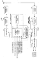
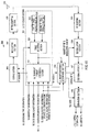
- FIG.7 is a block diagram showing a configuration of BS 100 according to Example 1.
- coding section 101 uses the TF indexes outputted from UL transport format determining section 111 in UL scheduler section 109 (described later) as band allocation information, applies error correcting coding to the band allocation information, and outputs the encoded data sequence to modulation section 102.
- Modulation section 102 converts the coded data sequence outputted from coding section 101 to modulated symbols according to predetermined modulation schemes (QPSK, 16QAM, 64QAM and so on) and outputs the modulated signal to RF transmitting section 103.
- RF transmitting section 103 up-converts the modulated signal outputted from modulation section 102 from a baseband signal to the transmitting band, and transmits the up-converted modulated signal through antenna 104.
- RF receiving section 105 receives the signal transmitted from a MS via antenna 104, down-converts the received signal to a baseband signal and outputs the baseband signal to demodulation section 106.
- Demodulation section 106 estimates and compensates the channel distortion of the baseband signal (received data symbol sequence) outputted from RF receiving section 105, identifies the signal points of the received data symbol sequence subjected to channel distortion compensation, through either of hard decision or soft decision suitable for the modulation of the data, based on the number of RB' s and modulation scheme outputted from UL reception format determining section 112 (described later), and outputs the signal point decision result to decoding section 107.
- Decoding section 107 performs error correction processing on the signal point decision result outputted from demodulation section 106 based on the coding rate outputted from UL reception format determining section 112 and outputs the received data sequence to separation section 108.
- Separation section 108 separates the received data sequence outputted from decoding section 107 into UL user data and L1/L2 control information based on the TB size outputted from UL reception format determining section 112.
- UL scheduler section 109 is provided with transport format (TF) table storage section 110 and UL transport format determining section 111.
- TF table storage section 110 stores a table that combines the basic transport formats (hereinafter “basic TF' s") and derived transport formats (hereinafter "derived TF' s").
- a basic TF defines the number of RB's to allocate and the TB size for when user data alone is transmitted.
- derived TF's are set with TB sizes that vary depending on the combinations of L1/L2 control information that is transmitted at the same time with user data.
- TF table storage section 110 stores a table in which one TF index is assigned in association with a basic TF and a plurality of derived TF's. An appropriate TF index is selected from the stored table, the selected TF index is outputted to UL transport format determining section 111 and the parameters corresponding to the TF index are outputted to UL reception format determining section 112. Details of the TF table will be described later.
- UL transport format determining section 111 determines the number of RB's required for the allocation and transmission parameters, from MS identification information (or "UE-ID"), received signal quality information at the MS matching the MS identifier, band allocation requirement information (the amount of data, transmission rate and so on), DL band allocation information outputted from a DL scheduler section (not shown) and DL CQI allocation information outputted from a CQI scheduler section (not shown), selects the corresponding TF index from TF table storage section 110, and outputs the selected TF index to coding section 101 and UL reception format determining section 112.
- MS identification information or "UE-ID”
- band allocation requirement information the amount of data, transmission rate and so on
- DL band allocation information outputted from a DL scheduler section not shown
- DL CQI allocation information outputted from a CQI scheduler section not shown
- UL reception format determining section 112 acquires the corresponding transmission parameters from TF table storage section 110 based on DL band allocation information outputted from a DL scheduler section (not shown), DL CQI allocation information outputted from a CQI scheduler section (not shown) and the TF index outputted from UL transport format determining section 111, determines the reception format for the UL user data transmitted from a MS on the uplink and determines the reception parameters required for the demodulation, such as the TB size, coding rate, the number of RB's and modulation scheme. The determined number of RB's and modulation scheme are outputted to demodulation section 106, the coding rate is outputted to decoding section 107 and the TB size is outputted to separation section 108.
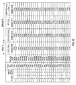
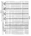
- the TF table is defined in advance as shown in FIG.8 .
- This TF table is stored as a table known to a BS and MS.
- This TF table provides combinations of two types of TF's, namely the basic TF's and derived TF's, and the basic TF's are assigned TF indexes.
- the basic TF's define, for example, the number of RB's to allocate, TB size, modulation scheme and coding rate for when user data alone is transmitted, as shown in FIG.8 .
- derived TF's define TB sizes that vary depending on the combinations of L1/L2 control information to be transmitted at the same time with the user data. That is, derived TF's are provided such that only the number of symbols to be assigned to user data varies, and, as for the other transmission parameters including the M-ary modulation value and coding rate, the same parameters are associated with the same TF index as the basic TF.
- a table is provide in which, in association with basic TF's, derived TF's are provided such that the rate matching by the number of symbols, which decreases and increases depending on whether or not there is L1/L2 control information (and which decreases in FIG.8 ), is controlled by TB size.
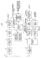
- FIG.9 is a block diagram showing a configuration of MS 150 according to Example 1.
- RF receiving section 152 receives a signal transmitted from BS 100 via antenna 151, down-converts the received signal to a baseband signal and outputs the baseband signal to demodulation section 153.
- Demodulation section 153 estimates and compensates the channel distortion of the baseband signal (received data symbol sequence) outputted from RF receiving section 152, identifies the signal points of the received data symbol sequence subjected to channel distortion compensation through either hard decision or soft decision suitable for the modulation of the data, based on the modulation scheme, and outputs the signal point decision result to decoding section 154.
- Decoding section 154 performs error correction processing on the signal point decision result outputted from demodulation section 153 and outputs the received data sequence to separation section 155.
- Separation section 155 separates the received data sequence outputted from decoding section 154 into user data and UL band allocation information (TF index), and outputs the separated UL band allocation information to UL transport format determining section 157.
- TF index user data and UL band allocation information
- TF table storage section 156 stores the same table as the TF table of BS 100 and UL transport format determining section 157 reads the parameters associated with the TF index, from the stored table.
- UL transport format determining section 157 acquires the TF index outputted from separation section 155 as UL band allocation information, determines a TB size from the TF table based on L1/L2 control information transmission information indicating the presence/absence of L1/L2 control information outputted from a MAC section (not shown), and outputs the determined TB size to TB size setting section 158. Furthermore, UL transport format determining section 157 reads the parameters associated with the TF index from the TF table, and outputs the coding rate out of the read parameters to coding section 159 and the number of RB' s and modulation scheme to modulation section 160.
- TB size setting section 158 sets the TB size of user data to be transmitted according to the TB size outputted from UL transport format determining section 157, adds the CRC bits (here, thirty two bits) to the user data for which the TB size is set, and outputs the user data to coding section 159.
- Coding section 159 adds tail bits and applies error correcting coding to the user data outputted from TB size setting section 158, using the coding rate outputted from UL transport format determining section 157, and outputs the coded data sequence to modulation section 160.
- Modulation section 160 converts the coded data sequence outputted from coding section 159 to modulated symbols, based on the number of RB's and modulation scheme (QPSK, 16QAM, 64QAM and so on) outputted from UL transport format determining section 157, and outputs the modulated signal to multiplexing section 163.
- Coding section 161 applies error correcting coding to L1/L2 control information at a predetermined coding rate, and outputs the coded data sequence to modulation section 162.
- Modulation section 162 converts the coded data sequence outputted from coding section 161 to modulated symbols according to a predetermined modulation scheme and outputs the modulated signal to multiplexing section 163.
- Multiplexing section 163 multiplexes the user data outputted from modulation section 160 and the L1/L2 control information outputted from modulation section 162, and outputs the multiplexed signal to RF transmitting section 164.
- RF transmitting section 164 up-converts the multiplexed signal outputted from multiplexing section 163 from a baseband signal to a transmitting band, and transmits the up-converted multiplexed signal from antenna 151.
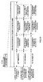
- BS 100 performs DL scheduling for MS 150, transmits DL band allocation information to MS 150, and, in ST202, BS 100 transmits DL user data to MS 150.
- TFI Transmission Time Intervals
- MS 150 which has received UL band allocation information acquires the number of RB's to allocate and the TB size of the basic TF, from the demodulatedTF index. Furthermore, in a subframe in which UL user data is transmitted, MS 150 selects a TB size from the table shown in FIG.8 , according to the presence/absence and combinations of DL ACK/NACK or DL CQI transmission to be transmitted at the same time, performs coding and modulation of the transmission data of the TB size using the transmission parameters associated with the acquired TFI, time multiplexes necessary L1/L2 control information and then carries out uplink transmission.
- BS 100 since the same BS 100 performs the downlink band allocation as well, when performing UL scheduling, if MS 150 receives DL band allocation information correctly, BS 100 knows in advance that DL ACK/NACK are multiplexed upon the same time and only reports the TFI of the basic TF, and, in many cases, MS 150 also performs UL transmission in the TB size intended by BS 100.
- BS 100 demodulates the UL user data, and there can be various cases, including, for example, a case where MS 150 fails to receive DL band allocation information ( FIG.11 ) and a case where a DL CQI is reported under the initiative of the MS. In such a case, MS 150 performs transmission processing on the UL user data using a value different from the TB size intended by BS 100 upon scheduling.
- BS 100 performs blind estimation within the range of TB size corresponding to the TFI reported in the band allocation information or performs demodulation by receiving information indicating the combination of L1/L2 control information from the MS. Even when different L1/L2 control information is multiplexed, the TB size which MS 150 can select is determined in advance in the TF table shown in FIG.8 , so that it is possible to reduce the amount of processing for performing blind estimation.
- Example 1 associates, with same index, basic TF's, which refers to combinations of parameters such as TB size, the number of RB' s to allocate, modulation scheme and coding rate for when user data alone is transmitted, and derived TF's, which have varying TB sizes for user data depending on the combinations of L1/L2 control information, so that, when dynamic symbol allocation is performed in the uplink, transport format can be reported by only reporting the indexes, thereby reducing the number of TF bits of scheduling information and improving frequency utilization efficiency of the uplink without increasing the overhead of control information.
- rate matching is controlled by adjusting the number of information bits to transmit, so that, even when control information is multiplexed upon the same time, the coding rate and modulation scheme need not be changed, and, consequently, the packet error rate is maintained effectively.
- Example 2 The configurations of a BS and MS according to Example 2 are similar to those shown in FIG.7 and FIG.9 of Example 1, respectively, and therefore FIG.7 and FIG. 9 will be used and overlapping explanations will be omitted.
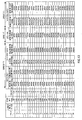
- FIG.12 shows a TF table according to Example 2.
- the basic TF's are combinations of the number of RB's to allocate, TB size, modulation scheme and coding rate for when user data alone is transmitted, and in which derived TF's have coding rates for user data that vary depending on the combinations of L1/L2 control information. That is, parameters such as the number of RB's to allocate, TB size and modulation scheme do not change depending on the combinations of L1/L2 control information.
- Adjustment of the coding rate may also be realized by changing the number of output bits of error correcting code represented by turbo code, convolutional code and LDPC code, and the bit puncturing pattern when puncturing the error correcting coding output. Furthermore, the coding rate may be adjusted also by changing some of the output bits of error correcting coding or the number of all bit repetitions or number of symbol repetitions. Moreover, these methods may be adopted in various combinations.
- the positions of the symbols to be repeated are also shared in advance between the BS and MS in a TF table.
- Example 2 even when user data coding rates varying depending on the combinations of L1/L2 control information are set in the derived TF's, the number of bits for transport format for scheduling information can be reduced, so that uplink frequency utilization efficiency is improved without increasing overhead for control information. Furthermore, rate matching is controlled by changing the coding rate, so that, even when control information is multiplexed upon the same time, the number of information bits to be transmitted does not change and the transmission data rate (i.e. transmission rate) is effectively maintained.
- the derived TF's may be provided with M-ary modulation values, so that, whether or not L1/L2 control information is multiplexed, adequate support is provided by changing the M-ary modulation value with respect to some or all of the symbols transmitted.
- a setup is also possible in which the basic TF's are used when CQI is transmitted.
- the combination of L1/L2 control information to be set in association with a basic TF may be any of all combinations, and may be, preferably, the most frequently occurring combination or a combination that reduces the difference in the reception performance between the basic TF's and derived TF's.
- the positions of symbols whose modulation the M-ary modulation value is changed are also shared in advance between the BS and MS as a TF table.
- Configurations of a BS and MS according to Example 3 are similar to the configurations shown in FIG.7 and FIG.9 of Example 1, and therefore FIG.7 and FIG.9 will be used and overlapping explanations will be omitted.
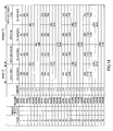
- FIG.14 shows a TF table according to Example 3.
- TB sizes that are associated with combinations of L1/L2 control information on a one to one basis are not provided with respect to all TF indexes. Instead, one TB size is set for several combinations of L1/L2 control information. That is, rate matching of user data is controlled in equal proportions between the combinations of L1/L2 control information.
- TF indexes using modulation schemes of low transmission rates and coding rates show lower frequency utilization efficiency than TF indexes of higher transmission rates, so that radio resource utilization efficiency can be improved by providing more associations with L1/L2 control information.
- Example 3 the number of derived TF's that will have little frequency utilization efficiency improvement effect even if rate adjustment is carried out according to the presence/absence of L1/L2 control information to be multiplexed, the complexity of the transmitter/receiver necessitated by rate matching, can be reduced.
- Parameters for controlling rate matching between combinations of L1/L2 control information are not limited to TB size and so on as described in Example 2, and other parameters such as the coding rate, modulation scheme and the number of RB's to allocate, may be adopted as well.
- the number of derived TF's for a TF index is not limited to the number shown in FIG.14 and may also be set in accordance with the capacity of the BS and MS.
- Example 4 will be explained assuming a case where scheduling is realized by switching between channel dependent scheduling/adaptive scheduling (adaptive time-frequency scheduling according to channel quality, hereinafter simply "adaptive scheduling”) and persistent scheduling/static scheduling.
- adaptive scheduling adaptive time-frequency scheduling according to channel quality
- Adaptive scheduling performs adaptive modulation, adaptive band allocation and adaptive bandwidth allocation according to uplink channel quality and the amount of data required. Furthermore, band allocation information is reported to the MS on the downlink for every band allocation (that is, every scheduling). Examples of adopting adaptive scheduling include application to a MS which moves relatively slowly and to which band of high reception quality and optimal transmission parameters can be assigned every allocation according to instantaneous fluctuation of channel quality, or application to services whose transmission data is generated not regularly but in bursts.
- persistent scheduling allocates the modulation scheme, coding rate, bandwidth and the number of slots, according to uplink channel quality and the amount of data required, and reports band allocation information on the downlink only upon the first band allocation.
- band allocation is performed using predetermined periods and frequency hopping patterns, and therefore uplink user data transmission is performed without reporting band allocation information on the downlink (k shows the number of times fixed allocation determined by the system is performed).
- Examples of application of persistent scheduling include application to constant bit rate services in which transmission data is generated regularly (e.g., VoIP, video streaming, Internet games, etc.) and application to scheduling for a MS which moves fast and which is therefore not suitable for adaptive scheduling.
- FIG.15 is a block diagram showing a configuration of BS 300 according to Example 4.
- FIG. 15 differs from FIG. 7 in that a plurality of TF table storage sections 302 and 303 and table selection section 304 are added and coding section 101 is changed to coding section 305.
- UL scheduler section 301 is provided with first TF table storage section 302, second TF table storage section 303, table selection section 304 and UL transport format determining section 111.
- First TF table storage section 302 stores the TF table shown in FIG.8 and second TF table storage section 303 stores the TF table shown in FIG.12 .
- Table selection section 304 acquires UL scheduling type information showing whether to apply adaptive scheduling or persistent scheduling to a given MS, and selects the table to employ in the band allocation according to the UL scheduling type information.
- the selected TF table is used in UL transport format determining section 111 upon band allocation and used in UL reception format determining section 112 when UL data is received.
- table selection section 304 adopts a table in which TB size is set in derived TF's (i.e. the TF table shown in FIG.8 ), to a MS subject to adaptive scheduling, for maximum frequency utilization efficiency.
- a table in which physical layer parameters such as the coding rate, modulation scheme and the number of repetitions, are set in the derived TF's (i.e. the TF table shown in FIG.12 , for example), is applied.
- a MS is subject to persistent scheduling, its transmission band does not increase or decrease for a certain period, so that it is possible to transmit every time the data to be transmitted by using derived TF's, between which rate matching is controlled based on the coding rate, modulation scheme, the number of repetitions and so on, without changing the TB size, and reduce communication delays and jitter.
- band allocation information is transmitted only upon the first transmission and band allocation information is generally not transmitted upon the second to K-th band allocations for UL user data.
- Coding section 305 applies error correcting coding to UL scheduling type information in addition to the TF index as band allocation information outputted from UL transport format determining section 111, and outputs the coded data sequence to modulation section 102.
- FIG.16 is a block diagram showing a configuration of MS 350 according to Example 4 of the present invention.
- FIG.16 differs from FIG.9 in that a plurality of TF table storage sections 351 and 352 and table selection section 353 are added.
- first TF table storage section 351 stores the TF table shown in FIG.8 and second TF table storage section 352 stores the TF table shown in FIG.12 .
- Table selection section 353 acquires UL scheduling type information outputted from separation section 155, and selects the table to employ in the band allocation according to the UL scheduling type information.
- the selected TF table is used in UL transport format determining section 157 upon band allocation.
- Example 4 if a MS is subject to persistent scheduling, the transmission band does not increase or decrease for a certain period, so that the data to be transmitted is reliably transmitted every time and communication delay and jitter are reduced by controlling the rate matching without changing the TB size.
- a MS that is subj ect to adaptive scheduling is controlled using the latest CQI upon every band allocation, so that frequency utilization efficiency can be improved by controlling rate matching according to TB size.
- the present Example has been explained with reference to a case where two TF tables are switched, but the present technique is not limited to this, and more TF tables may be switched.
- Example 5 will explain a case assuming a system adopting HARQ (Hybrid Automatic Repeat reQuest) based on the IR (Incremental redundancy) scheme.
- HARQ Hybrid Automatic Repeat reQuest
- FIG.17 is a block diagram showing a configuration of BS 400 according to Example 5.
- FIG.17 differs from FIG.7 in that a plurality of TF table storage sections 402 and 403 and table selection section 404 are added.
- UL scheduler section 401 is provided with first TF table storage section 402, second TF table storage section 403, table selection section 404 and UL transport format determining section 111.
- TF table storage section 402 stores the first table shown in FIG.8 , FIG.12 , FIG.13 , FIG.14 and so on, and second TF table storage section 403 stores a second table in which derived TF's are provided with different number of retransmission bits depending on the combinations of L1/L2 control information.
- the selected TF table is used in UL transport format determining section 111 upon band allocation and used in UL reception format determining section 112 when UL data is received.
- FIG.18 is a block diagram showing a configuration of MS 450 according to Example 5.
- FIG.18 differs from FIG.9 in that a plurality of TF table storage sections 451 and 452 and table selection section 453 are added.
- first TF table storage section 451 stores the first table shown in FIG.8 , FIG.12 , FIG.13 , FIG.14 and so on
- second TF table storage section 452 stores a second table in which the number of bits transmitted upon retransmission is set in derived TF's according to the combinations of L1/L2 control information.
- Table selection section 453 acquires retransmission count information and selects a table to be applied to band allocation according to the count of UL user data retransmissions.
- the count of retransmissions is determined by counting the number of times NACK is reported from the BS for the same UL user data transmission packet.
- FIG.19 shows a TF table according to Example 5.
- the derived TF's are provided such that the number of retransmission bits varies depending on the combinations of L1/L2 control information.
- the number of retransmission bits varies between retransmissions, for example, more specifically, the following adjustment may be carried out.
- the present Example assumes an IR-based HARQ system, and, in this system, redundant transmission bits are added every time a retransmission occurs, as shown in FIG.20 , and therefore the number of redundant bits to be retransmitted is adjusted according to the presence/absence or combinations of L1/L2 control information. Therefore, the number of redundant bits to be transmitted is lower when there is L1/L2 control information, than in a case where there is no L1/L2 control information ( FIG.20(a) ). As for the location the redundant bits to be transmitted upon a retransmission starts being transmitted, the retransmission may be started from the next redundant bit from the previous transmission, as shown in FIG.20(b) .
- retransmission may be performed from the bit position where transmission takes place when L1/L2 control information is not multiplexed.
- the position the redundant bits start being transmitted, may be shared in advance between the BS and MS.
- Example 5 the rate matching between retransmissions is controlled by adjusting the number of redundant bits to be retransmitted and the redundant bit selection pattern, so that, even when L1/L2 control information is multiplexed upon retransmission, redundant bits can be transmitted effectively.
- Example 5 is especially effective in synchronous HARQ where UL band allocation information is not reported on the downlink upon retransmissions.
- the present Example has explained the details of adjustment for when the number of retransmission bits varies upon retransmission assuming a HARQ system based on the IR scheme, and adjustment for HARQ applied to the HSDPA (High Speed Downlink Packet Access) system described in Non-Patent Document 3, is as follows. That is, the rate matching and transmission bits upon retransmission are determined by the parameter "s" and parameter "r" of the RV (Redundancy Version) variable, which is reported in band allocation information.
- the parameter "s" is a mode in which systematic bits are preferentially retransmitted, so that systematic bits are selected as the bits to be retransmitted with reference to the number of retransmission bits shown in the TF table, and parity bits are further transmitted when there are a sufficient number of retransmission bits.
- parameter s is a mode in which parity bits are preferentially retransmitted, so that parity bits are selected as bits to be retransmitted with respect to the number of retransmission bits shown in the TF table and systematic bits are further transmitted if there are a sufficient number of retransmission bits.
- Parameter r is a parameter indicating the retransmission count and determines the position at which bit puncturing is started.
- the present technique is not limited to this and may also be adapted to switch more tables.
- the TF table upon retransmission may be switched for every retransmission count.
- Example 4 may also be combined with Example 4.
- the present technique is not limited to this , and, when, for example, the number of symbols of DATA, M-ary modulation value and coding rate vary according to channel quality and so on, the number of symbols of L1/L2 control information, M-ary modulation value and coding rate may be determined according to these changes.
- Each function block employed in the description of each of the aforementioned Examples may typically be implemented as an LSI constituted by an integrated circuit. These may be individual chips or partially or totally contained on a single chip. "LSI” is adopted here but this may also be referred to as “IC,” “system LSI, “ “super LSI,” or “ultra LSI” depending on differing extents of integration.
- circuit integration is not limited to LSI's, and implementation using dedicated circuitry or general purpose processors is also possible.
- LSI manufacture utilization of a programmable FPGA (Field Programmable Gate Array) or a reconfigurable processor where connections and settings of circuit cells within an LSI can be reconfigured is also possible.
- FPGA Field Programmable Gate Array
- the radio transmitting apparatus and radio transmission method according to the present invention can improve throughputs of a downlink and uplink even when performing dynamic symbol allocation and is applicable, for example, to a 3GPP LTE radio communication system.
Landscapes
- Engineering & Computer Science (AREA)
- Computer Networks & Wireless Communication (AREA)
- Signal Processing (AREA)
- Quality & Reliability (AREA)
- Mobile Radio Communication Systems (AREA)
- Detection And Prevention Of Errors In Transmission (AREA)
- Digital Transmission Methods That Use Modulated Carrier Waves (AREA)
- Communication Control (AREA)
Claims (9)
- Appareil d'émission radio (150, 350, 450) comprenant :- une unité de réception (152) configurée pour recevoir un indice indiquant un format d'émission incluant une taille de bloc de transport, taille de TB, pour des données utilisateur ;- une unité de codage (159, 161) configurée pour coder les données utilisateur et des informations de commande utilisant le format d'émission ; et- une unité d'émission (164) configurée pour émettre les données utilisateur codées et les informations de commande,- caractérisé en ce que ladite unité de codage ajuste un débit de code des données utilisateur pour la taille de TB du format d'émission suivant une combinaison avec les informations de commande à émettre avec les données utilisateur.
- Appareil d'émission radio selon la revendication 1, dans lequel un paramètre d'émission pour les données utilisateur est fixé dans le format d'émission.
- Appareil d'émission radio selon les revendications 1 ou 2, dans lequel un schéma de modulation est inclus dans le format d'émission.
- Appareil d'émission radio selon l'une quelconque des revendications 1 à 3, dans lequel les informations de commande sont un ACK/NACK ou un CQI.
- Appareil d'émission radio selon l'une quelconque des revendications 1 à 4, comprenant, en outre, une unité de stockage (156) configurée pour stocker une relation entre l'indice et le format d'émission, dans lequel ladite unité de codage utilise le format d'émission obtenu en se référant à l'indice et à la relation.
- Appareil d'émission radio selon l'une quelconque des revendications 1 à 5, dans lequel :- la taille de TB pour les données utilisateur n'est pas fait varier suivant la combinaison avec les informations de commande.
- Appareil d'émission radio selon l'une quelconque des revendications 1 à 6, dans lequel ladite unité de codage fait varier le débit de code des données utilisateur suivant la combinaison avec les informations de commande.
- Appareil d'émission radio selon l'une quelconque des revendications 1 à 7, dans lequel ladite unité de codage fait coïncider le débit pour les données utilisateur en ajustant le débit de code.
- Procédé d'émission radio, consistant à :- recevoir un indice indiquant un format d'émission incluant une taille de bloc de transport, taille de TB, pour des données utilisateur ;- coder les informations de commande et les données utilisateur utilisant le format d'émission ; et- caractérisé en ce qu'un débit de code des données utilisateur pour la taille de TB du format d'émission est ajusté suivant une combinaison avec les informations de commande à émettre avec les données utilisateur.
Priority Applications (4)
| Application Number | Priority Date | Filing Date | Title |
|---|---|---|---|
| EP24164180.2A EP4362592A2 (fr) | 2006-05-19 | 2007-05-18 | Dispositif et procédé de transmission radio |
| PL14200199T PL2866364T3 (pl) | 2006-05-19 | 2007-05-18 | Urządzenie do transmisji radiowej i sposób transmisji radiowej |
| EP14200199.9A EP2866364B1 (fr) | 2006-05-19 | 2007-05-18 | Dispositif de transmission radio et procédé de transmission radio |
| EP19196910.4A EP3606245A1 (fr) | 2006-05-19 | 2007-05-18 | Dispositif de transmission radio et procédé de transmission radio |
Applications Claiming Priority (2)
| Application Number | Priority Date | Filing Date | Title |
|---|---|---|---|
| JP2006140462 | 2006-05-19 | ||
| PCT/JP2007/060258 WO2007136002A1 (fr) | 2006-05-19 | 2007-05-18 | dispositif de transmission radio et procÉdÉ de transmission radio |
Related Child Applications (4)
| Application Number | Title | Priority Date | Filing Date |
|---|---|---|---|
| EP14200199.9A Division EP2866364B1 (fr) | 2006-05-19 | 2007-05-18 | Dispositif de transmission radio et procédé de transmission radio |
| EP14200199.9A Division-Into EP2866364B1 (fr) | 2006-05-19 | 2007-05-18 | Dispositif de transmission radio et procédé de transmission radio |
| EP24164180.2A Division EP4362592A2 (fr) | 2006-05-19 | 2007-05-18 | Dispositif et procédé de transmission radio |
| EP19196910.4A Division EP3606245A1 (fr) | 2006-05-19 | 2007-05-18 | Dispositif de transmission radio et procédé de transmission radio |
Publications (3)
| Publication Number | Publication Date |
|---|---|
| EP2019559A1 EP2019559A1 (fr) | 2009-01-28 |
| EP2019559A4 EP2019559A4 (fr) | 2014-03-19 |
| EP2019559B1 true EP2019559B1 (fr) | 2015-04-08 |
Family
ID=38723313
Family Applications (4)
| Application Number | Title | Priority Date | Filing Date |
|---|---|---|---|
| EP19196910.4A Pending EP3606245A1 (fr) | 2006-05-19 | 2007-05-18 | Dispositif de transmission radio et procédé de transmission radio |
| EP14200199.9A Active EP2866364B1 (fr) | 2006-05-19 | 2007-05-18 | Dispositif de transmission radio et procédé de transmission radio |
| EP24164180.2A Pending EP4362592A2 (fr) | 2006-05-19 | 2007-05-18 | Dispositif et procédé de transmission radio |
| EP07743693.9A Active EP2019559B1 (fr) | 2006-05-19 | 2007-05-18 | Dispositif de transmission radio et procede de transmission radio |
Family Applications Before (3)
| Application Number | Title | Priority Date | Filing Date |
|---|---|---|---|
| EP19196910.4A Pending EP3606245A1 (fr) | 2006-05-19 | 2007-05-18 | Dispositif de transmission radio et procédé de transmission radio |
| EP14200199.9A Active EP2866364B1 (fr) | 2006-05-19 | 2007-05-18 | Dispositif de transmission radio et procédé de transmission radio |
| EP24164180.2A Pending EP4362592A2 (fr) | 2006-05-19 | 2007-05-18 | Dispositif et procédé de transmission radio |
Country Status (12)
| Country | Link |
|---|---|
| US (6) | US8488692B2 (fr) |
| EP (4) | EP3606245A1 (fr) |
| JP (3) | JP4654294B2 (fr) |
| KR (2) | KR101365373B1 (fr) |
| CN (2) | CN101449501B (fr) |
| BR (1) | BRPI0712598B1 (fr) |
| ES (1) | ES2773861T3 (fr) |
| IN (1) | IN2014MN02527A (fr) |
| MX (1) | MX2008014738A (fr) |
| PL (1) | PL2866364T3 (fr) |
| RU (2) | RU2454807C2 (fr) |
| WO (1) | WO2007136002A1 (fr) |
Cited By (1)
| Publication number | Priority date | Publication date | Assignee | Title |
|---|---|---|---|---|
| US10959120B2 (en) | 2005-12-22 | 2021-03-23 | Qualcomm Incorporated | Methods and apparatus related to selecting control channel reporting formats |
Families Citing this family (49)
| Publication number | Priority date | Publication date | Assignee | Title |
|---|---|---|---|---|
| WO2007136002A1 (fr) * | 2006-05-19 | 2007-11-29 | Panasonic Corporation | dispositif de transmission radio et procÉdÉ de transmission radio |
| RU2009134938A (ru) * | 2007-03-01 | 2011-04-10 | НТТ ДоСоМо, Инк. (JP) | Базовая станция и способ управления связью |
| KR101494002B1 (ko) * | 2007-06-11 | 2015-02-16 | 삼성전자주식회사 | 이동통신 시스템에서 자원 할당 및 그에 따른 수신 장치 및방법 |
| US8412209B2 (en) | 2007-06-18 | 2013-04-02 | Motorola Mobility Llc | Use of the physical uplink control channel in a 3rd generation partnership project communication system |
| AU2008265134C1 (en) | 2007-06-19 | 2014-09-25 | Beijing Xiaomi Mobile Software Co.,Ltd. | Adaptive transport format uplink signaling for data-non-associated feedback control signals |
| ES2550683T3 (es) | 2007-06-19 | 2015-11-11 | Panasonic Intellectual Property Corporation Of America | Circuito de disposición de canal para comunicación de radio |
| CN101689951A (zh) * | 2007-06-28 | 2010-03-31 | 松下电器产业株式会社 | 发送装置、发送方法、接收装置及接收方法 |
| US20090067603A1 (en) * | 2007-09-07 | 2009-03-12 | Avaya Technology Llc | Pre-arranged, mutually agreed to, VoIP or VoIM call |
| KR100932555B1 (ko) * | 2007-12-03 | 2009-12-17 | 한국전자통신연구원 | 이동통신 시스템의 자원할당 방법 |
| JP5061892B2 (ja) | 2007-12-28 | 2012-10-31 | 富士通株式会社 | 無線通信システムにおける信号多重方法、送信局及び受信局 |
| BRPI0822232B1 (pt) * | 2008-01-04 | 2020-02-04 | Godo Kaisha Ip Bridge 1 | aparelho de radiotransmissão e método de radiotransmissão |
| EP2242303B1 (fr) * | 2008-02-03 | 2013-01-09 | LG Electronics Inc. | Procédé de transmission d'indicateurs de qualité des voies (cqi) dans un système de communication sans fil |
| MX2010008596A (es) * | 2008-02-04 | 2010-08-31 | Samsung Electronics Co Ltd | Multiplexion de control y datos en sistemas de comunicacion. |
| JP5041597B2 (ja) * | 2008-02-27 | 2012-10-03 | Kddi株式会社 | 無線リソースの割り当てをスケジューリングする基地局、方法及びプログラム |
| JP5115802B2 (ja) * | 2008-03-11 | 2013-01-09 | 富士通株式会社 | スケジューリング装置、スケジューリング方法、およびプログラム |
| JP5386573B2 (ja) | 2008-03-21 | 2014-01-15 | インターデイジタル パテント ホールディングス インコーポレイテッド | フィードバック信号方式の方法および装置 |
| US8179783B2 (en) * | 2008-08-13 | 2012-05-15 | Telefonaktiebolaget L M Ericsson (Publ) | System and method of modulation and coding scheme adjustment for a LTE shared data channel |
| US8730933B2 (en) * | 2008-09-18 | 2014-05-20 | Qualcomm Incorporated | Method and apparatus for multiplexing data and reference signal in a wireless communication system |
| US8422439B2 (en) * | 2008-12-31 | 2013-04-16 | Motorola Mobility Llc | Apparatus and method for communicating control information over a data channel in the absence of user data |
| US20100184450A1 (en) * | 2009-01-16 | 2010-07-22 | Xuemin Sherman Chen | Method and system for controlling parameters of a communication channel between a femtocell and a cellular enabled communication device |
| JP4898858B2 (ja) | 2009-03-02 | 2012-03-21 | パナソニック株式会社 | 符号化器、復号化器及び符号化方法 |
| US8737335B2 (en) * | 2009-06-19 | 2014-05-27 | Kddi Corporation | Reference signal transmission scheduling device and reference signal transmission scheduling method |
| US9288026B2 (en) * | 2009-06-22 | 2016-03-15 | Qualcomm Incorporated | Transmission of reference signal on non-contiguous clusters of resources |
| US9014138B2 (en) * | 2009-08-07 | 2015-04-21 | Blackberry Limited | System and method for a virtual carrier for multi-carrier and coordinated multi-point network operation |
| CN102013938B (zh) * | 2009-12-07 | 2012-07-04 | 华为技术有限公司 | 传输上行控制信息的方法和装置 |
| JP5573167B2 (ja) * | 2010-01-06 | 2014-08-20 | 日本電気株式会社 | コンテンツ共有システム,コンテンツ共有方法及びプログラム |
| JP5337843B2 (ja) * | 2011-06-29 | 2013-11-06 | アンリツ株式会社 | 移動通信端末試験装置及び移動通信端末試験方法 |
| US8842641B2 (en) * | 2011-08-12 | 2014-09-23 | Telefonaktiebolaget L M Ericsson (Publ) | RAKE resource multiplexing for enhanced uplink data services |
| US20150326305A1 (en) * | 2012-05-01 | 2015-11-12 | Metanoia Communications Inc. | Framing Mechanism For Time-Division-Duplex OFDM Communication Systems |
| JP5445624B2 (ja) * | 2012-06-08 | 2014-03-19 | 富士通株式会社 | 送信局及び受信局 |
| US9144080B2 (en) * | 2012-11-07 | 2015-09-22 | Telefonaktiebolaget L M Ericsson (Publ) | Selecting transmission parameters for downlink transmissions based on retransmission rates |
| CN105122700B (zh) * | 2012-12-10 | 2018-05-11 | Lg电子株式会社 | 在支持超高频的无线接入系统中发送系统信息的方法及支持该方法的装置 |
| GB2513122A (en) * | 2013-04-15 | 2014-10-22 | Vodafone Intellectual Property Licensing Ltd | Uplink control channel overhead reduction |
| JP2016025560A (ja) * | 2014-07-23 | 2016-02-08 | 株式会社デンソー | データ生成装置およびデータ処理装置 |
| WO2016121341A1 (fr) * | 2015-01-28 | 2016-08-04 | 日本電気株式会社 | Émetteur optique, système de communication optique, et procédé de communication optique |
| KR101755224B1 (ko) * | 2015-06-09 | 2017-07-11 | 한국철도기술연구원 | 인덱스 코딩과 통계적 특성을 이용한 데이터 재전송 시스템 및 방법 |
| WO2017087452A1 (fr) | 2015-11-16 | 2017-05-26 | Hill-Rom Services, Inc. | Systèmes de détection d'incontinence pour lits d'hôpital |
| CN107306453B (zh) * | 2016-04-25 | 2019-12-17 | 华为技术有限公司 | 一种生成传输块的方法和装置 |
| US10469196B2 (en) * | 2016-08-10 | 2019-11-05 | Telefonaktiebolaget Lm Ericsson (Publ) | Check positions within a transport block |
| US10492084B2 (en) | 2016-10-10 | 2019-11-26 | Microsoft Technology Licensing, Llc | Collaborative communications |
| WO2018230992A1 (fr) | 2017-06-15 | 2018-12-20 | 삼성전자 주식회사 | Un procédé et appareil pour effectuer un codage et un décodage de canal dans un système de communication ou de diffusion |
| KR102414531B1 (ko) * | 2017-06-15 | 2022-06-30 | 삼성전자 주식회사 | 통신 또는 방송 시스템에서 채널 부호화/복호화 방법 및 장치 |
| US10686575B2 (en) | 2017-06-23 | 2020-06-16 | Samsung Electronics Co., Ltd. | Method and apparatus for wireless communication using modulation, coding schemes, and transport block sizes |
| JP7058087B2 (ja) * | 2017-07-03 | 2022-04-21 | シャープ株式会社 | 端末装置、基地局装置、および、通信方法 |
| MA47865B1 (fr) * | 2017-08-24 | 2020-09-30 | Ericsson Telefon Ab L M | Sélection de graphe de base pour une nouvelle radio 3gpp |
| JP7074848B2 (ja) * | 2017-10-03 | 2022-05-24 | テレフオンアクチーボラゲット エルエム エリクソン(パブル) | 複数のベースグラフを用いたtbs判定 |
| CN110034848B (zh) | 2018-01-12 | 2021-03-23 | 华为技术有限公司 | 一种信息传输方法和装置 |
| CN110211416B (zh) * | 2019-06-06 | 2021-12-21 | 广域铭岛数字科技有限公司 | 物联网智能车库的信息传输方法及系统 |
| US11509420B2 (en) * | 2020-10-06 | 2022-11-22 | Qualcomm Incorporated | Methods and apparatus for FEC rate adaptation |
Family Cites Families (37)
| Publication number | Priority date | Publication date | Assignee | Title |
|---|---|---|---|---|
| FI107220B (fi) * | 1998-11-06 | 2001-06-15 | Nokia Networks Oy | Menetelmä kantajien ominaisuuksien hallitsemiseksi |
| JP4160072B2 (ja) | 1998-11-25 | 2008-10-01 | 株式会社半導体エネルギー研究所 | 半導体装置の作製方法 |
| US6850759B2 (en) | 2001-02-22 | 2005-02-01 | Telefonaktiebolaget Lm Ericsson (Publ) | Reducing signaling in RNSAP protocol upon cell change in cellular telecommunications network |
| GB2377586B (en) * | 2001-07-06 | 2005-06-29 | Ipwireless Inc | System and method for channel transport format allocation in a wireless communication system |
| KR100450938B1 (ko) * | 2001-10-05 | 2004-10-02 | 삼성전자주식회사 | 고속 순방향 패킷 접속 방식을 사용하는 통신 시스템에서트랜스포트 블록 셋 크기 정보를 송수신하는 장치 및 방법 |
| US6747958B2 (en) * | 2001-11-13 | 2004-06-08 | Qualcomm, Incorporated | Transport format combination selection for compressed mode in a W-CDMA system |
| KR100754552B1 (ko) * | 2001-12-28 | 2007-09-05 | 삼성전자주식회사 | 고속 순방향 패킷 접속 방식을 사용하는 통신 시스템에서고속 공통 제어 채널 송수신 장치 및 방법 |
| US9270410B2 (en) * | 2002-04-22 | 2016-02-23 | Texas Instruments Incorporated | MIMO PGRC system and method |
| US7149245B2 (en) | 2002-04-29 | 2006-12-12 | Lucent Technologies Inc. | Link adaption in enhanced general packet radio service networks |
| KR100876765B1 (ko) * | 2002-05-10 | 2009-01-07 | 삼성전자주식회사 | 이동 통신 시스템에서 데이터 재전송 장치 및 방법 |
| WO2004025883A1 (fr) | 2002-09-12 | 2004-03-25 | Matsushita Electric Industrial Co., Ltd. | Dispositif de transmission radio, dispositif de reception radio, et procede pour une selection de sous-porteuses d'annulation de transmission |
| US7289452B2 (en) | 2002-10-24 | 2007-10-30 | Nokia Corporation | Transport block size (TBS) signaling enhancement |
| JP3796212B2 (ja) * | 2002-11-20 | 2006-07-12 | 松下電器産業株式会社 | 基地局装置及び送信割り当て制御方法 |
| US7408902B2 (en) * | 2003-02-13 | 2008-08-05 | Interdigital Technology Corporation | Method of using a radio network controller for controlling data bit rates to maintain the quality of radio links |
| JP2006517752A (ja) * | 2003-02-14 | 2006-07-27 | シーメンス アクチエンゲゼルシヤフト | データ伝送方法 |
| KR100678182B1 (ko) * | 2003-08-20 | 2007-02-02 | 삼성전자주식회사 | 비동기 광대역 부호분할 다중접속 시스템에서 상향링크 패킷 데이터 서비스 방법 및 장치 |
| KR100995031B1 (ko) | 2003-10-01 | 2010-11-19 | 엘지전자 주식회사 | 다중입력 다중출력 시스템에 적용되는 신호 전송 제어 방법 |
| KR100981580B1 (ko) | 2003-12-23 | 2010-09-10 | 삼성전자주식회사 | 8 개 이하의 송신 안테나를 사용하는 차등 시공간 블록 부호 송수신 장치 |
| US7333556B2 (en) * | 2004-01-12 | 2008-02-19 | Intel Corporation | System and method for selecting data rates to provide uniform bit loading of subcarriers of a multicarrier communication channel |
| US20050237932A1 (en) | 2004-04-23 | 2005-10-27 | Jung-Tao Liu | Method and system for rate-controlled mode wireless communications |
| JP4421935B2 (ja) * | 2004-04-30 | 2010-02-24 | 株式会社エヌ・ティ・ティ・ドコモ | 無線基地局装置及び無線通信制御方法 |
| KR100754722B1 (ko) * | 2004-05-12 | 2007-09-03 | 삼성전자주식회사 | 무선 통신 시스템에서 채널 상태 정보를 이용한 데이터송수신 장치 및 방법 |
| KR100804114B1 (ko) * | 2004-06-17 | 2008-02-18 | 가부시키가이샤 엔.티.티.도코모 | 전송 속도 제어 방법, 송신 전력 제어 방법, 송신 전력비제어 방법, 이동 통신 시스템, 이동국 및 무선 기지국 |
| EP1617606A1 (fr) * | 2004-07-16 | 2006-01-18 | Matsushita Electric Industrial Co., Ltd. | Planification de transfert de mode pour des transmissions en montantes |
| JP4355631B2 (ja) * | 2004-08-11 | 2009-11-04 | 株式会社エヌ・ティ・ティ・ドコモ | 移動通信システム及び移動局 |
| CN1756254B (zh) * | 2004-09-29 | 2011-01-12 | 上海贝尔阿尔卡特股份有限公司 | 无线链路控制层的分段方法 |
| GB0421663D0 (en) * | 2004-09-29 | 2004-10-27 | Nokia Corp | Transmitting data in a wireless network |
| DE602004012862T2 (de) * | 2004-10-01 | 2009-04-09 | Matsushita Electric Industrial Co., Ltd., Kadoma-shi | Dienstgüte-bewusste Ablaufsteuerung für Aufwärtsübertragungen über zugeordneten Kanälen |
| US8826328B2 (en) * | 2004-11-12 | 2014-09-02 | Opentv, Inc. | Communicating primary content streams and secondary content streams including targeted advertising to a remote unit |
| US20060281417A1 (en) | 2005-05-10 | 2006-12-14 | Ntt Docomo, Inc. | Transmission rate control method and mobile station |
| US7403470B2 (en) * | 2005-06-13 | 2008-07-22 | Qualcomm Incorporated | Communications system, methods and apparatus |
| US8731562B2 (en) * | 2005-08-30 | 2014-05-20 | Telefonaktiebolaget L M Ericsson (Publ) | Detection of control messages for HSDPA |
| CN100486252C (zh) * | 2005-10-18 | 2009-05-06 | 中兴通讯股份有限公司 | 支持多载波高速下行分组接入的数据并行调度系统及方法 |
| US20070171849A1 (en) | 2006-01-03 | 2007-07-26 | Interdigital Technology Corporation | Scheduling channel quality indicator and acknowledgement/negative acknowledgement feedback |
| US7903614B2 (en) * | 2006-04-27 | 2011-03-08 | Interdigital Technology Corporation | Method and apparatus for selecting link adaptation parameters for CDMA-based wireless communication systems |
| WO2007136002A1 (fr) * | 2006-05-19 | 2007-11-29 | Panasonic Corporation | dispositif de transmission radio et procÉdÉ de transmission radio |
| US20120018883A1 (en) | 2007-09-13 | 2012-01-26 | Geng-Shin Shen | Conductive structure for a semiconductor integrated circuit |
-
2007
- 2007-05-18 WO PCT/JP2007/060258 patent/WO2007136002A1/fr active Search and Examination
- 2007-05-18 EP EP19196910.4A patent/EP3606245A1/fr active Pending
- 2007-05-18 PL PL14200199T patent/PL2866364T3/pl unknown
- 2007-05-18 EP EP14200199.9A patent/EP2866364B1/fr active Active
- 2007-05-18 RU RU2008150306/07A patent/RU2454807C2/ru active
- 2007-05-18 EP EP24164180.2A patent/EP4362592A2/fr active Pending
- 2007-05-18 MX MX2008014738A patent/MX2008014738A/es active IP Right Grant
- 2007-05-18 ES ES14200199T patent/ES2773861T3/es active Active
- 2007-05-18 US US12/301,441 patent/US8488692B2/en active Active
- 2007-05-18 CN CN2007800180712A patent/CN101449501B/zh active Active
- 2007-05-18 KR KR1020087028281A patent/KR101365373B1/ko active IP Right Grant
- 2007-05-18 BR BRPI0712598-4A patent/BRPI0712598B1/pt active IP Right Grant
- 2007-05-18 JP JP2008516673A patent/JP4654294B2/ja active Active
- 2007-05-18 KR KR1020117029441A patent/KR101365374B1/ko active IP Right Grant
- 2007-05-18 CN CN201110162006.5A patent/CN102223205B/zh active Active
- 2007-05-18 IN IN2527MUN2014 patent/IN2014MN02527A/en unknown
- 2007-05-18 EP EP07743693.9A patent/EP2019559B1/fr active Active
-
2010
- 2010-12-17 JP JP2010281700A patent/JP5001420B2/ja active Active
-
2012
- 2012-03-21 RU RU2012110822/07A patent/RU2494549C1/ru active
- 2012-05-16 JP JP2012112219A patent/JP5504303B2/ja active Active
-
2013
- 2013-06-14 US US13/918,654 patent/US9432972B2/en active Active
-
2016
- 2016-07-21 US US15/216,641 patent/US10827466B2/en active Active
-
2020
- 2020-09-29 US US17/037,518 patent/US11470583B2/en active Active
-
2022
- 2022-08-30 US US17/899,352 patent/US11765726B2/en active Active
-
2023
- 2023-08-08 US US18/446,193 patent/US20230389025A1/en active Pending
Cited By (1)
| Publication number | Priority date | Publication date | Assignee | Title |
|---|---|---|---|---|
| US10959120B2 (en) | 2005-12-22 | 2021-03-23 | Qualcomm Incorporated | Methods and apparatus related to selecting control channel reporting formats |
Also Published As
Similar Documents
| Publication | Publication Date | Title |
|---|---|---|
| US11765726B2 (en) | Radio transmission device and radio transmission method | |
| US10547432B2 (en) | Method and apparatus for selecting multiple transport formats and transmitting multiple transport blocks simultaneously with multiple H-ARQ processes | |
| JP5061095B2 (ja) | 無線通信システム、無線送信装置、および再送方法 | |
| EP2420017B1 (fr) | Sélection de la taille d'une unité de données d'un protocole de commande de liaison radio dans un hsupa à double porteuse | |
| EP1835631A1 (fr) | Procede de transmission par un canal de signalisation, station de base et terminal | |
| KR20130130097A (ko) | 다중 h-arq 프로세스를 사용하여 동시에 다중 전송 포맷을 선택하고 다중 전송 블럭을 송신하는 방법 및 장치 |
Legal Events
| Date | Code | Title | Description |
|---|---|---|---|
| PUAI | Public reference made under article 153(3) epc to a published international application that has entered the european phase |
Free format text: ORIGINAL CODE: 0009012 |
|
| 17P | Request for examination filed |
Effective date: 20081114 |
|
| AK | Designated contracting states |
Kind code of ref document: A1 Designated state(s): AT BE BG CH CY CZ DE DK EE ES FI FR GB GR HU IE IS IT LI LT LU LV MC MT NL PL PT RO SE SI SK TR |
|
| AX | Request for extension of the european patent |
Extension state: AL BA HR MK RS |
|
| DAX | Request for extension of the european patent (deleted) | ||
| A4 | Supplementary search report drawn up and despatched |
Effective date: 20140219 |
|
| RIC1 | Information provided on ipc code assigned before grant |
Ipc: H04L 1/00 20060101ALI20140213BHEP Ipc: H04L 27/38 20060101ALI20140213BHEP Ipc: H04W 72/04 20090101ALI20140213BHEP Ipc: H04L 27/22 20060101ALI20140213BHEP Ipc: H04L 1/16 20060101ALI20140213BHEP Ipc: H04L 27/20 20060101ALI20140213BHEP Ipc: H04L 27/36 20060101ALI20140213BHEP Ipc: H04J 1/00 20060101AFI20140213BHEP |
|
| RAP1 | Party data changed (applicant data changed or rights of an application transferred) |
Owner name: PANASONIC INTELLECTUAL PROPERTY CORPORATION OF AME |
|
| REG | Reference to a national code |
Ref country code: DE Ref legal event code: R079 Ref document number: 602007040967 Country of ref document: DE Free format text: PREVIOUS MAIN CLASS: H04Q0007360000 Ipc: H04J0001000000 |
|
| GRAP | Despatch of communication of intention to grant a patent |
Free format text: ORIGINAL CODE: EPIDOSNIGR1 |
|
| RIC1 | Information provided on ipc code assigned before grant |
Ipc: H04L 1/16 20060101ALI20141014BHEP Ipc: H04L 27/22 20060101ALI20141014BHEP Ipc: H04L 27/20 20060101ALI20141014BHEP Ipc: H04L 27/38 20060101ALI20141014BHEP Ipc: H04J 1/00 20060101AFI20141014BHEP Ipc: H04L 27/36 20060101ALI20141014BHEP Ipc: H04W 72/04 20090101ALI20141014BHEP Ipc: H04L 1/00 20060101ALI20141014BHEP |
|
| INTG | Intention to grant announced |
Effective date: 20141030 |
|
| GRAS | Grant fee paid |
Free format text: ORIGINAL CODE: EPIDOSNIGR3 |
|
| GRAA | (expected) grant |
Free format text: ORIGINAL CODE: 0009210 |
|
| AK | Designated contracting states |
Kind code of ref document: B1 Designated state(s): AT BE BG CH CY CZ DE DK EE ES FI FR GB GR HU IE IS IT LI LT LU LV MC MT NL PL PT RO SE SI SK TR |
|
| REG | Reference to a national code |
Ref country code: GB Ref legal event code: FG4D |
|
| REG | Reference to a national code |
Ref country code: CH Ref legal event code: EP |
|
| REG | Reference to a national code |
Ref country code: IE Ref legal event code: FG4D |
|
| REG | Reference to a national code |
Ref country code: AT Ref legal event code: REF Ref document number: 721254 Country of ref document: AT Kind code of ref document: T Effective date: 20150515 |
|
| REG | Reference to a national code |
Ref country code: DE Ref legal event code: R096 Ref document number: 602007040967 Country of ref document: DE Effective date: 20150521 Ref country code: FR Ref legal event code: PLFP Year of fee payment: 9 |
|
| REG | Reference to a national code |
Ref country code: AT Ref legal event code: MK05 Ref document number: 721254 Country of ref document: AT Kind code of ref document: T Effective date: 20150408 |
|
| REG | Reference to a national code |
Ref country code: NL Ref legal event code: VDEP Effective date: 20150408 |
|
| REG | Reference to a national code |
Ref country code: LT Ref legal event code: MG4D |
|
| PG25 | Lapsed in a contracting state [announced via postgrant information from national office to epo] |
Ref country code: NL Free format text: LAPSE BECAUSE OF FAILURE TO SUBMIT A TRANSLATION OF THE DESCRIPTION OR TO PAY THE FEE WITHIN THE PRESCRIBED TIME-LIMIT Effective date: 20150408 |
|
| PG25 | Lapsed in a contracting state [announced via postgrant information from national office to epo] |
Ref country code: ES Free format text: LAPSE BECAUSE OF FAILURE TO SUBMIT A TRANSLATION OF THE DESCRIPTION OR TO PAY THE FEE WITHIN THE PRESCRIBED TIME-LIMIT Effective date: 20150408 Ref country code: FI Free format text: LAPSE BECAUSE OF FAILURE TO SUBMIT A TRANSLATION OF THE DESCRIPTION OR TO PAY THE FEE WITHIN THE PRESCRIBED TIME-LIMIT Effective date: 20150408 Ref country code: LT Free format text: LAPSE BECAUSE OF FAILURE TO SUBMIT A TRANSLATION OF THE DESCRIPTION OR TO PAY THE FEE WITHIN THE PRESCRIBED TIME-LIMIT Effective date: 20150408 Ref country code: PT Free format text: LAPSE BECAUSE OF FAILURE TO SUBMIT A TRANSLATION OF THE DESCRIPTION OR TO PAY THE FEE WITHIN THE PRESCRIBED TIME-LIMIT Effective date: 20150810 |
|
| PG25 | Lapsed in a contracting state [announced via postgrant information from national office to epo] |
Ref country code: LV Free format text: LAPSE BECAUSE OF FAILURE TO SUBMIT A TRANSLATION OF THE DESCRIPTION OR TO PAY THE FEE WITHIN THE PRESCRIBED TIME-LIMIT Effective date: 20150408 Ref country code: GR Free format text: LAPSE BECAUSE OF FAILURE TO SUBMIT A TRANSLATION OF THE DESCRIPTION OR TO PAY THE FEE WITHIN THE PRESCRIBED TIME-LIMIT Effective date: 20150709 Ref country code: IS Free format text: LAPSE BECAUSE OF FAILURE TO SUBMIT A TRANSLATION OF THE DESCRIPTION OR TO PAY THE FEE WITHIN THE PRESCRIBED TIME-LIMIT Effective date: 20150808 Ref country code: AT Free format text: LAPSE BECAUSE OF FAILURE TO SUBMIT A TRANSLATION OF THE DESCRIPTION OR TO PAY THE FEE WITHIN THE PRESCRIBED TIME-LIMIT Effective date: 20150408 |
|
| REG | Reference to a national code |
Ref country code: CH Ref legal event code: PL |
|
| REG | Reference to a national code |
Ref country code: DE Ref legal event code: R097 Ref document number: 602007040967 Country of ref document: DE |
|
| PG25 | Lapsed in a contracting state [announced via postgrant information from national office to epo] |
Ref country code: LI Free format text: LAPSE BECAUSE OF NON-PAYMENT OF DUE FEES Effective date: 20150531 Ref country code: DK Free format text: LAPSE BECAUSE OF FAILURE TO SUBMIT A TRANSLATION OF THE DESCRIPTION OR TO PAY THE FEE WITHIN THE PRESCRIBED TIME-LIMIT Effective date: 20150408 Ref country code: CH Free format text: LAPSE BECAUSE OF NON-PAYMENT OF DUE FEES Effective date: 20150531 Ref country code: MC Free format text: LAPSE BECAUSE OF FAILURE TO SUBMIT A TRANSLATION OF THE DESCRIPTION OR TO PAY THE FEE WITHIN THE PRESCRIBED TIME-LIMIT Effective date: 20150408 Ref country code: IT Free format text: LAPSE BECAUSE OF FAILURE TO SUBMIT A TRANSLATION OF THE DESCRIPTION OR TO PAY THE FEE WITHIN THE PRESCRIBED TIME-LIMIT Effective date: 20150408 Ref country code: EE Free format text: LAPSE BECAUSE OF FAILURE TO SUBMIT A TRANSLATION OF THE DESCRIPTION OR TO PAY THE FEE WITHIN THE PRESCRIBED TIME-LIMIT Effective date: 20150408 |
|
| PLBE | No opposition filed within time limit |
Free format text: ORIGINAL CODE: 0009261 |
|
| STAA | Information on the status of an ep patent application or granted ep patent |
Free format text: STATUS: NO OPPOSITION FILED WITHIN TIME LIMIT |
|
| REG | Reference to a national code |
Ref country code: IE Ref legal event code: MM4A |
|
| PG25 | Lapsed in a contracting state [announced via postgrant information from national office to epo] |
Ref country code: PL Free format text: LAPSE BECAUSE OF FAILURE TO SUBMIT A TRANSLATION OF THE DESCRIPTION OR TO PAY THE FEE WITHIN THE PRESCRIBED TIME-LIMIT Effective date: 20150408 Ref country code: CZ Free format text: LAPSE BECAUSE OF FAILURE TO SUBMIT A TRANSLATION OF THE DESCRIPTION OR TO PAY THE FEE WITHIN THE PRESCRIBED TIME-LIMIT Effective date: 20150408 Ref country code: SK Free format text: LAPSE BECAUSE OF FAILURE TO SUBMIT A TRANSLATION OF THE DESCRIPTION OR TO PAY THE FEE WITHIN THE PRESCRIBED TIME-LIMIT Effective date: 20150408 Ref country code: RO Free format text: LAPSE BECAUSE OF NON-PAYMENT OF DUE FEES Effective date: 20150408 |
|
| 26N | No opposition filed |
Effective date: 20160111 |
|
| PG25 | Lapsed in a contracting state [announced via postgrant information from national office to epo] |
Ref country code: IE Free format text: LAPSE BECAUSE OF NON-PAYMENT OF DUE FEES Effective date: 20150518 |
|
| REG | Reference to a national code |
Ref country code: FR Ref legal event code: PLFP Year of fee payment: 10 |
|
| PG25 | Lapsed in a contracting state [announced via postgrant information from national office to epo] |
Ref country code: SI Free format text: LAPSE BECAUSE OF FAILURE TO SUBMIT A TRANSLATION OF THE DESCRIPTION OR TO PAY THE FEE WITHIN THE PRESCRIBED TIME-LIMIT Effective date: 20150408 |
|
| PG25 | Lapsed in a contracting state [announced via postgrant information from national office to epo] |
Ref country code: BE Free format text: LAPSE BECAUSE OF FAILURE TO SUBMIT A TRANSLATION OF THE DESCRIPTION OR TO PAY THE FEE WITHIN THE PRESCRIBED TIME-LIMIT Effective date: 20150408 |
|
| REG | Reference to a national code |
Ref country code: DE Ref legal event code: R081 Ref document number: 602007040967 Country of ref document: DE Owner name: PANASONIC CORPORATION, KADOMA-SHI, JP Free format text: FORMER OWNER: PANASONIC INTELLECTUAL PROPERTY CORPORATION OF AMERICA, TORRANCE, CALIF., US |
|
| PG25 | Lapsed in a contracting state [announced via postgrant information from national office to epo] |
Ref country code: MT Free format text: LAPSE BECAUSE OF FAILURE TO SUBMIT A TRANSLATION OF THE DESCRIPTION OR TO PAY THE FEE WITHIN THE PRESCRIBED TIME-LIMIT Effective date: 20150408 |
|
| REG | Reference to a national code |
Ref country code: GB Ref legal event code: 732E Free format text: REGISTERED BETWEEN 20170105 AND 20170111 |
|
| REG | Reference to a national code |
Ref country code: FR Ref legal event code: TP Owner name: PANASONIC CORPORATION, JP Effective date: 20170327 |
|
| REG | Reference to a national code |
Ref country code: FR Ref legal event code: PLFP Year of fee payment: 11 |
|
| PG25 | Lapsed in a contracting state [announced via postgrant information from national office to epo] |
Ref country code: HU Free format text: LAPSE BECAUSE OF FAILURE TO SUBMIT A TRANSLATION OF THE DESCRIPTION OR TO PAY THE FEE WITHIN THE PRESCRIBED TIME-LIMIT; INVALID AB INITIO Effective date: 20070518 Ref country code: BG Free format text: LAPSE BECAUSE OF FAILURE TO SUBMIT A TRANSLATION OF THE DESCRIPTION OR TO PAY THE FEE WITHIN THE PRESCRIBED TIME-LIMIT Effective date: 20150408 |
|
| PG25 | Lapsed in a contracting state [announced via postgrant information from national office to epo] |
Ref country code: SE Free format text: LAPSE BECAUSE OF FAILURE TO SUBMIT A TRANSLATION OF THE DESCRIPTION OR TO PAY THE FEE WITHIN THE PRESCRIBED TIME-LIMIT Effective date: 20150408 Ref country code: CY Free format text: LAPSE BECAUSE OF FAILURE TO SUBMIT A TRANSLATION OF THE DESCRIPTION OR TO PAY THE FEE WITHIN THE PRESCRIBED TIME-LIMIT Effective date: 20150408 |
|
| PG25 | Lapsed in a contracting state [announced via postgrant information from national office to epo] |
Ref country code: TR Free format text: LAPSE BECAUSE OF FAILURE TO SUBMIT A TRANSLATION OF THE DESCRIPTION OR TO PAY THE FEE WITHIN THE PRESCRIBED TIME-LIMIT Effective date: 20150408 |
|
| PG25 | Lapsed in a contracting state [announced via postgrant information from national office to epo] |
Ref country code: LU Free format text: LAPSE BECAUSE OF NON-PAYMENT OF DUE FEES Effective date: 20150518 |
|
| REG | Reference to a national code |
Ref country code: FR Ref legal event code: PLFP Year of fee payment: 12 |
|
| P01 | Opt-out of the competence of the unified patent court (upc) registered |
Effective date: 20230509 |
|
| PGFP | Annual fee paid to national office [announced via postgrant information from national office to epo] |
Ref country code: FR Payment date: 20230525 Year of fee payment: 17 Ref country code: DE Payment date: 20230519 Year of fee payment: 17 |
|
| PGFP | Annual fee paid to national office [announced via postgrant information from national office to epo] |
Ref country code: GB Payment date: 20230523 Year of fee payment: 17 |
|
| REG | Reference to a national code |
Ref country code: DE Ref legal event code: R039 Ref document number: 602007040967 Country of ref document: DE Ref country code: DE Ref legal event code: R008 Ref document number: 602007040967 Country of ref document: DE |