EP2019153B1 - Tuyau d'alimentation en gaz pour traitement au plasma - Google Patents
Tuyau d'alimentation en gaz pour traitement au plasma Download PDFInfo
- Publication number
- EP2019153B1 EP2019153B1 EP20070742791 EP07742791A EP2019153B1 EP 2019153 B1 EP2019153 B1 EP 2019153B1 EP 20070742791 EP20070742791 EP 20070742791 EP 07742791 A EP07742791 A EP 07742791A EP 2019153 B1 EP2019153 B1 EP 2019153B1
- Authority
- EP
- European Patent Office
- Prior art keywords
- supply pipe
- gas supply
- plasma treatment
- gas
- container
- Prior art date
- Legal status (The legal status is an assumption and is not a legal conclusion. Google has not performed a legal analysis and makes no representation as to the accuracy of the status listed.)
- Not-in-force
Links
- 238000009832 plasma treatment Methods 0.000 title claims description 63
- 239000000919 ceramic Substances 0.000 claims description 13
- 239000010936 titanium Substances 0.000 claims description 12
- RTAQQCXQSZGOHL-UHFFFAOYSA-N Titanium Chemical compound [Ti] RTAQQCXQSZGOHL-UHFFFAOYSA-N 0.000 claims description 11
- 229910052751 metal Inorganic materials 0.000 claims description 11
- 239000002184 metal Substances 0.000 claims description 11
- 229910052719 titanium Inorganic materials 0.000 claims description 11
- 229910052755 nonmetal Inorganic materials 0.000 claims description 4
- 239000007789 gas Substances 0.000 description 141
- 239000010408 film Substances 0.000 description 68
- 239000000463 material Substances 0.000 description 26
- 238000005268 plasma chemical vapour deposition Methods 0.000 description 10
- 230000008878 coupling Effects 0.000 description 7
- 238000010168 coupling process Methods 0.000 description 7
- 238000005859 coupling reaction Methods 0.000 description 7
- 229920003023 plastic Polymers 0.000 description 7
- 239000004033 plastic Substances 0.000 description 7
- -1 polypropylene Polymers 0.000 description 7
- VYPSYNLAJGMNEJ-UHFFFAOYSA-N Silicium dioxide Chemical compound O=[Si]=O VYPSYNLAJGMNEJ-UHFFFAOYSA-N 0.000 description 6
- 230000015572 biosynthetic process Effects 0.000 description 6
- 238000000034 method Methods 0.000 description 6
- 229910052814 silicon oxide Inorganic materials 0.000 description 6
- PNEYBMLMFCGWSK-UHFFFAOYSA-N aluminium oxide Inorganic materials [O-2].[O-2].[O-2].[Al+3].[Al+3] PNEYBMLMFCGWSK-UHFFFAOYSA-N 0.000 description 4
- 238000009826 distribution Methods 0.000 description 4
- WSSSPWUEQFSQQG-UHFFFAOYSA-N 4-methyl-1-pentene Chemical compound CC(C)CC=C WSSSPWUEQFSQQG-UHFFFAOYSA-N 0.000 description 3
- 238000005229 chemical vapour deposition Methods 0.000 description 3
- 229920001577 copolymer Polymers 0.000 description 3
- 230000005684 electric field Effects 0.000 description 3
- 239000011148 porous material Substances 0.000 description 3
- 239000000126 substance Substances 0.000 description 3
- 239000010409 thin film Substances 0.000 description 3
- 239000012808 vapor phase Substances 0.000 description 3
- XKRFYHLGVUSROY-UHFFFAOYSA-N Argon Chemical compound [Ar] XKRFYHLGVUSROY-UHFFFAOYSA-N 0.000 description 2
- XEEYBQQBJWHFJM-UHFFFAOYSA-N Iron Chemical compound [Fe] XEEYBQQBJWHFJM-UHFFFAOYSA-N 0.000 description 2
- PXHVJJICTQNCMI-UHFFFAOYSA-N Nickel Chemical compound [Ni] PXHVJJICTQNCMI-UHFFFAOYSA-N 0.000 description 2
- PPBRXRYQALVLMV-UHFFFAOYSA-N Styrene Chemical compound C=CC1=CC=CC=C1 PPBRXRYQALVLMV-UHFFFAOYSA-N 0.000 description 2
- 239000012159 carrier gas Substances 0.000 description 2
- 150000001875 compounds Chemical class 0.000 description 2
- 238000005516 engineering process Methods 0.000 description 2
- VNWKTOKETHGBQD-UHFFFAOYSA-N methane Chemical compound C VNWKTOKETHGBQD-UHFFFAOYSA-N 0.000 description 2
- 230000004048 modification Effects 0.000 description 2
- 238000012986 modification Methods 0.000 description 2
- 239000002994 raw material Substances 0.000 description 2
- 229920005989 resin Polymers 0.000 description 2
- 239000011347 resin Substances 0.000 description 2
- 229910001220 stainless steel Inorganic materials 0.000 description 2
- 239000010935 stainless steel Substances 0.000 description 2
- 239000000758 substrate Substances 0.000 description 2
- 229920002554 vinyl polymer Polymers 0.000 description 2
- VXNZUUAINFGPBY-UHFFFAOYSA-N 1-Butene Chemical compound CCC=C VXNZUUAINFGPBY-UHFFFAOYSA-N 0.000 description 1
- VXEGSRKPIUDPQT-UHFFFAOYSA-N 4-[4-(4-methoxyphenyl)piperazin-1-yl]aniline Chemical compound C1=CC(OC)=CC=C1N1CCN(C=2C=CC(N)=CC=2)CC1 VXEGSRKPIUDPQT-UHFFFAOYSA-N 0.000 description 1
- QGZKDVFQNNGYKY-UHFFFAOYSA-O Ammonium Chemical compound [NH4+] QGZKDVFQNNGYKY-UHFFFAOYSA-O 0.000 description 1
- IJGRMHOSHXDMSA-UHFFFAOYSA-N Atomic nitrogen Chemical compound N#N IJGRMHOSHXDMSA-UHFFFAOYSA-N 0.000 description 1
- ZOXJGFHDIHLPTG-UHFFFAOYSA-N Boron Chemical compound [B] ZOXJGFHDIHLPTG-UHFFFAOYSA-N 0.000 description 1
- OKTJSMMVPCPJKN-UHFFFAOYSA-N Carbon Chemical compound [C] OKTJSMMVPCPJKN-UHFFFAOYSA-N 0.000 description 1
- VYZAMTAEIAYCRO-UHFFFAOYSA-N Chromium Chemical compound [Cr] VYZAMTAEIAYCRO-UHFFFAOYSA-N 0.000 description 1
- OTMSDBZUPAUEDD-UHFFFAOYSA-N Ethane Chemical compound CC OTMSDBZUPAUEDD-UHFFFAOYSA-N 0.000 description 1
- VGGSQFUCUMXWEO-UHFFFAOYSA-N Ethene Chemical compound C=C VGGSQFUCUMXWEO-UHFFFAOYSA-N 0.000 description 1
- 239000005977 Ethylene Substances 0.000 description 1
- 229920000219 Ethylene vinyl alcohol Polymers 0.000 description 1
- GYHNNYVSQQEPJS-UHFFFAOYSA-N Gallium Chemical compound [Ga] GYHNNYVSQQEPJS-UHFFFAOYSA-N 0.000 description 1
- UFHFLCQGNIYNRP-UHFFFAOYSA-N Hydrogen Chemical compound [H][H] UFHFLCQGNIYNRP-UHFFFAOYSA-N 0.000 description 1
- JHWNWJKBPDFINM-UHFFFAOYSA-N Laurolactam Chemical compound O=C1CCCCCCCCCCCN1 JHWNWJKBPDFINM-UHFFFAOYSA-N 0.000 description 1
- ZOKXTWBITQBERF-UHFFFAOYSA-N Molybdenum Chemical compound [Mo] ZOKXTWBITQBERF-UHFFFAOYSA-N 0.000 description 1
- 229920000571 Nylon 11 Polymers 0.000 description 1
- 229920000299 Nylon 12 Polymers 0.000 description 1
- 229920002292 Nylon 6 Polymers 0.000 description 1
- 229920002302 Nylon 6,6 Polymers 0.000 description 1
- 229920002319 Poly(methyl acrylate) Polymers 0.000 description 1
- 239000004952 Polyamide Substances 0.000 description 1
- 239000004721 Polyphenylene oxide Substances 0.000 description 1
- 239000004743 Polypropylene Substances 0.000 description 1
- 239000004793 Polystyrene Substances 0.000 description 1
- 229920001328 Polyvinylidene chloride Polymers 0.000 description 1
- BLRPTPMANUNPDV-UHFFFAOYSA-N Silane Chemical compound [SiH4] BLRPTPMANUNPDV-UHFFFAOYSA-N 0.000 description 1
- XUIMIQQOPSSXEZ-UHFFFAOYSA-N Silicon Chemical compound [Si] XUIMIQQOPSSXEZ-UHFFFAOYSA-N 0.000 description 1
- ATJFFYVFTNAWJD-UHFFFAOYSA-N Tin Chemical compound [Sn] ATJFFYVFTNAWJD-UHFFFAOYSA-N 0.000 description 1
- QCWXUUIWCKQGHC-UHFFFAOYSA-N Zirconium Chemical compound [Zr] QCWXUUIWCKQGHC-UHFFFAOYSA-N 0.000 description 1
- 229920001893 acrylonitrile styrene Polymers 0.000 description 1
- HSFWRNGVRCDJHI-UHFFFAOYSA-N alpha-acetylene Natural products C#C HSFWRNGVRCDJHI-UHFFFAOYSA-N 0.000 description 1
- 229910052782 aluminium Inorganic materials 0.000 description 1
- XAGFODPZIPBFFR-UHFFFAOYSA-N aluminium Chemical compound [Al] XAGFODPZIPBFFR-UHFFFAOYSA-N 0.000 description 1
- 229910052786 argon Inorganic materials 0.000 description 1
- QVGXLLKOCUKJST-UHFFFAOYSA-N atomic oxygen Chemical compound [O] QVGXLLKOCUKJST-UHFFFAOYSA-N 0.000 description 1
- 230000004888 barrier function Effects 0.000 description 1
- 229920001400 block copolymer Polymers 0.000 description 1
- 229910052796 boron Inorganic materials 0.000 description 1
- 229910052799 carbon Inorganic materials 0.000 description 1
- 238000006243 chemical reaction Methods 0.000 description 1
- 239000007795 chemical reaction product Substances 0.000 description 1
- 150000001805 chlorine compounds Chemical class 0.000 description 1
- 229910052804 chromium Inorganic materials 0.000 description 1
- 239000011651 chromium Substances 0.000 description 1
- 239000002131 composite material Substances 0.000 description 1
- 230000003247 decreasing effect Effects 0.000 description 1
- 229910001873 dinitrogen Inorganic materials 0.000 description 1
- 238000007599 discharging Methods 0.000 description 1
- 238000010494 dissociation reaction Methods 0.000 description 1
- 230000005593 dissociations Effects 0.000 description 1
- 230000000694 effects Effects 0.000 description 1
- 239000005038 ethylene vinyl acetate Substances 0.000 description 1
- 125000002534 ethynyl group Chemical group [H]C#C* 0.000 description 1
- 229910052733 gallium Inorganic materials 0.000 description 1
- 239000011521 glass Substances 0.000 description 1
- 150000004820 halides Chemical class 0.000 description 1
- 239000001307 helium Substances 0.000 description 1
- 229910052734 helium Inorganic materials 0.000 description 1
- SWQJXJOGLNCZEY-UHFFFAOYSA-N helium atom Chemical compound [He] SWQJXJOGLNCZEY-UHFFFAOYSA-N 0.000 description 1
- 229920001903 high density polyethylene Polymers 0.000 description 1
- 239000004700 high-density polyethylene Substances 0.000 description 1
- 229930195733 hydrocarbon Natural products 0.000 description 1
- 150000002430 hydrocarbons Chemical class 0.000 description 1
- 239000001257 hydrogen Substances 0.000 description 1
- 229910052739 hydrogen Inorganic materials 0.000 description 1
- 230000006872 improvement Effects 0.000 description 1
- 230000006698 induction Effects 0.000 description 1
- 150000002500 ions Chemical class 0.000 description 1
- 229910052742 iron Inorganic materials 0.000 description 1
- 229920001684 low density polyethylene Polymers 0.000 description 1
- 239000004702 low-density polyethylene Substances 0.000 description 1
- 238000003754 machining Methods 0.000 description 1
- 238000004519 manufacturing process Methods 0.000 description 1
- 150000002736 metal compounds Chemical class 0.000 description 1
- 239000000203 mixture Substances 0.000 description 1
- 229910052750 molybdenum Inorganic materials 0.000 description 1
- 239000011733 molybdenum Substances 0.000 description 1
- 229910052754 neon Inorganic materials 0.000 description 1
- GKAOGPIIYCISHV-UHFFFAOYSA-N neon atom Chemical compound [Ne] GKAOGPIIYCISHV-UHFFFAOYSA-N 0.000 description 1
- 229910052759 nickel Inorganic materials 0.000 description 1
- 229910052758 niobium Inorganic materials 0.000 description 1
- 239000010955 niobium Substances 0.000 description 1
- GUCVJGMIXFAOAE-UHFFFAOYSA-N niobium atom Chemical compound [Nb] GUCVJGMIXFAOAE-UHFFFAOYSA-N 0.000 description 1
- 150000004767 nitrides Chemical class 0.000 description 1
- 239000001301 oxygen Substances 0.000 description 1
- 229910052760 oxygen Inorganic materials 0.000 description 1
- 239000002245 particle Substances 0.000 description 1
- 229920003207 poly(ethylene-2,6-naphthalate) Polymers 0.000 description 1
- 229920001200 poly(ethylene-vinyl acetate) Polymers 0.000 description 1
- 229920005670 poly(ethylene-vinyl chloride) Polymers 0.000 description 1
- 229920003229 poly(methyl methacrylate) Polymers 0.000 description 1
- 229920002647 polyamide Polymers 0.000 description 1
- 229920001707 polybutylene terephthalate Polymers 0.000 description 1
- 239000004417 polycarbonate Substances 0.000 description 1
- 229920000515 polycarbonate Polymers 0.000 description 1
- 229920000728 polyester Polymers 0.000 description 1
- 239000011112 polyethylene naphthalate Substances 0.000 description 1
- 229920000139 polyethylene terephthalate Polymers 0.000 description 1
- 239000005020 polyethylene terephthalate Substances 0.000 description 1
- 239000004926 polymethyl methacrylate Substances 0.000 description 1
- 229920000098 polyolefin Polymers 0.000 description 1
- 229920006380 polyphenylene oxide Polymers 0.000 description 1
- 229920001155 polypropylene Polymers 0.000 description 1
- 229920002223 polystyrene Polymers 0.000 description 1
- 239000004800 polyvinyl chloride Substances 0.000 description 1
- 229920000915 polyvinyl chloride Polymers 0.000 description 1
- 239000005033 polyvinylidene chloride Substances 0.000 description 1
- 230000008569 process Effects 0.000 description 1
- SCUZVMOVTVSBLE-UHFFFAOYSA-N prop-2-enenitrile;styrene Chemical compound C=CC#N.C=CC1=CC=CC=C1 SCUZVMOVTVSBLE-UHFFFAOYSA-N 0.000 description 1
- 238000004080 punching Methods 0.000 description 1
- 229920005604 random copolymer Polymers 0.000 description 1
- 239000012495 reaction gas Substances 0.000 description 1
- 239000004065 semiconductor Substances 0.000 description 1
- 229910000077 silane Inorganic materials 0.000 description 1
- 150000004756 silanes Chemical class 0.000 description 1
- 229910052710 silicon Inorganic materials 0.000 description 1
- 239000010703 silicon Substances 0.000 description 1
- 239000005049 silicon tetrachloride Substances 0.000 description 1
- 229910052715 tantalum Inorganic materials 0.000 description 1
- GUVRBAGPIYLISA-UHFFFAOYSA-N tantalum atom Chemical compound [Ta] GUVRBAGPIYLISA-UHFFFAOYSA-N 0.000 description 1
- 229920001169 thermoplastic Polymers 0.000 description 1
- 229920005992 thermoplastic resin Polymers 0.000 description 1
- 239000004416 thermosoftening plastic Substances 0.000 description 1
- 229910052718 tin Inorganic materials 0.000 description 1
- WFKWXMTUELFFGS-UHFFFAOYSA-N tungsten Chemical compound [W] WFKWXMTUELFFGS-UHFFFAOYSA-N 0.000 description 1
- 229910052721 tungsten Inorganic materials 0.000 description 1
- 239000010937 tungsten Substances 0.000 description 1
- 229910052724 xenon Inorganic materials 0.000 description 1
- FHNFHKCVQCLJFQ-UHFFFAOYSA-N xenon atom Chemical compound [Xe] FHNFHKCVQCLJFQ-UHFFFAOYSA-N 0.000 description 1
- 229910052727 yttrium Inorganic materials 0.000 description 1
- VWQVUPCCIRVNHF-UHFFFAOYSA-N yttrium atom Chemical compound [Y] VWQVUPCCIRVNHF-UHFFFAOYSA-N 0.000 description 1
- 229910052726 zirconium Inorganic materials 0.000 description 1
- 239000004711 α-olefin Substances 0.000 description 1
Images


Classifications
-
- C—CHEMISTRY; METALLURGY
- C23—COATING METALLIC MATERIAL; COATING MATERIAL WITH METALLIC MATERIAL; CHEMICAL SURFACE TREATMENT; DIFFUSION TREATMENT OF METALLIC MATERIAL; COATING BY VACUUM EVAPORATION, BY SPUTTERING, BY ION IMPLANTATION OR BY CHEMICAL VAPOUR DEPOSITION, IN GENERAL; INHIBITING CORROSION OF METALLIC MATERIAL OR INCRUSTATION IN GENERAL
- C23C—COATING METALLIC MATERIAL; COATING MATERIAL WITH METALLIC MATERIAL; SURFACE TREATMENT OF METALLIC MATERIAL BY DIFFUSION INTO THE SURFACE, BY CHEMICAL CONVERSION OR SUBSTITUTION; COATING BY VACUUM EVAPORATION, BY SPUTTERING, BY ION IMPLANTATION OR BY CHEMICAL VAPOUR DEPOSITION, IN GENERAL
- C23C16/00—Chemical coating by decomposition of gaseous compounds, without leaving reaction products of surface material in the coating, i.e. chemical vapour deposition [CVD] processes
- C23C16/44—Chemical coating by decomposition of gaseous compounds, without leaving reaction products of surface material in the coating, i.e. chemical vapour deposition [CVD] processes characterised by the method of coating
- C23C16/4401—Means for minimising impurities, e.g. dust, moisture or residual gas, in the reaction chamber
-
- C—CHEMISTRY; METALLURGY
- C23—COATING METALLIC MATERIAL; COATING MATERIAL WITH METALLIC MATERIAL; CHEMICAL SURFACE TREATMENT; DIFFUSION TREATMENT OF METALLIC MATERIAL; COATING BY VACUUM EVAPORATION, BY SPUTTERING, BY ION IMPLANTATION OR BY CHEMICAL VAPOUR DEPOSITION, IN GENERAL; INHIBITING CORROSION OF METALLIC MATERIAL OR INCRUSTATION IN GENERAL
- C23C—COATING METALLIC MATERIAL; COATING MATERIAL WITH METALLIC MATERIAL; SURFACE TREATMENT OF METALLIC MATERIAL BY DIFFUSION INTO THE SURFACE, BY CHEMICAL CONVERSION OR SUBSTITUTION; COATING BY VACUUM EVAPORATION, BY SPUTTERING, BY ION IMPLANTATION OR BY CHEMICAL VAPOUR DEPOSITION, IN GENERAL
- C23C16/00—Chemical coating by decomposition of gaseous compounds, without leaving reaction products of surface material in the coating, i.e. chemical vapour deposition [CVD] processes
- C23C16/04—Coating on selected surface areas, e.g. using masks
- C23C16/045—Coating cavities or hollow spaces, e.g. interior of tubes; Infiltration of porous substrates
-
- C—CHEMISTRY; METALLURGY
- C23—COATING METALLIC MATERIAL; COATING MATERIAL WITH METALLIC MATERIAL; CHEMICAL SURFACE TREATMENT; DIFFUSION TREATMENT OF METALLIC MATERIAL; COATING BY VACUUM EVAPORATION, BY SPUTTERING, BY ION IMPLANTATION OR BY CHEMICAL VAPOUR DEPOSITION, IN GENERAL; INHIBITING CORROSION OF METALLIC MATERIAL OR INCRUSTATION IN GENERAL
- C23C—COATING METALLIC MATERIAL; COATING MATERIAL WITH METALLIC MATERIAL; SURFACE TREATMENT OF METALLIC MATERIAL BY DIFFUSION INTO THE SURFACE, BY CHEMICAL CONVERSION OR SUBSTITUTION; COATING BY VACUUM EVAPORATION, BY SPUTTERING, BY ION IMPLANTATION OR BY CHEMICAL VAPOUR DEPOSITION, IN GENERAL
- C23C16/00—Chemical coating by decomposition of gaseous compounds, without leaving reaction products of surface material in the coating, i.e. chemical vapour deposition [CVD] processes
- C23C16/44—Chemical coating by decomposition of gaseous compounds, without leaving reaction products of surface material in the coating, i.e. chemical vapour deposition [CVD] processes characterised by the method of coating
- C23C16/455—Chemical coating by decomposition of gaseous compounds, without leaving reaction products of surface material in the coating, i.e. chemical vapour deposition [CVD] processes characterised by the method of coating characterised by the method used for introducing gases into reaction chamber or for modifying gas flows in reaction chamber
- C23C16/45563—Gas nozzles
- C23C16/45578—Elongated nozzles, tubes with holes
-
- H—ELECTRICITY
- H01—ELECTRIC ELEMENTS
- H01J—ELECTRIC DISCHARGE TUBES OR DISCHARGE LAMPS
- H01J37/00—Discharge tubes with provision for introducing objects or material to be exposed to the discharge, e.g. for the purpose of examination or processing thereof
- H01J37/32—Gas-filled discharge tubes
- H01J37/32431—Constructional details of the reactor
- H01J37/3244—Gas supply means
-
- H—ELECTRICITY
- H01—ELECTRIC ELEMENTS
- H01J—ELECTRIC DISCHARGE TUBES OR DISCHARGE LAMPS
- H01J37/00—Discharge tubes with provision for introducing objects or material to be exposed to the discharge, e.g. for the purpose of examination or processing thereof
- H01J37/32—Gas-filled discharge tubes
- H01J37/32431—Constructional details of the reactor
- H01J37/32458—Vessel
- H01J37/32477—Vessel characterised by the means for protecting vessels or internal parts, e.g. coatings
Definitions
- the invention relates to a gas supply pipe for plasma treatment to be used in forming a deposited film by the plasma CVD method on the inner surface of a container such as a plastic bottle.
- the chemical vapor deposition method is a technique in which a reaction product is allowed to be deposited in the form of a film on the substrate surface due to the growth of a vapor phase in a high temperature atmosphere by using a raw material gas which does not react at normal temperature, and is used widely for semiconductor production and surface modification of a metal or ceramics. Recently, this technology is being used for the surface modification of a plastic bottle, in particular, for the improvement of gas barrier properties.
- Plasma CVD is a technology of growing a thin film by using plasma. Basically, it comprises discharging a gas containing a raw material gas under reduced pressure by electric energy due to a high electric field. A substance generated by dissociation and bonding is subjected to a chemical reaction in a vapor phase or on an object to be treated, thereby causing the substance to be accumulated on the object to be treated.
- Plasma condition is realized by glow discharge or by other methods.
- various plasma CVD methods are known. Examples include the plasma CVD method by the microwave glow discharge and the plasma CVD method by the high-frequency glow discharge.
- a deposited film is formed on the inner surface of a container as follows.
- a container is held in a plasma treatment chamber.
- a gas supply pipe for supplying a reactive gas (a gas for plasma treatment) is inserted in the inside of the container.
- the pressure inside of the container is reduced at least to a prescribed degree of vacuum.
- microwave or high-frequency glow discharge is generated within the container.
- a deposited film is formed on the inner surface of the container.
- a porous pipe in which the pores of a porous body serve as gas blow-off holes or a porous pipe in which gas blow-off holes are formed on the wall of a metal pipe or the like by boring or other methods is known.
- Patent Document 1 a gas supply pipe provided with a blow-off amount adjusting member at the end portion of a gas supply pipe main body which enables more uniform gas supply
- Patent Document 2 a gas supply pipe provided with a non-metal tube (a supply channel extension member) at the end portion of a porous metal tube (a supply pipe main body) which can extend the gas supply channel without being affected by the wavelength of a microwave
- EP 1 602 748 and JP 2005 200724 are known from prior art. Both of which are directed onto microwave plasma processing devices.
- a deposited film is formed not only on the inner surface of the container but also on the outer surface of the gas supply pipe. If the deposited film formed on the outer surface of the gas supply pipe is thin enough not to cause clogging of the gas blow-off hole of the gas supply pipe, it does not affect significantly film formation. However, if the deposited film is peeled off from the gas supply pipe, the peeled film not only may adhere as a foreign matter to the inner surface of the container on which a deposited film is to be formed but also may drop to the nozzle-sealed surface, causing the degree of vacuum inside of the plasma treatment chamber to lower.
- the invention has been made in view of the above-mentioned circumstances, and the object thereof is to provide a gas supply pipe for plasma treatment which can effectively suppress peeling off of a deposited film formed on the outer surface of the gas supply pipe and can prevent as much as possible adhesion of a peeled deposited film to the inner surface of a container or to the nozzle-sealed surface.
- the gas supply pipe for plasma treatment of the invention is inserted into a container held in a plasma treatment chamber to form a deposited film on the inner surface of the container by the supply of a gas for plasma treatment to the inside of the container, wherein a supply pipe-forming member constituting the portion or whole of the gas supply pipe has a thermal expansion coefficient of 10 ⁇ 10 -6 /°C or less.
- the possibility that a deposited film formed on the outer surface of the gas supply pipe is peeled off by thermal expansion or thermal shrinkage can be decreased. That is, during the film formation, the gas supply pipe is thermally expanded with an increase in temperature in the treatment chamber. After the film formation, the gas supply pipe is thermally shrunk with a decrease in temperature due to the opening of the chamber. As a result, shift in position occurs between the gas supply pipe and a deposited film formed on the outer surface thereof due to thermal expansion or thermal shrinkage. As a result, a deposited film tends to be easily peeled off.
- the above-mentioned supply pipe-forming member is composed of titanium or ceramics.
- a deposited film composed of silicon oxide can be formed on the inner surface of the container, while effectively suppressing the peeling off of a deposited film formed on the outer surface of the gas supply pipe.
- the supply pipe-forming member is a supply pipe main body having gas blow-off holes.
- the supply pipe-forming member is a blow-off amount-adjusting member provided at the end portion of the supply pipe main body.
- the supply pipe-forming member is a connection member which connects the supply pipe main body formed of a metal tube with a supply channel-extension member formed of a non-metal tube.
- the part or whole of the gas supply pipe is formed of a supply pipe-forming member having a thermal expansion coefficient of 10 ⁇ 10 -6 /°C or less, in forming a deposited film on the inner surface of a container by the plasma CVD method, the possibility that a deposited film formed on the outer surface of the gas supply pipe may peel off by thermal expansion or thermal shrinkage of the gas supply pipe can be reduced.
- the disadvantage can be eliminated in which a deposited film has been peeled off from the gas supply pipe adheres as a foreign matter to the inner surface of a container, or drops to a nozzle-sealed surface, lowering the degree of vacuum inside the plasma treatment chamber.
- FIG. 1 is a schematic cross-sectional view of a plasma treatment chamber where the gas supply pipe for plasma treatment is used.
- FIG. 2 is a cross-sectional view of the gas supply pipe for plasma treatment.
- a plasma treatment chamber 1 is formed of a metal chamber 2 in order to confine an electric wave (microwave) to be introduced.
- a container 3 to be treated a plastic bottle, for example
- the gas supply pipe 4 is inserted in this container 3.
- the inside of the container 3 is maintained in the vacuum state by a predetermined exhaust system.
- the pressure inside of the plasma treatment chamber 1 (outside of the container 3) is reduced.
- the pressure inside of the container 3 is significantly reduced to allow glow discharge to occur by the introduction of a microwave.
- the pressure inside of the plasma treatment chamber 1 is not highly reduced in order not to allow glow discharge to occur even though a microwave is being introduced.
- a reactive gas is supplied to the inside of the container 3 by means of a gas supply pipe 4.
- a microwave is introduced into a plasma treatment chamber 1 to cause plasma to be generated by glow discharge.
- the temperature of the electrons in the plasma is several tens of thousands °K, which is higher by about double digits as compared to the temperature of the gas particles, which are several hundreds °K. This means that the plasma is thermally in the non-equilibrium state. Therefore, effective plasma treatment can be performed for a low-temperature plastic substrate.
- the reactive gas is reacted by the above plasma, causing a deposited film to accumulate on the inner surface of the container 3.
- the supply of reactive gas and the introduction of microwaves are stopped, and cooled air is gradually introduced into the inside of the plasma treatment chamber 1 or the container 3, thereby allowing the pressure of the inside and outside of the container 3 to be an atmospheric pressure.
- the plasma-treated container 3 is taken out of the plasma treatment chamber 1.
- a bottle made of plastics can be used as the container 3 to be treated.
- Examples of usable plastics include known thermoplastic resins. Specific examples include a polyolefin such as low-density polyethylene, high-density polyethylene, polypropylene, poly-1-butene and poly-4-methyl-1-pentene; a random copolymer or a block copolymer composed of an ⁇ -olefin such as ethylene, propylene, 1-butene and 4-methyl-1-pentene; an ethylene-vinyl compound copolymer such as an ethylene-vinyl acetate copolymer, an ethylene-vinyl alcohol copolymer and an ethylene-vinyl chloride copolymer; styrene resins such as polystyrene, an acrylonitrile-styrene copolymer, ABS and an ⁇ -methylene-styrene copolymer; polyvinyl compounds such as polyvinyl chloride, polyvinylidene chloride, a vinyl chloride-vinylidene chlor
- the container 3 may be in an arbitrary shape, such as a bottle, a cup and a tube.
- an appropriate gas may be selected according to the type of a deposited film to be formed on the inner surface of the container 3.
- a reaction gas obtained by allowing a compound containing an atom, a molecule or an ion which forms a thin film to be in a vapor phase, followed by mixing with an appropriate carrier gas.
- hydrocarbons such as methane, ethane, ethylene and acetylene are used.
- silicon tetrachloride, silane, organic silane compounds, organic siloxane compounds, or the like may be used.
- halides of titanium, zirconium, tin, aluminum, yttrium, molybdenum, tungsten, gallium, tantalum, niobium, iron, nickel, chromium, boron and the like or organic metal compounds.
- an oxide gas is used to form an oxygen film
- a nitrogen gas or an ammonium gas is used to form a nitride film. Two or more of these gases may be used in combination according to the chemical composition of a thin film to be formed.
- the carrier gas argon, neon, helium, xenon and hydrogen are suitable.
- the gas supply pipe 4 which is used in the above-mentioned plasma treatment, is composed of a supply pipe main body 5 having a gas supply channel 5a and a gas blow-off hole 5b, as shown in FIG. 2 .
- the gas supply channel 5a extending in the axial direction from the base portion to the end portion is formed.
- the base portion of this gas supply channel 5a is open such that it can be connected to an induction system for introducing a prescribed reactive gas.
- the gas supply channel 5a may extend with a fixed diameter to the end wall portion, and may penetrate the end wall. However, the portion which penetrates the end wall may preferably have a diameter as small as that of the gas blow-off hole 5b. If the end wall is closed, the gas supply to the bottom of the container 3 may be insufficient. If the diameter of the end wall portion of the gas supply channel 5a is larger than that of the gas blow-off hole 5b, the amount of the gas blown off from the end wall portion becomes larger than the amount of the gas blown off from other portions, resulting in the formation of a deposited film with a non-uniform thickness.
- a plurality of gas blow-off holes 5b are formed by a method such as laser machining and punching. These gas blow-off holes 5b are formed almost uniformly over the entire surface of the outer wall of the supply pipe main body 5, with appropriate intervals in the axial and circumferential directions.
- the diameter of the gas blow-off holes 5b be 0.2 mm or more. That is, by allowing the diameter of the gas blow-off hole 5b to be large, clogging of the gas blow-off hole 5b may effectively be prevented. If this diameter is unnecessarily large, the gas blow-off amount may tend to be non-uniform. Therefore, it is preferred that this diameter be 3 mm or less.
- the length of the gas supply pipe 4 may be a length which covers a range from the neck portion to the proximity of the bottom portion of the container 3. If the entire area of the gas supply pipe 4 is formed of the gas supply pipe main body 5 consisting of a metal tube, the length thereof may preferably be one-half of a wavelength of a microwave used as a reference which is determined by the size of the plasma treatment room 1 or by other factors. This length allows the electric field intensity distribution along the axial direction of the container 3 to be stable, preventing un-uniform thickness of a deposited film.
- the gas supply pipe 4 is characterized in that a supply pipe-forming member constituting the part or whole of the gas supply pipe is composed of a material having a thermal expansion coefficient of 10 ⁇ 10 -6 /°C or less.
- a deposited film composed of silicon oxide is formed on the inner surface of the container 3 by using the gas supply pipe 4 of this embodiment, as a preferred material of the supply pipe main body 5, titanium (Ti) having a thermal expansion coefficient of 8.6 ⁇ 10 -6 /°C may be selected.
- the thermal expansion coefficient of stainless steel which has conventionally been used widely as the material of the gas supply pipe 4 is 15 to 17 ⁇ 10 -6 /°C.
- the gas supply pipe 4 is thermally expanded with an increase in temperature in the inside of the plasma treatment chamber 1.
- the gas supply pipe 4 is thermally shrunk with a decrease in temperature, due to the opening of the chamber 2.
- shift in position caused by thermal expansion or thermal shrinkage occurs between the gas supply pipe 4 and the deposited film formed on the outer surface thereof, causing a deposited film to be easily peeled off.
- the supply pipe main body 5 constituting the entire gas supply pipe 4 has a thermal expansion coefficient of 10 ⁇ 10 -6 /°C or less, peeling off of the deposited film caused by thermal expansion or thermal shrinkage of the gas supply pipe 4 can be effectively prevented.
- the disadvantage that a deposited film which has been peeled off from the gas supply pipe 4 may adhere as a foreign matter to the inner surface of the container 3 or may drop to the nozzle-sealed surface to lower the degree of vacuum in the plasma treatment chamber 1 can be eliminated.
- the gas supply pipe 4 for plasma treatment is inserted in a container 3 held in a plasma treatment chamber 1 to form a deposited film on the inner surface of the container with the supply of a gas for plasma treatment to the inside of the container 3, wherein a supply pipe main body 5 constituting the entire gas supply pipe is formed of a material having a thermal expansion coefficient of 10 ⁇ 10 -6 /°C or less. Due to such a configuration, the possibility that a deposited film formed on the outer surface of the gas supply pipe 4 may be peeled off by thermal expansion or thermal shrinkage of the gas supply pipe 4 can be reduced.
- the supply pipe main body 5 of the gas supply pipe 4 from titanium having a thermal expansion coefficient of 8. 6 ⁇ 10 -6 /°C, a deposited film composed of silicon oxide can be formed on the inner surface of the container 3, while effectively suppressing the peeling off of a deposited film formed on the outer surface of the gas supply pipe 4.
- titanium having a thermal expansion coefficient of 8.6 ⁇ 10 -6 /°C is used as a material of the supply pipe main body on the assumption that a silicon oxide film is formed.
- the material is not limited to titanium insofar as it has a thermal expansion coefficient of 10 ⁇ 10 -6 /°C or less, and any preferable material may be selected appropriately according to the thermal expansion coefficient of a deposited film.
- ceramics (alumina) with a thermal expansion coefficient of 7.0 ⁇ 10 -6 /°C or ceramics (machinable) with a thermal expansion coefficient of 8.5 ⁇ 10 -6 /°C can be selected.
- machinable ceramics is a generic name of composite ceramics composed mainly of glass material with improved processability.
- High-frequency plasma treatment is basically the same as microwave plasma treatment except that a high frequency is caused to generate using a high-frequency external electrode in the proximity of the outer surface of the container and a ground electrode in the inside of the container, and other minor conditions such as the degree of vacuum in the inside of the container. Therefore, by using the gas supply pipe of the invention, peeling off of a deposited film formed on the outer surface of the gas supply pipe can be effectively suppressed.
- the gas supply pipe is explained with reference to FIG. 3 .
- FIG. 3 is a cross-sectional view of the gas supply pipe for plasma treatment.
- the gas supply pipe 6 differs from the gas supply pipe of the first embodiment in that a blow-off amount adjusting member 8 is provided at the end portion side of the supply pipe main body 7.
- the blow-off amount adjusting member 8 is a member which adjusts the distribution of the amount of gas blown off in the longitudinal direction of the gas supply pipe 6. By changing the opening of the blow-off amount adjusting hole 8a, the above-mentioned distribution can be adjusted. For example, in order to increase the gas blow-off amount on the end portion side of the gas supply pipe 6, the blow-off amount adjusting member 8 with a large opening is used. In order to decrease the gas blow-off amount on the end portion side of the gas supply pipe 6, the blow-off amount adjusting member 8 with a small opening is used.
- the invention can be advantageously used in this gas supply pipe 6.
- a deposited film composed of silicon oxide is formed on the inner surface of the container 3 using the gas supply tube 6, as the preferred material of the blow-off amount adjusting member 8, a material having a thermal expansion coefficient of 10 ⁇ 10 -6 /°C or less, for example, titanium (thermal expansion coefficient: 8.6 ⁇ 10 -6 /°C) can be selected.
- a material having a thermal expansion coefficient of 10 ⁇ 10 -6 /°C or less for example, titanium (thermal expansion coefficient: 8.6 ⁇ 10 -6 /°C)
- the supply pipe main body 7 is composed of a porous body (a sintered stainless pipe, for example), peeling off of a deposited film can be prevented. Therefore, in this embodiment, the supply pipe main body 7 is formed of a porous body and the blow-off amount adjusting member 8 is formed of a material having a thermal expansion coefficient of 10 ⁇ 10 -6 /°C or less.
- the blow-off amount adjusting member 8 may be formed of a porous body. However, it is difficult to produce the blow-off amount adjusting member 8 formed of a porous body. For this reason, it is preferred that the blow-off amount adjusting member 8 be formed of a material having a thermal expansion coefficient of 10 ⁇ 10 -6 /°C or less.
- a material having a thermal expansion coefficient of 10 ⁇ 10 -6 /°C or less can be selected.
- ceramics (alumina) with a thermal expansion coefficient of 7.0 ⁇ 10 -6 /°C or ceramics (machinable) with a thermal expansion coefficient of 8.5 ⁇ 10 -6 /°C can be selected.
- the supply pipe main body 7 be provided with gas blow-off holes as in the case of the gas supply pipe 4 in the first embodiment.
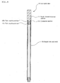
- the gas supply pipe according to the invention is explained with reference to FIG. 4 .
- FIG. 4 is a cross-sectional view of the gas supply pipe 9 for plasma treatment according to the invention.
- the gas supply pipe differs from the gas supply pipe of the above-mentioned embodiment in that it is formed of the supply pipe main body 10 composed of a metal tube (a porous stainless tube, for example), a supply channel extension member 11 composed of a non-metal tube (a fluororesin tube, for example) and a connection member 12 for connecting these members.
- the supply channel extension member 11 is provided in order to increase the length of the gas supply channel without changing the length of the metal portion of the gas supply tube 9. Due to such a configuration, the length of the metal portion of the gas supply pipe 9 is set to one-half of the wavelength of a microwave. As a result, the electric field intensity distribution along the axial direction of the container 3 is stabilized, and the gas supply channel is extended to the vicinity of the bottom portion of the container 3, thereby effectively preventing unevenness in the thickness of a deposited film.
- connection member 12 is a short tubular element (about 12 to 15 mm in length including a tube coupling portion 12a) having tube coupling portions 12a and 12b at both ends thereof.
- the connection member 12 of this embodiment has threaded tube coupling portions 12a and 12b.
- the invention is applied to this gas supply pipe 9.
- a material having a thermal expansion coefficient of 10 ⁇ 10 -6 /°C or less, for example, titanium (thermal expansion coefficient: 8.6 ⁇ 10 -6 /°C) can be selected. Due to such a configuration, peeling off of a deposited film formed on the outer surface of the connection member 12 can be effectively prevented.
- a material having a thermal expansion coefficient of 10 ⁇ 10 -6 /°C or less, ceramics (having a thermal expansion coefficient of 7.0 ⁇ 10 -6 /°C in the case of alumina), for example, can be selected. Due to such a configuration, peeling off of a deposited film formed on the outer surface of the supply channel extension member 11 can be effectively prevented.
- the supply pipe main body 10 is composed of a porous body (a sintered stainless steel pipe, for example), peeling off of a deposited film can be prevented. Therefore, in this embodiment, the supply pipe main body 10 is formed of a porous body and the supply channel extension member 11 and the connection member 12 are formed of a material having a thermal expansion coefficient of 10 ⁇ 10 -6 /°C or less.
- the supply channel extension member 11 and the connection member 12 may be formed of a porous body.
- the supply channel extension member 11 and the connection member 12 be formed of a material having a thermal expansion coefficient of 10 ⁇ 10 -6 /°C or less.
- a material having a thermal expansion coefficient of 10 ⁇ 10 -6 /°C or less can be selected.
- the material having a thermal expansion coefficient of 10 ⁇ 10 -6 /°C or less other than titanium, ceramics (alumina) with a thermal expansion coefficient of 7.0 ⁇ 10 -6 /°C, ceramics (machinable) with a thermal expansion coefficient of 8.5 ⁇ 10 -6 /°C or the like may be selected.
- the supply pipe main body 10 be provided with gas blow-off holes as in the case of the gas supply pipe 4 in the first embodiment.
- the invention can be applied to a gas supply pipe for plasma treatment which is inserted in a container held in a plasma treatment chamber to form a deposited film on the inner surface of the container by the supply of a gas for plasma treatment to the inside of the container.
- the invention can preferably be applied to a gas supply pipe for plasma treatment which is used for forming a deposited film by the plasma CVD method on the inner surface of a container such as a plastic bottle.
Landscapes
- Chemical & Material Sciences (AREA)
- Engineering & Computer Science (AREA)
- Chemical Kinetics & Catalysis (AREA)
- General Chemical & Material Sciences (AREA)
- Materials Engineering (AREA)
- Mechanical Engineering (AREA)
- Metallurgy (AREA)
- Organic Chemistry (AREA)
- Plasma & Fusion (AREA)
- Analytical Chemistry (AREA)
- Physics & Mathematics (AREA)
- Chemical Vapour Deposition (AREA)
- Details Of Rigid Or Semi-Rigid Containers (AREA)
Claims (7)
- Tuyau d'alimentation en gaz pour un traitement au plasma qui est inséré dans un récipient maintenu dans une chambre de traitement au plasma pour former un film déposé sur la surface intérieure du récipient par la fourniture d'un gaz pour le traitement au plasma sur le côté intérieur du récipient, dans lequel un élément de formation de tuyau d'alimentation qui constitue une partie ou la totalité du tuyau d'alimentation en gaz présente un coefficient de dilatation thermique de 10 x 10-6/°C, ou moins, caractérisé en ce que l'élément de formation de tuyau d'alimentation est un élément de connexion (12) qui connecte un corps principal de tuyau d'alimentation (10) et un élément d'extension de canal d'alimentation (11), dans lequel le corps principal de tuyau d'alimentation (10) est constitué d'un tube de métal, et l'élément d'extension de canal d'alimentation (11) est constitué d'un tube non métallique.
- Tuyau d'alimentation en gaz pour un traitement au plasma selon la revendication 1, dans lequel l'élément de formation de tuyau d'alimentation est composé de titane ou de céramique.
- Tuyau d'alimentation en gaz pour un traitement au plasma selon la revendication 1 ou 2, dans lequel le corps principal de tuyau d'alimentation comporte des trous de décharge de gaz.
- Tuyau d'alimentation en gaz pour un traitement au plasma selon l'une quelconque des revendications 1 à 3, dans lequel le corps principal de tuyau d'alimentation est constitué d'un tube inoxydable poreux.
- Tuyau d'alimentation en gaz pour un traitement au plasma selon l'une quelconque des revendications 1 à 4, dans lequel l'élément de connexion (12), le corps principal de tuyau d'alimentation (10) et l'élément d'extension de canal d'alimentation (11) présentent un coefficient de dilatation thermique de 10 x 10-6/°C, ou moins.
- Tuyau d'alimentation en gaz pour un traitement au plasma selon la revendication 5, dans lequel l'élément d'extension de canal d'alimentation (11) est composé de céramique qui présente un coefficient de dilatation thermique de 7,0 x 10⁻⁶/°C ou moins, ou d'une fluororésine.
- Tuyau d'alimentation en gaz pour un traitement au plasma selon l'une quelconque des revendications 1 à 6, dans lequel la longueur de la partie métallique du tuyau d'alimentation en gaz pour le traitement au plasma est fixée à la moitié de la longueur d'onde d'une micro-onde, et le canal d'alimentation en gaz s'étend jusque dans le voisinage de la partie inférieure du récipient en connectant l'élément d'extension de canal d'alimentation (11) au corps principal de tuyau d'alimentation (10) à travers l'élément de connexion (12).
Applications Claiming Priority (2)
| Application Number | Priority Date | Filing Date | Title |
|---|---|---|---|
| JP2006137896A JP5055834B2 (ja) | 2006-05-17 | 2006-05-17 | プラズマ処理用ガス供給管 |
| PCT/JP2007/059356 WO2007132676A1 (fr) | 2006-05-17 | 2007-05-02 | Tuyau d'alimentation en gaz pour traitement au plasma |
Publications (3)
| Publication Number | Publication Date |
|---|---|
| EP2019153A1 EP2019153A1 (fr) | 2009-01-28 |
| EP2019153A4 EP2019153A4 (fr) | 2010-08-04 |
| EP2019153B1 true EP2019153B1 (fr) | 2015-04-22 |
Family
ID=38693775
Family Applications (1)
| Application Number | Title | Priority Date | Filing Date |
|---|---|---|---|
| EP20070742791 Not-in-force EP2019153B1 (fr) | 2006-05-17 | 2007-05-02 | Tuyau d'alimentation en gaz pour traitement au plasma |
Country Status (5)
| Country | Link |
|---|---|
| US (1) | US20090120363A1 (fr) |
| EP (1) | EP2019153B1 (fr) |
| JP (1) | JP5055834B2 (fr) |
| CN (1) | CN101443478B (fr) |
| WO (1) | WO2007132676A1 (fr) |
Families Citing this family (6)
| Publication number | Priority date | Publication date | Assignee | Title |
|---|---|---|---|---|
| DE102009003393A1 (de) * | 2009-01-27 | 2010-07-29 | Schott Solar Ag | Verfahren zur Temperaturbehandlung von Halbleiterbauelementen |
| DE102010037401A1 (de) * | 2010-09-08 | 2012-03-08 | Ctp Gmbh | Auftragseinheit |
| JP2013163841A (ja) * | 2012-02-10 | 2013-08-22 | Jtekt Corp | 炭素膜成膜装置および炭素膜成膜方法 |
| CN103556116A (zh) * | 2013-11-05 | 2014-02-05 | 苏州市江南精细化工有限公司 | 一种用于制造特殊气瓶内派瑞林覆层的方法和装置 |
| KR20160106598A (ko) * | 2014-01-10 | 2016-09-12 | 미쓰비시 마테리알 가부시키가이샤 | 화학 증착 장치, 및 화학 증착 방법 |
| DE102017108992A1 (de) * | 2017-04-26 | 2018-10-31 | Khs Corpoplast Gmbh | Vorrichtung zur Innenbeschichtung von Behältern |
Family Cites Families (10)
| Publication number | Priority date | Publication date | Assignee | Title |
|---|---|---|---|---|
| JPH01188678A (ja) * | 1988-01-22 | 1989-07-27 | Mitsubishi Electric Corp | プラズマ気相成長装置 |
| JPH06285652A (ja) * | 1993-04-05 | 1994-10-11 | Toshiba Corp | プラズマ対向部品の接合方法 |
| US6013155A (en) * | 1996-06-28 | 2000-01-11 | Lam Research Corporation | Gas injection system for plasma processing |
| JPH10242057A (ja) * | 1997-02-25 | 1998-09-11 | Shin Etsu Handotai Co Ltd | 縦型cvd装置 |
| US6915964B2 (en) * | 2001-04-24 | 2005-07-12 | Innovative Technology, Inc. | System and process for solid-state deposition and consolidation of high velocity powder particles using thermal plastic deformation |
| JP4168671B2 (ja) * | 2002-05-31 | 2008-10-22 | 凸版印刷株式会社 | 3次元中空容器の薄膜成膜装置 |
| WO2004081254A1 (fr) * | 2003-03-12 | 2004-09-23 | Toyo Seikan Kaisha Ltd. | Dispositif de traitement au plasma micro-ondes et element de fourniture de gaz de traitement au plasma |
| JP4380185B2 (ja) | 2003-03-12 | 2009-12-09 | 東洋製罐株式会社 | プラスチックボトル内面の化学プラズマ処理方法 |
| JP2005006847A (ja) | 2003-06-18 | 2005-01-13 | Mrd:Kk | パチンコ遊技機 |
| JP3970246B2 (ja) * | 2004-01-16 | 2007-09-05 | 三菱重工業株式会社 | プラスチック容器内面へのバリヤ膜形成装置および内面バリヤ膜被覆プラスチック容器の製造方法 |
-
2006
- 2006-05-17 JP JP2006137896A patent/JP5055834B2/ja active Active
-
2007
- 2007-05-02 EP EP20070742791 patent/EP2019153B1/fr not_active Not-in-force
- 2007-05-02 WO PCT/JP2007/059356 patent/WO2007132676A1/fr active Application Filing
- 2007-05-02 US US12/226,616 patent/US20090120363A1/en not_active Abandoned
- 2007-05-02 CN CN2007800175061A patent/CN101443478B/zh not_active Expired - Fee Related
Also Published As
| Publication number | Publication date |
|---|---|
| JP2007308751A (ja) | 2007-11-29 |
| EP2019153A1 (fr) | 2009-01-28 |
| EP2019153A4 (fr) | 2010-08-04 |
| CN101443478B (zh) | 2011-07-06 |
| JP5055834B2 (ja) | 2012-10-24 |
| US20090120363A1 (en) | 2009-05-14 |
| WO2007132676A1 (fr) | 2007-11-22 |
| CN101443478A (zh) | 2009-05-27 |
Similar Documents
| Publication | Publication Date | Title |
|---|---|---|
| JP4929727B2 (ja) | プラズマ処理用ガス供給管 | |
| EP2019153B1 (fr) | Tuyau d'alimentation en gaz pour traitement au plasma | |
| JP2003054532A (ja) | 容器内面の化学プラズマ処理方法 | |
| EP2503023B1 (fr) | Élément d'alimentation en gaz pour dispositif de traitement au plasma micro-ondes | |
| US7170027B2 (en) | Microwave plasma processing method | |
| JP4311109B2 (ja) | プラスチック容器内面への蒸着膜の成膜方法 | |
| JP4548337B2 (ja) | プラスチック容器の化学プラズマ処理方法及び装置 | |
| JP4380185B2 (ja) | プラスチックボトル内面の化学プラズマ処理方法 | |
| JP2006249576A (ja) | プラズマ処理用ガス供給管 | |
| JP4379042B2 (ja) | プラズマcvd法による蒸着膜の形成に用いるプラズマ処理用ガス供給部材及び該ガス供給部材を用いての蒸着膜の形成方法 | |
| JP2004315879A (ja) | マイクロ波プラズマ処理装置及び処理方法 | |
| JP2005097678A (ja) | プラズマcvd法による化学蒸着膜 | |
| JP4873037B2 (ja) | 非耐圧性プラスチック容器 | |
| JP4232519B2 (ja) | マイクロ波プラズマ処理装置及び処理方法 | |
| JP2004332058A (ja) | マイクロ波プラズマ処理装置及び処理方法 |
Legal Events
| Date | Code | Title | Description |
|---|---|---|---|
| PUAI | Public reference made under article 153(3) epc to a published international application that has entered the european phase |
Free format text: ORIGINAL CODE: 0009012 |
|
| 17P | Request for examination filed |
Effective date: 20081024 |
|
| AK | Designated contracting states |
Kind code of ref document: A1 Designated state(s): AT BE BG CH CY CZ DE DK EE ES FI FR GB GR HU IE IS IT LI LT LU LV MC MT NL PL PT RO SE SI SK TR |
|
| AX | Request for extension of the european patent |
Extension state: AL BA HR MK RS |
|
| A4 | Supplementary search report drawn up and despatched |
Effective date: 20100702 |
|
| DAX | Request for extension of the european patent (deleted) | ||
| RAP1 | Party data changed (applicant data changed or rights of an application transferred) |
Owner name: TOYO SEIKAN KAISHA, LTD. |
|
| 17Q | First examination report despatched |
Effective date: 20130402 |
|
| GRAP | Despatch of communication of intention to grant a patent |
Free format text: ORIGINAL CODE: EPIDOSNIGR1 |
|
| INTG | Intention to grant announced |
Effective date: 20141124 |
|
| GRAS | Grant fee paid |
Free format text: ORIGINAL CODE: EPIDOSNIGR3 |
|
| GRAA | (expected) grant |
Free format text: ORIGINAL CODE: 0009210 |
|
| AK | Designated contracting states |
Kind code of ref document: B1 Designated state(s): AT BE BG CH CY CZ DE DK EE ES FI FR GB GR HU IE IS IT LI LT LU LV MC MT NL PL PT RO SE SI SK TR |
|
| REG | Reference to a national code |
Ref country code: GB Ref legal event code: FG4D |
|
| REG | Reference to a national code |
Ref country code: CH Ref legal event code: EP |
|
| REG | Reference to a national code |
Ref country code: AT Ref legal event code: REF Ref document number: 723297 Country of ref document: AT Kind code of ref document: T Effective date: 20150515 |
|
| REG | Reference to a national code |
Ref country code: IE Ref legal event code: FG4D |
|
| REG | Reference to a national code |
Ref country code: FR Ref legal event code: PLFP Year of fee payment: 9 |
|
| REG | Reference to a national code |
Ref country code: DE Ref legal event code: R096 Ref document number: 602007041154 Country of ref document: DE Effective date: 20150603 |
|
| PGFP | Annual fee paid to national office [announced via postgrant information from national office to epo] |
Ref country code: DE Payment date: 20150521 Year of fee payment: 9 |
|
| PGFP | Annual fee paid to national office [announced via postgrant information from national office to epo] |
Ref country code: FR Payment date: 20150521 Year of fee payment: 9 |
|
| REG | Reference to a national code |
Ref country code: NL Ref legal event code: VDEP Effective date: 20150422 |
|
| REG | Reference to a national code |
Ref country code: AT Ref legal event code: MK05 Ref document number: 723297 Country of ref document: AT Kind code of ref document: T Effective date: 20150422 |
|
| REG | Reference to a national code |
Ref country code: LT Ref legal event code: MG4D |
|
| PG25 | Lapsed in a contracting state [announced via postgrant information from national office to epo] |
Ref country code: NL Free format text: LAPSE BECAUSE OF FAILURE TO SUBMIT A TRANSLATION OF THE DESCRIPTION OR TO PAY THE FEE WITHIN THE PRESCRIBED TIME-LIMIT Effective date: 20150422 |
|
| PG25 | Lapsed in a contracting state [announced via postgrant information from national office to epo] |
Ref country code: ES Free format text: LAPSE BECAUSE OF FAILURE TO SUBMIT A TRANSLATION OF THE DESCRIPTION OR TO PAY THE FEE WITHIN THE PRESCRIBED TIME-LIMIT Effective date: 20150422 Ref country code: LT Free format text: LAPSE BECAUSE OF FAILURE TO SUBMIT A TRANSLATION OF THE DESCRIPTION OR TO PAY THE FEE WITHIN THE PRESCRIBED TIME-LIMIT Effective date: 20150422 Ref country code: FI Free format text: LAPSE BECAUSE OF FAILURE TO SUBMIT A TRANSLATION OF THE DESCRIPTION OR TO PAY THE FEE WITHIN THE PRESCRIBED TIME-LIMIT Effective date: 20150422 Ref country code: PT Free format text: LAPSE BECAUSE OF FAILURE TO SUBMIT A TRANSLATION OF THE DESCRIPTION OR TO PAY THE FEE WITHIN THE PRESCRIBED TIME-LIMIT Effective date: 20150824 |
|
| PG25 | Lapsed in a contracting state [announced via postgrant information from national office to epo] |
Ref country code: LV Free format text: LAPSE BECAUSE OF FAILURE TO SUBMIT A TRANSLATION OF THE DESCRIPTION OR TO PAY THE FEE WITHIN THE PRESCRIBED TIME-LIMIT Effective date: 20150422 Ref country code: GR Free format text: LAPSE BECAUSE OF FAILURE TO SUBMIT A TRANSLATION OF THE DESCRIPTION OR TO PAY THE FEE WITHIN THE PRESCRIBED TIME-LIMIT Effective date: 20150723 Ref country code: AT Free format text: LAPSE BECAUSE OF FAILURE TO SUBMIT A TRANSLATION OF THE DESCRIPTION OR TO PAY THE FEE WITHIN THE PRESCRIBED TIME-LIMIT Effective date: 20150422 Ref country code: IS Free format text: LAPSE BECAUSE OF FAILURE TO SUBMIT A TRANSLATION OF THE DESCRIPTION OR TO PAY THE FEE WITHIN THE PRESCRIBED TIME-LIMIT Effective date: 20150822 |
|
| REG | Reference to a national code |
Ref country code: CH Ref legal event code: PL |
|
| REG | Reference to a national code |
Ref country code: DE Ref legal event code: R097 Ref document number: 602007041154 Country of ref document: DE |
|
| PG25 | Lapsed in a contracting state [announced via postgrant information from national office to epo] |
Ref country code: LI Free format text: LAPSE BECAUSE OF NON-PAYMENT OF DUE FEES Effective date: 20150531 Ref country code: IT Free format text: LAPSE BECAUSE OF FAILURE TO SUBMIT A TRANSLATION OF THE DESCRIPTION OR TO PAY THE FEE WITHIN THE PRESCRIBED TIME-LIMIT Effective date: 20150422 Ref country code: CH Free format text: LAPSE BECAUSE OF NON-PAYMENT OF DUE FEES Effective date: 20150531 Ref country code: EE Free format text: LAPSE BECAUSE OF FAILURE TO SUBMIT A TRANSLATION OF THE DESCRIPTION OR TO PAY THE FEE WITHIN THE PRESCRIBED TIME-LIMIT Effective date: 20150422 Ref country code: DK Free format text: LAPSE BECAUSE OF FAILURE TO SUBMIT A TRANSLATION OF THE DESCRIPTION OR TO PAY THE FEE WITHIN THE PRESCRIBED TIME-LIMIT Effective date: 20150422 Ref country code: MC Free format text: LAPSE BECAUSE OF FAILURE TO SUBMIT A TRANSLATION OF THE DESCRIPTION OR TO PAY THE FEE WITHIN THE PRESCRIBED TIME-LIMIT Effective date: 20150422 |
|
| REG | Reference to a national code |
Ref country code: IE Ref legal event code: MM4A |
|
| PLBE | No opposition filed within time limit |
Free format text: ORIGINAL CODE: 0009261 |
|
| STAA | Information on the status of an ep patent application or granted ep patent |
Free format text: STATUS: NO OPPOSITION FILED WITHIN TIME LIMIT |
|
| PG25 | Lapsed in a contracting state [announced via postgrant information from national office to epo] |
Ref country code: PL Free format text: LAPSE BECAUSE OF FAILURE TO SUBMIT A TRANSLATION OF THE DESCRIPTION OR TO PAY THE FEE WITHIN THE PRESCRIBED TIME-LIMIT Effective date: 20150422 Ref country code: SK Free format text: LAPSE BECAUSE OF FAILURE TO SUBMIT A TRANSLATION OF THE DESCRIPTION OR TO PAY THE FEE WITHIN THE PRESCRIBED TIME-LIMIT Effective date: 20150422 Ref country code: CZ Free format text: LAPSE BECAUSE OF FAILURE TO SUBMIT A TRANSLATION OF THE DESCRIPTION OR TO PAY THE FEE WITHIN THE PRESCRIBED TIME-LIMIT Effective date: 20150422 Ref country code: RO Free format text: LAPSE BECAUSE OF NON-PAYMENT OF DUE FEES Effective date: 20150422 |
|
| GBPC | Gb: european patent ceased through non-payment of renewal fee |
Effective date: 20150722 |
|
| 26N | No opposition filed |
Effective date: 20160125 |
|
| PG25 | Lapsed in a contracting state [announced via postgrant information from national office to epo] |
Ref country code: IE Free format text: LAPSE BECAUSE OF NON-PAYMENT OF DUE FEES Effective date: 20150502 Ref country code: GB Free format text: LAPSE BECAUSE OF NON-PAYMENT OF DUE FEES Effective date: 20150722 |
|
| PG25 | Lapsed in a contracting state [announced via postgrant information from national office to epo] |
Ref country code: SI Free format text: LAPSE BECAUSE OF FAILURE TO SUBMIT A TRANSLATION OF THE DESCRIPTION OR TO PAY THE FEE WITHIN THE PRESCRIBED TIME-LIMIT Effective date: 20150422 |
|
| PG25 | Lapsed in a contracting state [announced via postgrant information from national office to epo] |
Ref country code: BE Free format text: LAPSE BECAUSE OF FAILURE TO SUBMIT A TRANSLATION OF THE DESCRIPTION OR TO PAY THE FEE WITHIN THE PRESCRIBED TIME-LIMIT Effective date: 20150422 |
|
| REG | Reference to a national code |
Ref country code: DE Ref legal event code: R119 Ref document number: 602007041154 Country of ref document: DE |
|
| PG25 | Lapsed in a contracting state [announced via postgrant information from national office to epo] |
Ref country code: MT Free format text: LAPSE BECAUSE OF FAILURE TO SUBMIT A TRANSLATION OF THE DESCRIPTION OR TO PAY THE FEE WITHIN THE PRESCRIBED TIME-LIMIT Effective date: 20150422 |
|
| REG | Reference to a national code |
Ref country code: FR Ref legal event code: ST Effective date: 20170131 |
|
| PG25 | Lapsed in a contracting state [announced via postgrant information from national office to epo] |
Ref country code: DE Free format text: LAPSE BECAUSE OF NON-PAYMENT OF DUE FEES Effective date: 20161201 Ref country code: FR Free format text: LAPSE BECAUSE OF NON-PAYMENT OF DUE FEES Effective date: 20160531 |
|
| PG25 | Lapsed in a contracting state [announced via postgrant information from national office to epo] |
Ref country code: HU Free format text: LAPSE BECAUSE OF FAILURE TO SUBMIT A TRANSLATION OF THE DESCRIPTION OR TO PAY THE FEE WITHIN THE PRESCRIBED TIME-LIMIT; INVALID AB INITIO Effective date: 20070502 Ref country code: BG Free format text: LAPSE BECAUSE OF FAILURE TO SUBMIT A TRANSLATION OF THE DESCRIPTION OR TO PAY THE FEE WITHIN THE PRESCRIBED TIME-LIMIT Effective date: 20150422 |
|
| PG25 | Lapsed in a contracting state [announced via postgrant information from national office to epo] |
Ref country code: CY Free format text: LAPSE BECAUSE OF FAILURE TO SUBMIT A TRANSLATION OF THE DESCRIPTION OR TO PAY THE FEE WITHIN THE PRESCRIBED TIME-LIMIT Effective date: 20150422 Ref country code: SE Free format text: LAPSE BECAUSE OF FAILURE TO SUBMIT A TRANSLATION OF THE DESCRIPTION OR TO PAY THE FEE WITHIN THE PRESCRIBED TIME-LIMIT Effective date: 20150422 |
|
| PG25 | Lapsed in a contracting state [announced via postgrant information from national office to epo] |
Ref country code: TR Free format text: LAPSE BECAUSE OF FAILURE TO SUBMIT A TRANSLATION OF THE DESCRIPTION OR TO PAY THE FEE WITHIN THE PRESCRIBED TIME-LIMIT Effective date: 20150422 |
|
| PG25 | Lapsed in a contracting state [announced via postgrant information from national office to epo] |
Ref country code: LU Free format text: LAPSE BECAUSE OF NON-PAYMENT OF DUE FEES Effective date: 20150502 |