EP2018985B1 - Climatisation pour véhicule automobile et procédé de contrôle correspondant - Google Patents
Climatisation pour véhicule automobile et procédé de contrôle correspondant Download PDFInfo
- Publication number
- EP2018985B1 EP2018985B1 EP08104857A EP08104857A EP2018985B1 EP 2018985 B1 EP2018985 B1 EP 2018985B1 EP 08104857 A EP08104857 A EP 08104857A EP 08104857 A EP08104857 A EP 08104857A EP 2018985 B1 EP2018985 B1 EP 2018985B1
- Authority
- EP
- European Patent Office
- Prior art keywords
- coolant
- compressor
- pressure
- air
- control unit
- Prior art date
- Legal status (The legal status is an assumption and is not a legal conclusion. Google has not performed a legal analysis and makes no representation as to the accuracy of the status listed.)
- Expired - Fee Related
Links
Images
Classifications
-
- B—PERFORMING OPERATIONS; TRANSPORTING
- B60—VEHICLES IN GENERAL
- B60H—ARRANGEMENTS OF HEATING, COOLING, VENTILATING OR OTHER AIR-TREATING DEVICES SPECIALLY ADAPTED FOR PASSENGER OR GOODS SPACES OF VEHICLES
- B60H1/00—Heating, cooling or ventilating [HVAC] devices
- B60H1/32—Cooling devices
- B60H1/3204—Cooling devices using compression
- B60H1/3205—Control means therefor
- B60H1/3217—Control means therefor for high pressure, inflamable or poisonous refrigerants causing danger in case of accidents
-
- B—PERFORMING OPERATIONS; TRANSPORTING
- B60—VEHICLES IN GENERAL
- B60H—ARRANGEMENTS OF HEATING, COOLING, VENTILATING OR OTHER AIR-TREATING DEVICES SPECIALLY ADAPTED FOR PASSENGER OR GOODS SPACES OF VEHICLES
- B60H1/00—Heating, cooling or ventilating [HVAC] devices
- B60H1/32—Cooling devices
- B60H1/3204—Cooling devices using compression
- B60H1/3205—Control means therefor
-
- F—MECHANICAL ENGINEERING; LIGHTING; HEATING; WEAPONS; BLASTING
- F25—REFRIGERATION OR COOLING; COMBINED HEATING AND REFRIGERATION SYSTEMS; HEAT PUMP SYSTEMS; MANUFACTURE OR STORAGE OF ICE; LIQUEFACTION SOLIDIFICATION OF GASES
- F25B—REFRIGERATION MACHINES, PLANTS OR SYSTEMS; COMBINED HEATING AND REFRIGERATION SYSTEMS; HEAT PUMP SYSTEMS
- F25B49/00—Arrangement or mounting of control or safety devices
- F25B49/005—Arrangement or mounting of control or safety devices of safety devices
-
- F—MECHANICAL ENGINEERING; LIGHTING; HEATING; WEAPONS; BLASTING
- F25—REFRIGERATION OR COOLING; COMBINED HEATING AND REFRIGERATION SYSTEMS; HEAT PUMP SYSTEMS; MANUFACTURE OR STORAGE OF ICE; LIQUEFACTION SOLIDIFICATION OF GASES
- F25B—REFRIGERATION MACHINES, PLANTS OR SYSTEMS; COMBINED HEATING AND REFRIGERATION SYSTEMS; HEAT PUMP SYSTEMS
- F25B9/00—Compression machines, plants or systems, in which the refrigerant is air or other gas of low boiling point
- F25B9/002—Compression machines, plants or systems, in which the refrigerant is air or other gas of low boiling point characterised by the refrigerant
- F25B9/006—Compression machines, plants or systems, in which the refrigerant is air or other gas of low boiling point characterised by the refrigerant the refrigerant containing more than one component
Definitions
- the invention relates to an air conditioning system for a motor vehicle having a coolant circuit formed at least from a compressor for compressing the coolant, a condenser for cooling the compressed coolant, an expansion device for reducing the pressure of the coolant and an evaporator for evaporating the coolant, and a method for operating an air conditioning system ,
- the air conditioner makes it possible to provide a cooling medium with a low temperature, which is supplied to a heat exchanger and used there for cooling ambient air or indoor air of a motor vehicle which has a high temperature. The cooled air is then fed to an interior of the motor vehicle in order to allow cooling there, in particular a temperature control to a predefinable target temperature.
- the fluorocarbon 1,1,1,2-tetrafluoroethane
- R134a chlorofluorocarbons
- the object of the invention is to provide an air conditioning system that can be easily adapted to different national legal regulations.
- the air conditioning system can be operated with at least two different cooling means, without filling the refrigerant circuit with one or the other coolant deep changes in the coolant circuit or the control unit must be made
- the at least two different coolants to which the controller is configured have similar characteristics such as density, heat transfer properties, viscosity, and heat capacity.
- the controller is programmable and can be programmed after filling with a coolant with the coolant-specific characteristics, maps or calculation algorithms.
- the expansion device in the coolant circuit is designed as a capillary tube ("orifice"), since such a capillary tube allows use of a wide range of coolants, without having to make changes to the capillary tube for the various coolants.
- the control unit is connected to the compressor and is set up for a coolant-dependent influencing of a compressor pressure and / or a compressor output.
- Compressor pressure is the maximum pressure that can be achieved by compressing the refrigerant in the compressor. Since different coolants can also be compressed with different degrees of ease and different pressure differences in the expansion device must be achieved for these different coolants in order to achieve substantially the same cooling performance for the air conditioning system, the compressor pressure can be adjusted in an adjustable compressor, in particular by adjusting the compressor stroke. be specified.
- the power provided to the compressor can be controlled or regulated by the control device by either throttling the power to be provided or by the compressor being operated only temporarily, ie having a duty cycle of less than 100%.
- a controllable clutch can be provided between the internal combustion engine and the compressor, which can be influenced by the control unit in order to effect a reduction in power by slippage or a disconnection of the power supply by disengaging.
- a temperature sensor connected to the control unit is attached to the evaporator, and that the control unit is set up to influence the compressor pressure and / or the compressor output as a function of the coolant and in dependence on a temperature signal of the temperature sensor.
- the controller may in the presence of too low evaporator temperature, which could lead to icing of the evaporator, a power reduction or shutdown of the compressor, so that temporarily no refrigerant is expanded in the evaporator.
- the evaporator with the help of ambient air or indoor air of the motor vehicle can be brought back to a temperature at which icing can be excluded.
- a different influence of the compressor pressure and / or the compressor power takes place.
- a pressure sensor is mounted, and that the control device is arranged for influencing the compressor pressure and / or the compressor power in dependence on the coolant and in response to a pressure signal of the pressure sensor.
- the pressure signal determined by the pressure sensor allows the control unit to draw conclusions about the temperature at the evaporator in the knowledge of the coolant used and possibly make a reduction in performance or a pressure reduction at the compressor when icing of the evaporator threatens.
- the pressure sensor may be associated with the suction side or the pressure side of the compressor.
- control unit is connected to a cooling device attached to the condenser and is set up to control the cooling device as a function of the coolant or the coolant and a temperature at the evaporator and / or a pressure at the compressor.
- the condenser is a heat exchanger in which the coolant heated by the compressor flows through the compression and is surrounded by ambient air to cause cooling of the refrigerant.
- the ambient air is directed with a designed as a fan cooling device to the condenser.
- the cooling device is controlled as a function of the coolant used, optionally including the temperature of the evaporator and / or the pressure at the compressor in order to bring about a sufficient additional cooling for the coolant in the condenser can.
- the expansion device has an exchangeable capillary tube, which is adapted to the coolant.
- the capillary tube in the expander is also referred to as an "orifice" and is a nozzle or restrictor restricting a volume flow of the refrigerant and thus ensuring that between the output side of the compressor and the capillary tube, a high pressure prevails in the refrigerant circuit, while between the capillary tube and the inlet side of the compressor is at a lower pressure.
- the coolant Due to the throttling effect of the capillary tube and the resulting pressure reduction for the coolant and by the provision of heat at the evaporator, the coolant is evaporated and thus withdraws the ambient air or the indoor air flowing around the evaporator, a predetermined amount of heat. As a result, the ambient air or indoor air is cooled and the coolant flows substantially in the gaseous state in the direction of the input side of the compressor.
- the throttling properties of the capillary tube are determined essentially by its inner diameter and by its length, which can be expressed in combination as a normalized effective cross-section. The requirements for the effective cross section may be different between the different coolants, so that an adaptation of the coolant circuit to different coolant can be made by replacing the simply constructed capillary tube.
- control unit at least two different characteristics or maps or calculation algorithms for controlling the compressor and / or a fan for the capacitor in dependence on the coolant and / or a pressure on Compressor and / or a temperature at the evaporator.
- a characteristic curve is a two-dimensional representation of a relationship between a first parameter, for example a power output to the compressor or a duty factor for the fan on the condenser, and a second parameter, for example the pressure at the compressor or the temperature at the condenser.
- a map is a three- or more-dimensional representation of relationships between at least three parameters.
- An algorithm is a calculation formula that can be used to calculate at least one parameter knowing another parameter. According to the invention, the control device can be tuned by selecting one of the two characteristics, maps or algorithms in an advantageous manner to a first or to a second coolant.
- control unit is set up in such a way that it can determine a coolant introduced into the coolant circuit on the basis of stored correlations of a pressure at the compressor and a temperature at the evaporator, in particular taking into account further parameters such as an ambient temperature.
- the air conditioner can be operated in an optimum operating condition after being filled with an approved coolant, even if the coolant is other than the originally filled coolant. This case can occur, in particular, when new coolant is introduced as part of a maintenance of the air conditioning system, which is not identical with the originally filled coolant either for reasons of availability or due to changed legal requirements.
- a change in the coolant may also be due to degeneration effects of the originally filled coolant or due to a mixing of coolants, as may occur in particular when refilling the air conditioning.
- a selective escape of coolant components can also lead to a change in the properties of the coolant, which can be compensated in part or completely by the inventive design of the controller by the corresponding parameters or the underlying algorithms are aligned in the control unit.
- At least one freely programmable memory area is provided in the control unit, which enables storage of at least one characteristic curve and / or characteristic map and / or one or more correction factors and / or a calculation algorithm.
- the compressor has an adjustable stroke, and that the control device is set up for an adjustment of the compressor stroke.
- an accumulator for separating liquid and gaseous coolant is provided.
- the accumulator prevents not completely evaporated refrigerant from the compressor is sucked in and there leads to damage.
- control unit is connected to a compressor mounted on the adjustable pressure control valve, which is provided for influencing a target temperature at the evaporator.
- the pressure regulating valve is provided for the regulation of a suction pressure target value, which can be regulated in particular by controlling the pressure regulating valve with a PWM signal (pulse width modulation signal) of the control unit.
- PWM signal pulse width modulation signal
- To the suction pressure target value correlates depending on the refrigerant used Target temperature at the evaporator; This is set in particular by a PID controller provided in the control unit (proportional-integral-derivative controller) for the pressure regulating valve.
- a heat exchanger is arranged between an outlet port of the condenser and an inlet port of the compressor. This allows a preheating of the refrigerant sucked by the compressor and an additional cooling of the coolant before entering the expansion device. Thus, the efficiency of the air conditioner can be increased for certain coolants.
- a method for operating an air conditioning system in which, in a rest state of the air conditioner, a static pressure of a coolant and a quiescent temperature of the coolant and / or an ambient temperature are determined.
- the determined values for the static pressure and the quiescent temperature and / or the ambient temperature can be stored in a table of values and / or fed into a control unit and serve as a basis for calculating the characteristic properties of the components of the air conditioner and / or the coolant used in the air conditioning ,
- the idle state of the air conditioning system can be determined in particular via the engine temperature of the motor vehicle in which the air conditioning system is installed, which can be interrogated via a bus system and which must be below a predefinable threshold value in order to be able to make a proper determination of the static pressure.
- an operating pressure of a coolant and an operating temperature of the coolant and / or an ambient temperature are determined.
- the operating pressure and the operating temperature are also stored in a table of values and / or fed into a control unit and serve as the quiescent temperature and the static pressure of the characterization of properties of the air conditioning.
- a cooling capacity of a cooling device which is provided for cooling a capacitor, is set by a control unit and the operating pressure of the coolant is determined in dependence on the set cooling capacity.
- the cooling capacity of the cooling device which may be formed, for example, as the condenser associated fan, continuously or stepwise increased from a minimum cooling capacity to a maximum cooling capacity and determined in continuous or incremental measurement of the operating pressure of the coolant.
- the determined value pairs (operating pressure correlated with cooling capacity) are stored in a value table.
- a ventilation device for discharging a provided by an evaporator cooling capacity is set by the control unit to a, in particular minimum, air mass flow and the operating pressure of the coolant is determined in dependence on the set air mass flow.
- the ventilation device determines, via the air mass flow and as a function of the temperature of the supplied air, how much energy is provided at the evaporator for evaporating the coolant. While at a low air temperature (in particular a low interior temperature of the motor vehicle equipped with the air conditioning system) and a minimal amount of energy is provided at the evaporator to evaporate the coolant, a high amount of energy is provided at the evaporator at high air temperature and maximum air mass flow.
- a threshold can be determined with known air mass flow, from which the operating pressure of the coolant no longer decreases, even if the cooling capacity of the cooling device, which serves to cool the capacitor is further increased.
- the value share from the cooling device supplied cooling power, the air mass flow and the air temperature at the evaporator and the self-adjusting, minimum refrigerant pressure is stored in a look-up table and / or fed into a control unit.
- the ventilation device may in particular be a fan, which serves for the circulation of air in an interior of the motor vehicle and / or for the provision of fresh air into the interior of the motor vehicle.
- the quiescent pressure of the coolant, the operating pressure of the coolant, in particular as a function of the cooling capacity of a cooling device and / or in dependence on the air mass flow of the ventilation device, the operating temperature of the coolant and / or the ambient temperature the control unit are provided to determine at least one characteristic curve of the coolant, in particular a vapor pressure curve of the coolant.
- the characteristic of the coolant may be at each restart of the motor vehicle equipped with the air conditioner, or at random or predetermined intervals, and serves to detect changes in the characteristics of the coolant.
- Such property changes may occur when highly volatile components of the refrigerant volatilize when a second coolant is added to a first coolant when servicing, or when components of the coolant change over time, such as decompose.
- an advantageous adaptation of the operating mode of the air conditioning system can be carried out in order to achieve maximum cooling capacity within the framework of the present boundary conditions with minimal energy input.
- a diagnosis for the cooling capability of the respective currently present coolant composition can be made and notification of the user of the air conditioning system can be provided if a minimum cooling capability is undershot.
- control unit an adjustment of a suction pressure and / or an evaporator temperature by influencing a power of a compressor, in particular by influencing a duty cycle of the compressor or by driving a compressor associated pressure control valve, in dependence on the determined characteristic of the Coolant makes. This ensures energy-efficient operation of the air conditioning system depending on the composition of the coolant.
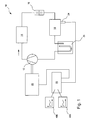
- a motor vehicle air conditioner 10 includes a refrigerant circuit having a compressor 12 for compressing the refrigerant, a condenser 14 for cooling the compressed refrigerant; an expansion device designed as a throttle capillary 16 for reducing the pressure of the coolant and an evaporator 18 for evaporating the coolant. Furthermore, the coolant circuit is associated with a control unit 20 which is connected to an electric motor 22 which is provided for driving the compressor 12. The control unit 20 is also connected to a temperature sensor 24 attached to the evaporator 18, which provides a temperature signal which is proportional to the temperature at the evaporator 18.
- the compressor 12 has a fixed, non-adjustable stroke, so that an adjustment of the coolant pressure in the coolant circuit by a cyclic or acyclic compression of coolant must be achieved. Since no pressure sensor for the coolant is provided in the illustrated embodiment, the refrigerant pressure to be provided by the compressor 12 is determined by means of the Temperature sensor 24 at the evaporator 18 using one of at least two deposited in the control unit 20, coolant-dependent characteristics 40a, 40b determined, which are assigned schematically as graphs to the control unit 20. From the characteristic curve, it is also possible to derive with the aid of a calculation algorithm stored in the control unit, with which power supply and / or switch-on duration of the electric motor 22 the desired coolant pressure can be achieved.
- the compressor is coupled via a shiftable clutch and a V-belt to the crankshaft of an internal combustion engine.
- the switchable clutch is controlled by the control unit and allows the compressor to be switched on or off as required to control a medium compressor output.
- the refrigerant is compressed while also being heated by the energy supply during compression.
- a portion of the supplied heat is removed from the coolant in the condenser 14, which serves as a heat exchanger with the ambient air, so that it now has a high pressure and a reduced energy content and is converted into the liquid state of aggregation.
- the throttle capillary 16, which is arranged downstream of the condenser 14, is essentially adapted to the properties of the coolant used with regard to its inner diameter and its length, so that it represents a predeterminable flow resistance for the liquid coolant. Since the compressor 12 can deliver more coolant than can flow through the throttle capillary 16, a coolant-dependent pressure builds up between the compressor 12 and the throttle capillary 16.
- the coolant-dependent pressure is determined in particular by the vapor pressure of the coolant and its viscosity in the liquid state and is stored in the corresponding characteristic curve 40 a, 40 b in the control unit 20.
- the refrigerant flowing through the throttle capillary 16 enters a low pressure region and expands. Due to the expansion and the heat supply to the evaporator 18, the coolant changes-at least substantially-from the liquid to the gaseous state, wherein a considerable amount of energy is required for evaporation. This amount of energy is the ambient air in the area withdrawn from the evaporator 18, the air is thus cooled and can be supplied to an interior (not shown) of a motor vehicle.
- the now at least substantially gaseous coolant flows through an accumulator 26 to separate any liquid components present, and is then returned to the compressor 12 to be recompressed and liquefied.
- the controller 20 can draw conclusions on what cooling needs currently exists and whether the compressor 12 must compress additional refrigerant or not.
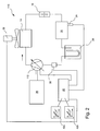
- the embodiment of the air conditioner 110 according to the Fig. 2 differs from the embodiment according to Fig. 1 in that the internal combustion engine 28 of a motor vehicle, not shown, is used to drive the compressor 112, which is designed as an adjustable compressor 112 with an externally adjustable control device 20 and an adjusting device not shown adjustable stroke and thereby an influence on the in the coolant circuit prevailing coolant pressure allows.
- the control unit 20 is connected to a pressure sensor 30, which is arranged in the coolant circuit between the accumulator 26 and the compressor 112 and which enables a determination of the pressure of the gaseous coolant.
- a pressure sensor is arranged on the high pressure side at the outlet of the compressor or downstream of the condenser, in addition or as an alternative to the arranged between the accumulator and the compressor pressure sensor.
- the controller 20 is connected to a fan 32 associated with the condenser 14 to effect improved heat exchange of the condenser 14 with the ambient air.
- a fan 32 associated with the condenser 14 to effect improved heat exchange of the condenser 14 with the ambient air.
- the control unit 20 for each of a plurality of coolant associated multi-dimensional maps 42a, 42b are deposited, in which relationships between the pressure of the coolant at the pressure sensor 30, the temperature at the evaporator 18 and to be provided by the compressor 112 Coolant pressure and the air to be provided by the fan 32 air flow to cool the capacitor are held.
- the maps 42a, 42b thus provide the signal levels necessary for driving the variable displacement compressor 112 and the fan 32 to ensure efficient operation of the air conditioning system 110.
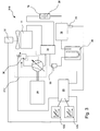
- a heat exchanger 34 is provided, which allows a heat flow between the output terminal of the capacitor 14 and the input terminal of the compressor 212.
- a pressure control valve 36 which is connected downstream of the compressor 212 and can be actuated by the control unit 20, regulates the pressure of the coolant compressed by the compressor 212 and thus also the suction pressure of the coolant drawn in by the compressor 212 by adjusting the stroke of the adjustable compressor 212. This is done by presetting a pressure value from the control unit 20 to the pressure control valve 36, which in turn influences the compressor 212 via a control line.
- an adjustment of the evaporator temperature can be made via the setting of the pressure control valve 36 as a function of the coolant used.
- the throttle tube 38 used in the throttle capillary 16 is designed to be interchangeable in order to make an advantageous adaptation to different coolant.
- a plurality of multi-dimensional maps 42a, 42b are deposited, which on the from the embodiment of the Fig. 2 Known control of the compressor 212 and the fan 32 also allow a control of the pressure control valve 36 to cause a favorable operation of the air conditioner 10 can.
- an electronically adjustable by the control unit expansion valve provided by means of which the throttle effect can be adjusted to the requirements of the air conditioning.
- corresponding characteristic curves for the expansion valve are stored in the control unit, indicating a relationship between the composition and describe the properties of the coolant and the respective required throttling.
- An adaptation of the air conditioning systems 10, 110, 210 according to the embodiments of Fig. 1 to 3 to different coolant can be done by selecting a stored in the control unit 20 characteristic or a characteristic field or a calculation algorithm, for example, at the end of a production process in the programming of the other control units of the motor vehicle.
- the control unit 20 can be programmed with a coolant having the corresponding characteristic curves, characteristic diagrams or calculation algorithms.
- control unit 20 makes an independent detection of the coolant based on the temperatures and pressures occurring in operation in the coolant circuit and then uses the characteristic values for the operation of the air conditioning system provided for the corresponding coolant.
Claims (18)
- Installation de climatisation (10, 110, 210) pour un véhicule automobile,
comprenant un circuit de refroidissement formé au moins à partir des composants suivantes :- un compresseur (12, 112, 212) pour comprimer le réfrigérant,- un condenseur (14) pour refroidir le réfrigérant comprimé ;- un dispositif d'expansion (16) pour la réduction de pression du réfrigérant et- un évaporateur (18) pour l'évaporation du réfrigérant,caractérisée en ce que
l'on prévoit un appareil de commande (20) qui est connecté à au moins l'un des composants de circuit de refroidissement et qui est prévu pour adapter une caractéristique de fonctionnement des composants du circuit de refroidissement à au moins deux réfrigérants différents, l'installation de climatisation détectant automatiquement le réfrigérant qu'elle utilise par le fait que- dans un état de repos de l'installation de climatisation, une pression de repos du réfrigérant et une température de repos du réfrigérant et/ou une température ambiante sont détectées, les valeurs détectées pour la pression de repos et la température de repos et/ou la température ambiante étant consignées dans un tableau de valeurs, et/ou étant saisies dans l'appareil de commande et servant de base de calcul pour déterminer le réfrigérant utilisé dans l'installation de climatisation et/ou- l'appareil de commande (20) est réalisé de telle sorte qu'il puisse déterminer un réfrigérant introduit dans le circuit de refroidissement à l'aide de corrélations mémorisées d'une pression au niveau du compresseur (12, 112, 212) et d'une température au niveau de l'évaporateur (18), en particulier en tenant compte d'autres paramètres tels qu'une température ambiante. - Installation de climatisation selon la revendication 1,
caractérisée en ce que
l'appareil de commande (20) est connecté au compresseur (12, 112, 212) et est prévu pour influencer, en fonction du réfrigérant, une pression du compresseur et/ou une puissance du compresseur. - Installation de climatisation selon la revendication 1 ou 2,
caractérisée en ce que
l'on prévoit au niveau de l'évaporateur (18) un capteur de température (24) connecté à l'appareil de commande (20), et en ce que l'appareil de commande (20) est prévu pour influencer la pression du compresseur et/ou la puissance du compresseur en fonction du réfrigérant et en fonction d'un signal de température du capteur de température (24). - Installation de climatisation selon l'une quelconque des revendications 1 à 3,
caractérisée en ce que
l'on prévoit au niveau du compresseur (12, 112, 212) en particulier du côté aspiration, un capteur de pression (30) et en ce que l'appareil de commande (20) est prévu pour influencer la pression du compresseur et/ou la puissance du compresseur en fonction du réfrigérant et en fonction d'un signal de pression du capteur de pression (30). - Installation de climatisation selon l'une quelconque des revendications 1 à 4,
caractérisée en ce que
l'appareil de commande (20) est connecté à un dispositif de refroidissement (32) monté au niveau du condenseur (14), et est prévu pour commander le dispositif de refroidissement (32) en fonction du réfrigérant ou du réfrigérant et d'une température au niveau de l'évaporateur (18) et/ou d'une pression au niveau du compresseur (12, 112, 212). - Installation de climatisation selon l'une quelconque des revendications 1 à 5,
caractérisée en ce que
le dispositif d'expansion (16) présente un tube capillaire interchangeable (38) qui est adapté au réfrigérant. - Installation de climatisation selon l'une quelconque des revendications 1 à 6,
caractérisée en ce que
l'appareil de commande (20) présente au moins deux courbes caractéristiques différentes (40a, 40b) ou champs caractéristiques (42a, 42b) différents ou algorithmes de calcul différents pour une commande du compresseur (12, 112), et/ou d'un ventilateur (32) pour le condenseur (14) en fonction du réfrigérant et/ou d'une pression au niveau du compresseur (12, 112) et/ou d'une température au niveau de l'évaporateur (18). - Installation de climatisation selon l'une quelconque des revendications 1 à 7,
caractérisée en ce que
l'appareil de commande (20) est prévu de telle sorte qu'il puisse détecter un réfrigérant introduit dans un circuit de refroidissement à l'aide de corrélations mémorisées d'une pression au niveau du compresseur (12, 112, 212) et d'une température au niveau de l'évaporateur (18), en particulier en tenant compte d'autres paramètres tels qu'une température ambiante. - Installation de climatisation selon l'une quelconque des revendications 1 à 8,
caractérisée en ce que
le compresseur (12, 112, 212) présente une course ajustable et en ce que l'appareil de commande (20) est prévu pour ajuster la course du compresseur. - Installation de climatisation selon l'une quelconque des revendications 1 à 9,
caractérisée en ce
qu'un accumulateur (26) est prévu pour séparer le réfrigérant liquide du réfrigérant gazeux. - Installation de climatisation selon l'une quelconque des revendications 1 à 10,
caractérisée en ce que
l'appareil de commande (20) est connecté à une soupape de régulation de pression (36) ajustable montée sur le compresseur (12, 112, 212) qui est prévue pour influencer une température cible au niveau de l'évaporateur (18). - Installation de climatisation selon l'une quelconque des revendications 1 à 11,
caractérisée en ce que
l'on dispose un échangeur de chaleur (34) entre un raccord de sortie du condenseur (14) et un raccord d'entrée du compresseur (12, 112, 212). - Procédé pour faire fonctionner une installation de climatisation selon l'une quelconque des revendications 1 à 12,
caractérisé en ce que
dans un état de repos de l'installation de climatisation, une pression de repos d'un réfrigérant et une température de repos du réfrigérant et/ou une température ambiante sont déterminées. - Procédé selon la revendication 13,
caractérisé en ce que
dans un état de fonctionnement de l'installation de climatisation, une pression de fonctionnement d'un réfrigérant et une température de fonctionnement du réfrigérant et/ou une température ambiante sont déterminées. - Procédé selon la revendication 14,
caractérisé en ce que
dans l'état de fonctionnement de l'installation de climatisation, une puissance de refroidissement d'un dispositif de refroidissement (32), qui est prévu pour refroidir un condenseur (14), est ajustée par un appareil de commande (20) et la pression de fonctionnement du réfrigérant est déterminée en fonction de la puissance de refroidissement ajustée. - Procédé selon la revendication 15,
caractérisé en ce
qu'un dispositif de ventilation pour l'évacuation d'une puissance de refroidissement fournie par un évaporateur (18) est ajusté par l'appareil de commande (20) à un débit massique d'air, notamment minimal, et la pression de fonctionnement du réfrigérant est déterminée en fonction du débit massique d'air ajusté. - Procédé selon l'une quelconque des revendications 14 à 16,
caractérisé en ce que
la pression de repos du réfrigérant, la pression de fonctionnement du réfrigérant déterminée notamment en fonction de la puissance de refroidissement d'un dispositif de refroidissement (32) et/ou en fonction du débit massique d'air du dispositif de ventilation, la température de fonctionnement du réfrigérant et/ou la température ambiante sont fournies au niveau de l'appareil de commande (20), afin de déterminer au moins une courbe caractéristique du réfrigérant, en particulier une courbe de pression de vapeur du réfrigérant. - Procédé selon la revendication 17,
caractérisé en ce que
l'appareil de commande (20) effectue un ajustement d'une pression d'aspiration et/ou d'une température de l'évaporateur en influençant une puissance d'un compresseur (12, 112, 212), en particulier en influençant une durée d'enclenchement du compresseur (12, 112, 212), ou en commandant une soupape de régulation de pression (36) associée au compresseur (2, 112, 212), en fonction de la courbe caractéristique du réfrigérant déterminée.
Applications Claiming Priority (1)
| Application Number | Priority Date | Filing Date | Title |
|---|---|---|---|
| DE102007034821A DE102007034821A1 (de) | 2007-07-26 | 2007-07-26 | Klimaanlage für ein Kraftfahrzeug sowie Verfahren zu deren Betrieb |
Publications (3)
| Publication Number | Publication Date |
|---|---|
| EP2018985A2 EP2018985A2 (fr) | 2009-01-28 |
| EP2018985A3 EP2018985A3 (fr) | 2010-05-19 |
| EP2018985B1 true EP2018985B1 (fr) | 2011-05-25 |
Family
ID=39796913
Family Applications (1)
| Application Number | Title | Priority Date | Filing Date |
|---|---|---|---|
| EP08104857A Expired - Fee Related EP2018985B1 (fr) | 2007-07-26 | 2008-07-24 | Climatisation pour véhicule automobile et procédé de contrôle correspondant |
Country Status (4)
| Country | Link |
|---|---|
| US (1) | US8555661B2 (fr) |
| EP (1) | EP2018985B1 (fr) |
| CN (1) | CN101353006B (fr) |
| DE (1) | DE102007034821A1 (fr) |
Families Citing this family (8)
| Publication number | Priority date | Publication date | Assignee | Title |
|---|---|---|---|---|
| DE102009027065A1 (de) | 2009-06-22 | 2010-12-23 | Ford Global Technologies, LLC, Dearborn | Klimaanlage für ein Kraftfahrzeug, sowie Verfahren zum Betreiben derselben |
| JP5316321B2 (ja) * | 2009-09-02 | 2013-10-16 | 株式会社デンソー | 車両用空調装置 |
| JP2011068190A (ja) * | 2009-09-24 | 2011-04-07 | Denso Corp | 車両用空調制御装置 |
| DE102012222594B4 (de) | 2012-12-10 | 2018-05-17 | Bayerische Motoren Werke Aktiengesellschaft | Verfahren zum Betreiben eines Kältemittelkreislaufs als Wärmepumpe sowie als Wärmepumpe betreibbarer Kältemittelkreislauf |
| CN105444369B (zh) * | 2014-08-14 | 2019-07-19 | 广州汽车集团股份有限公司 | 汽车空调系统 |
| US9869223B2 (en) * | 2014-08-22 | 2018-01-16 | GM Global Technology Operations LLC | Flexible engine metal warming system and method for an internal combustion engine |
| CN106314065B (zh) * | 2015-06-15 | 2018-10-16 | 比亚迪股份有限公司 | 汽车空调系统及其控制方法、汽车 |
| GB2530165A (en) * | 2015-08-06 | 2016-03-16 | Daimler Ag | Method of operating an air conditioning device and air conditioning device |
Family Cites Families (15)
| Publication number | Priority date | Publication date | Assignee | Title |
|---|---|---|---|---|
| US4745767A (en) * | 1984-07-26 | 1988-05-24 | Sanyo Electric Co., Ltd. | System for controlling flow rate of refrigerant |
| AU633766B2 (en) * | 1991-01-15 | 1993-02-04 | Spx Corporation | Refrigerant handling system with liquid refrigerant and multiple refrigerant capabilities |
| US5231842A (en) | 1991-01-15 | 1993-08-03 | Spx Corporation | Refrigerant handling system with liquid refrigerant and multiple refrigerant capabilities |
| US5203179A (en) * | 1992-03-04 | 1993-04-20 | Ecoair Corporation | Control system for an air conditioning/refrigeration system |
| US5231742A (en) * | 1992-06-08 | 1993-08-03 | Macbain Kathleen E | Hand twining looms |
| US5289692A (en) * | 1993-01-19 | 1994-03-01 | Parker-Hannifin Corporation | Apparatus and method for mass flow control of a working fluid |
| DE19935269C1 (de) * | 1999-07-27 | 2001-01-25 | Daimler Chrysler Ag | Verfahren zur Überwachung des Kältemittelfüllstandes in einer Kälteanlage |
| IT1320635B1 (it) * | 2000-09-12 | 2003-12-10 | Fiat Ricerche | Procedimento e sistema per il monitoraggio dello stato di carica di un impianto di climatizzazione di un autoveicolo. |
| US20050092002A1 (en) * | 2000-09-14 | 2005-05-05 | Wightman David A. | Expansion valves, expansion device assemblies, vapor compression systems, vehicles, and methods for using vapor compression systems |
| US20030057396A1 (en) * | 2001-09-25 | 2003-03-27 | Cawley Richard E. | Replacement refrigerant for R410A |
| DE102004002174B4 (de) * | 2004-01-16 | 2010-09-16 | Audi Ag | Verfahren und Regeleinrichtung zum Regeln eines Verdichters |
| JP2005225432A (ja) * | 2004-02-16 | 2005-08-25 | Sanyo Electric Co Ltd | 車両用空調システム |
| DE102004024579B3 (de) * | 2004-05-18 | 2006-01-19 | Daimlerchrysler Ag | Vorrichtung und Verfahren zur Füllstandsüberwachung eines Kältemittelkreislaufs einer Fahrzeugklimaanlage |
| DE602004014503D1 (de) | 2004-10-14 | 2008-07-31 | Ford Global Tech Llc | Verfahren zum Schätzen des Leistungsverbrauchs eines Kältemittelkreislaufkompressors in einem Kraftfahrzeug |
| EP1650067B1 (fr) * | 2004-10-21 | 2008-07-16 | Halla Climate Control Corporation | Procédé de régulation d'une installation de climatisation pour véhicule |
-
2007
- 2007-07-26 DE DE102007034821A patent/DE102007034821A1/de not_active Ceased
-
2008
- 2008-07-22 CN CN2008101320529A patent/CN101353006B/zh not_active Expired - Fee Related
- 2008-07-24 US US12/179,317 patent/US8555661B2/en not_active Expired - Fee Related
- 2008-07-24 EP EP08104857A patent/EP2018985B1/fr not_active Expired - Fee Related
Also Published As
| Publication number | Publication date |
|---|---|
| EP2018985A3 (fr) | 2010-05-19 |
| EP2018985A2 (fr) | 2009-01-28 |
| CN101353006A (zh) | 2009-01-28 |
| CN101353006B (zh) | 2012-11-28 |
| US20090049848A1 (en) | 2009-02-26 |
| US8555661B2 (en) | 2013-10-15 |
| DE102007034821A1 (de) | 2009-01-29 |
Similar Documents
| Publication | Publication Date | Title |
|---|---|---|
| EP2018985B1 (fr) | Climatisation pour véhicule automobile et procédé de contrôle correspondant | |
| DE102005028405B4 (de) | Überkritisches Wärmepumpenkreissystem | |
| EP0701096B1 (fr) | Procédé de fonctionnement d'une installation productrice de froid pour la climatisation de véhicules et installation productrice de froid pour sa mise en oeuvre | |
| DE102006029973B4 (de) | Ejektorkreislaufsystem | |
| EP1057669B1 (fr) | Système de refroidissement à compression à entraínement électrique avec cycle de procédé supercritique | |
| DE102005007321B4 (de) | Ejektorpumpenkreis mit mehreren Verdampfapparaten | |
| EP3697635B1 (fr) | Procédé servant à faire fonctionner un circuit frigorifique ainsi qu'une installation de réfrigération de véhicule | |
| DE3215997C2 (fr) | ||
| DE60309267T2 (de) | Regelungsverfahren für einen Kondensatorlüfter zur Senkung des Energieverbrauchs einer Fahrzeugklimaanlage | |
| DE102014111971B4 (de) | Klimaanlage für ein Fahrzeug | |
| DE10220168A1 (de) | Fahrzeugklimaanlage und Regelungsverfahren einer solchen | |
| DE102013114374B4 (de) | Verfahren zur Drehzahlregelung bei einem Verdichter mit variabler Drehzahl | |
| DE102017011430A1 (de) | Kühlsystem für eine elektrische Antriebseinheit für ein Fahrzeug | |
| DE10347748A1 (de) | Mehrfachzonen-Temperatursteuersystem | |
| DE60118588T2 (de) | Fahrzeugklimaanlage unter verwendung eines überkritischen kreislaufes | |
| DE102006047415A1 (de) | Fahrzeug-Klimaanlage mit Verstellkompressor | |
| DE10203772A1 (de) | Klimaanlage mit Heizfunktion und Verfahren zum Betrieb einer Klimaanlage mit Heizfunktion | |
| EP1554142A1 (fr) | Procede de regulation de la temperature d'evaporation d'une installation de climatisation | |
| DE102013102879B4 (de) | Kompressor mit Anpassung der Gaseintrittstemperatur und Verfahren zum Betreiben dieses Kompressors | |
| DE112014002751T5 (de) | Klimaanlagen-System für ein Fahrzeug und Verfahren zu dessen Steuerung | |
| DE102004029166A1 (de) | Verfahren und Vorrichtung zur Regelung eines Kältemittelkreislaufs einer Klimaanlage für ein Fahrzeug | |
| DE102015010593B4 (de) | Betriebsverfahren für eine Kälteanlage und zugehörige Kälteanlage | |
| DE102019119751B3 (de) | Verfahren zum Betreiben eines Kältekreislaufs eines Kraftfahrzeugs und Kältekreislauf | |
| DE102013203240A1 (de) | Kältemaschine und Verfahren zum Betreiben einer Kältemaschine | |
| DE102007039296A1 (de) | Wärmepumpenanlage |
Legal Events
| Date | Code | Title | Description |
|---|---|---|---|
| PUAI | Public reference made under article 153(3) epc to a published international application that has entered the european phase |
Free format text: ORIGINAL CODE: 0009012 |
|
| AK | Designated contracting states |
Kind code of ref document: A2 Designated state(s): AT BE BG CH CY CZ DE DK EE ES FI FR GB GR HR HU IE IS IT LI LT LU LV MC MT NL NO PL PT RO SE SI SK TR |
|
| AX | Request for extension of the european patent |
Extension state: AL BA MK RS |
|
| PUAL | Search report despatched |
Free format text: ORIGINAL CODE: 0009013 |
|
| AK | Designated contracting states |
Kind code of ref document: A3 Designated state(s): AT BE BG CH CY CZ DE DK EE ES FI FR GB GR HR HU IE IS IT LI LT LU LV MC MT NL NO PL PT RO SE SI SK TR |
|
| AX | Request for extension of the european patent |
Extension state: AL BA MK RS |
|
| 17P | Request for examination filed |
Effective date: 20101119 |
|
| AKX | Designation fees paid |
Designated state(s): DE FR GB |
|
| GRAP | Despatch of communication of intention to grant a patent |
Free format text: ORIGINAL CODE: EPIDOSNIGR1 |
|
| RIC1 | Information provided on ipc code assigned before grant |
Ipc: B60H 1/00 20060101AFI20110124BHEP Ipc: B60H 1/32 20060101ALI20110124BHEP |
|
| GRAS | Grant fee paid |
Free format text: ORIGINAL CODE: EPIDOSNIGR3 |
|
| GRAA | (expected) grant |
Free format text: ORIGINAL CODE: 0009210 |
|
| AK | Designated contracting states |
Kind code of ref document: B1 Designated state(s): DE FR GB |
|
| REG | Reference to a national code |
Ref country code: GB Ref legal event code: FG4D Free format text: NOT ENGLISH |
|
| REG | Reference to a national code |
Ref country code: DE Ref legal event code: R096 Ref document number: 502008003651 Country of ref document: DE Effective date: 20110707 |
|
| PLBE | No opposition filed within time limit |
Free format text: ORIGINAL CODE: 0009261 |
|
| STAA | Information on the status of an ep patent application or granted ep patent |
Free format text: STATUS: NO OPPOSITION FILED WITHIN TIME LIMIT |
|
| 26N | No opposition filed |
Effective date: 20120228 |
|
| REG | Reference to a national code |
Ref country code: DE Ref legal event code: R097 Ref document number: 502008003651 Country of ref document: DE Effective date: 20120228 |
|
| REG | Reference to a national code |
Ref country code: FR Ref legal event code: PLFP Year of fee payment: 9 |
|
| REG | Reference to a national code |
Ref country code: FR Ref legal event code: PLFP Year of fee payment: 10 |
|
| REG | Reference to a national code |
Ref country code: FR Ref legal event code: PLFP Year of fee payment: 11 |
|
| PGFP | Annual fee paid to national office [announced via postgrant information from national office to epo] |
Ref country code: FR Payment date: 20190621 Year of fee payment: 12 |
|
| PGFP | Annual fee paid to national office [announced via postgrant information from national office to epo] |
Ref country code: GB Payment date: 20190626 Year of fee payment: 12 Ref country code: DE Payment date: 20190617 Year of fee payment: 12 |
|
| REG | Reference to a national code |
Ref country code: DE Ref legal event code: R119 Ref document number: 502008003651 Country of ref document: DE |
|
| GBPC | Gb: european patent ceased through non-payment of renewal fee |
Effective date: 20200724 |
|
| PG25 | Lapsed in a contracting state [announced via postgrant information from national office to epo] |
Ref country code: FR Free format text: LAPSE BECAUSE OF NON-PAYMENT OF DUE FEES Effective date: 20200731 Ref country code: GB Free format text: LAPSE BECAUSE OF NON-PAYMENT OF DUE FEES Effective date: 20200724 |
|
| PG25 | Lapsed in a contracting state [announced via postgrant information from national office to epo] |
Ref country code: DE Free format text: LAPSE BECAUSE OF NON-PAYMENT OF DUE FEES Effective date: 20210202 |