EP2018979A1 - Run-flat-stützkörper und montageverfahren dafür - Google Patents
Run-flat-stützkörper und montageverfahren dafür Download PDFInfo
- Publication number
- EP2018979A1 EP2018979A1 EP07743164A EP07743164A EP2018979A1 EP 2018979 A1 EP2018979 A1 EP 2018979A1 EP 07743164 A EP07743164 A EP 07743164A EP 07743164 A EP07743164 A EP 07743164A EP 2018979 A1 EP2018979 A1 EP 2018979A1
- Authority
- EP
- European Patent Office
- Prior art keywords
- annular shell
- run
- support body
- butted
- flat support
- Prior art date
- Legal status (The legal status is an assumption and is not a legal conclusion. Google has not performed a legal analysis and makes no representation as to the accuracy of the status listed.)
- Withdrawn
Links
Images



Classifications
-
- B—PERFORMING OPERATIONS; TRANSPORTING
- B60—VEHICLES IN GENERAL
- B60C—VEHICLE TYRES; TYRE INFLATION; TYRE CHANGING; CONNECTING VALVES TO INFLATABLE ELASTIC BODIES IN GENERAL; DEVICES OR ARRANGEMENTS RELATED TO TYRES
- B60C17/00—Tyres characterised by means enabling restricted operation in damaged or deflated condition; Accessories therefor
- B60C17/04—Tyres characterised by means enabling restricted operation in damaged or deflated condition; Accessories therefor utilising additional non-inflatable supports which become load-supporting in emergency
-
- B—PERFORMING OPERATIONS; TRANSPORTING
- B60—VEHICLES IN GENERAL
- B60C—VEHICLE TYRES; TYRE INFLATION; TYRE CHANGING; CONNECTING VALVES TO INFLATABLE ELASTIC BODIES IN GENERAL; DEVICES OR ARRANGEMENTS RELATED TO TYRES
- B60C17/00—Tyres characterised by means enabling restricted operation in damaged or deflated condition; Accessories therefor
- B60C17/04—Tyres characterised by means enabling restricted operation in damaged or deflated condition; Accessories therefor utilising additional non-inflatable supports which become load-supporting in emergency
- B60C17/043—Tyres characterised by means enabling restricted operation in damaged or deflated condition; Accessories therefor utilising additional non-inflatable supports which become load-supporting in emergency made-up of an annular metallic shell
Definitions
- the present invention relates to a run-flat support body and a method of assembling the run-flat support body to a pneumatic tire that enables run-flat running and more particularly to a run-flat support body and a method of assembling the same that improves reliability during running by eliminating mechanical joint components and realizes weight reduction and uniform mass-distribution.
- Such run-flat support body includes an annular shell having an open-leg structure in which a contact portion against an inner face of a tire extends toward the outer periphery and leg portions are formed along both sides of the contact portion. Elastic rings are attached to the both leg portions so that the annular shell is mounted on a rim through the elastic rings. According to this run-flat support body, since it can be used as it is without adding any special modification to an existing wheel or rim, it has an advantage that it can be accepted by the market without any confusion.
- the present invention has an object to provide a run-flat support body and a method of assembling the same that improves reliability during running by eliminating mechanical joint components and realizes weight reduction and uniform mass-distribution.
- a run-flat support body of the present invention in order to achieve the above object comprises a pair of elastic rings fitted to a rim of a wheel and an annular shell bridging between the elastic rings, and in the run-flat support body, the elastic rings and the annular shell are integrally joined, at least one discontinuous spot is provided in a circumference of the annular shell and the elastic rings, a connection structure is formed in which butted ends of the annular shell are joined by welding, and the joining between the annular shell and the elastic ring is partially released in the vicinity of the butted position of the annular shell.
- a method of assembling the run-flat support body of the present invention is characterized in that the above-mentioned run-flat support body is inserted into a cavity portion of a pneumatic tire, and when the butted ends of the annular shell are to be joined by welding, the welding work on a portion covered by the elastic ring is performed while the elastic rings are retreated from the butted position of the annular ring.
- the run-flat support body has its outer diameter formed smaller than an inner diameter of a tread portion of a pneumatic tire so as to keep a constant distance from the pneumatic tire and has its inner diameter formed with substantially the same dimension as the inner diameter of the bead portion of the pneumatic tire.
- This run-flat support body is assembled to a rim of a wheel together with the pneumatic tire while being inserted into a cavity portion of the pneumatic tire so as to constitute a tire-wheel assembly.
- the tire-wheel assembly is attached to a vehicle and the pneumatic tire runs flat during running, the punctured and crushed tire is supported by the run-flat support body, which enables run-flat running.
- a connection structure is formed in which the butted ends of the annular shell are joined by welding, and the joining between the annular shell and the elastic rings is partially released in the vicinity of the butted position of the annular shell.
- the annular shell can be welded over the entire width, the butted ends of the annular shell can be firmly joined together on the basis of the welding. Thereby, a mechanical joint component is not needed any more, which improves reliability during running and promotes weight reduction and uniform mass-distribution.
- such a structure may be employed that the butted position of the elastic ring and the butted position of the annular shell are made to match each other, and the both butted ends of the elastic ring are brought into a non-joined state with respect to the annular shell, respectively.
- the both butted ends of the elastic ring are preferably configured capable of deformation in an axial direction of the support body, respectively.
- such a structure may be employed that the butted position of the elastic ring and the butted position of the annular shell are offset from each other, one of the butted ends of the elastic ring covering the butted position of the annular shell is brought into a non-joined state with respect to the annular shell and the other butted end of the elastic ring is brought into a joined state with respect to the annular shell.
- one of the butted ends of the elastic ring is preferably configured capable of deformation in the axial direction of the support body.
- the one butted end of the elastic ring in the non-joined state can be easily deformed outward in the axial direction, and moreover, stability of the elastic ring during run-flat running can be improved.
- a joining aid member overlapping the other butted end of the annular shell is preferably provided.
- a through hole is preferably provided at a portion overlapping the other butted end of the annular shell in the joining aid member.
- a projection to be inserted into the through hole is preferably provided at a portion corresponding to the through hole in the joining aid member in the other butted end of the annular shell.
- Fig. 1 is a meridian sectional view illustrating an essential part of a tire-wheel assembly (wheel) including a run-flat support body according to the embodiment of the present invention, in which reference numeral 1 denotes a wheel rim, 2 for a pneumatic tire, and 3 for a run-flat support body.
- the wheel rim 1, the pneumatic tire 2, and the run-flat support body 3 are formed annularly around a wheel axis, not shown.
- the run-flat support body 3 is constituted by an annular shell 4 and elastic rings 5 as major parts.
- the run-flat support body 3 supports the crushed pneumatic tire 2 at puncture from inside though it is separated from an inner face of the pneumatic tire 2 during usual running.
- the annular shell 4 has an open-leg structure in which a contact portion 4a in contact with the inner face of a punctured tire extends toward the outer periphery (outward in the radial direction) and leg portions 4b, 4b are formed along the both sides of the contact portion 4a.
- the contact portion 4a of the annular shell 4 is formed so that an outer surface shape in a section orthogonal to the circumferential direction is a convex curve toward the outer circumference side. It is only necessary that at least one convex curve is present, but two or more convex curves are preferably arranged side by side in the tire axial direction.
- a contact spot of the contact portion 4a with the tire inner face is distributed to two or more spots and local abrasion to the tire inner face is reduced, by which a sustained distance of the run-flat running can be prolonged.
- the above annular shell 4 is thin with a thickness of 0.5 to 5.0 mm and is constituted by a highly rigid material in order to support a vehicle weight through the punctured pneumatic tire 2.
- metals and resins may be used.
- metals steel, aluminum and the like are exemplified.
- resins any of thermoplastic resins and thermosetting resins may be used.
- thermoplastic resins nylon, polyester, polyethylene, polypropylene, polystyrene, polyphenylene sulfide, ABS and the like can be cited.
- thermosetting resins epoxy resin, unsaturated polyester resin and the like can be cited.
- the resin may be used singularly or a fiber-reinforced resin may be used by mixing a reinforcing fiber.
- the elastic ring 5 is attached to the leg portions 4b, 4b of the annular shell 4, respectively, so as to support the annular shell 4 while being in contact onto the right and left rim seats.
- the elastic ring 5 relaxes impact or vibration received by the annular shell 4 from the punctured pneumatic tire 2 and also stably supports the annular shell 4 by preventing slippery with respect to the rim seat.
- the rubber includes natural rubber (NR), isoprene rubber (IR), styrene-butadiene rubber (SBR), butadiene rubber (BR), hydrogenated NBR, hydrogenated SBR, ethylene propylene rubber (EPDM, EPM), butyl rubber (IIR), acrylic rubber (ACM), chloroprene rubber (CR), silicone rubber, fluorine rubber and the like.
- NR natural rubber
- IR isoprene rubber
- SBR styrene-butadiene rubber
- BR butadiene rubber
- hydrogenated NBR hydrogenated SBR
- EPDM, EPM ethylene propylene rubber
- IIR acrylic rubber
- ACM chloroprene rubber
- silicone rubber fluorine rubber and the like.
- additives such as filling agent, vulcanizing agent, vulcanization promoting agent, softener, antioxidant and the like may be mixed appropriately in these rubbers.
- a desired elastic modulus can be obtained based on composition of the rubber composition.
- Fig. 2 shows a state before assembling of the run-flat support body according to the embodiment of the present invention.
- at least one discontinuous spot D is present in the circumference of the annular shell 4 and the elastic rings 5, a connection structure in which the butted ends of the annular shell 4 are joined together by welding is formed, and the joining between the annular shell 4 and the elastic ring 5 is partially released in the vicinity of the butted position of the annular shell 4.
- a separation sheet may be selectively placed between portions to be non-joined or an adhesive may be eliminated from the portion to be non-joined, for example.
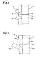
- Fig. 3 shows a state of the connection structure of the run-flat support body in the present invention seen from the axis side.
- the butted position of the elastic ring 5 and the butted position of the annular shell 4 are matched with each other, and the both butted ends 51a, 51b of the elastic ring 5 are made a non-joined state to the annular shell 4, respectively.
- the butted ends 51a, 51b of the elastic ring 5 are configured capable of deformation in the axial direction of the run-flat support body 3, respectively.
- Fig. 4 shows a state of another connection structure of the run-flat support body in the present invention seen from the axis side.
- the butted position of the elastic ring 5 and the butted position of the annular shell 4 are offset from each other, one butted end 51a of the elastic ring 5 covering the butted position of the annular shell 4 is in a non-joined state with respect to the annular shell 4, and the other butted end 51b of the elastic ring 5 is in a joined state with respect to the annular shell 4.
- the butted end 51a of the elastic ring 5 is constituted capable of deformation in the axial direction of the run-flat support body 3.
- Fig. 5 shows a state of another connection structure of the run-flat support body in the present invention seen from the axis side.
- the connection structure of Fig. 5 is different from the connection structure of Fig. 4 in a point that a tapered shape such that the one butted end 51a of the elastic ring 5 is overlapped with the other butted end 51b of the elastic ring 5 from the outside in the axial direction of the run-flat support body 3 is given to an interface between the butted ends 51a, 51b of the elastic ring 5.
- Fig. 6 shows a state of another connection structure of the run-flat support body in the present invention seen from the axis side.
- the connection structure of Fig. 6 is different from the connection structure of Fig. 4 in a point that a stepped shape such that the one butted end 51a of the elastic ring 5 is overlapped with the other butted end 51b of the elastic ring 5 from outside in the axial direction of the run-flat support body 3 is given to the interface between the butted ends 51a, 51b of the elastic ring 5.
- the butted end 51a of the elastic ring 5 in the non-joined state can be easily deformed outward in the axial direction of the run-flat support body 3 at the welding.
- the butted end 51b of the elastic ring 5 exerts a force opposing against a force that a bead portion of the rimmed pneumatic tire 2 is to move inward in the axial direction of the run-flat support body 3, stability of the elastic ring during run-flat running can be improved.
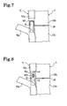
- Fig. 7 shows a state of another connection structure of the run-flat support body in the present invention seen from the axis side.
- the connection structure of Fig. 7 is different from the connection structure of Fig. 4 in a point that a plate-shaped joining aid member 6 overlapped with the other butted end 41b of the annular shell 4 is provided at a portion covered by the elastic ring 5 at the one butted end 41a of the annular shell 4.
- This joining aid member 6 is joined to the inner circumferential face of the butted end 41a of the annular shell 4 in advance.
- the butted end 41b of the annular shell 4 and the joining aid member 6 are welded. That is, at the portion covered by the elastic ring 5, a welded portion W1 (shaded portion) is formed around the joining aid member 6.
- connection structure shown in Fig. 7 by overlapping the joining aid member 6 on the butted end 41b of the annular shell 4 at the welding, the butted ends 41a, 41b of the annular shell 4 become hard to be offset, which facilitates the welding work of the annular shell 4.
- Fig. 8 shows a state of another connection structure of the run-flat support body in the present invention seen from the axis side.
- the connection structure of Fig. 8 is different from the connection structure of Fig. 7 in a point that a through hole 6a is provided at a portion overlapping the other butted end 41b of the annular shell 4 in the joining aid member 6.
- Fig. 9 is a sectional view on arrow X-X of Fig. 8 and as shown in Fig. 9 , the butted end 41b of the annular shell 4 and the joining aid member 6 are welded along the inner edge portion of the through hole 6a. That is, at the portion covered by the elastic ring 5, a welded portion W2 (shaded portion) is formed along the inner edge portion of the through hole 6a of the joining aid member 6.
- connection structure shown in Figs. 8 and 9 since the welded portion W2 is formed only at a limited range, an influence of heat to the periphery can be minimized. If the welded portion is diffused more than necessary and gives a bad influence to the physical characteristics of the annular shell 4 and the elastic ring 5, the run-flat durability might be lowered.
- Fig. 10 shows a state of another connection structure of the run-flat support body in the present invention seen from the axis side.
- the connection structure of Fig. 10 is different from the connection structure of Fig. 8 in a point that a projection 7 to be inserted into the though hole 6a is provided at the portion corresponding to the through hole 6a of the joining aid member 6 in the other butted end 41b of the annular shell 4.
- Fig. 11 is a sectional view on arrow Y-Y in Fig. 10 and as shown in Fig. 11 , the projection 7 of the butted end 41b of the annular shell 4 and the joining aid member 6 are welded along the inner edge portion of the through hole 6a. That is, at the portion covered by the elastic ring 5, a welded portion W3 (shaded portion) is formed along the inner edge portion of the through hole 6a of the joining aid member 6.
- connection structure shown in Figs. 10 and 11 since the welded portion W3 is formed at a limited range, the influence of heat to the periphery can be minimized. Moreover, by inserting the projection 7 into the through hole 6a of the joining aid member 6, positioning at the welding is facilitated.
- each of the above-mentioned connection structures after the annular shell 4 is welded, the portion of the elastic ring 5 not joined to the annular shell is preferably attached to the annular shell 4 as necessary, but if the non-joined portion is sufficiently short, it can be left as it is. Also, each of the above-mentioned connection structures needs to be arranged at least at a single spot on the circumference of the run-flat support body, but it may be arranged at two or more spots.
Landscapes
- Engineering & Computer Science (AREA)
- Mechanical Engineering (AREA)
- Tires In General (AREA)
Applications Claiming Priority (2)
| Application Number | Priority Date | Filing Date | Title |
|---|---|---|---|
| JP2006133507A JP2007302136A (ja) | 2006-05-12 | 2006-05-12 | ランフラット用支持体及びその組み付け方法 |
| PCT/JP2007/059729 WO2007132762A1 (ja) | 2006-05-12 | 2007-05-11 | ランフラット用支持体及びその組み付け方法 |
Publications (2)
| Publication Number | Publication Date |
|---|---|
| EP2018979A1 true EP2018979A1 (de) | 2009-01-28 |
| EP2018979A4 EP2018979A4 (de) | 2010-06-09 |
Family
ID=38693856
Family Applications (1)
| Application Number | Title | Priority Date | Filing Date |
|---|---|---|---|
| EP07743164A Withdrawn EP2018979A4 (de) | 2006-05-12 | 2007-05-11 | Run-flat-stützkörper und montageverfahren dafür |
Country Status (4)
| Country | Link |
|---|---|
| US (1) | US20090277555A1 (de) |
| EP (1) | EP2018979A4 (de) |
| JP (1) | JP2007302136A (de) |
| WO (1) | WO2007132762A1 (de) |
Families Citing this family (1)
| Publication number | Priority date | Publication date | Assignee | Title |
|---|---|---|---|---|
| JP2009220695A (ja) * | 2008-03-17 | 2009-10-01 | Washimaiyaa Kk | タイヤ・ホイール組立体及びそのリム組み方法。 |
Family Cites Families (13)
| Publication number | Priority date | Publication date | Assignee | Title |
|---|---|---|---|---|
| DE2538948A1 (de) * | 1975-09-02 | 1977-03-03 | Continental Gummi Werke Ag | Luftbereiftes fahrzeugrad |
| US4293016A (en) * | 1980-03-24 | 1981-10-06 | The General Tire & Rubber Co. | Pneumatic tire assembly |
| US4674549A (en) * | 1985-09-03 | 1987-06-23 | The Budd Company | Bead lock device |
| US5435363A (en) * | 1993-02-19 | 1995-07-25 | Pender; David R. | Run-flat pneumatic tires including plural separate inserts |
| DE19707090A1 (de) | 1997-02-24 | 1998-08-27 | Continental Ag | Luftbereiftes Fahrzeugrad |
| DE19745409C2 (de) * | 1997-10-15 | 2002-06-20 | Continental Ag | Fahrzeugrad mit einem Notlaufstützkörper |
| DE10130291C2 (de) | 2001-06-26 | 2003-10-23 | Continental Ag | Notlaufstützkörper |
| DE10149086C5 (de) * | 2001-10-05 | 2006-05-04 | Ise Innomotive Systems Europe Gmbh | Verfahren zum Herstellen eines Notlauf-Stützkörpers für Notlauf-Fahrzeugräder |
| JP2004058866A (ja) | 2002-07-30 | 2004-02-26 | Bridgestone Corp | 支持体および空気入りランフラットタイヤ |
| JP2004181987A (ja) | 2002-11-29 | 2004-07-02 | Bridgestone Corp | 支持体及び空気入りランフラットタイヤ |
| KR20050102665A (ko) * | 2003-02-21 | 2005-10-26 | 요코하마 고무 가부시키가이샤 | 타이어/휠 조립체 및 런 플랫용 지지체 |
| DE102004013517A1 (de) * | 2004-03-19 | 2005-10-06 | Continental Aktiengesellschaft | Fahrzeugrad mit einem Notlaufstützkörper |
| JP2007030747A (ja) * | 2005-07-28 | 2007-02-08 | Yokohama Rubber Co Ltd:The | ランフラット用支持体、ランフラット用支持体付き空気入りタイヤ及びその作製方法 |
-
2006
- 2006-05-12 JP JP2006133507A patent/JP2007302136A/ja active Pending
-
2007
- 2007-05-11 EP EP07743164A patent/EP2018979A4/de not_active Withdrawn
- 2007-05-11 WO PCT/JP2007/059729 patent/WO2007132762A1/ja not_active Ceased
- 2007-05-11 US US12/297,117 patent/US20090277555A1/en not_active Abandoned
Also Published As
| Publication number | Publication date |
|---|---|
| US20090277555A1 (en) | 2009-11-12 |
| EP2018979A4 (de) | 2010-06-09 |
| WO2007132762A1 (ja) | 2007-11-22 |
| JP2007302136A (ja) | 2007-11-22 |
Similar Documents
| Publication | Publication Date | Title |
|---|---|---|
| JP2007302239A (ja) | 固定ストリップに取り付けられたフォーム支持リングを有するランフラットシステム | |
| JP4039909B2 (ja) | タイヤホイール組立体及びランフラット用支持体 | |
| EP2018979A1 (de) | Run-flat-stützkörper und montageverfahren dafür | |
| JP3980435B2 (ja) | タイヤホイール組立体及びランフラット用支持体 | |
| US6843286B1 (en) | Tire/wheel assembly, run-flat support member and manufacturing method therefor | |
| US20040035512A1 (en) | Tire/wheel assembly and pneumatic tire | |
| JP4039907B2 (ja) | ランフラットタイヤ及びタイヤホイール組立体 | |
| US7036543B2 (en) | Tire/wheel assembly | |
| JP4187094B2 (ja) | 緊急走行支持体を備えた自動車車輪及び緊急走行支持体 | |
| EP1908611A1 (de) | Run-flat-stützkörper, luftreifen mit run-flat-stützkörper und verfahren zur herstellung des reifens | |
| JP2004224331A (ja) | 支持体および空気入りランフラットタイヤ | |
| JP4384098B2 (ja) | ランフラット支持体と空気入りタイヤとの固定具 | |
| JP4461984B2 (ja) | タイヤホイール組立体及びランフラット用支持体 | |
| JP4145099B2 (ja) | タイヤホイール組立体及びランフラット用支持体 | |
| WO2021123901A1 (en) | Non-pneumatic wheel | |
| US7188648B2 (en) | Tire/wheel assembly and run-flat support member | |
| JP4371635B2 (ja) | タイヤホイール組立体及びランフラット用支持体 | |
| JP4222818B2 (ja) | タイヤホイール組立体 | |
| JP3952183B2 (ja) | タイヤホイール組立体及びランフラット用支持体 | |
| JP2004058866A (ja) | 支持体および空気入りランフラットタイヤ | |
| JP2005145142A (ja) | タイヤ/リム組立体用のランフラット支持体 | |
| JP2007131216A (ja) | ランフラットタイヤ用中子、ランフラットタイヤ及びランフラットタイヤのリム組み方法 | |
| JP2005335574A (ja) | 支持体および空気入りランフラットタイヤ | |
| JP2005138651A (ja) | 支持体および空気入りランフラットタイヤ | |
| JP2008307990A (ja) | 支持体および空気入りランフラットタイヤ |
Legal Events
| Date | Code | Title | Description |
|---|---|---|---|
| PUAI | Public reference made under article 153(3) epc to a published international application that has entered the european phase |
Free format text: ORIGINAL CODE: 0009012 |
|
| 17P | Request for examination filed |
Effective date: 20081104 |
|
| AK | Designated contracting states |
Kind code of ref document: A1 Designated state(s): AT BE BG CH CY CZ DE DK EE ES FI FR GB GR HU IE IS IT LI LT LU LV MC MT NL PL PT RO SE SI SK TR |
|
| AX | Request for extension of the european patent |
Extension state: AL BA HR MK RS |
|
| DAX | Request for extension of the european patent (deleted) | ||
| RBV | Designated contracting states (corrected) |
Designated state(s): DE FR |
|
| A4 | Supplementary search report drawn up and despatched |
Effective date: 20100512 |
|
| STAA | Information on the status of an ep patent application or granted ep patent |
Free format text: STATUS: THE APPLICATION HAS BEEN WITHDRAWN |
|
| 18W | Application withdrawn |
Effective date: 20100929 |