EP2018918A1 - Ceramic drill for high-speed perforation of composite materials - Google Patents
Ceramic drill for high-speed perforation of composite materials Download PDFInfo
- Publication number
- EP2018918A1 EP2018918A1 EP08160909A EP08160909A EP2018918A1 EP 2018918 A1 EP2018918 A1 EP 2018918A1 EP 08160909 A EP08160909 A EP 08160909A EP 08160909 A EP08160909 A EP 08160909A EP 2018918 A1 EP2018918 A1 EP 2018918A1
- Authority
- EP
- European Patent Office
- Prior art keywords
- drill
- ceramic
- angle
- plane
- axis
- Prior art date
- Legal status (The legal status is an assumption and is not a legal conclusion. Google has not performed a legal analysis and makes no representation as to the accuracy of the status listed.)
- Granted
Links
- 239000000919 ceramic Substances 0.000 title claims abstract description 30
- 239000002131 composite material Substances 0.000 title claims abstract description 30
- 238000005553 drilling Methods 0.000 claims abstract description 39
- 238000000034 method Methods 0.000 claims abstract description 9
- 238000005520 cutting process Methods 0.000 claims description 68
- 239000000463 material Substances 0.000 claims description 27
- 239000003822 epoxy resin Substances 0.000 claims description 9
- 229920000647 polyepoxide Polymers 0.000 claims description 9
- 229920000049 Carbon (fiber) Polymers 0.000 claims description 8
- 239000004917 carbon fiber Substances 0.000 claims description 8
- 239000011159 matrix material Substances 0.000 claims description 8
- VNWKTOKETHGBQD-UHFFFAOYSA-N methane Chemical compound C VNWKTOKETHGBQD-UHFFFAOYSA-N 0.000 claims description 7
- 229910010293 ceramic material Inorganic materials 0.000 claims description 6
- 230000002093 peripheral effect Effects 0.000 claims description 5
- 238000003754 machining Methods 0.000 description 10
- 230000032798 delamination Effects 0.000 description 7
- UONOETXJSWQNOL-UHFFFAOYSA-N tungsten carbide Chemical compound [W+]#[C-] UONOETXJSWQNOL-UHFFFAOYSA-N 0.000 description 5
- ZYHIULSBMGTPBF-UHFFFAOYSA-N 1-(3-aminopropyl)-3-(2,6-dimethylphenyl)urea Chemical compound Cc1cccc(C)c1NC(=O)NCCCN ZYHIULSBMGTPBF-UHFFFAOYSA-N 0.000 description 4
- 238000004519 manufacturing process Methods 0.000 description 4
- 239000007769 metal material Substances 0.000 description 3
- 229910052581 Si3N4 Inorganic materials 0.000 description 2
- MCMNRKCIXSYSNV-UHFFFAOYSA-N Zirconium dioxide Chemical compound O=[Zr]=O MCMNRKCIXSYSNV-UHFFFAOYSA-N 0.000 description 2
- 230000015556 catabolic process Effects 0.000 description 2
- 230000000295 complement effect Effects 0.000 description 2
- 238000006731 degradation reaction Methods 0.000 description 2
- 229910003460 diamond Inorganic materials 0.000 description 2
- 239000010432 diamond Substances 0.000 description 2
- 229910052751 metal Inorganic materials 0.000 description 2
- 239000002184 metal Substances 0.000 description 2
- 238000003801 milling Methods 0.000 description 2
- HQVNEWCFYHHQES-UHFFFAOYSA-N silicon nitride Chemical compound N12[Si]34N5[Si]62N3[Si]51N64 HQVNEWCFYHHQES-UHFFFAOYSA-N 0.000 description 2
- 229910000601 superalloy Inorganic materials 0.000 description 2
- 230000008646 thermal stress Effects 0.000 description 2
- 229910018072 Al 2 O 3 Inorganic materials 0.000 description 1
- 241001475178 Dira Species 0.000 description 1
- 229920000297 Rayon Polymers 0.000 description 1
- 229910000831 Steel Inorganic materials 0.000 description 1
- QCWXUUIWCKQGHC-UHFFFAOYSA-N Zirconium Chemical compound [Zr] QCWXUUIWCKQGHC-UHFFFAOYSA-N 0.000 description 1
- 238000005299 abrasion Methods 0.000 description 1
- 230000006978 adaptation Effects 0.000 description 1
- PNEYBMLMFCGWSK-UHFFFAOYSA-N aluminium oxide Inorganic materials [O-2].[O-2].[O-2].[Al+3].[Al+3] PNEYBMLMFCGWSK-UHFFFAOYSA-N 0.000 description 1
- 238000005452 bending Methods 0.000 description 1
- 238000005219 brazing Methods 0.000 description 1
- 239000000470 constituent Substances 0.000 description 1
- 239000000835 fiber Substances 0.000 description 1
- 230000017525 heat dissipation Effects 0.000 description 1
- 239000000314 lubricant Substances 0.000 description 1
- 230000002028 premature Effects 0.000 description 1
- 239000002964 rayon Substances 0.000 description 1
- 239000012858 resilient material Substances 0.000 description 1
- HBMJWWWQQXIZIP-UHFFFAOYSA-N silicon carbide Chemical compound [Si+]#[C-] HBMJWWWQQXIZIP-UHFFFAOYSA-N 0.000 description 1
- LXMSZDCAJNLERA-ZHYRCANASA-N spironolactone Chemical compound C([C@@H]1[C@]2(C)CC[C@@H]3[C@@]4(C)CCC(=O)C=C4C[C@H]([C@@H]13)SC(=O)C)C[C@@]21CCC(=O)O1 LXMSZDCAJNLERA-ZHYRCANASA-N 0.000 description 1
- 239000010959 steel Substances 0.000 description 1
- 230000035882 stress Effects 0.000 description 1
- 229910052726 zirconium Inorganic materials 0.000 description 1
Images


Classifications
-
- B—PERFORMING OPERATIONS; TRANSPORTING
- B23—MACHINE TOOLS; METAL-WORKING NOT OTHERWISE PROVIDED FOR
- B23B—TURNING; BORING
- B23B51/00—Tools for drilling machines
- B23B51/0081—Conical drills
-
- B—PERFORMING OPERATIONS; TRANSPORTING
- B23—MACHINE TOOLS; METAL-WORKING NOT OTHERWISE PROVIDED FOR
- B23B—TURNING; BORING
- B23B51/00—Tools for drilling machines
- B23B51/02—Twist drills
-
- B—PERFORMING OPERATIONS; TRANSPORTING
- B23—MACHINE TOOLS; METAL-WORKING NOT OTHERWISE PROVIDED FOR
- B23B—TURNING; BORING
- B23B2215/00—Details of workpieces
- B23B2215/04—Aircraft components
-
- B—PERFORMING OPERATIONS; TRANSPORTING
- B23—MACHINE TOOLS; METAL-WORKING NOT OTHERWISE PROVIDED FOR
- B23B—TURNING; BORING
- B23B2226/00—Materials of tools or workpieces not comprising a metal
- B23B2226/18—Ceramic
-
- B—PERFORMING OPERATIONS; TRANSPORTING
- B23—MACHINE TOOLS; METAL-WORKING NOT OTHERWISE PROVIDED FOR
- B23B—TURNING; BORING
- B23B2226/00—Materials of tools or workpieces not comprising a metal
- B23B2226/27—Composites
-
- B—PERFORMING OPERATIONS; TRANSPORTING
- B23—MACHINE TOOLS; METAL-WORKING NOT OTHERWISE PROVIDED FOR
- B23B—TURNING; BORING
- B23B2226/00—Materials of tools or workpieces not comprising a metal
- B23B2226/27—Composites
- B23B2226/275—Carbon fibre reinforced carbon composites
-
- B—PERFORMING OPERATIONS; TRANSPORTING
- B23—MACHINE TOOLS; METAL-WORKING NOT OTHERWISE PROVIDED FOR
- B23B—TURNING; BORING
- B23B2226/00—Materials of tools or workpieces not comprising a metal
- B23B2226/36—Epoxy
-
- B—PERFORMING OPERATIONS; TRANSPORTING
- B23—MACHINE TOOLS; METAL-WORKING NOT OTHERWISE PROVIDED FOR
- B23B—TURNING; BORING
- B23B2251/00—Details of tools for drilling machines
- B23B2251/04—Angles, e.g. cutting angles
-
- B—PERFORMING OPERATIONS; TRANSPORTING
- B23—MACHINE TOOLS; METAL-WORKING NOT OTHERWISE PROVIDED FOR
- B23B—TURNING; BORING
- B23B2251/00—Details of tools for drilling machines
- B23B2251/14—Configuration of the cutting part, i.e. the main cutting edges
-
- B—PERFORMING OPERATIONS; TRANSPORTING
- B23—MACHINE TOOLS; METAL-WORKING NOT OTHERWISE PROVIDED FOR
- B23B—TURNING; BORING
- B23B2251/00—Details of tools for drilling machines
- B23B2251/18—Configuration of the drill point
-
- B—PERFORMING OPERATIONS; TRANSPORTING
- B23—MACHINE TOOLS; METAL-WORKING NOT OTHERWISE PROVIDED FOR
- B23B—TURNING; BORING
- B23B2270/00—Details of turning, boring or drilling machines, processes or tools not otherwise provided for
- B23B2270/54—Methods of turning, boring or drilling not otherwise provided for
-
- Y—GENERAL TAGGING OF NEW TECHNOLOGICAL DEVELOPMENTS; GENERAL TAGGING OF CROSS-SECTIONAL TECHNOLOGIES SPANNING OVER SEVERAL SECTIONS OF THE IPC; TECHNICAL SUBJECTS COVERED BY FORMER USPC CROSS-REFERENCE ART COLLECTIONS [XRACs] AND DIGESTS
- Y10—TECHNICAL SUBJECTS COVERED BY FORMER USPC
- Y10T—TECHNICAL SUBJECTS COVERED BY FORMER US CLASSIFICATION
- Y10T408/00—Cutting by use of rotating axially moving tool
- Y10T408/03—Processes
-
- Y—GENERAL TAGGING OF NEW TECHNOLOGICAL DEVELOPMENTS; GENERAL TAGGING OF CROSS-SECTIONAL TECHNOLOGIES SPANNING OVER SEVERAL SECTIONS OF THE IPC; TECHNICAL SUBJECTS COVERED BY FORMER USPC CROSS-REFERENCE ART COLLECTIONS [XRACs] AND DIGESTS
- Y10—TECHNICAL SUBJECTS COVERED BY FORMER USPC
- Y10T—TECHNICAL SUBJECTS COVERED BY FORMER US CLASSIFICATION
- Y10T408/00—Cutting by use of rotating axially moving tool
- Y10T408/78—Tool of specific diverse material
-
- Y—GENERAL TAGGING OF NEW TECHNOLOGICAL DEVELOPMENTS; GENERAL TAGGING OF CROSS-SECTIONAL TECHNOLOGIES SPANNING OVER SEVERAL SECTIONS OF THE IPC; TECHNICAL SUBJECTS COVERED BY FORMER USPC CROSS-REFERENCE ART COLLECTIONS [XRACs] AND DIGESTS
- Y10—TECHNICAL SUBJECTS COVERED BY FORMER USPC
- Y10T—TECHNICAL SUBJECTS COVERED BY FORMER US CLASSIFICATION
- Y10T408/00—Cutting by use of rotating axially moving tool
- Y10T408/89—Tool or Tool with support
- Y10T408/899—Having inversely angled cutting edge
-
- Y—GENERAL TAGGING OF NEW TECHNOLOGICAL DEVELOPMENTS; GENERAL TAGGING OF CROSS-SECTIONAL TECHNOLOGIES SPANNING OVER SEVERAL SECTIONS OF THE IPC; TECHNICAL SUBJECTS COVERED BY FORMER USPC CROSS-REFERENCE ART COLLECTIONS [XRACs] AND DIGESTS
- Y10—TECHNICAL SUBJECTS COVERED BY FORMER USPC
- Y10T—TECHNICAL SUBJECTS COVERED BY FORMER US CLASSIFICATION
- Y10T408/00—Cutting by use of rotating axially moving tool
- Y10T408/89—Tool or Tool with support
- Y10T408/909—Having peripherally spaced cutting edges
- Y10T408/9095—Having peripherally spaced cutting edges with axially extending relief channel
- Y10T408/9097—Spiral channel
Definitions
- the invention relates to a drill made of ceramic material. It finds a particular application for the drilling at very high speed of composite material parts, especially carbon fiber composite material whose matrix is an epoxy resin. This type of material, thanks to its high mechanical characteristics and low density, is widely used in fields such as aeronautics.
- Ceramics because of their high hardness and high resistance to high temperatures, are experiencing a development in the manufacture of cutting tools.
- Known ceramic cutting tools such as those described in the patent document EP 0 477 093 are generally milling or turning tools and allow to perform high speed machining on materials of great hardness.
- the constraints that can be applied on a drill bit are greater than those that can be applied to a cutter during a drilling operation. a milling operation. These constraints make it more difficult to use ceramic drills to perform very high-speed drilling in materials of high hardness such as metal superalloys.
- the patent FR 2 861 001 provides a solution to this problem by proposing a ceramic drill whose particular geometry is suitable for drilling at very high speed in metal materials of great hardness. This geometry makes it possible to overcome the problems related to the lower resistance to torsion of a ceramic drill compared to steel drills and reach peripheral cutting speeds greater than 400 meters / minute, while guaranteeing a long life. of satisfactory forest life.
- the torsional forces applied to the drills are increasingly important, firstly because the outer surface of the drill rubbing against the cylindrical inner surface of the borehole increases. , but also because, for high drilling speeds, the drill must be able to efficiently remove a large amount of chips, which can cause stuffing in the drill, increasing the torsional forces applied to the drill bit and the risks of breaking it.
- the cutting edge of the drill must be able to withstand a large cutting speed gradient, since in its center the cutting speed is zero and it increases gradually to reach a maximum on the periphery of the forest.
- Another constraint related to the machining, and in particular drilling, of composite materials is that the operation must be performed while maintaining the integrity of the pierced material.
- the conventional drills exert efforts on the internal cylindrical surface of the drilled holes globally directed from the drill to the material to be machined. This is causing delamination of the material, which is absolutely necessary to avoid.
- the drills known from the prior art are not suitable for machining composite materials at high speed and suitably, particularly carbon fiber composite materials whose matrix is an epoxy resin.
- the drill described in the patent FR 2 861 001 is well suited for high speed drilling of metal materials of great hardness, but is not suitable for composite materials, causing in this case a delamination of the material to be machined.
- the object of the invention is to avoid the above-mentioned drawbacks and to provide a technically simple and inexpensive solution, making it possible to improve the performance of ceramic drills and to pierce at very high speed composite materials such as composite materials.
- composite materials such as composite materials.
- the invention proposes a new type of drill capable of achieving a specific cutting energy of between 30 and 50 W / cm 3 / min, comprising an active part made of ceramic material and whose geometry is optimized and suitable for drilling with a large diameter. speed of composite materials.
- This new type of The drill is able to withstand the mechanical forces generated by the material machined at these speeds.
- the subject of the invention is a drill comprising a shank, a portion cut in the form of a truncated cone extending up to the shank and whose base is located at a free axial end of the drill, said end having at least two main cutting edges interconnected by two central edges, said cut portion having two lips and two flutes extending helically alternately about a longitudinal axis of rotation of the drill, the lips and the flutes extending from the free axial end to the drill shank, each lip having a ridge and flute having a main cutting face adjacent to a ridge and a main ridge, which ridge intersects with a face of main draft at the free axial end of the drill, the main flanks each extending, on the side of the lips, by a face of against-d puille, two punctures extending from the central edges to the periphery of the drill and forming two secondary cutting faces, at least one end portion of the cut portion of the drill being made of ceramic material, said drill being remarkable in that each
- flanks and undercuts of the drill head are extended, radially outward, by, respectively, a first curved chamfer forming a flank surface and a second chamfer forming an undercut surface. . Inward bending of the first and second chamfers avoids delamination of the composite material drilled by the drill bit.
- the invention also relates to a method of drilling composite materials using a ceramic drill bit of the type described above, wherein the drill has a peripheral cutting speed of between 600 and 1000 m / min.
- the drill has an advance of between 0.05 and 0.20 mm / revolution.
- the drilling can be carried out dry, without prior centering operation. A single drilling operation may be sufficient to achieve the final hole.
- the depth of the drilling may be greater than the diameter of the cut portion of the drill bit.
- the material to be pierced is a carbon fiber composite material whose matrix is an epoxy resin.
- the Figures 1 to 5 represent by way of example a ceramic monoblock drill for high-speed drilling of composite materials, in particular composite carbon fiber materials whose matrix is an epoxy resin.
- This ceramic drill bit 1 (see figure 1 ) a cylindrical tail 2 or conical and a cut portion 3 extending from the tail in the axis 4 of the drill to a free axial end 13b.
- the shank may be smooth as illustrated herein or have an annular groove (not shown) for clamping the drill into the chuck of a machine tool (not shown).
- the free axial end 6 of the tail ends with a chamfer 7 to facilitate its introduction into the mandrel of the machine tool.
- the tail 2 and the cut portion 3 of the drill bit 1 can be connected to each other by a chamfer 5, necessary when the outer diameters of the tail and the cut portion are different.
- the cut portion 3 of the drill 1 comprises two lips 8 and two flutes 9, extending alternately about the axis 4 from the shank 2 to the free axial end 13b of the drill 1.
- the lips 8 and the flutes 9 are wound helically about the axis 4 with a helix angle 11 of between 25 and 40 degrees.
- Each lip 8 comprises a strip 12, intended to slide against the inner wall of a hole to be drilled, and a release surface 13.
- the strips 12 and the clearance surfaces 13 are helically shaped.
- each strip has a thickness 14 which is less than or equal to one tenth of the diameter d of the cut portion 3 of the drill.
- Each flute 9 has a main cutting face 16, adjacent to a strip 12. The intersection of the strip 12 and the main cutting face 16 forms an edge called leading edge 17 of the strip 12.
- each strip 12 extends radially from the outside of the drill 1 towards its axis 4 by a curved chamfer 25, followed by a main clearance face 21.
- intersection between each main draft face 21 and the corresponding flute 9 forms a main cutting edge 18.
- the two main cutting edges 18 extend at the central portion of the drill, by two central ridges 19.
- the flanks main 21 extend, on the side of the lips 8, by an undercut face 30.
- the undercuts faces 30 also have a chamfer 31 disposed in the extension of the curved chamfers 25.
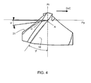
- the cutting direction and the direction of advance of the drill are respectively marked DirC and DirA.
- the geometry of the drill according to the invention is such that the orthogonal plane Po of the drill is merged with the normal plane Pn at the main cutting edge 18.
- each edge plane Ps forms with the work plane Pf an angle ⁇ r, called the direction angle of the main cutting edge 18, between 55 and 65 degrees. Furthermore, each edge plane Ps forms with the rearward plane Pp corresponding to an angle ⁇ r, called complementary steering angle of the drill 1, of between 27 and 37 degrees. The two central edges 19 form between them an angle ⁇ c between 142 and 162 degrees.
- the edge formed by the intersection between a curved chamfer 25 and the corresponding flute 9 is inclined at an angle 25b with respect to the plane Pp, so that the point B corresponding to the radially external end this edge is farther away from the shank 3 of the drill than the point A.
- the angle 25b is between 3 and 9 degrees approximately.
- the distance 18a in the radial direction between the points A of each main cutting edge 18 is between the diameter d of the cut portion 3 minus 2 mm and the diameter d plus 2 mm.
- each main cutting edge 18 forms an angle ⁇ p with the reference plane Pr.
- the angle ⁇ p is called the cutting angle towards the rear of the drill 1 and is between approximately 13 and 23 degrees.
- the flanks 21 have a width 21b of between 1 and 4 mm.
- Each central edge 19 forms with the reference plane Pr an angle ⁇ c between 32 and 42 degrees approximately.
- the intersection between each curved chamfer 25 and the chamfer 31 made on the corresponding undercut face 30 forms a line segment whose ends are marked C and D, C being the end furthest from the axis 4 of the forest.
- the line segment AB of a curved chamfer 25, B corresponding to the fourth vertex of the curved chamfer forms with the reference plane Pr an angle ⁇ i of between approximately 2 and 4 degrees.
- the line segment AD forms with the reference plane Pr an angle ⁇ j between 69 and 79 degrees approximately.
- the intersection between each undercut face 30 and the corresponding chamfer 31 forms with the reference plane Pr an angle ⁇ k between about 50 and 60 degrees.
- the straight line passing through the axis 4 of the drill and by the intersection between a flute 9 and the corresponding clearance surface 13 forms, with the plane Pr, an angle ⁇ g of between approximately 60 and 90 degrees. .
- each main cutting face 16 forms with the reference plane Pr an angle ⁇ f, called the lateral cutting angle of the drill bit 1
- a positive angle or Negative cutting is determined by the orientation of the main cutting face 16 with respect to the cutting direction DirC: when the cutting face is inclined from the cutting edge to the cutting direction DirC, the cutting angle is said to be negative, and conversely, when the cutting face 16 is inclined from the cutting edge in the opposite direction to the cutting direction DirC, the cutting angle ⁇ f is positive.
- the cutting angle ⁇ f of the drill 1 is positive.
- each curved chamfer 25 forms with the rearward plane Pp of the drill 1 an angle ⁇ e of between about 6 and 10 degrees.
- the cut portion 3 of the drill has a generally outer truncated cone shape.
- the base of the truncated cone is located at the free axial end 13b of the drill and the conical angle 26 of the cut portion 3 can be up to about 3 degrees.
- Two secondary cutting faces 28, formed by making two pits 27 extend from the central edges 19 towards the periphery of the drill 1.
- the pits 27 are delimited by two straight line segments: a first line segment 27a starting from the intersection between a main cutting edge 18 and the edge corresponding central 19 and a second line segment forming the intersection between the puncture 27 and the adjacent undercut face 30.
- the segments 27a and 27b are interconnected by a curvilinear portion 27c.
- the segment 27b forms an angle 27d relative to the axis 4 of the drill between 1 and about 15 degrees.
- the segments 27a and 27b form between them an angle 27e of between 25 and 35 degrees approximately.
- each lug 12 is rounded with a radius of at least 2 microns and up to 5 microns. Preferably, this radius will be of the order of about 2 micrometers.
- the geometry of the drill according to the invention makes it possible to reduce the forces directly related to cutting while avoiding delamination. It also reduces the forces resulting from the friction between the listels 12 of the drill and the inner wall of the hole to be drilled.
- the drill according to the invention allows very high speed drilling of composite materials because it withstands the high forces produced in these drilling conditions, while avoiding the delamination of the pierced material. With this drill, it can be further considered to drill depths greater than the diameter of the tool without it wears prematurely. The delamination of the composite material is avoided thanks to the presence of the curved chamfers 25.
- the radially outer ends of the chamfers 25 machining the composite material before their radially inner ends, the forces applied by the curved chamfers on the material to be machined are globally directed towards the axis 4 of the drill.
- the material is trapped in the drill, is not pushed outwardly and therefore the various constituent layers of the composite material do not undergo any effort to separate them from each other.
- the delamination of the material is then avoided.
- the range defined for the helix angle 11 makes it possible to accommodate on the periphery of the drill 1 flutes 9 which are large enough to evacuate the large amount of chips produced during high speed machining, without reducing the resistance of the drill to the torsion.
- the drill can be monobloc, that is to say that the tail 2 and the cut portion 3 are made of the same ceramic material and in one piece.
- the drill can also consist of two parts made of different materials, one for the tail and the other for the part active, ie the cut part.
- the cut portion of the drill bit may also be composed of two different materials: the portion near the free axial end of the drill is then ceramic material, while the remaining portion may be in the same material as the tail.
- the material constituting the active part of the cut part is preferably a ceramic based on alumina oxide reinforced with silicon carbide (SiC) fibers, or based on zirconia, silicon nitride (called SiAION) or is a so-called "mixed" ceramic reinforced or not, a mixed ceramic being composed of zirconium and silicon nitride.
- SiC silicon carbide
- SiAION silicon nitride
- these two parts may be bonded together for example by brazing.
- the cut portion is then ceramic while the tail is made of a resilient material greater than that of the ceramic to better withstand the forces applied to the drill 1.
- the material of the drill shank may for example be a tungsten carbide .
- the ceramic drill bit 1 according to the invention is particularly well suited to piercing composite materials such as composite carbon fiber materials whose matrix is an epoxy resin. Its use does not require any particular adaptation, especially of the machine tool, compared to the use of a drill whose active part is tungsten carbide. It is only necessary that the machine tool allows tool rotation speeds that are sufficiently high and suitable for high speed machining.
- the range of use of the drill in terms of cutting speed and feed rate can be determined by an approach of the type Cut Material Tool (COM).
- COM Cut Material Tool
- the drill according to the invention makes it possible to achieve, depending on the diameter of the drill, a peripheral cutting speed of between 600 and 1000 m / min, for an advance of between 0.05 and 0.20 mm.
- the drill according to the invention makes it possible to reduce considerably the constraints exerted on the latter, whether mechanical (torsional and compressive forces) or thermal.
- the thermal stresses are reduced by ensuring heat dissipation via the chips that quickly convey this energy outside the piercing.
- the use of the drill outside the recommended cutting speed and advance speed ranges is possible but leads to accelerated degradation of the tool and thus a decrease in its life.
- the drill according to the invention makes it possible, for drilling composite materials, to divide the drilling time by ten. The impact of the geometry of the drill on its life is significant since the number of holes drilled by the same tool before it is necessary to change is multiplied by five.
- the drilling is carried out dry without the use of lubricant and constitutes a roughing operation that does not require a prior pointing operation for centering the drill bit.
Abstract
Description
L'invention concerne un foret en matière céramique. Elle trouve une application particulière pour le perçage à très grande vitesse de pièces en matériau composite, notamment en matériau composite à fibres de carbone dont la matrice est une résine d'époxy. Ce type de matériau, grâce à ses caractéristiques mécaniques élevées et à sa faible masse volumique, est largement utilisé dans des domaines tels que l'aéronautique.The invention relates to a drill made of ceramic material. It finds a particular application for the drilling at very high speed of composite material parts, especially carbon fiber composite material whose matrix is an epoxy resin. This type of material, thanks to its high mechanical characteristics and low density, is widely used in fields such as aeronautics.
Aujourd'hui, les céramiques, du fait de leur dureté importante et de leur grande résistance aux températures élevées, connaissent un développement dans la fabrication des outils de coupe. Les outils de coupe en céramique connus, tels que ceux décrits dans le document de brevet
Le brevet
La tendance actuelle, notamment en aéronautique, est au développement de l'emploi de matériaux composites, ce type de matériau étant très intéressant car ayant de bonnes caractéristiques mécaniques, tout en ayant une masse volumique plus faible que les matériaux métalliques.The current trend, particularly in aeronautics, is the development of the use of composite materials, this type of material being very interesting because having good mechanical characteristics, while having a lower density than metal materials.
Le perçage des matériaux composites, et notamment des matériaux composites à fibres de carbone dont la matrice est une résine d'époxy, est à l'heure actuelle réalisé à l'aide de forets monoblocs en carbure de tungstène ou de foret munis d'inserts en diamant polycristallin (ou PCD : polycristal diamond) sur l'arête de coupe. L'utilisation de ces outils permet d'atteindre des vitesses de coupe périphérique comprises entre 20 et 80 mètres/minute par exemple pour les outils en carbure de tungstène. Au-delà de cette plage de vitesses, l'usure de la partie active de l'outil, constituée de carbure de tungstène ou de PCD, est fortement accélérée. En effet, les efforts de coupe, exercés par ces forets sur les pièces à percer, et les frottements entre les surfaces radialement externes des forets et les surfaces cylindriques internes des trous percés, induisent des contraintes thermiques dans les forets et dans les pièces à percer ainsi qu'un phénomène d'abrasion qui provoquent une dégradation accélérée des forets et une déformation des pièces.The drilling of composite materials, and in particular of carbon fiber composite materials whose matrix is an epoxy resin, is currently carried out using one-piece tungsten carbide or drill bits with inserts. polycrystalline diamond (or PCD: polycrystal diamond) on the cutting edge. The use of these tools makes it possible to achieve peripheral cutting speeds of between 20 and 80 meters / minute, for example for tungsten carbide tools. Beyond this range of speeds, the wear of the active part of the tool, made of tungsten carbide or PCD, is greatly accelerated. In fact, the cutting forces exerted by these drills on the parts to be drilled, and the friction between the radially outer surfaces of the drills and the internal cylindrical surfaces of the drilled holes, induce thermal stresses in the drills and in the parts to be drilled. as well as an abrasion phenomenon which causes accelerated degradation of the drills and deformation of the parts.
En outre, au fur et à mesure que la profondeur des perçages augmente, les efforts de torsion appliqués sur les forets sont de plus en plus importants, d'une part parce que la surface externe du foret frottant contre la surface cylindrique interne du perçage augmente, mais également parce que, pour des grandes vitesses de perçage, le foret doit être capable d'évacuer efficacement une grande quantité de copeaux, ce qui peut provoquer des phénomènes de bourrage dans le foret, augmentant ainsi les efforts de torsion appliqués sur le foret et les risques de cassure de celui-ci.In addition, as the depth of the holes increases, the torsional forces applied to the drills are increasingly important, firstly because the outer surface of the drill rubbing against the cylindrical inner surface of the borehole increases. , but also because, for high drilling speeds, the drill must be able to efficiently remove a large amount of chips, which can cause stuffing in the drill, increasing the torsional forces applied to the drill bit and the risks of breaking it.
Par ailleurs, dans le cas d'un perçage, l'arête coupante du foret doit être capable de supporter un gradient de vitesse de coupe important, puisqu'en son centre la vitesse de coupe est nulle et qu'elle augmente progressivement pour atteindre un maximum à la périphérie du foret.Furthermore, in the case of a drilling, the cutting edge of the drill must be able to withstand a large cutting speed gradient, since in its center the cutting speed is zero and it increases gradually to reach a maximum on the periphery of the forest.
Cette contrainte supplémentaire contribue à l'usure prématurée et à l'augmentation du risque de cassure de l'outil.This additional stress contributes to premature wear and increases the risk of breakage of the tool.
Une autre contrainte liée à l'usinage, et en particulier au perçage, de matériaux composites est que l'opération doit être réalisée tout en conservant l'intégrité du matériau percé. Lors d'une opération de perçage, les forets conventionnels exercent des efforts sur la surface cylindrique interne des trous percés globalement dirigés du foret vers le matériau à usiner. Ceci est à l'origine d'un délaminage du matériau, qu'il est absolument nécessaire d'éviter.Another constraint related to the machining, and in particular drilling, of composite materials is that the operation must be performed while maintaining the integrity of the pierced material. During a drilling operation, the conventional drills exert efforts on the internal cylindrical surface of the drilled holes globally directed from the drill to the material to be machined. This is causing delamination of the material, which is absolutely necessary to avoid.
Ainsi, bien qu'il existe sur le marché des outils, notamment des forets dont la partie active est en céramique, capables d'usiner à grande vitesse des matériaux de grande dureté tels que des superalliages métalliques, les forets connus de l'art antérieur ne permettent pas d'usiner à grande vitesse et de façon convenable les matériaux composites, en particulier les matériaux composites à fibres de carbone dont la matrice est une résine d'époxy. Par exemple, le foret décrit dans le brevet
Le but de l'invention est d'éviter les inconvénients précités et d'apporter une solution techniquement simple et peu coûteuse, permettant d'améliorer les performances des forets céramiques et de percer à très grande vitesse des matériaux composites tels que les matériaux composites à fibres de carbone dont la matrice est une résine d'époxy, sans délaminer le matériau, ni élever la température d'usinage au-delà de 200°C, température à partir de laquelle les caractéristiques mécaniques des matériaux composites chutent. Percer à très grande vitesse ce type de matériaux, sans les délaminer, permet d'augmenter la productivité en diminuant le temps d'usinage. Pour cela l'invention propose un nouveau type de foret capable d'atteindre une énergie spécifique de coupe comprise entre 30 et 50W/cm3/min, comportant une partie active en matériau céramique et dont la géométrie est optimisée et adaptée au perçage à grande vitesse des matériaux composite. Ce nouveau type de foret est capable de supporter les efforts mécaniques engendrés par la matériau usiné à ces vitesses.The object of the invention is to avoid the above-mentioned drawbacks and to provide a technically simple and inexpensive solution, making it possible to improve the performance of ceramic drills and to pierce at very high speed composite materials such as composite materials. carbon fibers whose matrix is an epoxy resin, without delaminating the material, nor raising the machining temperature beyond 200 ° C, temperature from which the mechanical characteristics of the composite materials fall. Drilling these types of materials at a very high speed, without delaminating them, makes it possible to increase productivity by reducing the machining time. For this purpose, the invention proposes a new type of drill capable of achieving a specific cutting energy of between 30 and 50 W / cm 3 / min, comprising an active part made of ceramic material and whose geometry is optimized and suitable for drilling with a large diameter. speed of composite materials. This new type of The drill is able to withstand the mechanical forces generated by the material machined at these speeds.
A cet effet, l'invention a pour objet un foret comportant une queue, une partie taillée en forme de tronc de cône s'étendant jusqu'à la queue et dont la base est située au niveau d'une extrémité axiale libre du foret, ladite extrémité comportant au moins deux arêtes de coupe principales reliées entre elles par deux arêtes centrales, ladite partie taillée comportant deux lèvres et deux goujures s'étendant de façon hélicoïdale en alternance autour d'un axe longitudinal de rotation du foret, les lèvres et les goujures s'étendant depuis l'extrémité axiale libre vers la queue du foret, chaque lèvre comportant un listel et chaque goujure comportant une face de coupe principale adjacente à un listel et à une arête de coupe principale, laquelle arête forme une intersection avec une face de dépouille principale au niveau de l'extrémité axiale libre du foret, les faces de dépouille principales se prolongeant chacune, du côté des lèvres, par une face de contre-dépouille, deux piqûres s'étendant depuis les arêtes centrales vers la périphérie du foret et formant deux faces de coupe secondaires, au moins une portion d'extrémité de la partie taillée du foret étant réalisée en matériau céramique, ledit foret étant remarquable en ce que chaque listel se prolonge radialement, vers l'axe de rotation du foret, par un chanfrein incurvé, suivi d'une face de dépouille principale, de sorte que l'intersection entre chaque chanfrein incurvé et la goujure adjacente est formée par une arête dont une extrémité radialement externe est plus éloignée axialement, selon l'axe de rotation du foret, de la queue du foret que ne l'est une extrémité radialement interne de ladite arête, et en ce que les chanfreins incurvés se prolongent chacun, du côté des faces de contre-dépouille, par un chanfrein.For this purpose, the subject of the invention is a drill comprising a shank, a portion cut in the form of a truncated cone extending up to the shank and whose base is located at a free axial end of the drill, said end having at least two main cutting edges interconnected by two central edges, said cut portion having two lips and two flutes extending helically alternately about a longitudinal axis of rotation of the drill, the lips and the flutes extending from the free axial end to the drill shank, each lip having a ridge and flute having a main cutting face adjacent to a ridge and a main ridge, which ridge intersects with a face of main draft at the free axial end of the drill, the main flanks each extending, on the side of the lips, by a face of against-d puille, two punctures extending from the central edges to the periphery of the drill and forming two secondary cutting faces, at least one end portion of the cut portion of the drill being made of ceramic material, said drill being remarkable in that each strip extends radially towards the axis of rotation of the drill bit by a curved chamfer, followed by a main relief face, so that the intersection between each curved chamfer and the adjacent flute is formed by a ridge of which one radially outer end is further axially, along the axis of rotation of the drill bit, the drill bit than is a radially inner end of said edge, and in that the curved chamfers are each extended, the side faces undercut, by a chamfer.
Ainsi, les faces de dépouille et de contre-dépouille de la tête du foret sont prolongées, radialement vers l'extérieur, par, respectivement, un premier chanfrein incurvé formant une surface de dépouille et par un second chanfrein formant une surface de contre-dépouille. L'incurvation vers l'intérieur des premier et second chanfreins permet d'éviter un délaminage du matériau composite percé par le foret.Thus, the flanks and undercuts of the drill head are extended, radially outward, by, respectively, a first curved chamfer forming a flank surface and a second chamfer forming an undercut surface. . Inward bending of the first and second chamfers avoids delamination of the composite material drilled by the drill bit.
L'invention concerne également un procédé de perçage de matériaux composites au moyen d'un foret céramique du type de celui décrit ci-dessus, procédé selon lequel le foret a une vitesse de coupe périphérique comprise entre 600 et 1000 m/min.The invention also relates to a method of drilling composite materials using a ceramic drill bit of the type described above, wherein the drill has a peripheral cutting speed of between 600 and 1000 m / min.
Avantageusement, le foret a une avance comprise entre 0,05 et 0,20 mm/tour.Advantageously, the drill has an advance of between 0.05 and 0.20 mm / revolution.
Le perçage peut être effectué à sec, sans opération de centrage préalable. Une seule opération de perçage peut être suffisante pour réaliser le trou final.The drilling can be carried out dry, without prior centering operation. A single drilling operation may be sufficient to achieve the final hole.
La profondeur du perçage peut être supérieure au diamètre de la partie taillée du foret.The depth of the drilling may be greater than the diameter of the cut portion of the drill bit.
Préférentiellement, le matériau à percer est un matériau composite à fibres de carbone dont la matrice est une résine d'époxy.Preferably, the material to be pierced is a carbon fiber composite material whose matrix is an epoxy resin.
L'invention sera mieux comprise et d'autres avantages de celle-ci apparaîtront plus clairement à la lumière de la description d'un mode préféré de réalisation et de variantes, donnée à titre d'exemple non limitatif et faite en référence aux dessins annexés, dans lesquels :
- la
figure 1 est une vue schématique de côté d'un forêt selon l'invention, - la
figure 2 est une vue de détail de la partie taillée du foret représenté à lafigure 1 , - la
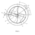
figure 3 est une vue de dessous du foret de lafigure 1 , - la
figure 4 est une vue de côté de la partie taillée du foret selon l'invention dans la direction E de lafigure 2 , - la
figure 5 est une vue similaire à lafigure 2 , illustrant un détail de réalisation du foret selon l'invention.
- the
figure 1 is a schematic side view of a forest according to the invention, - the
figure 2 is a detail view of the cut portion of the drill shown atfigure 1 , - the
figure 3 is a bottom view of the forest of thefigure 1 , - the
figure 4 is a side view of the cut portion of the drill according to the invention in the direction E of thefigure 2 , - the
figure 5 is a view similar to thefigure 2 , illustrating a detail of embodiment of the drill according to the invention.
Les
Ce foret céramique 1 comporte (voir
La partie taillée 3 du foret 1 comporte deux lèvres 8 et deux goujures 9, s'étendant en alternance autour de l'axe 4 depuis la queue 2 jusqu'à l'extrémité axiale libre 13b du foret 1. Les lèvres 8 et les goujures 9 sont enroulées de façon hélicoïdale autour de l'axe 4 avec un angle d'hélice 11 compris entre 25 et 40 degrés environ.The
Chaque lèvre 8 comporte un listel 12, destiné à glisser contre la paroi interne d'un trou à percer, et une surface de dégagement 13. Les listels 12 et les surfaces de dégagement 13 sont de forme hélicoïdale. Selon l'invention, chaque listel a une épaisseur 14 qui est inférieure ou égale au dixième du diamètre d de la partie taillée 3 du foret. Chaque goujure 9 comporte une face de coupe principale 16, adjacente à un listel 12. L'intersection du listel 12 et de la face de coupe principale 16 forme une arête appelée bord d'attaque 17 du listel 12.Each
Au niveau de l'extrémité axiale libre 13b du foret 1, chaque listel 12 se prolonge radialement, de l'extérieur du foret 1 vers son axe 4, par un chanfrein incurvé 25, suivi d'une face de dépouille principale 21. L'intersection entre chaque face de dépouille principale 21 et la goujure 9 correspondante forme une arête de coupe principale 18. Les deux arêtes de coupe principales 18 se prolongent, au niveau de la partie centrale du foret, par deux arêtes centrales 19. Les faces de dépouille principales 21 se prolongent, du côté des lèvres 8, par une face de contre-dépouille 30.At the free
Les faces de contre-dépouilles 30 présentent elles aussi un chanfrein 31, disposé dans le prolongement des chanfreins incurvés 25.The undercuts faces 30 also have a
La direction de coupe et la direction d'avance du foret sont repérées respectivement DirC et DirA.The cutting direction and the direction of advance of the drill are respectively marked DirC and DirA.
Soit A l'extrémité la plus éloignée de l'axe du foret d'une des arêtes de coupe principales 18. Afin que la description géométrique du foret selon l'invention soit la plus claire possible, les plans suivants sont définis :
- Pr : plan de référence du
foret 1, correspondant au plan passant par A, orthogonal à la direction de coupe DC et contenant l'axe 4 duforet 1, - Pf : plan de travail conventionnel du
foret 1, correspondant au plan passant par A, orthogonal au plan de référence Pr, parallèle à la direction d'avance DA et parallèle à l'axe duforet 1, - Pp : plan vers l'arrière du
foret 1, correspondant au plan passant par A, orthogonal aux plans de référence Pr et de travail conventionnel Pf, - Ps : plan d'arête du
foret 1, correspondant au plan tangent à l'arête de coupe principale 18 au point A, perpendiculaire au plan de référence Pr, - Pn : plan normal à l'arête de coupe principale 18, correspondant au plan perpendiculaire à l'arête de coupe principale 18 passant par A,
- Po : plan orthogonal du
foret 1, correspondant au plan passant par A, perpendiculaire aux plans de référence Pr et d'arête Ps.
- Pr: reference plane of the
drill 1, corresponding to the plane passing through A, orthogonal to the cutting direction DC and containing theaxis 4 of thedrill 1, - Pf: conventional working plane of the
drill 1, corresponding to the plane passing through A, orthogonal to the reference plane Pr, parallel to the direction of advance DA and parallel to the axis of thedrill bit 1, - Pp: plane towards the back of the
drill 1, corresponding to the plane passing through A, orthogonal to the reference planes Pr and of conventional work Pf, - Ps: plane of the edge of the
drill 1, corresponding to the plane tangential to themain cutting edge 18 at the point A, perpendicular to the reference plane Pr, - Pn: plane normal to the
main cutting edge 18, corresponding to the plane perpendicular to themain cutting edge 18 passing through A, - Po: orthogonal plane of the
drill 1, corresponding to the plane passing through A, perpendicular to the reference planes Pr and of edge Ps.
La géométrie du foret selon l'invention est telle que le plan orthogonal Po du foret est confondu avec le plan normal Pn à l'arête principale de coupe 18.The geometry of the drill according to the invention is such that the orthogonal plane Po of the drill is merged with the normal plane Pn at the
Dans le plan de référence Pr, correspondant à la vue de la
Dans le plan vers l'arrière Pp du foret 1, correspondant à la vue de la
Dans le plan de travail Pf du foret 1, correspondant à la vue de la
La partie taillée 3 du foret a une forme générale extérieure en tronc de cône. La base du tronc de cône est située au niveau de l'extrémité axiale libre 13b du foret et l'angle de conicité 26 de la partie taillée 3 peut aller jusqu'à 3 degrés environ.The
Deux faces de coupe secondaires 28, formées par la réalisation de deux piqûres 27 (
Les arêtes de coupe principales 18 et le bord d'attaque 17 de chaque listel 12 sont arrondis avec un rayon d'au moins 2 micromètres et pouvant aller jusqu'à 5 micromètres . Préférentiellement, ce rayon sera de l'ordre de 2 micromètres environ.The main cutting edges 18 and the leading
Pour fabriquer un foret selon l'invention, il n'est pas indispensable de connaître l'ensemble des caractéristiques géométriques mentionnées ci-dessus. A partir de certains angles caractéristiques, l'homme du métier, par exemple un fabriquant d'outils de coupe, saura déduire les autres caractéristiques, notamment grâce aux relations normalisées reliant les angles entre eux.To manufacture a drill according to the invention, it is not essential to know all the geometric characteristics mentioned above. From certain characteristic angles, the person skilled in the art, for example a manufacturer of cutting tools, will be able to deduce the other characteristics, in particular thanks to the standardized relations connecting the angles between them.
La géométrie du foret selon l'invention permet de réduire les efforts directement liés à la coupe tout en évitant le délaminage. Elle permet aussi de réduire les efforts résultant du frottement entre les listels 12 du foret et la paroi interne du trou à percer. Ainsi, le foret selon l'invention permet un perçage à très grande vitesse des matériaux composites car il résiste aux efforts importants produits dans ces conditions de perçage, tout en évitant le délaminage du matériau percé. Grâce à ce foret, il peut être de plus envisagé de percer des profondeurs supérieures au diamètre de l'outil sans que celui-ci ne s'use prématurément. Le délaminage du matériau composite est évité grâce à la présence des chanfreins incurvés 25. En effet, les extrémités radialement externes des chanfreins 25 usinant le matériau composite avant leurs extrémités radialement internes, les efforts appliqués par les chanfreins incurvés sur la matière à usiner sont globalement dirigés vers l'axe 4 du foret. Ainsi, la matière est prisonnière du foret, n'est pas repoussée vers l'extérieur et donc les différentes couches constitutives du matériau composite ne subissent pas d'effort tendant à les dissocier les unes des autres. Le délaminage du matériau est alors évité. La plage définie pour l'angle d'hélice 11 permet de loger sur la périphérie du foret 1 des goujures 9 suffisamment larges pour évacuer la quantité importante de copeaux produite lors de l'usinage à grande vitesse, sans diminuer la résistance du foret à la torsion. De plus, la présence de goujures 9 avec un angle d'hélice compris dans cette plage permet au foret selon l'invention de réaliser des perçages ayant une profondeur supérieure au diamètre du foret. Enfin, cette disposition, associée à la présence de l'angle αc entre les arêtes centrales 19 permettant un auto-centrage du foret 1, autorise la réalisation de perçages sans qu'une opération préliminaire de pointage soit nécessaire.The geometry of the drill according to the invention makes it possible to reduce the forces directly related to cutting while avoiding delamination. It also reduces the forces resulting from the friction between the
Comme illustré aux
Le matériau constituant la partie active de la partie taillée est préférentiellement une céramique à base d'oxyde d'alumine renforcée par des fibres en carbure de silicium (SiC), ou à base de zircone, de nitrure de silicium (dite SiAION) ou est une céramique dite "mixte" renforcée ou non, une céramique mixte étant composée de zirconium et de nitrure de silicium.The material constituting the active part of the cut part is preferably a ceramic based on alumina oxide reinforced with silicon carbide (SiC) fibers, or based on zirconia, silicon nitride (called SiAION) or is a so-called "mixed" ceramic reinforced or not, a mixed ceramic being composed of zirconium and silicon nitride.
Dans le cas d'un foret réalisé en deux parties, ces deux parties peuvent être liées entre elles par exemple par brasage. La partie taillée est alors en céramique tandis que la queue est réalisée dans un matériau de résilience supérieure à celle de la céramique pour mieux supporter les efforts appliqués sur le foret 1. Le matériau de la queue du foret peut par exemple être un carbure de tungstène.In the case of a drill made in two parts, these two parts may be bonded together for example by brazing. The cut portion is then ceramic while the tail is made of a resilient material greater than that of the ceramic to better withstand the forces applied to the
Pour illustrer la présente invention, un exemple de mise en oeuvre a été réalisé sur une pièce en résine d'époxy renforcée de carbone avec un foret céramique dont la partie taillée coupante était en AI203 et dont les caractéristiques géométriques, hors tolérances de fabrication, étaient les suivantes :
- l'angle αr de direction des arêtes de coupe principales 18 était de 60°,
- l'angle Ψr de direction complémentaire du
foret 1 était de 30°, - l'angle αc entre les deux arêtes centrales 19 était de 152°,
l'angle 25b formé par le segment reliant les points A et B et le plan Pp était de 6°,la distance 18a selon la direction radiale entre les points A de chaque arête de coupe principale 18 était de 12,7 mm,- l'angle de coupe vers l'arrière γp était de 17,9°,
- la largeur 21 b des faces de dépouille 21 était de 2,1 mm,
- l'angle γc entre une arête centrale 19 et le plan de référence Pr était de 37,1°,
- l'angle γj entre le segment de droite AD et le plan de référence Pr était de 74°,
- l'angle γk formé entre l'intersection d'une face de contre-
dépouille 30 et d'un chanfrein 31 et le plan de référence Pr était de 55°, - l'angle γg formé entre, d'une part la droite
passant par l'axe 4 du foret et l'intersection d'une goujure 9 et de la surface de dégagement 13 correspondante, et d'autre part par le plan Pp était de 80°, - l'angle γe entre chaque chanfrein incurvé 25 et le plan Pp était de 8°
- l'angle γi entre chaque chanfrein 31 et le plan Pp était de 2,1°,
- l'angle 27d entre le
segment 27b des piqûres 27et l'axe 4 du foret était de 5°, - l'angle 27e entre les
segments 27a et - l'angle de conicité 26 était de 1°,
- les arêtes de coupe principales 18 ainsi que le bord d'attaque 17 de chaque listel 12 étaient arrondis avec un rayon de 2 µm.
- the angle αr of direction of the main cutting edges 18 was 60 °,
- the angle Ψr complementary direction of the
drill 1 was 30 °, - the angle αc between the two
central edges 19 was 152 °, - the
angle 25b formed by the segment connecting the points A and B and the plane Pp was 6 °, - the
distance 18a in the radial direction between the points A of eachmain cutting edge 18 was 12.7 mm, - the rear cut angle γp was 17.9 °,
- the width 21b of the
flanks 21 was 2.1 mm, - the angle γc between a
central edge 19 and the reference plane Pr was 37.1 °, - the angle γj between the line segment AD and the reference plane Pr was 74 °,
- the angle γk formed between the intersection of an undercut
face 30 and achamfer 31 and the reference plane Pr was 55 °, - the angle γg formed between on the one hand the line passing through the
axis 4 of the drill and the intersection of aflute 9 and thecorresponding clearance surface 13, and on the other hand by the plane Pp was 80 °, - the angle γe between each
curved chamfer 25 and the plane Pp was 8 ° - the angle γi between each
chamfer 31 and the plane Pp was 2.1 °, - the angle 27d between the
segment 27b of thepunctures 27 and theaxis 4 of the drill was 5 °, - the
angle 27e between thesegments - the angle of
taper 26 was 1 °, - the main cutting edges 18 and the leading
edge 17 of eachlug 12 were rounded with a radius of 2 μm.
Le foret ainsi obtenu a permis de tester cette nouvelle géométrie et de confirmer les avantages qu'elle procure.The drill thus obtained made it possible to test this new geometry and to confirm the advantages it provides.
Le foret céramique 1 selon l'invention est particulièrement bien adapté au perçage de matériaux composites tels que des matériaux composites à fibres de carbone dont la matrice est une résine d'époxy. Son utilisation ne nécessite aucune adaptation particulière, notamment de la machine-outil, par rapport à l'utilisation d'un foret dont la partie active est en carbure de tungstène. Il est uniquement nécessaire que la machine-outil autorise des vitesses de rotation de l'outil suffisamment élevées et adaptées à l'usinage à grande vitesse. La plage d'utilisation du foret en terme de vitesse de coupe et d'avance peut être déterminée par une approche du type Coupe Outil Matière (COM). Pour des matériaux composites, le foret selon l'invention permet d'atteindre, en fonction du diamètre du foret, une vitesse de coupe périphérique comprise entre 600 et 1000 m/min, pour une avance comprise entre 0,05 et 0,20 mm/tour, sans user prématurément le foret ni délaminer le matériau à percer. Pour ces vitesses, le foret selon l'invention permet de réduire considérablement les contraintes s'exerçant sur ce dernier, qu'elles soient mécaniques (efforts de torsion et de compression) ou thermiques. Les contraintes thermiques sont diminuées en assurant une dissipation de la chaleur via les copeaux qui véhiculent rapidement cette énergie en dehors du perçage. L'utilisation du foret en dehors des plages de vitesse de coupe et d'avance préconisées est possible mais entraîne une dégradation accélérée de l'outil et donc une diminution de sa durée de vie. Le foret selon l'invention permet, pour le perçage de matériaux composites, de diviser le temps de perçage par dix. L'impact de la géométrie du foret sur sa durée de vie est notable puisque le nombre de trous percés par le même outil avant qu'il soit nécessaire d'en changer est multiplié par cinq.The
Selon une autre caractéristique de l'invention, le perçage est effectué à sec sans utilisation de lubrifiant et constitue une opération d'ébauche ne nécessitant pas d'opération de pointage préalable pour le centrage du foret.According to another characteristic of the invention, the drilling is carried out dry without the use of lubricant and constitutes a roughing operation that does not require a prior pointing operation for centering the drill bit.
Suivant l'état de surface requis et suivant les caractéristiques métallurgiques requises en périphérie immédiate du trou, une seule opération de perçage, sans opération de pointage préalable et sans opération ultérieure de finition, est suffisante pour réaliser le trou final.Depending on the required surface condition and the metallurgical characteristics required at the immediate periphery of the hole, a single drilling operation, without prior pointing operation and without subsequent finishing operation, is sufficient to achieve the final hole.
Compte tenu des vitesses de coupe et des avances élevées qui peuvent être atteintes grâce au foret selon l'invention, seules des machines spécifiques destinées à l'usinage grande vitesse et suffisamment rigides sont à même de donner un résultat pleinement satisfaisant en terme de qualité de perçage et de durée de vie de l'outil.Given the high cutting speeds and feed rates that can be achieved thanks to the drill according to the invention, only specific machines intended for high-speed machining and sufficiently rigid are able to give a fully satisfactory result in terms of quality of production. drilling and tool life.
Claims (18)
Applications Claiming Priority (1)
| Application Number | Priority Date | Filing Date | Title |
|---|---|---|---|
| FR0705457A FR2919212B1 (en) | 2007-07-26 | 2007-07-26 | CERAMIC DRILL FOR HIGH SPEED DRILLING OF COMPOSITE MATERIALS. |
Publications (2)
| Publication Number | Publication Date |
|---|---|
| EP2018918A1 true EP2018918A1 (en) | 2009-01-28 |
| EP2018918B1 EP2018918B1 (en) | 2010-01-27 |
Family
ID=39113965
Family Applications (1)
| Application Number | Title | Priority Date | Filing Date |
|---|---|---|---|
| EP08160909A Active EP2018918B1 (en) | 2007-07-26 | 2008-07-22 | Drill for high-speed perforation of composite materials |
Country Status (10)
| Country | Link |
|---|---|
| US (1) | US8206067B2 (en) |
| EP (1) | EP2018918B1 (en) |
| JP (1) | JP2009028895A (en) |
| CN (1) | CN101352766A (en) |
| CA (1) | CA2637652C (en) |
| DE (1) | DE602008000608D1 (en) |
| ES (1) | ES2339905T3 (en) |
| FR (1) | FR2919212B1 (en) |
| IL (1) | IL193030A (en) |
| RU (1) | RU2469820C2 (en) |
Cited By (2)
| Publication number | Priority date | Publication date | Assignee | Title |
|---|---|---|---|---|
| ITTO20100839A1 (en) * | 2010-10-15 | 2012-04-16 | Utensileria Navone S N C Di Navone Giovanni & C | DRILL BIT TIP. |
| CN105195793A (en) * | 2015-09-11 | 2015-12-30 | 沈阳航空航天大学 | Processing drill bit for fiber reinforced resin matrix composite |
Families Citing this family (35)
| Publication number | Priority date | Publication date | Assignee | Title |
|---|---|---|---|---|
| SE528917C2 (en) * | 2005-07-05 | 2007-03-13 | Sandvik Intellectual Property | Twist drill |
| GB2428611B (en) * | 2005-08-02 | 2007-10-03 | Dormer Tools | Twist drill |
| SE532432C2 (en) * | 2008-05-09 | 2010-01-19 | Sandvik Intellectual Property | Drill body with primary and secondary release surfaces |
| JP5603924B2 (en) | 2009-03-30 | 2014-10-08 | グーリング オーハーゲー | Multi-bevel step tool driven by rotation |
| US9539652B2 (en) | 2010-04-30 | 2017-01-10 | Kennametal Inc. | Rotary cutting tool having PCD cutting tip |
| CN102380892B (en) * | 2010-09-03 | 2014-04-02 | 北京航天新风机械设备有限责任公司 | Hole machining method of reinforced resin matrix composite prepreg of fiber fabric |
| JP5691424B2 (en) * | 2010-11-17 | 2015-04-01 | 株式会社不二越 | drill |
| US20120263548A1 (en) * | 2011-04-12 | 2012-10-18 | Richard Paul Harris | Drill bit |
| JP5945283B2 (en) * | 2011-12-27 | 2016-07-05 | 住友電気工業株式会社 | drill |
| CN102581356A (en) * | 2012-03-21 | 2012-07-18 | 锑玛(苏州)精密工具有限公司 | Internal cold drill |
| US8984991B1 (en) * | 2013-04-23 | 2015-03-24 | Brad A. English | Fastener removal device for dirty environments |
| WO2015026955A1 (en) | 2013-08-21 | 2015-02-26 | Scianamblo Michael J | Precessional drilling and reaming |
| CN103586636B (en) * | 2013-11-11 | 2016-01-06 | 中国南方航空工业(集团)有限公司 | The processing method of spout and the processing unit (plant) of spout |
| CN103737069B (en) * | 2013-12-09 | 2016-11-23 | 上海飞机制造有限公司 | The method for designing of cutter and its cutter for drilling composite element |
| JP6378493B2 (en) * | 2014-01-31 | 2018-08-22 | 旭ダイヤモンド工業株式会社 | drill |
| CN104107938A (en) * | 2014-05-16 | 2014-10-22 | 机械科学研究总院先进制造技术研究中心 | Novel tool special for cutting lost foam |
| CN104028812A (en) * | 2014-06-16 | 2014-09-10 | 同济大学 | Drill bit special for carbon fiber composite materials |
| RU2576356C1 (en) * | 2014-09-22 | 2016-02-27 | Сергей Николаевич Низов | Twist bit |
| CN104439432A (en) * | 2014-11-27 | 2015-03-25 | 苏州阿诺精密切削技术股份有限公司 | J-shaped seamed edge correction auger bit |
| RU2593559C2 (en) * | 2014-12-30 | 2016-08-10 | Федеральное государственное бюджетное образовательное учреждение высшего профессионального образования "Московский государственный технический университет имени Н.Э. Баумана" (МГТУ им. Н.Э. Баумана) | Method for drilling fibrous polymer composite materials and device for implementing thereof |
| USD833490S1 (en) * | 2015-05-13 | 2018-11-13 | Diager | Drill bit |
| USD900893S1 (en) | 2016-03-15 | 2020-11-03 | Brad A. English | Jagged tooth head fastener removal device for dirty environments |
| CN114191125A (en) * | 2016-03-21 | 2022-03-18 | 黄迪熙 | Detachable medical cutting tool |
| CN105856430A (en) * | 2016-06-03 | 2016-08-17 | 中国工程物理研究院激光聚变研究中心 | Punching device |
| TWI619572B (en) * | 2016-07-22 | 2018-04-01 | 創國興業有限公司 | Drill structure |
| US11117200B2 (en) | 2016-10-21 | 2021-09-14 | Kyocera Sgs Precision Tools, Inc. | Drills and methods of using the same |
| CN106583806A (en) * | 2016-11-11 | 2017-04-26 | 丹阳宝联五金制品有限公司 | Combined ceramic drill bit |
| CN106624080B (en) * | 2016-12-20 | 2018-10-16 | 大连理工大学 | A kind of micro- tooth Double-margin brill ream one drill bit of ladder |
| WO2019204644A1 (en) | 2018-04-18 | 2019-10-24 | Scianamblo Michael J | Bone matter collection apparatuses |
| WO2019244106A1 (en) | 2018-06-22 | 2019-12-26 | Maestro Logistics, Llc | A drill bit and method for making a drill bit |
| CN109227740B (en) * | 2018-09-05 | 2020-01-24 | 大连理工大学 | Method for manufacturing holes in carbon grid assembly of ion thruster |
| JP7375329B2 (en) * | 2019-04-17 | 2023-11-08 | 三菱マテリアル株式会社 | Drill |
| CN112974923A (en) * | 2019-12-13 | 2021-06-18 | 常州冶戈工具有限公司 | PCD (Poly Crystal Diamond) forming milling cutter for machining automobile inlay |
| CN112894996B (en) * | 2021-01-13 | 2022-10-14 | 沈阳航空航天大学 | Progressive cutting drill bit and CFRP hole making method based on progressive cutting drill bit |
| CN114700533A (en) * | 2022-03-29 | 2022-07-05 | 成都欧珀琅精密工具有限公司 | Special hole-making drill bit for composite material |
Citations (7)
| Publication number | Priority date | Publication date | Assignee | Title |
|---|---|---|---|---|
| US4529341A (en) * | 1982-09-29 | 1985-07-16 | Hughes Helicopters, Inc. | Drill bit for Kevlar laminates |
| EP0477093A1 (en) | 1990-09-20 | 1992-03-25 | Societe Nationale D'etude Et De Construction De Moteurs D'aviation, "S.N.E.C.M.A." | Milling cutter tool with body and head made out of different materials and method of making |
| EP0761352A1 (en) * | 1995-07-29 | 1997-03-12 | Black & Decker Inc. | A roll-forged drill bit |
| WO2001091960A1 (en) * | 2000-05-26 | 2001-12-06 | Nygaard Eero | Drill bit |
| DE10106035A1 (en) * | 2001-02-09 | 2002-08-29 | Scintilla Ag | Drill bit for drilling metal has at least one cross surface formed on drill bit head |
| FR2861001A1 (en) | 2003-10-16 | 2005-04-22 | Snecma Moteurs | CERAMIC DRILL FOR HIGH SPEED DRILLING |
| WO2007015095A1 (en) * | 2005-08-02 | 2007-02-08 | Dormer Tools Limited | Twist drill |
Family Cites Families (17)
| Publication number | Priority date | Publication date | Assignee | Title |
|---|---|---|---|---|
| US2230645A (en) * | 1938-02-01 | 1941-02-04 | Western Electric Co | Drill |
| US2332295A (en) * | 1941-11-07 | 1943-10-19 | Western Electric Co | Drill |
| SU512007A1 (en) * | 1972-11-04 | 1976-04-30 | Владимирский политехнический институт | Spiral drill |
| US4209275A (en) * | 1978-10-30 | 1980-06-24 | Kim Joo B | Twist drill |
| DE3344620A1 (en) * | 1983-12-09 | 1985-06-20 | Hartmetallwerkzeugfabrik Andreas Maier GmbH + Co KG, 7959 Schwendi | MULTI-CUTTING DRILL |
| US4968193A (en) * | 1986-08-18 | 1990-11-06 | Black & Decker Corporation | Self-centering drill bit with pilot tip |
| US5288183A (en) * | 1986-08-18 | 1994-02-22 | Black & Decker Inc. | Self-centering drill bit with pilot tip |
| JPH02237712A (en) * | 1989-03-09 | 1990-09-20 | Mitsubishi Heavy Ind Ltd | Twist drill |
| JPH02237711A (en) * | 1989-03-09 | 1990-09-20 | Mitsubishi Heavy Ind Ltd | Twist drill |
| US5236291A (en) * | 1992-08-31 | 1993-08-17 | General Motors Corporation | Multi-tooth drill with improved chisel edge |
| SE507842C2 (en) * | 1992-09-24 | 1998-07-20 | Sandvik Ab | Drill |
| JP3307809B2 (en) * | 1995-10-05 | 2002-07-24 | 兼房株式会社 | Rotary tool with shank |
| IL123858A (en) * | 1998-03-27 | 2003-05-29 | Iscar Ltd | Drilling head |
| DE20304580U1 (en) * | 2003-03-21 | 2004-08-12 | Gühring, Jörg, Dr. | drill |
| EP1512476B1 (en) * | 2003-09-08 | 2013-10-09 | Black & Decker Inc. | Self-centering drill bit with pilot tip |
| DE102004026014B4 (en) * | 2004-05-27 | 2008-04-17 | Horst Miebach Gmbh | twist drill |
| SE532432C2 (en) * | 2008-05-09 | 2010-01-19 | Sandvik Intellectual Property | Drill body with primary and secondary release surfaces |
-
2007
- 2007-07-26 FR FR0705457A patent/FR2919212B1/en not_active Expired - Fee Related
-
2008
- 2008-07-22 ES ES08160909T patent/ES2339905T3/en active Active
- 2008-07-22 EP EP08160909A patent/EP2018918B1/en active Active
- 2008-07-22 DE DE602008000608T patent/DE602008000608D1/en active Active
- 2008-07-24 IL IL193030A patent/IL193030A/en not_active IP Right Cessation
- 2008-07-25 RU RU2008130814/02A patent/RU2469820C2/en active
- 2008-07-25 JP JP2008191757A patent/JP2009028895A/en active Pending
- 2008-07-25 CA CA2637652A patent/CA2637652C/en active Active
- 2008-07-25 US US12/180,075 patent/US8206067B2/en active Active
- 2008-07-28 CN CN200810134628.5A patent/CN101352766A/en active Pending
Patent Citations (7)
| Publication number | Priority date | Publication date | Assignee | Title |
|---|---|---|---|---|
| US4529341A (en) * | 1982-09-29 | 1985-07-16 | Hughes Helicopters, Inc. | Drill bit for Kevlar laminates |
| EP0477093A1 (en) | 1990-09-20 | 1992-03-25 | Societe Nationale D'etude Et De Construction De Moteurs D'aviation, "S.N.E.C.M.A." | Milling cutter tool with body and head made out of different materials and method of making |
| EP0761352A1 (en) * | 1995-07-29 | 1997-03-12 | Black & Decker Inc. | A roll-forged drill bit |
| WO2001091960A1 (en) * | 2000-05-26 | 2001-12-06 | Nygaard Eero | Drill bit |
| DE10106035A1 (en) * | 2001-02-09 | 2002-08-29 | Scintilla Ag | Drill bit for drilling metal has at least one cross surface formed on drill bit head |
| FR2861001A1 (en) | 2003-10-16 | 2005-04-22 | Snecma Moteurs | CERAMIC DRILL FOR HIGH SPEED DRILLING |
| WO2007015095A1 (en) * | 2005-08-02 | 2007-02-08 | Dormer Tools Limited | Twist drill |
Cited By (4)
| Publication number | Priority date | Publication date | Assignee | Title |
|---|---|---|---|---|
| ITTO20100839A1 (en) * | 2010-10-15 | 2012-04-16 | Utensileria Navone S N C Di Navone Giovanni & C | DRILL BIT TIP. |
| EP2441544A1 (en) | 2010-10-15 | 2012-04-18 | Utensileria Navone S.n.c. di Navone Giovanni & C. | Tip for drilling tool. |
| CN105195793A (en) * | 2015-09-11 | 2015-12-30 | 沈阳航空航天大学 | Processing drill bit for fiber reinforced resin matrix composite |
| CN105195793B (en) * | 2015-09-11 | 2017-11-10 | 沈阳航空航天大学 | A kind of processing drill for fiber-reinforced resin matrix compound material |
Also Published As
| Publication number | Publication date |
|---|---|
| CN101352766A (en) | 2009-01-28 |
| DE602008000608D1 (en) | 2010-03-18 |
| US20090028654A1 (en) | 2009-01-29 |
| RU2469820C2 (en) | 2012-12-20 |
| IL193030A (en) | 2011-12-29 |
| CA2637652A1 (en) | 2009-01-26 |
| RU2008130814A (en) | 2010-01-27 |
| ES2339905T3 (en) | 2010-05-26 |
| EP2018918B1 (en) | 2010-01-27 |
| US8206067B2 (en) | 2012-06-26 |
| FR2919212B1 (en) | 2009-12-25 |
| FR2919212A1 (en) | 2009-01-30 |
| JP2009028895A (en) | 2009-02-12 |
| CA2637652C (en) | 2015-03-24 |
Similar Documents
| Publication | Publication Date | Title |
|---|---|---|
| EP2018918B1 (en) | Drill for high-speed perforation of composite materials | |
| EP1524055B1 (en) | Ceramics drill for high speed drilling and drilling process | |
| EP2030712B1 (en) | Groove cutter for machining with course feed and reduced depth of cut | |
| CA2651021C (en) | Surfacing and contour milling tool for high-speed machining of composite material parts | |
| JP2009028895A5 (en) | ||
| FR2874342A1 (en) | CARBIDE DRILL FOR DRILLING A HOLE WITH A REDUCED DEGREE OF NUTS | |
| EP2457678B1 (en) | Bi-material one-piece cutting tool | |
| FR2975027A1 (en) | Tool for drilling hole in workpiece i.e. casing flange, of turbojet engine of aircraft made of composite material with organic matrix, has polishing and abrasive region that is fine grained to complete drilling of coarse hole | |
| FR2656554A1 (en) | Precision drilling tool for composite materials | |
| FR2552354A1 (en) | ANNULAR CUTTING TOOL FOR DRILLING HOLES | |
| JP5914446B2 (en) | Cutting tool and workpiece machining method using the same | |
| EP3003619B1 (en) | Rotary cutting tool with a cutting edge made of several materials | |
| FR2639565A1 (en) | HELICOIDAL FOREST | |
| EP3962685A1 (en) | Cutting tool with integrated lubrication | |
| FR2994871A1 (en) | Cylindrical drilling tool for drilling casing flange of turbojet of aircraft, has completion part placed behind blank part and covered with abrasive material allowing completion of hole, where blank part comprises ring in extension of axis | |
| KR101633227B1 (en) | Drill tool for processing composite material | |
| EP0121634B1 (en) | Reamer, particularly suitable for drilling composite materials | |
| CH716141A2 (en) | Integrated lubricating cutting tool with directional coolant ring. | |
| EP0936014B1 (en) | Schneidwerkzeug, insbesondere Bohrer,mit verbesserter Geometrie | |
| EP2800649B1 (en) | Tool for machining a wall of a workpiece, particularly of composite material | |
| CH716140A2 (en) | Integrated lubricating cutting tool. | |
| FR2747950A1 (en) | Drill for motor vehicle brake disc rotors | |
| FR2954197A1 (en) | Drill for use in vibrating drilling system to pierce piece i.e. aeronautical pieces, has tip provided with two cutting edges, where width of core at tip is provided between two and five cm of external diameter of main body |
Legal Events
| Date | Code | Title | Description |
|---|---|---|---|
| PUAI | Public reference made under article 153(3) epc to a published international application that has entered the european phase |
Free format text: ORIGINAL CODE: 0009012 |
|
| 17P | Request for examination filed |
Effective date: 20080722 |
|
| AK | Designated contracting states |
Kind code of ref document: A1 Designated state(s): AT BE BG CH CY CZ DE DK EE ES FI FR GB GR HR HU IE IS IT LI LT LU LV MC MT NL NO PL PT RO SE SI SK TR |
|
| AX | Request for extension of the european patent |
Extension state: AL BA MK RS |
|
| RTI1 | Title (correction) |
Free format text: DRILL FOR HIGH-SPEED PERFORATION OF COMPOSITE MATERIALS |
|
| GRAP | Despatch of communication of intention to grant a patent |
Free format text: ORIGINAL CODE: EPIDOSNIGR1 |
|
| AKX | Designation fees paid |
Designated state(s): DE ES FR GB IT |
|
| GRAS | Grant fee paid |
Free format text: ORIGINAL CODE: EPIDOSNIGR3 |
|
| GRAA | (expected) grant |
Free format text: ORIGINAL CODE: 0009210 |
|
| AK | Designated contracting states |
Kind code of ref document: B1 Designated state(s): DE ES FR GB IT |
|
| REG | Reference to a national code |
Ref country code: GB Ref legal event code: FG4D Free format text: NOT ENGLISH |
|
| REF | Corresponds to: |
Ref document number: 602008000608 Country of ref document: DE Date of ref document: 20100318 Kind code of ref document: P |
|
| REG | Reference to a national code |
Ref country code: ES Ref legal event code: FG2A Ref document number: 2339905 Country of ref document: ES Kind code of ref document: T3 |
|
| PLBE | No opposition filed within time limit |
Free format text: ORIGINAL CODE: 0009261 |
|
| STAA | Information on the status of an ep patent application or granted ep patent |
Free format text: STATUS: NO OPPOSITION FILED WITHIN TIME LIMIT |
|
| 26N | No opposition filed |
Effective date: 20101028 |
|
| PG25 | Lapsed in a contracting state [announced via postgrant information from national office to epo] |
Ref country code: IT Free format text: LAPSE BECAUSE OF FAILURE TO SUBMIT A TRANSLATION OF THE DESCRIPTION OR TO PAY THE FEE WITHIN THE PRESCRIBED TIME-LIMIT Effective date: 20100127 |
|
| PGFP | Annual fee paid to national office [announced via postgrant information from national office to epo] |
Ref country code: ES Payment date: 20120716 Year of fee payment: 5 |
|
| REG | Reference to a national code |
Ref country code: ES Ref legal event code: FD2A Effective date: 20140908 |
|
| PG25 | Lapsed in a contracting state [announced via postgrant information from national office to epo] |
Ref country code: ES Free format text: LAPSE BECAUSE OF NON-PAYMENT OF DUE FEES Effective date: 20130723 |
|
| REG | Reference to a national code |
Ref country code: FR Ref legal event code: PLFP Year of fee payment: 9 |
|
| REG | Reference to a national code |
Ref country code: FR Ref legal event code: PLFP Year of fee payment: 10 |
|
| REG | Reference to a national code |
Ref country code: FR Ref legal event code: CD Owner name: SAFRAN AIRCRAFT ENGINES, FR Effective date: 20170719 |
|
| REG | Reference to a national code |
Ref country code: FR Ref legal event code: PLFP Year of fee payment: 11 |
|
| PGFP | Annual fee paid to national office [announced via postgrant information from national office to epo] |
Ref country code: FR Payment date: 20230621 Year of fee payment: 16 |
|
| PGFP | Annual fee paid to national office [announced via postgrant information from national office to epo] |
Ref country code: GB Payment date: 20230620 Year of fee payment: 16 |
|
| PGFP | Annual fee paid to national office [announced via postgrant information from national office to epo] |
Ref country code: DE Payment date: 20230620 Year of fee payment: 16 |