EP2018918A1 - Keramikbohrer zum Hochgeschwindigkeitsbohren von Verbundstoffen - Google Patents
Keramikbohrer zum Hochgeschwindigkeitsbohren von Verbundstoffen Download PDFInfo
- Publication number
- EP2018918A1 EP2018918A1 EP08160909A EP08160909A EP2018918A1 EP 2018918 A1 EP2018918 A1 EP 2018918A1 EP 08160909 A EP08160909 A EP 08160909A EP 08160909 A EP08160909 A EP 08160909A EP 2018918 A1 EP2018918 A1 EP 2018918A1
- Authority
- EP
- European Patent Office
- Prior art keywords
- drill
- angle
- ceramic
- plane
- drilling
- Prior art date
- Legal status (The legal status is an assumption and is not a legal conclusion. Google has not performed a legal analysis and makes no representation as to the accuracy of the status listed.)
- Granted
Links
Images


Classifications
-
- B—PERFORMING OPERATIONS; TRANSPORTING
- B23—MACHINE TOOLS; METAL-WORKING NOT OTHERWISE PROVIDED FOR
- B23B—TURNING; BORING
- B23B51/00—Tools for drilling machines
- B23B51/0081—Conical drills
-
- B—PERFORMING OPERATIONS; TRANSPORTING
- B23—MACHINE TOOLS; METAL-WORKING NOT OTHERWISE PROVIDED FOR
- B23B—TURNING; BORING
- B23B51/00—Tools for drilling machines
- B23B51/02—Twist drills
-
- B—PERFORMING OPERATIONS; TRANSPORTING
- B23—MACHINE TOOLS; METAL-WORKING NOT OTHERWISE PROVIDED FOR
- B23B—TURNING; BORING
- B23B2215/00—Details of workpieces
- B23B2215/04—Aircraft components
-
- B—PERFORMING OPERATIONS; TRANSPORTING
- B23—MACHINE TOOLS; METAL-WORKING NOT OTHERWISE PROVIDED FOR
- B23B—TURNING; BORING
- B23B2226/00—Materials of tools or workpieces not comprising a metal
- B23B2226/18—Ceramic
-
- B—PERFORMING OPERATIONS; TRANSPORTING
- B23—MACHINE TOOLS; METAL-WORKING NOT OTHERWISE PROVIDED FOR
- B23B—TURNING; BORING
- B23B2226/00—Materials of tools or workpieces not comprising a metal
- B23B2226/27—Composites
-
- B—PERFORMING OPERATIONS; TRANSPORTING
- B23—MACHINE TOOLS; METAL-WORKING NOT OTHERWISE PROVIDED FOR
- B23B—TURNING; BORING
- B23B2226/00—Materials of tools or workpieces not comprising a metal
- B23B2226/27—Composites
- B23B2226/275—Carbon fibre reinforced carbon composites
-
- B—PERFORMING OPERATIONS; TRANSPORTING
- B23—MACHINE TOOLS; METAL-WORKING NOT OTHERWISE PROVIDED FOR
- B23B—TURNING; BORING
- B23B2226/00—Materials of tools or workpieces not comprising a metal
- B23B2226/36—Epoxy
-
- B—PERFORMING OPERATIONS; TRANSPORTING
- B23—MACHINE TOOLS; METAL-WORKING NOT OTHERWISE PROVIDED FOR
- B23B—TURNING; BORING
- B23B2251/00—Details of tools for drilling machines
- B23B2251/04—Angles, e.g. cutting angles
-
- B—PERFORMING OPERATIONS; TRANSPORTING
- B23—MACHINE TOOLS; METAL-WORKING NOT OTHERWISE PROVIDED FOR
- B23B—TURNING; BORING
- B23B2251/00—Details of tools for drilling machines
- B23B2251/14—Configuration of the cutting part, i.e. the main cutting edges
-
- B—PERFORMING OPERATIONS; TRANSPORTING
- B23—MACHINE TOOLS; METAL-WORKING NOT OTHERWISE PROVIDED FOR
- B23B—TURNING; BORING
- B23B2251/00—Details of tools for drilling machines
- B23B2251/18—Configuration of the drill point
-
- B—PERFORMING OPERATIONS; TRANSPORTING
- B23—MACHINE TOOLS; METAL-WORKING NOT OTHERWISE PROVIDED FOR
- B23B—TURNING; BORING
- B23B2270/00—Details of turning, boring or drilling machines, processes or tools not otherwise provided for
- B23B2270/54—Methods of turning, boring or drilling not otherwise provided for
-
- Y—GENERAL TAGGING OF NEW TECHNOLOGICAL DEVELOPMENTS; GENERAL TAGGING OF CROSS-SECTIONAL TECHNOLOGIES SPANNING OVER SEVERAL SECTIONS OF THE IPC; TECHNICAL SUBJECTS COVERED BY FORMER USPC CROSS-REFERENCE ART COLLECTIONS [XRACs] AND DIGESTS
- Y10—TECHNICAL SUBJECTS COVERED BY FORMER USPC
- Y10T—TECHNICAL SUBJECTS COVERED BY FORMER US CLASSIFICATION
- Y10T408/00—Cutting by use of rotating axially moving tool
- Y10T408/03—Processes
-
- Y—GENERAL TAGGING OF NEW TECHNOLOGICAL DEVELOPMENTS; GENERAL TAGGING OF CROSS-SECTIONAL TECHNOLOGIES SPANNING OVER SEVERAL SECTIONS OF THE IPC; TECHNICAL SUBJECTS COVERED BY FORMER USPC CROSS-REFERENCE ART COLLECTIONS [XRACs] AND DIGESTS
- Y10—TECHNICAL SUBJECTS COVERED BY FORMER USPC
- Y10T—TECHNICAL SUBJECTS COVERED BY FORMER US CLASSIFICATION
- Y10T408/00—Cutting by use of rotating axially moving tool
- Y10T408/78—Tool of specific diverse material
-
- Y—GENERAL TAGGING OF NEW TECHNOLOGICAL DEVELOPMENTS; GENERAL TAGGING OF CROSS-SECTIONAL TECHNOLOGIES SPANNING OVER SEVERAL SECTIONS OF THE IPC; TECHNICAL SUBJECTS COVERED BY FORMER USPC CROSS-REFERENCE ART COLLECTIONS [XRACs] AND DIGESTS
- Y10—TECHNICAL SUBJECTS COVERED BY FORMER USPC
- Y10T—TECHNICAL SUBJECTS COVERED BY FORMER US CLASSIFICATION
- Y10T408/00—Cutting by use of rotating axially moving tool
- Y10T408/89—Tool or Tool with support
- Y10T408/899—Having inversely angled cutting edge
-
- Y—GENERAL TAGGING OF NEW TECHNOLOGICAL DEVELOPMENTS; GENERAL TAGGING OF CROSS-SECTIONAL TECHNOLOGIES SPANNING OVER SEVERAL SECTIONS OF THE IPC; TECHNICAL SUBJECTS COVERED BY FORMER USPC CROSS-REFERENCE ART COLLECTIONS [XRACs] AND DIGESTS
- Y10—TECHNICAL SUBJECTS COVERED BY FORMER USPC
- Y10T—TECHNICAL SUBJECTS COVERED BY FORMER US CLASSIFICATION
- Y10T408/00—Cutting by use of rotating axially moving tool
- Y10T408/89—Tool or Tool with support
- Y10T408/909—Having peripherally spaced cutting edges
- Y10T408/9095—Having peripherally spaced cutting edges with axially extending relief channel
- Y10T408/9097—Spiral channel
Definitions
- the invention relates to a drill made of ceramic material. It finds a particular application for the drilling at very high speed of composite material parts, especially carbon fiber composite material whose matrix is an epoxy resin. This type of material, thanks to its high mechanical characteristics and low density, is widely used in fields such as aeronautics.
- Ceramics because of their high hardness and high resistance to high temperatures, are experiencing a development in the manufacture of cutting tools.
- Known ceramic cutting tools such as those described in the patent document EP 0 477 093 are generally milling or turning tools and allow to perform high speed machining on materials of great hardness.
- the constraints that can be applied on a drill bit are greater than those that can be applied to a cutter during a drilling operation. a milling operation. These constraints make it more difficult to use ceramic drills to perform very high-speed drilling in materials of high hardness such as metal superalloys.
- the patent FR 2 861 001 provides a solution to this problem by proposing a ceramic drill whose particular geometry is suitable for drilling at very high speed in metal materials of great hardness. This geometry makes it possible to overcome the problems related to the lower resistance to torsion of a ceramic drill compared to steel drills and reach peripheral cutting speeds greater than 400 meters / minute, while guaranteeing a long life. of satisfactory forest life.
- the torsional forces applied to the drills are increasingly important, firstly because the outer surface of the drill rubbing against the cylindrical inner surface of the borehole increases. , but also because, for high drilling speeds, the drill must be able to efficiently remove a large amount of chips, which can cause stuffing in the drill, increasing the torsional forces applied to the drill bit and the risks of breaking it.
- the cutting edge of the drill must be able to withstand a large cutting speed gradient, since in its center the cutting speed is zero and it increases gradually to reach a maximum on the periphery of the forest.
- Another constraint related to the machining, and in particular drilling, of composite materials is that the operation must be performed while maintaining the integrity of the pierced material.
- the conventional drills exert efforts on the internal cylindrical surface of the drilled holes globally directed from the drill to the material to be machined. This is causing delamination of the material, which is absolutely necessary to avoid.
- the drills known from the prior art are not suitable for machining composite materials at high speed and suitably, particularly carbon fiber composite materials whose matrix is an epoxy resin.
- the drill described in the patent FR 2 861 001 is well suited for high speed drilling of metal materials of great hardness, but is not suitable for composite materials, causing in this case a delamination of the material to be machined.
- the object of the invention is to avoid the above-mentioned drawbacks and to provide a technically simple and inexpensive solution, making it possible to improve the performance of ceramic drills and to pierce at very high speed composite materials such as composite materials.
- composite materials such as composite materials.
- the invention proposes a new type of drill capable of achieving a specific cutting energy of between 30 and 50 W / cm 3 / min, comprising an active part made of ceramic material and whose geometry is optimized and suitable for drilling with a large diameter. speed of composite materials.
- This new type of The drill is able to withstand the mechanical forces generated by the material machined at these speeds.
- the subject of the invention is a drill comprising a shank, a portion cut in the form of a truncated cone extending up to the shank and whose base is located at a free axial end of the drill, said end having at least two main cutting edges interconnected by two central edges, said cut portion having two lips and two flutes extending helically alternately about a longitudinal axis of rotation of the drill, the lips and the flutes extending from the free axial end to the drill shank, each lip having a ridge and flute having a main cutting face adjacent to a ridge and a main ridge, which ridge intersects with a face of main draft at the free axial end of the drill, the main flanks each extending, on the side of the lips, by a face of against-d puille, two punctures extending from the central edges to the periphery of the drill and forming two secondary cutting faces, at least one end portion of the cut portion of the drill being made of ceramic material, said drill being remarkable in that each
- flanks and undercuts of the drill head are extended, radially outward, by, respectively, a first curved chamfer forming a flank surface and a second chamfer forming an undercut surface. . Inward bending of the first and second chamfers avoids delamination of the composite material drilled by the drill bit.
- the invention also relates to a method of drilling composite materials using a ceramic drill bit of the type described above, wherein the drill has a peripheral cutting speed of between 600 and 1000 m / min.
- the drill has an advance of between 0.05 and 0.20 mm / revolution.
- the drilling can be carried out dry, without prior centering operation. A single drilling operation may be sufficient to achieve the final hole.
- the depth of the drilling may be greater than the diameter of the cut portion of the drill bit.
- the material to be pierced is a carbon fiber composite material whose matrix is an epoxy resin.
- the Figures 1 to 5 represent by way of example a ceramic monoblock drill for high-speed drilling of composite materials, in particular composite carbon fiber materials whose matrix is an epoxy resin.
- This ceramic drill bit 1 (see figure 1 ) a cylindrical tail 2 or conical and a cut portion 3 extending from the tail in the axis 4 of the drill to a free axial end 13b.
- the shank may be smooth as illustrated herein or have an annular groove (not shown) for clamping the drill into the chuck of a machine tool (not shown).
- the free axial end 6 of the tail ends with a chamfer 7 to facilitate its introduction into the mandrel of the machine tool.
- the tail 2 and the cut portion 3 of the drill bit 1 can be connected to each other by a chamfer 5, necessary when the outer diameters of the tail and the cut portion are different.
- the cut portion 3 of the drill 1 comprises two lips 8 and two flutes 9, extending alternately about the axis 4 from the shank 2 to the free axial end 13b of the drill 1.
- the lips 8 and the flutes 9 are wound helically about the axis 4 with a helix angle 11 of between 25 and 40 degrees.
- Each lip 8 comprises a strip 12, intended to slide against the inner wall of a hole to be drilled, and a release surface 13.
- the strips 12 and the clearance surfaces 13 are helically shaped.
- each strip has a thickness 14 which is less than or equal to one tenth of the diameter d of the cut portion 3 of the drill.
- Each flute 9 has a main cutting face 16, adjacent to a strip 12. The intersection of the strip 12 and the main cutting face 16 forms an edge called leading edge 17 of the strip 12.
- each strip 12 extends radially from the outside of the drill 1 towards its axis 4 by a curved chamfer 25, followed by a main clearance face 21.
- intersection between each main draft face 21 and the corresponding flute 9 forms a main cutting edge 18.
- the two main cutting edges 18 extend at the central portion of the drill, by two central ridges 19.
- the flanks main 21 extend, on the side of the lips 8, by an undercut face 30.
- the undercuts faces 30 also have a chamfer 31 disposed in the extension of the curved chamfers 25.
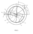
- the cutting direction and the direction of advance of the drill are respectively marked DirC and DirA.
- the geometry of the drill according to the invention is such that the orthogonal plane Po of the drill is merged with the normal plane Pn at the main cutting edge 18.
- each edge plane Ps forms with the work plane Pf an angle ⁇ r, called the direction angle of the main cutting edge 18, between 55 and 65 degrees. Furthermore, each edge plane Ps forms with the rearward plane Pp corresponding to an angle ⁇ r, called complementary steering angle of the drill 1, of between 27 and 37 degrees. The two central edges 19 form between them an angle ⁇ c between 142 and 162 degrees.
- the edge formed by the intersection between a curved chamfer 25 and the corresponding flute 9 is inclined at an angle 25b with respect to the plane Pp, so that the point B corresponding to the radially external end this edge is farther away from the shank 3 of the drill than the point A.
- the angle 25b is between 3 and 9 degrees approximately.
- the distance 18a in the radial direction between the points A of each main cutting edge 18 is between the diameter d of the cut portion 3 minus 2 mm and the diameter d plus 2 mm.
- each main cutting edge 18 forms an angle ⁇ p with the reference plane Pr.
- the angle ⁇ p is called the cutting angle towards the rear of the drill 1 and is between approximately 13 and 23 degrees.
- the flanks 21 have a width 21b of between 1 and 4 mm.
- Each central edge 19 forms with the reference plane Pr an angle ⁇ c between 32 and 42 degrees approximately.
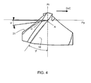
- the intersection between each curved chamfer 25 and the chamfer 31 made on the corresponding undercut face 30 forms a line segment whose ends are marked C and D, C being the end furthest from the axis 4 of the forest.
- the line segment AB of a curved chamfer 25, B corresponding to the fourth vertex of the curved chamfer forms with the reference plane Pr an angle ⁇ i of between approximately 2 and 4 degrees.
- the line segment AD forms with the reference plane Pr an angle ⁇ j between 69 and 79 degrees approximately.
- the intersection between each undercut face 30 and the corresponding chamfer 31 forms with the reference plane Pr an angle ⁇ k between about 50 and 60 degrees.
- the straight line passing through the axis 4 of the drill and by the intersection between a flute 9 and the corresponding clearance surface 13 forms, with the plane Pr, an angle ⁇ g of between approximately 60 and 90 degrees. .
- each main cutting face 16 forms with the reference plane Pr an angle ⁇ f, called the lateral cutting angle of the drill bit 1
- a positive angle or Negative cutting is determined by the orientation of the main cutting face 16 with respect to the cutting direction DirC: when the cutting face is inclined from the cutting edge to the cutting direction DirC, the cutting angle is said to be negative, and conversely, when the cutting face 16 is inclined from the cutting edge in the opposite direction to the cutting direction DirC, the cutting angle ⁇ f is positive.
- the cutting angle ⁇ f of the drill 1 is positive.
- each curved chamfer 25 forms with the rearward plane Pp of the drill 1 an angle ⁇ e of between about 6 and 10 degrees.
- the cut portion 3 of the drill has a generally outer truncated cone shape.
- the base of the truncated cone is located at the free axial end 13b of the drill and the conical angle 26 of the cut portion 3 can be up to about 3 degrees.
- Two secondary cutting faces 28, formed by making two pits 27 extend from the central edges 19 towards the periphery of the drill 1.
- the pits 27 are delimited by two straight line segments: a first line segment 27a starting from the intersection between a main cutting edge 18 and the edge corresponding central 19 and a second line segment forming the intersection between the puncture 27 and the adjacent undercut face 30.
- the segments 27a and 27b are interconnected by a curvilinear portion 27c.
- the segment 27b forms an angle 27d relative to the axis 4 of the drill between 1 and about 15 degrees.
- the segments 27a and 27b form between them an angle 27e of between 25 and 35 degrees approximately.
- each lug 12 is rounded with a radius of at least 2 microns and up to 5 microns. Preferably, this radius will be of the order of about 2 micrometers.
- the geometry of the drill according to the invention makes it possible to reduce the forces directly related to cutting while avoiding delamination. It also reduces the forces resulting from the friction between the listels 12 of the drill and the inner wall of the hole to be drilled.
- the drill according to the invention allows very high speed drilling of composite materials because it withstands the high forces produced in these drilling conditions, while avoiding the delamination of the pierced material. With this drill, it can be further considered to drill depths greater than the diameter of the tool without it wears prematurely. The delamination of the composite material is avoided thanks to the presence of the curved chamfers 25.
- the radially outer ends of the chamfers 25 machining the composite material before their radially inner ends, the forces applied by the curved chamfers on the material to be machined are globally directed towards the axis 4 of the drill.
- the material is trapped in the drill, is not pushed outwardly and therefore the various constituent layers of the composite material do not undergo any effort to separate them from each other.
- the delamination of the material is then avoided.
- the range defined for the helix angle 11 makes it possible to accommodate on the periphery of the drill 1 flutes 9 which are large enough to evacuate the large amount of chips produced during high speed machining, without reducing the resistance of the drill to the torsion.
- the drill can be monobloc, that is to say that the tail 2 and the cut portion 3 are made of the same ceramic material and in one piece.
- the drill can also consist of two parts made of different materials, one for the tail and the other for the part active, ie the cut part.
- the cut portion of the drill bit may also be composed of two different materials: the portion near the free axial end of the drill is then ceramic material, while the remaining portion may be in the same material as the tail.
- the material constituting the active part of the cut part is preferably a ceramic based on alumina oxide reinforced with silicon carbide (SiC) fibers, or based on zirconia, silicon nitride (called SiAION) or is a so-called "mixed" ceramic reinforced or not, a mixed ceramic being composed of zirconium and silicon nitride.
- SiC silicon carbide
- SiAION silicon nitride
- these two parts may be bonded together for example by brazing.
- the cut portion is then ceramic while the tail is made of a resilient material greater than that of the ceramic to better withstand the forces applied to the drill 1.
- the material of the drill shank may for example be a tungsten carbide .
- the ceramic drill bit 1 according to the invention is particularly well suited to piercing composite materials such as composite carbon fiber materials whose matrix is an epoxy resin. Its use does not require any particular adaptation, especially of the machine tool, compared to the use of a drill whose active part is tungsten carbide. It is only necessary that the machine tool allows tool rotation speeds that are sufficiently high and suitable for high speed machining.
- the range of use of the drill in terms of cutting speed and feed rate can be determined by an approach of the type Cut Material Tool (COM).
- COM Cut Material Tool
- the drill according to the invention makes it possible to achieve, depending on the diameter of the drill, a peripheral cutting speed of between 600 and 1000 m / min, for an advance of between 0.05 and 0.20 mm.
- the drill according to the invention makes it possible to reduce considerably the constraints exerted on the latter, whether mechanical (torsional and compressive forces) or thermal.
- the thermal stresses are reduced by ensuring heat dissipation via the chips that quickly convey this energy outside the piercing.
- the use of the drill outside the recommended cutting speed and advance speed ranges is possible but leads to accelerated degradation of the tool and thus a decrease in its life.
- the drill according to the invention makes it possible, for drilling composite materials, to divide the drilling time by ten. The impact of the geometry of the drill on its life is significant since the number of holes drilled by the same tool before it is necessary to change is multiplied by five.
- the drilling is carried out dry without the use of lubricant and constitutes a roughing operation that does not require a prior pointing operation for centering the drill bit.
Landscapes
- Engineering & Computer Science (AREA)
- Mechanical Engineering (AREA)
- Drilling Tools (AREA)
- Processing Of Stones Or Stones Resemblance Materials (AREA)
Applications Claiming Priority (1)
| Application Number | Priority Date | Filing Date | Title |
|---|---|---|---|
| FR0705457A FR2919212B1 (fr) | 2007-07-26 | 2007-07-26 | Foret ceramique pour percage grande vitesse de materiaux composites. |
Publications (2)
| Publication Number | Publication Date |
|---|---|
| EP2018918A1 true EP2018918A1 (de) | 2009-01-28 |
| EP2018918B1 EP2018918B1 (de) | 2010-01-27 |
Family
ID=39113965
Family Applications (1)
| Application Number | Title | Priority Date | Filing Date |
|---|---|---|---|
| EP08160909A Active EP2018918B1 (de) | 2007-07-26 | 2008-07-22 | Bohrer zum Hochgeschwindigkeitsbohren von Verbundstoffen |
Country Status (10)
| Country | Link |
|---|---|
| US (1) | US8206067B2 (de) |
| EP (1) | EP2018918B1 (de) |
| JP (1) | JP2009028895A (de) |
| CN (1) | CN101352766A (de) |
| CA (1) | CA2637652C (de) |
| DE (1) | DE602008000608D1 (de) |
| ES (1) | ES2339905T3 (de) |
| FR (1) | FR2919212B1 (de) |
| IL (1) | IL193030A (de) |
| RU (1) | RU2469820C2 (de) |
Cited By (2)
| Publication number | Priority date | Publication date | Assignee | Title |
|---|---|---|---|---|
| ITTO20100839A1 (it) * | 2010-10-15 | 2012-04-16 | Utensileria Navone S N C Di Navone Giovanni & C | Punta per utensile di foratura. |
| CN105195793A (zh) * | 2015-09-11 | 2015-12-30 | 沈阳航空航天大学 | 一种针对纤维增强树脂基复合材料的加工钻头 |
Families Citing this family (38)
| Publication number | Priority date | Publication date | Assignee | Title |
|---|---|---|---|---|
| SE528917C2 (sv) * | 2005-07-05 | 2007-03-13 | Sandvik Intellectual Property | Spiralborr |
| GB2428611B (en) * | 2005-08-02 | 2007-10-03 | Dormer Tools | Twist drill |
| SE532432C2 (sv) * | 2008-05-09 | 2010-01-19 | Sandvik Intellectual Property | Borrkropp med primära och sekundära släppningsytor |
| EP2414122B1 (de) * | 2009-03-30 | 2013-05-08 | Gühring OHG | Drehangetriebenes mehrfasen-stufenwerkzeug |
| US9539652B2 (en) | 2010-04-30 | 2017-01-10 | Kennametal Inc. | Rotary cutting tool having PCD cutting tip |
| CN102380892B (zh) * | 2010-09-03 | 2014-04-02 | 北京航天新风机械设备有限责任公司 | 一种纤维织物增强树脂基复合材料预浸料的孔加工方法 |
| JP5691424B2 (ja) * | 2010-11-17 | 2015-04-01 | 株式会社不二越 | ドリル |
| US20120263548A1 (en) * | 2011-04-12 | 2012-10-18 | Richard Paul Harris | Drill bit |
| US9308589B2 (en) * | 2011-12-27 | 2016-04-12 | Sumitomo Electric Industries, Ltd. | Drill |
| CN102581356A (zh) * | 2012-03-21 | 2012-07-18 | 锑玛(苏州)精密工具有限公司 | 一种内冷钻 |
| US8984991B1 (en) * | 2013-04-23 | 2015-03-24 | Brad A. English | Fastener removal device for dirty environments |
| EP3035871B1 (de) * | 2013-08-21 | 2019-05-29 | Michael J. Scianamblo | Knochenbohrer |
| CN103586636B (zh) * | 2013-11-11 | 2016-01-06 | 中国南方航空工业(集团)有限公司 | 喷口的加工方法及喷口的加工装置 |
| CN103737069B (zh) * | 2013-12-09 | 2016-11-23 | 上海飞机制造有限公司 | 用于钻削复合材料构件的刀具的设计方法以及其刀具 |
| JP6378493B2 (ja) * | 2014-01-31 | 2018-08-22 | 旭ダイヤモンド工業株式会社 | ドリル |
| CN104107938A (zh) * | 2014-05-16 | 2014-10-22 | 机械科学研究总院先进制造技术研究中心 | 一种新型消失模切削加工专用刀具 |
| CN104028812A (zh) * | 2014-06-16 | 2014-09-10 | 同济大学 | 碳纤维复合材料专用钻头 |
| RU2576356C1 (ru) * | 2014-09-22 | 2016-02-27 | Сергей Николаевич Низов | Спиральное сверло |
| CN104439432A (zh) * | 2014-11-27 | 2015-03-25 | 苏州阿诺精密切削技术股份有限公司 | J型棱边修正麻花钻头 |
| RU2593559C2 (ru) * | 2014-12-30 | 2016-08-10 | Федеральное государственное бюджетное образовательное учреждение высшего профессионального образования "Московский государственный технический университет имени Н.Э. Баумана" (МГТУ им. Н.Э. Баумана) | Способ сверления волокнистых полимерных композиционных материалов и инструмент для его осуществления |
| USD833490S1 (en) * | 2015-05-13 | 2018-11-13 | Diager | Drill bit |
| USD900893S1 (en) | 2016-03-15 | 2020-11-03 | Brad A. English | Jagged tooth head fastener removal device for dirty environments |
| CN114191125A (zh) * | 2016-03-21 | 2022-03-18 | 黄迪熙 | 可拆卸的医疗用切割工具 |
| CN105856430A (zh) * | 2016-06-03 | 2016-08-17 | 中国工程物理研究院激光聚变研究中心 | 一种制孔装置 |
| TWI619572B (zh) * | 2016-07-22 | 2018-04-01 | 創國興業有限公司 | 鑽頭結構 |
| WO2018057756A1 (en) * | 2016-09-21 | 2018-03-29 | Anton Mark A | Modular motor vehicle integrated carrier rack and storage system with universal connections |
| US11117200B2 (en) | 2016-10-21 | 2021-09-14 | Kyocera Sgs Precision Tools, Inc. | Drills and methods of using the same |
| CN106583806A (zh) * | 2016-11-11 | 2017-04-26 | 丹阳宝联五金制品有限公司 | 一种陶瓷组合钻头 |
| CN106624080B (zh) * | 2016-12-20 | 2018-10-16 | 大连理工大学 | 一种阶梯微齿双刃带钻锪一体钻头 |
| WO2019204644A1 (en) | 2018-04-18 | 2019-10-24 | Scianamblo Michael J | Bone matter collection apparatuses |
| WO2019244106A1 (en) | 2018-06-22 | 2019-12-26 | Maestro Logistics, Llc | A drill bit and method for making a drill bit |
| CN109227740B (zh) * | 2018-09-05 | 2020-01-24 | 大连理工大学 | 一种离子推进器碳栅组件制孔方法 |
| JP7375329B2 (ja) * | 2019-04-17 | 2023-11-08 | 三菱マテリアル株式会社 | ドリル |
| DE102019209962A1 (de) * | 2019-07-05 | 2021-01-07 | Robert Bosch Gmbh | Schneidkörper sowie Bohr- oder Meißelwerkzeug mit einem Schneidkörper |
| CN112974923B (zh) * | 2019-12-13 | 2024-05-10 | 常州冶戈工具有限公司 | 用于加工汽车嵌体的pcd成型铣刀 |
| CN112894996B (zh) * | 2021-01-13 | 2022-10-14 | 沈阳航空航天大学 | 一种渐次切削钻头及基于渐次切削钻头的cfrp制孔方法 |
| CN114700533A (zh) * | 2022-03-29 | 2022-07-05 | 成都欧珀琅精密工具有限公司 | 一种面向复合材料的专用制孔钻头 |
| EP4414110A1 (de) * | 2023-02-13 | 2024-08-14 | AB Sandvik Coromant | Bohrer |
Citations (7)
| Publication number | Priority date | Publication date | Assignee | Title |
|---|---|---|---|---|
| US4529341A (en) * | 1982-09-29 | 1985-07-16 | Hughes Helicopters, Inc. | Drill bit for Kevlar laminates |
| EP0477093A1 (de) | 1990-09-20 | 1992-03-25 | Societe Nationale D'etude Et De Construction De Moteurs D'aviation, "S.N.E.C.M.A." | Fräswerkzeug mit Schaft und Kopf hergestellt aus verschiedenen Materialien und Verfahren zur Herstellung |
| EP0761352A1 (de) * | 1995-07-29 | 1997-03-12 | Black & Decker Inc. | Walzgeschmiedeter Bohrer |
| WO2001091960A1 (en) * | 2000-05-26 | 2001-12-06 | Nygaard Eero | Drill bit |
| DE10106035A1 (de) * | 2001-02-09 | 2002-08-29 | Scintilla Ag | Bohrer |
| FR2861001A1 (fr) | 2003-10-16 | 2005-04-22 | Snecma Moteurs | Foret ceramique pour percage grande vitesse |
| WO2007015095A1 (en) * | 2005-08-02 | 2007-02-08 | Dormer Tools Limited | Twist drill |
Family Cites Families (17)
| Publication number | Priority date | Publication date | Assignee | Title |
|---|---|---|---|---|
| US2230645A (en) * | 1938-02-01 | 1941-02-04 | Western Electric Co | Drill |
| US2332295A (en) * | 1941-11-07 | 1943-10-19 | Western Electric Co | Drill |
| SU512007A1 (ru) * | 1972-11-04 | 1976-04-30 | Владимирский политехнический институт | Сверло спиральное |
| US4209275A (en) * | 1978-10-30 | 1980-06-24 | Kim Joo B | Twist drill |
| DE3344620A1 (de) * | 1983-12-09 | 1985-06-20 | Hartmetallwerkzeugfabrik Andreas Maier GmbH + Co KG, 7959 Schwendi | Mehrschneidenbohrer |
| US5288183A (en) * | 1986-08-18 | 1994-02-22 | Black & Decker Inc. | Self-centering drill bit with pilot tip |
| US4968193A (en) * | 1986-08-18 | 1990-11-06 | Black & Decker Corporation | Self-centering drill bit with pilot tip |
| JPH02237712A (ja) * | 1989-03-09 | 1990-09-20 | Mitsubishi Heavy Ind Ltd | ツイストドリル |
| JPH02237711A (ja) * | 1989-03-09 | 1990-09-20 | Mitsubishi Heavy Ind Ltd | ツイストドリル |
| US5236291A (en) * | 1992-08-31 | 1993-08-17 | General Motors Corporation | Multi-tooth drill with improved chisel edge |
| SE507842C2 (sv) * | 1992-09-24 | 1998-07-20 | Sandvik Ab | Borr |
| JP3307809B2 (ja) * | 1995-10-05 | 2002-07-24 | 兼房株式会社 | シャンク付回転工具 |
| IL123858A (en) * | 1998-03-27 | 2003-05-29 | Iscar Ltd | Drilling head |
| DE20304580U1 (de) * | 2003-03-21 | 2004-08-12 | Gühring, Jörg, Dr. | Bohrer |
| EP1512476B1 (de) * | 2003-09-08 | 2013-10-09 | Black & Decker Inc. | Selbstzentrierendes Bohrwerkzeug mit Pilotschneidteil |
| DE102004026014B4 (de) * | 2004-05-27 | 2008-04-17 | Horst Miebach Gmbh | Spiralbohrer |
| SE532432C2 (sv) * | 2008-05-09 | 2010-01-19 | Sandvik Intellectual Property | Borrkropp med primära och sekundära släppningsytor |
-
2007
- 2007-07-26 FR FR0705457A patent/FR2919212B1/fr not_active Expired - Fee Related
-
2008
- 2008-07-22 EP EP08160909A patent/EP2018918B1/de active Active
- 2008-07-22 ES ES08160909T patent/ES2339905T3/es active Active
- 2008-07-22 DE DE602008000608T patent/DE602008000608D1/de active Active
- 2008-07-24 IL IL193030A patent/IL193030A/en not_active IP Right Cessation
- 2008-07-25 CA CA2637652A patent/CA2637652C/fr active Active
- 2008-07-25 JP JP2008191757A patent/JP2009028895A/ja active Pending
- 2008-07-25 US US12/180,075 patent/US8206067B2/en active Active
- 2008-07-25 RU RU2008130814/02A patent/RU2469820C2/ru active
- 2008-07-28 CN CN200810134628.5A patent/CN101352766A/zh active Pending
Patent Citations (7)
| Publication number | Priority date | Publication date | Assignee | Title |
|---|---|---|---|---|
| US4529341A (en) * | 1982-09-29 | 1985-07-16 | Hughes Helicopters, Inc. | Drill bit for Kevlar laminates |
| EP0477093A1 (de) | 1990-09-20 | 1992-03-25 | Societe Nationale D'etude Et De Construction De Moteurs D'aviation, "S.N.E.C.M.A." | Fräswerkzeug mit Schaft und Kopf hergestellt aus verschiedenen Materialien und Verfahren zur Herstellung |
| EP0761352A1 (de) * | 1995-07-29 | 1997-03-12 | Black & Decker Inc. | Walzgeschmiedeter Bohrer |
| WO2001091960A1 (en) * | 2000-05-26 | 2001-12-06 | Nygaard Eero | Drill bit |
| DE10106035A1 (de) * | 2001-02-09 | 2002-08-29 | Scintilla Ag | Bohrer |
| FR2861001A1 (fr) | 2003-10-16 | 2005-04-22 | Snecma Moteurs | Foret ceramique pour percage grande vitesse |
| WO2007015095A1 (en) * | 2005-08-02 | 2007-02-08 | Dormer Tools Limited | Twist drill |
Cited By (4)
| Publication number | Priority date | Publication date | Assignee | Title |
|---|---|---|---|---|
| ITTO20100839A1 (it) * | 2010-10-15 | 2012-04-16 | Utensileria Navone S N C Di Navone Giovanni & C | Punta per utensile di foratura. |
| EP2441544A1 (de) | 2010-10-15 | 2012-04-18 | Utensileria Navone S.n.c. di Navone Giovanni & C. | Bohrerspitze für ein Bohrwerkzeug |
| CN105195793A (zh) * | 2015-09-11 | 2015-12-30 | 沈阳航空航天大学 | 一种针对纤维增强树脂基复合材料的加工钻头 |
| CN105195793B (zh) * | 2015-09-11 | 2017-11-10 | 沈阳航空航天大学 | 一种针对纤维增强树脂基复合材料的加工钻头 |
Also Published As
| Publication number | Publication date |
|---|---|
| US8206067B2 (en) | 2012-06-26 |
| CN101352766A (zh) | 2009-01-28 |
| US20090028654A1 (en) | 2009-01-29 |
| ES2339905T3 (es) | 2010-05-26 |
| CA2637652A1 (fr) | 2009-01-26 |
| FR2919212A1 (fr) | 2009-01-30 |
| IL193030A (en) | 2011-12-29 |
| RU2469820C2 (ru) | 2012-12-20 |
| DE602008000608D1 (de) | 2010-03-18 |
| FR2919212B1 (fr) | 2009-12-25 |
| EP2018918B1 (de) | 2010-01-27 |
| JP2009028895A (ja) | 2009-02-12 |
| CA2637652C (fr) | 2015-03-24 |
| RU2008130814A (ru) | 2010-01-27 |
Similar Documents
| Publication | Publication Date | Title |
|---|---|---|
| EP2018918B1 (de) | Bohrer zum Hochgeschwindigkeitsbohren von Verbundstoffen | |
| EP1524055B1 (de) | Keramischer Bohrer für Hochgeschwindigkeitsbohren und Bohrverfahren | |
| EP2030712B1 (de) | Nutenfräser zur Schnellvorschubbearbeitung mit geringer Eindringtiefe | |
| CA2651021C (fr) | Fraise de surfacage et de detourage pour l'usinage a grande vitesse de pieces en materiau composite | |
| JP2009028895A5 (de) | ||
| EP2457678B1 (de) | Monoblock-Schneidewerkzeug aus zwei Materialien | |
| FR2874342A1 (fr) | Foret en carbure permettant de forer un trou avec un degre reduit d'ecrouissage | |
| EP3003619B1 (de) | Drehendes werkzeug mit einer schneidekante aus verschiedenen werkstoffen | |
| FR2975027A1 (fr) | Outil de percage de trous dans une piece, notamment en materiau composite a matrice organique, procede de percage correspondant | |
| EP4230332B1 (de) | Schneidwerkzeug mit integrierter schmierung | |
| FR2656554A1 (fr) | Outil de percage de precision pour materiaux composites. | |
| JP5914446B2 (ja) | 切削工具およびそれを用いたワークの加工方法 | |
| FR2639565A1 (fr) | Foret helicoidal | |
| EP0121634B1 (de) | Reibahle, insbesondere verwendbar zum Bohren von zusammengesetzten Werkstoffen | |
| KR101633227B1 (ko) | 복합재 가공용 드릴공구 | |
| CH716141A2 (fr) | Outil de coupe à lubrification intégrée possédant une bague d'arrosage directionnelle. | |
| EP2800649B1 (de) | Werkzeug zur bearbeitung einer wand eines werkstück, insbesondere aus verbundmaterial | |
| EP0936014B1 (de) | Cutting tool, specially drill, with improved geometry | |
| FR2747950A1 (fr) | Outil de percage | |
| CH716140A2 (fr) | Outil de coupe à lubrification intégrée. | |
| FR2954197A1 (fr) | Foret a goujures droites |
Legal Events
| Date | Code | Title | Description |
|---|---|---|---|
| PUAI | Public reference made under article 153(3) epc to a published international application that has entered the european phase |
Free format text: ORIGINAL CODE: 0009012 |
|
| 17P | Request for examination filed |
Effective date: 20080722 |
|
| AK | Designated contracting states |
Kind code of ref document: A1 Designated state(s): AT BE BG CH CY CZ DE DK EE ES FI FR GB GR HR HU IE IS IT LI LT LU LV MC MT NL NO PL PT RO SE SI SK TR |
|
| AX | Request for extension of the european patent |
Extension state: AL BA MK RS |
|
| RTI1 | Title (correction) |
Free format text: DRILL FOR HIGH-SPEED PERFORATION OF COMPOSITE MATERIALS |
|
| GRAP | Despatch of communication of intention to grant a patent |
Free format text: ORIGINAL CODE: EPIDOSNIGR1 |
|
| AKX | Designation fees paid |
Designated state(s): DE ES FR GB IT |
|
| GRAS | Grant fee paid |
Free format text: ORIGINAL CODE: EPIDOSNIGR3 |
|
| GRAA | (expected) grant |
Free format text: ORIGINAL CODE: 0009210 |
|
| AK | Designated contracting states |
Kind code of ref document: B1 Designated state(s): DE ES FR GB IT |
|
| REG | Reference to a national code |
Ref country code: GB Ref legal event code: FG4D Free format text: NOT ENGLISH |
|
| REF | Corresponds to: |
Ref document number: 602008000608 Country of ref document: DE Date of ref document: 20100318 Kind code of ref document: P |
|
| REG | Reference to a national code |
Ref country code: ES Ref legal event code: FG2A Ref document number: 2339905 Country of ref document: ES Kind code of ref document: T3 |
|
| PLBE | No opposition filed within time limit |
Free format text: ORIGINAL CODE: 0009261 |
|
| STAA | Information on the status of an ep patent application or granted ep patent |
Free format text: STATUS: NO OPPOSITION FILED WITHIN TIME LIMIT |
|
| 26N | No opposition filed |
Effective date: 20101028 |
|
| PG25 | Lapsed in a contracting state [announced via postgrant information from national office to epo] |
Ref country code: IT Free format text: LAPSE BECAUSE OF FAILURE TO SUBMIT A TRANSLATION OF THE DESCRIPTION OR TO PAY THE FEE WITHIN THE PRESCRIBED TIME-LIMIT Effective date: 20100127 |
|
| PGFP | Annual fee paid to national office [announced via postgrant information from national office to epo] |
Ref country code: ES Payment date: 20120716 Year of fee payment: 5 |
|
| REG | Reference to a national code |
Ref country code: ES Ref legal event code: FD2A Effective date: 20140908 |
|
| PG25 | Lapsed in a contracting state [announced via postgrant information from national office to epo] |
Ref country code: ES Free format text: LAPSE BECAUSE OF NON-PAYMENT OF DUE FEES Effective date: 20130723 |
|
| REG | Reference to a national code |
Ref country code: FR Ref legal event code: PLFP Year of fee payment: 9 |
|
| REG | Reference to a national code |
Ref country code: FR Ref legal event code: PLFP Year of fee payment: 10 |
|
| REG | Reference to a national code |
Ref country code: FR Ref legal event code: CD Owner name: SAFRAN AIRCRAFT ENGINES, FR Effective date: 20170719 |
|
| REG | Reference to a national code |
Ref country code: FR Ref legal event code: PLFP Year of fee payment: 11 |
|
| PGFP | Annual fee paid to national office [announced via postgrant information from national office to epo] |
Ref country code: DE Payment date: 20250722 Year of fee payment: 18 |
|
| PGFP | Annual fee paid to national office [announced via postgrant information from national office to epo] |
Ref country code: GB Payment date: 20250724 Year of fee payment: 18 |
|
| PGFP | Annual fee paid to national office [announced via postgrant information from national office to epo] |
Ref country code: FR Payment date: 20250722 Year of fee payment: 18 |