EP2017818B1 - Display device and method for driving the same - Google Patents
Display device and method for driving the same Download PDFInfo
- Publication number
- EP2017818B1 EP2017818B1 EP08012743.4A EP08012743A EP2017818B1 EP 2017818 B1 EP2017818 B1 EP 2017818B1 EP 08012743 A EP08012743 A EP 08012743A EP 2017818 B1 EP2017818 B1 EP 2017818B1
- Authority
- EP
- European Patent Office
- Prior art keywords
- signal
- gate
- vertical sync
- ckv
- gate clock
- Prior art date
- Legal status (The legal status is an assumption and is not a legal conclusion. Google has not performed a legal analysis and makes no representation as to the accuracy of the status listed.)
- Active
Links
- 238000000034 method Methods 0.000 title claims description 11
- 239000003990 capacitor Substances 0.000 claims description 30
- 230000004044 response Effects 0.000 claims description 19
- 239000004973 liquid crystal related substance Substances 0.000 claims description 7
- 239000010409 thin film Substances 0.000 claims description 5
- 238000010586 diagram Methods 0.000 description 13
- 239000000758 substrate Substances 0.000 description 7
- 230000002159 abnormal effect Effects 0.000 description 4
- 229910021417 amorphous silicon Inorganic materials 0.000 description 3
- 238000004519 manufacturing process Methods 0.000 description 3
- 230000008859 change Effects 0.000 description 2
- 230000003247 decreasing effect Effects 0.000 description 2
- 230000005684 electric field Effects 0.000 description 2
- 239000011159 matrix material Substances 0.000 description 2
- 230000008569 process Effects 0.000 description 2
- 101000885321 Homo sapiens Serine/threonine-protein kinase DCLK1 Proteins 0.000 description 1
- 102100039758 Serine/threonine-protein kinase DCLK1 Human genes 0.000 description 1
- 101001045744 Sus scrofa Hepatocyte nuclear factor 1-beta Proteins 0.000 description 1
- 230000005540 biological transmission Effects 0.000 description 1
- 230000000903 blocking effect Effects 0.000 description 1
- 230000008878 coupling Effects 0.000 description 1
- 238000010168 coupling process Methods 0.000 description 1
- 238000005859 coupling reaction Methods 0.000 description 1
- 230000007704 transition Effects 0.000 description 1
- 238000002834 transmittance Methods 0.000 description 1
Images

Classifications
-
- G—PHYSICS
- G09—EDUCATION; CRYPTOGRAPHY; DISPLAY; ADVERTISING; SEALS
- G09G—ARRANGEMENTS OR CIRCUITS FOR CONTROL OF INDICATING DEVICES USING STATIC MEANS TO PRESENT VARIABLE INFORMATION
- G09G3/00—Control arrangements or circuits, of interest only in connection with visual indicators other than cathode-ray tubes
- G09G3/20—Control arrangements or circuits, of interest only in connection with visual indicators other than cathode-ray tubes for presentation of an assembly of a number of characters, e.g. a page, by composing the assembly by combination of individual elements arranged in a matrix no fixed position being assigned to or needed to be assigned to the individual characters or partial characters
- G09G3/34—Control arrangements or circuits, of interest only in connection with visual indicators other than cathode-ray tubes for presentation of an assembly of a number of characters, e.g. a page, by composing the assembly by combination of individual elements arranged in a matrix no fixed position being assigned to or needed to be assigned to the individual characters or partial characters by control of light from an independent source
- G09G3/36—Control arrangements or circuits, of interest only in connection with visual indicators other than cathode-ray tubes for presentation of an assembly of a number of characters, e.g. a page, by composing the assembly by combination of individual elements arranged in a matrix no fixed position being assigned to or needed to be assigned to the individual characters or partial characters by control of light from an independent source using liquid crystals
- G09G3/3611—Control of matrices with row and column drivers
- G09G3/3648—Control of matrices with row and column drivers using an active matrix
-
- G—PHYSICS
- G09—EDUCATION; CRYPTOGRAPHY; DISPLAY; ADVERTISING; SEALS
- G09G—ARRANGEMENTS OR CIRCUITS FOR CONTROL OF INDICATING DEVICES USING STATIC MEANS TO PRESENT VARIABLE INFORMATION
- G09G3/00—Control arrangements or circuits, of interest only in connection with visual indicators other than cathode-ray tubes
- G09G3/20—Control arrangements or circuits, of interest only in connection with visual indicators other than cathode-ray tubes for presentation of an assembly of a number of characters, e.g. a page, by composing the assembly by combination of individual elements arranged in a matrix no fixed position being assigned to or needed to be assigned to the individual characters or partial characters
-
- G—PHYSICS
- G02—OPTICS
- G02F—OPTICAL DEVICES OR ARRANGEMENTS FOR THE CONTROL OF LIGHT BY MODIFICATION OF THE OPTICAL PROPERTIES OF THE MEDIA OF THE ELEMENTS INVOLVED THEREIN; NON-LINEAR OPTICS; FREQUENCY-CHANGING OF LIGHT; OPTICAL LOGIC ELEMENTS; OPTICAL ANALOGUE/DIGITAL CONVERTERS
- G02F1/00—Devices or arrangements for the control of the intensity, colour, phase, polarisation or direction of light arriving from an independent light source, e.g. switching, gating or modulating; Non-linear optics
- G02F1/01—Devices or arrangements for the control of the intensity, colour, phase, polarisation or direction of light arriving from an independent light source, e.g. switching, gating or modulating; Non-linear optics for the control of the intensity, phase, polarisation or colour
- G02F1/13—Devices or arrangements for the control of the intensity, colour, phase, polarisation or direction of light arriving from an independent light source, e.g. switching, gating or modulating; Non-linear optics for the control of the intensity, phase, polarisation or colour based on liquid crystals, e.g. single liquid crystal display cells
- G02F1/133—Constructional arrangements; Operation of liquid crystal cells; Circuit arrangements
- G02F1/1333—Constructional arrangements; Manufacturing methods
- G02F1/1345—Conductors connecting electrodes to cell terminals
-
- G—PHYSICS
- G09—EDUCATION; CRYPTOGRAPHY; DISPLAY; ADVERTISING; SEALS
- G09G—ARRANGEMENTS OR CIRCUITS FOR CONTROL OF INDICATING DEVICES USING STATIC MEANS TO PRESENT VARIABLE INFORMATION
- G09G3/00—Control arrangements or circuits, of interest only in connection with visual indicators other than cathode-ray tubes
- G09G3/20—Control arrangements or circuits, of interest only in connection with visual indicators other than cathode-ray tubes for presentation of an assembly of a number of characters, e.g. a page, by composing the assembly by combination of individual elements arranged in a matrix no fixed position being assigned to or needed to be assigned to the individual characters or partial characters
- G09G3/34—Control arrangements or circuits, of interest only in connection with visual indicators other than cathode-ray tubes for presentation of an assembly of a number of characters, e.g. a page, by composing the assembly by combination of individual elements arranged in a matrix no fixed position being assigned to or needed to be assigned to the individual characters or partial characters by control of light from an independent source
- G09G3/36—Control arrangements or circuits, of interest only in connection with visual indicators other than cathode-ray tubes for presentation of an assembly of a number of characters, e.g. a page, by composing the assembly by combination of individual elements arranged in a matrix no fixed position being assigned to or needed to be assigned to the individual characters or partial characters by control of light from an independent source using liquid crystals
- G09G3/3611—Control of matrices with row and column drivers
- G09G3/3674—Details of drivers for scan electrodes
- G09G3/3677—Details of drivers for scan electrodes suitable for active matrices only
-
- G—PHYSICS
- G11—INFORMATION STORAGE
- G11C—STATIC STORES
- G11C19/00—Digital stores in which the information is moved stepwise, e.g. shift registers
- G11C19/18—Digital stores in which the information is moved stepwise, e.g. shift registers using capacitors as main elements of the stages
- G11C19/182—Digital stores in which the information is moved stepwise, e.g. shift registers using capacitors as main elements of the stages in combination with semiconductor elements, e.g. bipolar transistors, diodes
- G11C19/184—Digital stores in which the information is moved stepwise, e.g. shift registers using capacitors as main elements of the stages in combination with semiconductor elements, e.g. bipolar transistors, diodes with field-effect transistors, e.g. MOS-FET
-
- G—PHYSICS
- G09—EDUCATION; CRYPTOGRAPHY; DISPLAY; ADVERTISING; SEALS
- G09G—ARRANGEMENTS OR CIRCUITS FOR CONTROL OF INDICATING DEVICES USING STATIC MEANS TO PRESENT VARIABLE INFORMATION
- G09G2300/00—Aspects of the constitution of display devices
- G09G2300/04—Structural and physical details of display devices
- G09G2300/0404—Matrix technologies
- G09G2300/0417—Special arrangements specific to the use of low carrier mobility technology
-
- G—PHYSICS
- G09—EDUCATION; CRYPTOGRAPHY; DISPLAY; ADVERTISING; SEALS
- G09G—ARRANGEMENTS OR CIRCUITS FOR CONTROL OF INDICATING DEVICES USING STATIC MEANS TO PRESENT VARIABLE INFORMATION
- G09G2310/00—Command of the display device
- G09G2310/08—Details of timing specific for flat panels, other than clock recovery
-
- G—PHYSICS
- G09—EDUCATION; CRYPTOGRAPHY; DISPLAY; ADVERTISING; SEALS
- G09G—ARRANGEMENTS OR CIRCUITS FOR CONTROL OF INDICATING DEVICES USING STATIC MEANS TO PRESENT VARIABLE INFORMATION
- G09G2320/00—Control of display operating conditions
- G09G2320/04—Maintaining the quality of display appearance
- G09G2320/041—Temperature compensation
Definitions
- the present disclosure relates to a display device and a method for driving the same, and more particularly, to a display device capable of preventing a driving failure, and a method for driving the same.
- a conventional display device includes a display panel, a gate driver, and a data driver.
- the gate driver sequentially applies gate turn-on signals to a plurality of gate lines disposed within the display panel, and the data driver applies gray-scale signals to a plurality of data lines disposed within the display panel, so that the display panel displays an image.
- the gate driver is manufactured in an integrated circuit ("IC") chip configuration. Accordingly, the IC-chip-type gate driver is mounted at a periphery of the display panel and is connected to the gate lines of the display panel.
- the display panel and the gate driver are simultaneously manufactured. That is, when the display panel is manufactured, the gate driver is simultaneously manufactured at an edge of the display panel. Since the display panel and the gate driver are manufactured by the same process, a manufacturing cost of the gate driver can be reduced and a connection failure between the gate driver and the gate lines can be solved.
- circuit elements of the gate driver are formed of amorphous silicon.
- Amorphous silicon has a drawback since electron mobility greatly changes depending on temperature. Hence, when the ambient temperature is lowered, response speeds of circuit elements made of amorphous silicon are rapidly reduced.
- the gate driver when the ambient temperature is lowered, the gate driver outputs a gate turn-on signal of an abnormal voltage level. Since the drivability of the circuit elements of the gate driver is reduced, the gate driver outputs the gate turn-on signal having a voltage level lower than a target voltage level. Further, when the driving of the gate driver is controlled using the gate turn-on signal applied through a gate line of a previous stage, a gate turn-on signal having an abnormal voltage level may affect the next stage, so that a gate turn-on signal of the next gate line also includes an abnormal voltage level. Due to the gate turn-on signals of the abnormal voltage level, the display panel cannot correctly display an image.
- the present invention has made an effort to solve the above stated problems and aspects of the present invention provide a display device capable of preventing the lowering of the voltage level of a gate turn-on signal applied to a first gate line at a low temperature by changing the voltage levels of control signals applied to a gate driver, thereby displaying a correct image even at a low temperature, and a method for driving the same.
- the present invention provides a display device which includes a display panel including a plurality of gate lines connected to a plurality of pixels, a gate clock generator which generates gate clock signals in which a width of a logic high period of a first gate clock signal is smaller than that of other gate clock signals during one frame period, and a gate driver which sequentially applies gate turn-on signals to the gate lines, according to the gate clock signal and a gate clock bar signal having a phase opposite to the other gate clock signals.
- the display device further includes a signal converter which outputs a second output enable signal according to a first output enable signal and a first vertical sync start signal, wherein the gate clock generator generates a second vertical sync start signal, the gate clock signal, and the gate clock bar signal according to the second output enable signal, the first vertical sync start signal, and a driving clock signal.
- the second output enable signal maintains a logic low level during a logic high period of the first vertical sync start signal. Further, the gate driver is driven in response to the second vertical sync start signal.
- the display device further includes a signal controller which outputs the first output enable signal, the first vertical sync start signal and the driving clock signal.
- the gate clock signal is a logic high level when the second output enable signal or the driving clock signal is a logic low level, the gate clock signal is a logic low level when the second output enable signal and the driving clock signal are logic low levels.
- the signal converter includes an input/output node which receives the first output enable signal and output the second output enable signal, and a switching unit which electrically connects the input/output node to the ground in response to the first vertical sync start signal.
- the signal converter includes a first logic gate which performs a NAND operation on the first vertical sync start signal and the first output enable signal, and a second logic gate which performs an AND operation on an output of the first logic gate and the first output enable signal.
- the width of the logic high period of the other gate clock signals is approximately 1H and the width of the logic high period of the first gate clock signal is approximately 30-60% of 1H.
- the gate driver includes a plurality of stages integrated into the display panel and respectively, connected to the plurality of gate lines.
- a first stage connected to a first gate line outputs the gate turn-on signal according to the second vertical sync start signal and the first gate clock signal and the other stages output the gate turn-on signals according to outputs of previous stages, the other gate clock signals, and the gate clock bar signals.
- the gate clock generator inverts the logic levels of the other gate clock signals and the gate clock bar signals when a logic OR operation of the second output enable signal and the driving clock signal is zero.
- Each of the pixels includes a thin film transistor connected to the gate line, and a liquid crystal capacitor connected to the thin film transistor.
- the present invention provides a display device which includes a display panel including a plurality of gate lines connected to a plurality of pixels, a gate clock generator which generates a second output enable signal by converting a first output enable signal to a logic low level during a logic high period of a first vertical sync start signal, and generates gate clock signals in which a width of a logic high period of a first gate clock signal is smaller than that of other gate clock signals during one frame period according to the second output enable signal and a driving clock signal, and a gate driver which sequentially applies gate turn-on signals to the gate lines according to a second vertical sync start signal converted from the first vertical sync start signal, the gate clock signal, and a gate clock bar signal having a phase opposite to the other gate clock signals after the first gate clock signal.
- the present invention provides a method for driving a display device which includes generating an output enable signal having a logic low level during a logic high period of a first vertical sync start signal which indicates a start of one frame, generating gate clock signals, a gate clock bar signal, and a second vertical sync start signal using the output enable signal, the first vertical sync start signal, the driving clock signal, a gate turn-on signal, and a gate turn-off signal in which a width of a logic high period of the gate clock signal during the period of the first vertical sync start signal is smaller than that of clock signals in the other periods, and the gate clock bar signal has a phase opposite to the other gate clock signals after the first gate clock signal, and sequentially applying gate turn-on signals to a plurality of gate lines according to the second vertical sync start signal, the gate clock signal, and the gate clock bar signal.
- the width of the logic high period of the other gate clock signals of the other periods is approximately 1H, and the width of the logic high period of the gate clock signal during the period of the first vertical sync start signal is approximately 30-60% of 1H.
- the width of the logic high period of the first vertical sync start signal is approximately 1H.
- the logic levels of the other gate clock signals and the gate clock bar signals is inverted when a logic OR operation of the output enable signal and the driving clock signal is zero.
- first, second, third etc. may be used herein to describe various elements, components, regions, layers and/or sections, these elements, components, regions, layers and/or sections should not be limited by these terms. These terms are only used to distinguish one element, component, region, layer or section from another element, component, region, layer or section. Thus, a first element, component, region, layer or section discussed below could be termed a second element, component, region, layer or section without departing from the teachings of the present invention.
- relative terms such as “lower” or “bottom” and “upper” or “top,” may be used herein to describe one element's relationship to another elements as illustrated in the Figures. It will be understood that relative terms are intended to encompass different orientations of the device in addition to the orientation depicted in the Figures. For example, if the device in one of the figures is turned over, elements described as being on the “lower” side of other elements would then be oriented on “upper” sides of the other elements. The exemplary term “lower”, can therefore, encompasses both an orientation of “lower” and “upper,” depending on the particular orientation of the figure.
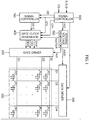
- FIG. 1 is a block diagram of an exemplary embodiment of a display device according to the present invention.
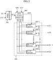
- FIG. 2 is a detailed block diagram of an exemplary embodiment of a portion of the display device according to the present invention.
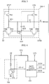
- FIG. 3 is a circuit diagram of an exemplary embodiment of a first stage according to the present invention.
- FIG. 4 is a circuit diagram of an exemplary embodiment of a signal converter according to the present invention.
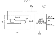
- FIG. 5 is a circuit diagram of another exemplary embodiment of a signal converter according to the present invention.
- FIG. 6 is a waveform diagram illustrating exemplary embodiments of an operation of the display device according to the present invention.
- the display device includes a display panel 100, a gate driver 200, a data driver 300, a gate clock generator 400, a driving voltage generator 500, a signal controller 600, and a signal converter 700.
- the display panel 100 includes a plurality of gate lines G1 to Gn which extend in one direction, and a plurality of data lines D1 to Dm which extend in a direction crossing the gate lines G1 to Gn.
- the display panel 100 includes a plurality of pixels PX connected to the gate lines G1 to Gn and the data lines D1 to Dm.
- the pixels PX are arranged in a matrix form within a display region of the display panel 100.
- Each of the pixels PX includes a thin film transistor ("TFT") T and a pixel capacitor Clc.
- each of the pixels PX further includes a storage capacitor Cst.
- the plurality of pixels display red (R), green (G) or blue (B), respectively.
- the display panel 100 includes a top substrate (not shown) and a bottom substrate (not shown).
- the bottom substrate includes TFTs T, gate lines. G1 to Gn, data lines D1 to Dm, pixel electrodes for pixel capacitors Clc and storage capacitors Cst, and storage electrodes for storage capacitors Cst.
- the top substrate includes a light blocking pattern (e.g., a black matrix), a color filter, and common electrodes for the pixel capacitors Clc.
- a liquid crystal layer (not shown) is interposed between the top substrate and the bottom substrate.
- Gate terminals of the TFTs T are connected to the gate lines G1 to Gn, source terminals are connected to the data line D1 to Dm, drain terminals are connected to the pixel electrodes.
- the TFTs T operate in response to gate turn-on signals applied to the gate lines G1 to Gn and supply data signals (i.e., gray-scale signals) of the data lines D1 to Dm to the pixel electrodes to change electric fields formed across the pixel capacitors Clc. Due to the change of the electric fields, the arrangement of liquid crystals within the display panel 100 is changed, and thus, the transmittance of light supplied from a backlight is controlled.
- the pixel electrodes include a plurality of cut-away and/or protrusion patterns as a domain regulator which regulates the alignment direction of the liquid crystals.
- the common electrodes may include a plurality of protrusion and/or cut-away patterns.
- the liquid crystals are vertically aligned.
- the present invention is not limited hereto, and may vary as necessary.
- control elements such as the gate driver 200, the data driver 300, the gate clock generator 400, the driving voltage generator 500, the signal controller 600, and the signal converter 700 are provided outside the display panel 100. These control elements supply driving control signals to the display panel 100, so that the display panel 100 receives external light and displays an image.
- the control elements are manufactured as IC chip and are electrically connected to the display panel 100. The respective control elements may be separately manufactured, or some of them may be integrated in a single chip. Some of the control elements may also be manufactured together with the display panel 100.
- the gate driver 200 is integrated into the bottom substrate of the display panel 100. That is, the gate driver 200 is manufactured together with the TFTs T of the display panel 100. The control elements will be described below in more detail.
- the signal controller 600 receives image signals R, G and B and an image control signal CS from an external graphic controller (not shown).
- the image signals R, G and B include primary pixel data, i.e., red, green, and blue color data.
- the image control signal CS includes a vertical sync signal ("Vsync”), a horizontal sync signal (“Hsync”), a main clock (“DCLK”), and a data enable signal (“DE”).
- the signal controller 600 processes the image signals R, G and B in accordance with operation conditions of the display panel 100.
- the signal controller 600 generates a plurality of control signals including a gate control signal and a data control signal. More specifically, the signal controller 600 transmits the gate control signal to the signal converter 700 and the gate clock generator 400, and transmits the data control signal to the data driver 300.
- the gate control signal includes a first output enable signal OE, a first vertical sync start signal STV, and a driving clock signal CPV.
- the data control signal (not shown) includes a horizontal sync start signal, a load signal, and a data clock signal.
- the horizontal sync start signal indicates the starting of transmission of the pixel data signal.
- the load signal instructs the application of a data voltage to a corresponding data line.
- the data control signal further includes an inversion signal which inverts the polarity of a gray-scale voltage with respect to a common voltage.
- the signal controller 600 is manufactured in an IC chip configuration and is mounted on a printed circuit board (“PCB”) (not shown) electrically connected to the display panel 100. Although not shown, the signal controller 600 is electrically connected to the gate driver 200 through a flexible printed circuit board (“FPCB”) (not shown) connected to the PCB (not shown).
- PCB printed circuit board
- FPCB flexible printed circuit board
- the driving voltage generator 500 generates a variety of driving voltages necessary for driving the display device using an external voltage VCC received from the signal controller 600.
- the driving voltage generator 500 generates a reference voltage AVDD, a gate turn-on voltage Von, a gate turn-off voltage Voff, and a common voltage.
- the driving voltage generator 500 applies the gate turn-on voltage Von and the gate turn-off voltage Voff to the gate clock generator 400 and applies the reference voltage AVDD to the data driver 300 according to the control signals of the signal controller 600.
- the reference voltage AVDD is used as a standard voltage to generate a gray-scale voltage for driving the liquid crystals.
- the data driver 300 generates the gray-scale signals by using the data control signal and the pixel data signal from the signal controller 600 and the reference voltage AVDD from the driving voltage generator 500, and applies the generated gray-scale signals to the respective data lines D1-Dm. That is, the data driver 300 is driven according to the data control signal and converts digital pixel data signals into analog gray-scale signals using the reference voltage AVDD. The data driver 300 supplies the converted gray-scale signals to the plurality of data lines D1 to Dm
- the signal converter 700 outputs a second output enable signal OE-C according to the first output enable signal OE and the first vertical sync start signal STV.
- the signal converter 700 changes the first output enable signal OE to a logic low level during a period in which the first vertical sync start signal STV is applied. That is, the second output enable signal OE-C is maintained at a logic low level during a logic high period of the first vertical sync start signal STV, and includes the same logic level as the first output enable signal OE during the remaining period.
- the first vertical sync start signal STV indicates the start of one frame and the first vertical sync start signal STV is a single pulse signal having one logic high period during one frame.
- the gate clock generator 400 generates a second vertical sync start signal STVP, a gate clock signal CKV, and a gate clock bar signal CKVB according to the second output enable signal OE-C, the first vertical sync start signal STV, the driving clock signal CPV, and the gate turn-on voltage Von and the gate turn-off voltage Voff of the driving voltage generator 500.
- the gate clock generator 400 supplies the second vertical sync start signal STVP, the gate clock signal CKV, and the gate clock bar signal CKVB to the gate driver 200.
- the gate clock signal CKV, the gate clock bar signal CKVB, and the second vertical sync start signal STVP have the voltage level of the gate turn-on voltage Von and the gate turn-off voltage Voff.
- the second vertical sync start signal STVP is generated by increasing the voltage level of the first vertical sync start signal STV up to the voltage level of the gate turn-on voltage Von. That is, the second vertical sync start signal STVP includes the same waveform as the first vertical sync start signal STV. However, the second vertical sync signal STVP includes the voltage level of the gate turn-on voltage Von during its logic high period.
- the gate driver 200 applies the gate turn-on signal Von and the gate turn-off signal Voff to the plurality of gate lines G1 to Gn according to the second vertical sync start signal STVP, the gate clock signal CKV, and the gate clock bar signal CKVB.
- the gate turn-on signal Von is sequentially supplied to the plurality of gate lines G1 to Gn.
- the gate turn-on signal Von is a single pulse signal during one frame period.
- the gate turn-on signal Von may be supplied to the gate lines G1 to Gn during one horizontal clock period (1H).
- the gate turn-on signal Von may be supplied to the gate lines G1 to Gn during a logic high period of the gate clock signal CKV or the gate clock bar signal CKVB. Therefore, the TFTs T connected to the respective gate lines G1 to Gn are turned on, and images are displayed.
- the signal converter 700 which converts the first output enable signal OE using the first vertical sync start signal STV is located between the signal controller 600 and the gate clock generator 400, it is possible to prevent the voltage level of the gate turn-on signal Von , which is applied to the first gate line G1, from being distorted (i.e., decreased) by a low ambient temperature. This will be described below in more detail.
- the gate driver 200 will be described with reference to FIG. 2 .
- the gate driver 200 includes first to n-th stages 200-1 to 200-n connected to the plurality of gate lines G1 to Gn, respectively.
- the first to n-th stages 200-1 to 200-n supply the gate turn-on signal Von or the gate turn-off signal Voff to the plurality of gate lines G1 to Gn according to the plurality of operation signals.
- the operation signals include the gate clock signal CKV, the gate clock bar signal CKVB, and the second vertical sync start signal STVP or output signals of the previous stages 200-1 to 200-n-1.
- the first stage 200-1 is driven by the second vertical sync start signal STVP, the gate clock signal CKV, the gate clock bar signal CKVB, and the gate turn-off signal Voff, and applies the first gate turn-on signal Von to the first gate line G1.
- the second to n-th stages 200-2 to 200-n are driven by the output signals (i.e., the gate turn-on signals Von) of the previous stages 200-1 to 200-n-1, the gate clock signal CKV and the gate clock bar signal CKVB, and apply the gate turn-on signals Von to the second to n-th gate lines G2 to Gn, respectively.
- the first to (n-1)-th stages 200-1 to 200-n-1 are reset by the output signals (i.e., the gate turn-on signals Von) of their next stages, i.e., the second to n-th stages 200-2 to 200-n.
- the last stage, i.e., the n-th stage 200-n may also be reset by an output signal of a dummy stage (not shown) disposed under the n-th stage 200-n.
- the n-th stage 200-n may also be reset by a separate control signal.
- each of the first to n-th stages 200-1 to 200-n may include seven TFTs.
- the first stage 200-1 includes a first transistor TR1, a second transistor TR2, a third transistor TR3, a fourth transistor TR4, a fifth transistor TR5, a sixth transistor TR6, a seventh transistor TR7, a first capacitor C1 and a second capacitor C2.
- the first transistor TR1 provides the gate clock signal CKV of a gate clock signal input terminal to a signal output terminal in response to the signal of the first node NO1.
- the second transistor TR2 provides the second vertical sync start signal STVP to a first node NO1 in response to the second vertical sync start signal STVP.
- the third transistor TR3 provides the signal of the first node NO1 to the ground voltage VSS in response to an output signal of the second stage 200-2.
- the fourth transistor TR4 provides the signal of the first node NO1 to the ground voltage VSS in response to a signal of a second node NO2.
- the fifth transistor TR5 provides a signal from the signal output terminal to the ground voltage VSS in response to the signal of the second node NO2.
- the sixth transistor TR6 provides a signal of the signal output terminal to the ground voltage VSS in response to the gate clock bar signal CKVB.
- the seventh transistor TR7 provides the signal of the second node NO2 to the ground voltage VSS in response to the signal of the first node NO1.
- the first capacitor C1 is connected between the first node NO1 and the signal output terminal.
- the second capacitor C2 is connected between the second node NO2 and the input terminal of the gate clock signal CKV.
- the input terminal of the gate clock signal CKV and the input terminal of the gate clock bar signal CKVB may be exchanged with each other.
- the second to n-th stages 200-2 to 200-n receive the output signals of the previous stages, i.e., the first to (n-1)-th stages 200-1 to 200-n-1, instead of the second vertical sync start signal STVP.
- a simplified circuit configuration of the stage is illustrated in FIG.
- the voltage levels of the second vertical sync start signal STVP, the gate clock signal CKV, and the gate clock bar signal CKVB are similar or equal to the voltage level of the gate turn-on signal Von.
- the second vertical sync start signal STVP is supplied to the first stage 200-1.
- the second vertical sync start signal STVP is applied to the first node NO1 through the second transistor TR2.
- the first transistor TR1 is turned on in response to the second vertical sync start signal STVP applied to the first node NO1.
- the first capacitor C1 is charged to a voltage corresponding to the voltage level of the second vertical sync start signal STVP as indicated by "A" in FIG. 6 .
- the charging time of the first capacitor C1 in the first stage 200-1 can be sufficiently ensured by the gate clock signal CKV generated using the second output enable signal OE-C outputted from the signal converter 700. As illustrated in FIG.
- the period T1 can be used as the charging time of the first capacitor C1.
- a period corresponding to approximately 50% of 1 horizontal clock period 1H is used as the charging time of the first capacitor C1.
- the gate clock signal CKV of a logic high level is supplied to the first stage 200-1.
- the gate clock signal CKV is applied to the signal output terminal through the turned-on first transistor TR1.
- the gate clock signal CKV of the logic high level is applied to the signal output terminal, the voltage level of the first node NO1 increases due to the coupling of the first capacitor C1.
- the first transistor TR1 is fully turned on. Therefore, the gate clock signal CKV can be provided to the signal output terminal without voltage drop.
- the gate clock signal CKV on the signal output terminal is applied as the gate turn-on signal to the first gate line G1.
- FIG. 6 is a waveform diagram of the signals used in the display device on the assumption that no delay occurs in the signals. According to an exemplary embodiment, the signals of FIG. 6 may be inclined during the level transition due to the signal delay.
- the voltage of the first node NO1 increases up to the voltage level of the second vertical sync start signal STVP at an early stage and its voltage level increases by the first capacitor C1 when the gate clock signal CKV is inputted.
- the gate clock signal CKV is applied before the first capacitor C1 is sufficiently charged, so that the voltage level of the first node NO1 does not sufficiently increase. Because the first transistor TR1 is not fully turned on, the voltage level of the gate turn-on signal is decreased. In the exemplary embodiment, however, the gate clock signal CKV is applied after a predetermined time (T1 in FIG.
- the logic high period of the gate clock signal CKV applied to the first stage 200-1 is reduced so as to provide a sufficient charging time to the first capacitor C1 of the first stage 200-1. This means the variation of the pulse width of the gate turn-on signal applied to the first gate line G1.
- the second output enable signal OE-C is generated using the first output enable signal OE and the first vertical sync start signal STV, and it is applied to the gate clock generator 400 so as to generate gate clock signal CKV. That is, the logic high period of the gate clock signal CKV applied to the firs stage 200-1 is reduced because the signal converter 700 provides the second output enable signal OE-C to the gate clock generator 400.
- the gate clock generator 400 generates the gate clock signal CKV and the gate clock bar signal CKVB by using the logic 'OR' operation of the second output enable signal OE-C and the driving clock signal CPV.
- the logic 'OR' operation output a logic high level when the second output enable signal OE-C or the driving clock signal CPV is a logic high level. And the logic 'OR' operation output a logic low level when the second output enable signal OE-C and the driving clock signal CPV are logic low levels.
- the voltage levels of the gate clock signal CKV and the gate clock bar signal CKVB are the gate turn-on voltage Von and the gate turn-off voltage Voff.
- the gate clock generator 400 generates the second vertical sync start signal STVP by using the first vertical sync start signal STV, the gate turn-on voltage Von, and the gate turn-off voltage Voff.As illustrated in FIG.
- the gate clock generator 400 during the first 1H period of one frame, the gate clock generator 400 generates the gate clock signal CKV of a logic high level when the second output enable signal OE-C or the driving clock signal CPV is a logic high level.
- the gate clock generator 400 inverts the logic levels of the gate clock signal CKV and the gate clock bar signal CKVB when the logic OR operation of the second output enable signal OE-C and the driving clock signal CPV is zero. That is, when the second output enable signal OE-C of a logic low level or the driving clock signal CPV of a logic low level switches to a logic high level, the gate clock generator 400 inverts the logic level of the gate clock signal CKV.
- the gate clock signal CKV of the logic high level becomes the gate turn-on signal Von, and the voltage of the logic low level becomes the gate turn-off signal Voff. Further, as indicated by "T1" in FIG. 6 , the gate clock signal CKV is not applied as the output signal when both the second output enable signal OE-C and the driving clock signal CPV are at the logic low level during the logic high period of the second vertical sync start signal STVP. During this logic high period of the second vertical sync start signal STVP, the first capacitors C1 of the stages 200-1 to 200-n are charged up by the external signal.
- the generation of the first gate clock signal CKV applied to the first stage 200-1 will be described below.
- the driving clock signal CPV changes from the logic low level to the logic high level. Therefore, the first gate clock signal CKV has a logic low level when both the second output enable signal OE-C and the driving clock signal CPV are in the logic low level, but has a logic high level when the driving clock signal CPV changes to the logic high level.
- the first capacitor C1 of the first stage 200-1 can be sufficiently charged to the voltage level of the second vertical sync start signal STVP because both the second output enable signal OE-C and the driving clock signal CPV maintain the logic low level for a long period. Then, the second output enable signal OE-C changes from the logic low level to the logic high level and again changes to the logic low level. The driving clock signal CPV changes from the logic low level to the logic high level. At this point, the second output enable signal OE-C maintains the logic low level for a short period and then changes to the logic high level. Therefore, the period in which both the second output enable signal OE-C and the driving clock signal CPV maintain the logic low level is shortened.
- the gate clock bar signal CKVB has a phase opposite to that of the remaining gate clock signals CKV except the first gate clock signal CKV within one frame. That is, the gate clock bar signal CKVB maintains the logic low level during the first horizontal clock period 1H, and it has a phase opposite to that of the gate clock signal CKV during the following horizontal clock periods.
- the second output enable signal OE-C supplied to the gate clock generator 400 so as to generate the gate clock signal CKV is generated in the signal converter 700 using the first output enable signal OE and the first vertical sync start signal STV. That is, the first stage is operated by the first vertical sync start signal STV to supply the gate turn-on signal to the first gate line G1. Therefore, during the logic high period of the first vertical sync start signal STV, the second output enable signal OE-C is generated by forcibly changing the first output enable signal OE to the logic low level. In this way, the period in which both the second output enable signal OE-C and the driving clock signal CPV are at the logic low level can be sufficiently long. Consequently, the time when the first capacitor C1 of the first stage is charged to the second vertical sync time signal STVP is lengthened.
- the signal converter 700 includes an input/output node I/O and a switching unit 710.
- the signal converter 700 converts the first output enable signal OE to output the second output enable signal OE-C.
- the switching unit 710 electrically connects the input/output node I/O to the ground in response to the first vertical sync start signal STV.
- the switching unit 710 may be implemented with a transistor. That is, the signal converter 700 outputs the first output enable signal OE as the second output enable signal OE-C when the first vertical sync start signal STV is logic low level (i.e.
- the second output enable signal OE-C includes the logic low level, regardless of the logic level of the first output enable signal OE.
- the signal converter 700 having the switching unit 710 is connected to an input pin of the gate clock generator 400 to convert the first output enable signal OE of the signal controller 600, so that the second output enable signal OE-C can be provided to the gate clock generator 400.
- the width of the logic high period of the gate clock signal CKV is changed using the second output enable signal OE-C.
- the voltage drop of the gate turn-on signal Von at a low temperature is prevented, thereby the low-temperature driving ability can be improved.
- the signal converter 700 is not limited to the above-mentioned configuration, but can be implemented with a variety of circuit configurations. As illustrated in FIG. 5 , the signal converter 700 includes a first logic gate to perform a NAND operation on the first vertical sync start signal STV and the first output enable signal OE, and a second logic gate to perform an AND operation on an output of the first logic gate and the first output enable signal OE.
- the first logic gate is implemented with a NAND gate "NAND”
- the second logic gate is implemented with an AND gate "AND”. That is, the NAND gate "NAND" outputs the logic low signal when both the first output enable signal OE and the first vertical sync start signal STV have the logic high level.
- the AND gate “AND” When the output of the NAND gate “NAND” is the logic low level, the AND gate “AND” outputs the second output enable signal OE-C of the logic low level, regardless of the logic level of the first output enable signal OE.
- the signal converter 700 the logic high period of the first output enable signal OE can be eliminated within the logic high period of the first vertical sync start signal STV.
- the signal controller 600 generates the gate control signals and the data control signals according to the external control signal inputted from the external controller.
- the gate control signals include the first output enable signal OE, the driving control signal CPV, and the first vertical sync start signal STV.
- the data control signals include the pixel data signal.
- the signal controller 600 outputs the first output enable signal OE and the driving clock signal CPV.
- the signal controller 600 outputs the first vertical sync start signal STV at each start of one frame.
- the signal converter 700 forcibly changes the first output enable signal OE to the logic low level during the logic high period of the first vertical sync start signal STV, and outputs the second output enable signal OE-C to the gate clock generator 400.
- the second output enable signal OE-C maintains the logic low level during the logic high period of the first vertical sync start signal STV and includes the same logic level as the first output enable signal OE during the remaining periods.
- the gate clock generator 400 generates the gate clock signal CKV and the gate clock bar signal CKVB according to the second output enable signal OE-C and the driving clock signal CPV.
- the gate clock generator 400 generates the second vertical sync start signal STVP according to the first vertical sync start signal STV. Amplitudes of the gate clock signal CKV, the gate clock bar signal CKVB, and the second vertical sync start signal STVP have the same voltage level as the gate turn-on voltage Von.
- the width of the logic high periods of the gate clock signal CKV and the gate clock bar signal CKVB is equal to the sum of the logic high periods of the second output enable signal OE-C and the driving clock signal CPV.
- the width of the logic high period of the second vertical sync start signal STVP is equal to that of the first vertical sync start signal STV. Therefore, the second output enable signal OE-C includes the logic low level during the period in which the first vertical sync start signal STV is applied.
- the gate clock generator 400 generates the gate clock signal CKV of the logic high level only when the driving clock signal CPV is at the logic high level. That is, during the period in which the first vertical sync start signal STV is applied, the gate clock signal CKV maintains the logic high level during the latter half of the first horizontal clock period 1H, not during the entire horizontal clock period 1H.
- the gate driver 200 supplies the gate turn-on signals Von to the gate lines G1 to Gn according to the second vertical sync start signal STVP, the gate clock signal CKV, and the gate clock bar signal CKVB.
- the gate driver 200 includes the plurality of stages 200-1 to 200-n connected to the gate lines G1 to Gn to apply the gate turn-on signals Von to the corresponding gate lines G1 to Gn using the inputted signals.
- the width of the logic high period of the gate clock signal CKV is reduced during the period in which the first vertical sync start signal STV, that is, the second vertical sync start signal STVP is applied.
- the first stage 200-1 connected to the first gate line G1 is driven by the second vertical sync start signal STVP.
- the gate clock signal CKV is applied to the first stage 200-1 after a predetermined time (e.g., about H/2) elapses from the application of the second vertical sync start signal STVP. Therefore, the gate turn-on signal Von having the period width smaller than the one horizontal clock period 1H is applied to the first gate line G1.
- the first capacitor C1 of the first stage 200-1 can be sufficiently charged to the voltage level of the second vertical sync start signal STVP because the gate clock signal CKV is applied after a predetermined time elapses from the application of the second vertical sync start signal STVP.
- the gate turn-on signal Von having the normal voltage level is applied to the first gate line G1 without voltage drop.
- the width of the logic high period of the gate clock signal CKV applied to the first gate line is adjusted using the signal converter 700 which converts the logic level of the first output enable signal OE according to the first vertical sync start signal STV. Therefore, when the gate driver 200 is integrated into the display panel 100 in the stage form, it is possible to prevent the voltage level of the gate turn-on signal Von applied to the first gate line G1 from being distorted by the reduced drivability of the stage according to the ambient temperature.
- the lowering of the voltage level of a gate turn-on signal Von applied to a first gate line at a low temperature can be prevented by changing the logic level of the output enable signal according to the vertical sync start signal.
- the logic level of the output enable signal is changed using switches or logic circuits, so that increase of the manufacturing cost can be minimized and the driving ability at a low temperature can be improved.
- the signal converter 700 is provided in a separate chip or circuit configuration so that it is separated from the signal controller 600 and the gate clock generator 400.
- the present invention is not limited to this configuration.
- a separate module serving as the signal converter 700 can be provided in the signal controller 600 or the gate clock generator 400.
Landscapes
- Engineering & Computer Science (AREA)
- Physics & Mathematics (AREA)
- General Physics & Mathematics (AREA)
- Chemical & Material Sciences (AREA)
- Crystallography & Structural Chemistry (AREA)
- Theoretical Computer Science (AREA)
- Computer Hardware Design (AREA)
- Nonlinear Science (AREA)
- Microelectronics & Electronic Packaging (AREA)
- Optics & Photonics (AREA)
- Mathematical Physics (AREA)
- Power Engineering (AREA)
- Control Of Indicators Other Than Cathode Ray Tubes (AREA)
- Liquid Crystal Display Device Control (AREA)
- Liquid Crystal (AREA)
- Shift Register Type Memory (AREA)
Applications Claiming Priority (1)
| Application Number | Priority Date | Filing Date | Title |
|---|---|---|---|
| KR1020070073000A KR101432717B1 (ko) | 2007-07-20 | 2007-07-20 | 표시 장치 및 이의 구동 방법 |
Publications (3)
| Publication Number | Publication Date |
|---|---|
| EP2017818A2 EP2017818A2 (en) | 2009-01-21 |
| EP2017818A3 EP2017818A3 (en) | 2009-08-26 |
| EP2017818B1 true EP2017818B1 (en) | 2017-04-05 |
Family
ID=39868556
Family Applications (1)
| Application Number | Title | Priority Date | Filing Date |
|---|---|---|---|
| EP08012743.4A Active EP2017818B1 (en) | 2007-07-20 | 2008-07-15 | Display device and method for driving the same |
Country Status (6)
| Country | Link |
|---|---|
| US (1) | US20090021502A1 (zh) |
| EP (1) | EP2017818B1 (zh) |
| JP (1) | JP5514407B2 (zh) |
| KR (1) | KR101432717B1 (zh) |
| CN (1) | CN101350167B (zh) |
| TW (1) | TWI451391B (zh) |
Families Citing this family (15)
| Publication number | Priority date | Publication date | Assignee | Title |
|---|---|---|---|---|
| JP2009271531A (ja) | 2008-04-30 | 2009-11-19 | Samsung Corning Precision Glass Co Ltd | ディスプレイフィルター及びそれを具備するディスプレイ装置 |
| KR101478667B1 (ko) * | 2008-10-16 | 2015-01-02 | 삼성디스플레이 주식회사 | 표시 장치 및 이의 구동 방법 |
| TWI406222B (zh) * | 2009-05-26 | 2013-08-21 | Chunghwa Picture Tubes Ltd | 具有輸出致能控制電路之閘極驅動器 |
| CN102024431B (zh) | 2009-09-16 | 2013-04-03 | 北京京东方光电科技有限公司 | Tft-lcd驱动电路 |
| TWI417861B (zh) * | 2009-11-12 | 2013-12-01 | Himax Tech Ltd | 閘極驅動器與其驅動方法 |
| WO2012077620A1 (ja) * | 2010-12-10 | 2012-06-14 | シャープ株式会社 | 表示装置のタイミング制御回路、表示装置、および表示装置のタイミング制御方法 |
| CN202008813U (zh) * | 2010-12-23 | 2011-10-12 | 北京京东方光电科技有限公司 | 薄膜晶体管液晶显示器的栅极驱动器、驱动电路及液晶显示器 |
| CN102855838B (zh) * | 2011-06-30 | 2015-07-08 | 上海天马微电子有限公司 | 用于显示器的时序控制器 |
| US9030399B2 (en) * | 2012-02-23 | 2015-05-12 | Au Optronics Corporation | Gate driver stage outputting multiple, partially overlapping gate-line signals to a liquid crystal display |
| KR102114155B1 (ko) * | 2013-10-01 | 2020-05-25 | 삼성디스플레이 주식회사 | 표시 장치 및 그 구동 방법 |
| KR102314071B1 (ko) | 2014-12-26 | 2021-10-19 | 삼성디스플레이 주식회사 | 게이트 구동부 및 그것을 포함하는 표시 장치 |
| KR102549431B1 (ko) * | 2015-11-27 | 2023-06-30 | 삼성디스플레이 주식회사 | 표시 장치 |
| CN107331339B (zh) * | 2016-04-29 | 2020-10-27 | 上海和辉光电股份有限公司 | 显示装置及其控制方法 |
| KR102439583B1 (ko) * | 2018-04-30 | 2022-09-05 | 에스케이하이닉스 주식회사 | 메모리 장치 및 그의 신호 전송 회로 |
| KR102649600B1 (ko) * | 2020-01-17 | 2024-03-22 | 삼성디스플레이 주식회사 | 클럭 생성기 및 이를 포함하는 표시 장치 |
Family Cites Families (14)
| Publication number | Priority date | Publication date | Assignee | Title |
|---|---|---|---|---|
| TW552573B (en) * | 2001-08-21 | 2003-09-11 | Samsung Electronics Co Ltd | Liquid crystal display and driving method thereof |
| KR100796298B1 (ko) * | 2002-08-30 | 2008-01-21 | 삼성전자주식회사 | 액정표시장치 |
| KR20040029724A (ko) * | 2002-10-02 | 2004-04-08 | 삼성전자주식회사 | 액정 표시 장치 |
| KR100945581B1 (ko) * | 2003-06-23 | 2010-03-08 | 삼성전자주식회사 | 액정 표시 장치 및 그 구동 방법 |
| KR100951901B1 (ko) * | 2003-08-14 | 2010-04-09 | 삼성전자주식회사 | 신호 변환 장치 및 이를 갖는 표시 장치 |
| US6870401B1 (en) * | 2003-08-29 | 2005-03-22 | Matsushita Electric Industrial Co., Ltd. | Signal transmission circuit |
| JP3958306B2 (ja) * | 2003-09-02 | 2007-08-15 | シャープ株式会社 | 液晶表示装置 |
| KR100995637B1 (ko) * | 2003-12-29 | 2010-11-19 | 엘지디스플레이 주식회사 | 쉬프트 레지스터 |
| JP2005285168A (ja) * | 2004-03-29 | 2005-10-13 | Alps Electric Co Ltd | シフトレジスタ及びそれを用いた液晶駆動回路 |
| KR20060089829A (ko) * | 2005-02-04 | 2006-08-09 | 삼성전자주식회사 | 표시 장치 및 그 구동 방법 |
| US7586476B2 (en) * | 2005-06-15 | 2009-09-08 | Lg. Display Co., Ltd. | Apparatus and method for driving liquid crystal display device |
| JP4822406B2 (ja) * | 2005-09-26 | 2011-11-24 | ルネサスエレクトロニクス株式会社 | 表示制御駆動装置および表示システム |
| JP4777050B2 (ja) * | 2005-11-21 | 2011-09-21 | 東芝モバイルディスプレイ株式会社 | 表示パネル制御回路 |
| TWI319556B (en) * | 2005-12-23 | 2010-01-11 | Chi Mei Optoelectronics Corp | Compensation circuit and method for compensate distortion of data signals of liquid crystal display device |
-
2007
- 2007-07-20 KR KR1020070073000A patent/KR101432717B1/ko active IP Right Grant
-
2008
- 2008-06-06 JP JP2008149201A patent/JP5514407B2/ja active Active
- 2008-06-26 US US12/147,131 patent/US20090021502A1/en not_active Abandoned
- 2008-07-15 EP EP08012743.4A patent/EP2017818B1/en active Active
- 2008-07-18 TW TW097127388A patent/TWI451391B/zh active
- 2008-07-21 CN CN2008102147486A patent/CN101350167B/zh active Active
Non-Patent Citations (1)
| Title |
|---|
| None * |
Also Published As
| Publication number | Publication date |
|---|---|
| KR20090009586A (ko) | 2009-01-23 |
| EP2017818A3 (en) | 2009-08-26 |
| KR101432717B1 (ko) | 2014-08-21 |
| EP2017818A2 (en) | 2009-01-21 |
| TW200915289A (en) | 2009-04-01 |
| US20090021502A1 (en) | 2009-01-22 |
| JP2009025804A (ja) | 2009-02-05 |
| CN101350167B (zh) | 2012-09-05 |
| TWI451391B (zh) | 2014-09-01 |
| CN101350167A (zh) | 2009-01-21 |
| JP5514407B2 (ja) | 2014-06-04 |
Similar Documents
| Publication | Publication Date | Title |
|---|---|---|
| EP2017818B1 (en) | Display device and method for driving the same | |
| US8154500B2 (en) | Gate driver and method of driving display apparatus having the same | |
| US8144114B2 (en) | Liquid crystal display | |
| JP4942405B2 (ja) | 表示装置用シフトレジスタ及びこれを含む表示装置 | |
| US8400390B2 (en) | Gate driving device and liquid crystal display having the same | |
| US20070052658A1 (en) | Driver for display apparatus and display apparatus including the same | |
| US8044908B2 (en) | Liquid crystal display device and method of driving the same | |
| US8749469B2 (en) | Display device for reducing parasitic capacitance with a dummy scan line | |
| US20130063331A1 (en) | Gate driving circuit having improved tolerance to gate voltage ripple and display device having the same | |
| US8542227B2 (en) | Display apparatus and method for driving the same | |
| US20080303809A1 (en) | Display and method of driving the same | |
| US8736596B2 (en) | Liquid crystal display panel and display device having the display panel | |
| US20070018940A1 (en) | Display device using enhanced gate driver | |
| US20130069930A1 (en) | Shift register, scanning signal line drive circuit, and display device | |
| EP1811488A2 (en) | Driving device, display device, and method of driving the same | |
| US20120120044A1 (en) | Liquid crystal display device and method for driving the same | |
| TW200405235A (en) | Shift register and liquid crystal display having the same | |
| US20090066684A1 (en) | Display and discharging device of the same | |
| US8913046B2 (en) | Liquid crystal display and driving method thereof | |
| US8009155B2 (en) | Output buffer of a source driver applied in a display | |
| US20080084378A1 (en) | Display device and method for driving the same | |
| US7830354B2 (en) | Driving apparatus for display device that uses control signals based on sum of clock signals | |
| KR101654323B1 (ko) | 액정표시장치 및 그의 보상 방법 | |
| US10304406B2 (en) | Display apparatus with reduced flash noise, and a method of driving the display apparatus | |
| US8040314B2 (en) | Driving apparatus for liquid crystal display |
Legal Events
| Date | Code | Title | Description |
|---|---|---|---|
| PUAI | Public reference made under article 153(3) epc to a published international application that has entered the european phase |
Free format text: ORIGINAL CODE: 0009012 |
|
| AK | Designated contracting states |
Kind code of ref document: A2 Designated state(s): AT BE BG CH CY CZ DE DK EE ES FI FR GB GR HR HU IE IS IT LI LT LU LV MC MT NL NO PL PT RO SE SI SK TR |
|
| AX | Request for extension of the european patent |
Extension state: AL BA MK RS |
|
| PUAL | Search report despatched |
Free format text: ORIGINAL CODE: 0009013 |
|
| AK | Designated contracting states |
Kind code of ref document: A3 Designated state(s): AT BE BG CH CY CZ DE DK EE ES FI FR GB GR HR HU IE IS IT LI LT LU LV MC MT NL NO PL PT RO SE SI SK TR |
|
| AX | Request for extension of the european patent |
Extension state: AL BA MK RS |
|
| 17P | Request for examination filed |
Effective date: 20100223 |
|
| AKX | Designation fees paid |
Designated state(s): DE FR GB |
|
| 17Q | First examination report despatched |
Effective date: 20100422 |
|
| RAP1 | Party data changed (applicant data changed or rights of an application transferred) |
Owner name: SAMSUNG ELECTRONICS CO., LTD. |
|
| RAP1 | Party data changed (applicant data changed or rights of an application transferred) |
Owner name: SAMSUNG DISPLAY CO., LTD. |
|
| RAP1 | Party data changed (applicant data changed or rights of an application transferred) |
Owner name: SAMSUNG DISPLAY CO., LTD. |
|
| REG | Reference to a national code |
Ref country code: DE Ref legal event code: R079 Ref document number: 602008049551 Country of ref document: DE Free format text: PREVIOUS MAIN CLASS: G09G0003360000 Ipc: G11C0019180000 |
|
| RIC1 | Information provided on ipc code assigned before grant |
Ipc: G11C 19/18 20060101AFI20160531BHEP Ipc: G09G 3/36 20060101ALI20160531BHEP |
|
| GRAP | Despatch of communication of intention to grant a patent |
Free format text: ORIGINAL CODE: EPIDOSNIGR1 |
|
| INTG | Intention to grant announced |
Effective date: 20161206 |
|
| GRAS | Grant fee paid |
Free format text: ORIGINAL CODE: EPIDOSNIGR3 |
|
| GRAA | (expected) grant |
Free format text: ORIGINAL CODE: 0009210 |
|
| AK | Designated contracting states |
Kind code of ref document: B1 Designated state(s): DE FR GB |
|
| REG | Reference to a national code |
Ref country code: GB Ref legal event code: FG4D |
|
| REG | Reference to a national code |
Ref country code: DE Ref legal event code: R096 Ref document number: 602008049551 Country of ref document: DE |
|
| REG | Reference to a national code |
Ref country code: FR Ref legal event code: PLFP Year of fee payment: 10 |
|
| REG | Reference to a national code |
Ref country code: DE Ref legal event code: R097 Ref document number: 602008049551 Country of ref document: DE |
|
| PLBE | No opposition filed within time limit |
Free format text: ORIGINAL CODE: 0009261 |
|
| STAA | Information on the status of an ep patent application or granted ep patent |
Free format text: STATUS: NO OPPOSITION FILED WITHIN TIME LIMIT |
|
| 26N | No opposition filed |
Effective date: 20180108 |
|
| REG | Reference to a national code |
Ref country code: FR Ref legal event code: PLFP Year of fee payment: 11 |
|
| P01 | Opt-out of the competence of the unified patent court (upc) registered |
Effective date: 20230515 |
|
| PGFP | Annual fee paid to national office [announced via postgrant information from national office to epo] |
Ref country code: GB Payment date: 20240620 Year of fee payment: 17 |
|
| PGFP | Annual fee paid to national office [announced via postgrant information from national office to epo] |
Ref country code: FR Payment date: 20240624 Year of fee payment: 17 |
|
| PGFP | Annual fee paid to national office [announced via postgrant information from national office to epo] |
Ref country code: DE Payment date: 20240620 Year of fee payment: 17 |