EP2017795B1 - Electromechanical lock - Google Patents
Electromechanical lock Download PDFInfo
- Publication number
- EP2017795B1 EP2017795B1 EP20070112676 EP07112676A EP2017795B1 EP 2017795 B1 EP2017795 B1 EP 2017795B1 EP 20070112676 EP20070112676 EP 20070112676 EP 07112676 A EP07112676 A EP 07112676A EP 2017795 B1 EP2017795 B1 EP 2017795B1
- Authority
- EP
- European Patent Office
- Prior art keywords
- key
- lock
- follower
- actuator
- during
- Prior art date
- Legal status (The legal status is an assumption and is not a legal conclusion. Google has not performed a legal analysis and makes no representation as to the accuracy of the status listed.)
- Active
Links
Images


Classifications
-
- G—PHYSICS
- G07—CHECKING-DEVICES
- G07C—TIME OR ATTENDANCE REGISTERS; REGISTERING OR INDICATING THE WORKING OF MACHINES; GENERATING RANDOM NUMBERS; VOTING OR LOTTERY APPARATUS; ARRANGEMENTS, SYSTEMS OR APPARATUS FOR CHECKING NOT PROVIDED FOR ELSEWHERE
- G07C9/00—Individual registration on entry or exit
- G07C9/00174—Electronically operated locks; Circuits therefor; Nonmechanical keys therefor, e.g. passive or active electrical keys or other data carriers without mechanical keys
- G07C9/00309—Electronically operated locks; Circuits therefor; Nonmechanical keys therefor, e.g. passive or active electrical keys or other data carriers without mechanical keys operated with bidirectional data transmission between data carrier and locks
-
- E—FIXED CONSTRUCTIONS
- E05—LOCKS; KEYS; WINDOW OR DOOR FITTINGS; SAFES
- E05B—LOCKS; ACCESSORIES THEREFOR; HANDCUFFS
- E05B47/00—Operating or controlling locks or other fastening devices by electric or magnetic means
- E05B47/0001—Operating or controlling locks or other fastening devices by electric or magnetic means with electric actuators; Constructional features thereof
- E05B2047/0014—Constructional features of actuators or power transmissions therefor
- E05B2047/0018—Details of actuator transmissions
- E05B2047/0026—Clutches, couplings or braking arrangements
-
- E—FIXED CONSTRUCTIONS
- E05—LOCKS; KEYS; WINDOW OR DOOR FITTINGS; SAFES
- E05B—LOCKS; ACCESSORIES THEREFOR; HANDCUFFS
- E05B47/00—Operating or controlling locks or other fastening devices by electric or magnetic means
- E05B2047/0048—Circuits, feeding, monitoring
- E05B2047/0057—Feeding
- E05B2047/0062—Feeding by generator
-
- E—FIXED CONSTRUCTIONS
- E05—LOCKS; KEYS; WINDOW OR DOOR FITTINGS; SAFES
- E05B—LOCKS; ACCESSORIES THEREFOR; HANDCUFFS
- E05B47/00—Operating or controlling locks or other fastening devices by electric or magnetic means
- E05B47/0001—Operating or controlling locks or other fastening devices by electric or magnetic means with electric actuators; Constructional features thereof
- E05B47/0012—Operating or controlling locks or other fastening devices by electric or magnetic means with electric actuators; Constructional features thereof with rotary electromotors
-
- G—PHYSICS
- G07—CHECKING-DEVICES
- G07C—TIME OR ATTENDANCE REGISTERS; REGISTERING OR INDICATING THE WORKING OF MACHINES; GENERATING RANDOM NUMBERS; VOTING OR LOTTERY APPARATUS; ARRANGEMENTS, SYSTEMS OR APPARATUS FOR CHECKING NOT PROVIDED FOR ELSEWHERE
- G07C9/00—Individual registration on entry or exit
- G07C9/00174—Electronically operated locks; Circuits therefor; Nonmechanical keys therefor, e.g. passive or active electrical keys or other data carriers without mechanical keys
- G07C2009/00634—Power supply for the lock
-
- G—PHYSICS
- G07—CHECKING-DEVICES
- G07C—TIME OR ATTENDANCE REGISTERS; REGISTERING OR INDICATING THE WORKING OF MACHINES; GENERATING RANDOM NUMBERS; VOTING OR LOTTERY APPARATUS; ARRANGEMENTS, SYSTEMS OR APPARATUS FOR CHECKING NOT PROVIDED FOR ELSEWHERE
- G07C9/00—Individual registration on entry or exit
- G07C9/00174—Electronically operated locks; Circuits therefor; Nonmechanical keys therefor, e.g. passive or active electrical keys or other data carriers without mechanical keys
- G07C2009/00753—Electronically operated locks; Circuits therefor; Nonmechanical keys therefor, e.g. passive or active electrical keys or other data carriers without mechanical keys operated by active electrical keys
- G07C2009/00769—Electronically operated locks; Circuits therefor; Nonmechanical keys therefor, e.g. passive or active electrical keys or other data carriers without mechanical keys operated by active electrical keys with data transmission performed by wireless means
-
- G—PHYSICS
- G07—CHECKING-DEVICES
- G07C—TIME OR ATTENDANCE REGISTERS; REGISTERING OR INDICATING THE WORKING OF MACHINES; GENERATING RANDOM NUMBERS; VOTING OR LOTTERY APPARATUS; ARRANGEMENTS, SYSTEMS OR APPARATUS FOR CHECKING NOT PROVIDED FOR ELSEWHERE
- G07C9/00—Individual registration on entry or exit
- G07C9/00174—Electronically operated locks; Circuits therefor; Nonmechanical keys therefor, e.g. passive or active electrical keys or other data carriers without mechanical keys
- G07C2009/00968—Electronically operated locks; Circuits therefor; Nonmechanical keys therefor, e.g. passive or active electrical keys or other data carriers without mechanical keys shape of the data carrier
- G07C2009/00992—Electronically operated locks; Circuits therefor; Nonmechanical keys therefor, e.g. passive or active electrical keys or other data carriers without mechanical keys shape of the data carrier mechanical key
-
- Y—GENERAL TAGGING OF NEW TECHNOLOGICAL DEVELOPMENTS; GENERAL TAGGING OF CROSS-SECTIONAL TECHNOLOGIES SPANNING OVER SEVERAL SECTIONS OF THE IPC; TECHNICAL SUBJECTS COVERED BY FORMER USPC CROSS-REFERENCE ART COLLECTIONS [XRACs] AND DIGESTS
- Y10—TECHNICAL SUBJECTS COVERED BY FORMER USPC
- Y10T—TECHNICAL SUBJECTS COVERED BY FORMER US CLASSIFICATION
- Y10T70/00—Locks
- Y10T70/50—Special application
- Y10T70/5889—For automotive vehicles
- Y10T70/5956—Steering mechanism with switch
-
- Y—GENERAL TAGGING OF NEW TECHNOLOGICAL DEVELOPMENTS; GENERAL TAGGING OF CROSS-SECTIONAL TECHNOLOGIES SPANNING OVER SEVERAL SECTIONS OF THE IPC; TECHNICAL SUBJECTS COVERED BY FORMER USPC CROSS-REFERENCE ART COLLECTIONS [XRACs] AND DIGESTS
- Y10—TECHNICAL SUBJECTS COVERED BY FORMER USPC
- Y10T—TECHNICAL SUBJECTS COVERED BY FORMER US CLASSIFICATION
- Y10T70/00—Locks
- Y10T70/60—Systems
- Y10T70/625—Operation and control
-
- Y—GENERAL TAGGING OF NEW TECHNOLOGICAL DEVELOPMENTS; GENERAL TAGGING OF CROSS-SECTIONAL TECHNOLOGIES SPANNING OVER SEVERAL SECTIONS OF THE IPC; TECHNICAL SUBJECTS COVERED BY FORMER USPC CROSS-REFERENCE ART COLLECTIONS [XRACs] AND DIGESTS
- Y10—TECHNICAL SUBJECTS COVERED BY FORMER USPC
- Y10T—TECHNICAL SUBJECTS COVERED BY FORMER US CLASSIFICATION
- Y10T70/00—Locks
- Y10T70/70—Operating mechanism
- Y10T70/7051—Using a powered device [e.g., motor]
- Y10T70/7062—Electrical type [e.g., solenoid]
- Y10T70/7068—Actuated after correct combination recognized [e.g., numerical, alphabetical, or magnet[s] pattern]
- Y10T70/7073—Including use of a key
-
- Y—GENERAL TAGGING OF NEW TECHNOLOGICAL DEVELOPMENTS; GENERAL TAGGING OF CROSS-SECTIONAL TECHNOLOGIES SPANNING OVER SEVERAL SECTIONS OF THE IPC; TECHNICAL SUBJECTS COVERED BY FORMER USPC CROSS-REFERENCE ART COLLECTIONS [XRACs] AND DIGESTS
- Y10—TECHNICAL SUBJECTS COVERED BY FORMER USPC
- Y10T—TECHNICAL SUBJECTS COVERED BY FORMER US CLASSIFICATION
- Y10T70/00—Locks
- Y10T70/70—Operating mechanism
- Y10T70/7051—Using a powered device [e.g., motor]
- Y10T70/7062—Electrical type [e.g., solenoid]
- Y10T70/7102—And details of blocking system [e.g., linkage, latch, pawl, spring]
-
- Y—GENERAL TAGGING OF NEW TECHNOLOGICAL DEVELOPMENTS; GENERAL TAGGING OF CROSS-SECTIONAL TECHNOLOGIES SPANNING OVER SEVERAL SECTIONS OF THE IPC; TECHNICAL SUBJECTS COVERED BY FORMER USPC CROSS-REFERENCE ART COLLECTIONS [XRACs] AND DIGESTS
- Y10—TECHNICAL SUBJECTS COVERED BY FORMER USPC
- Y10T—TECHNICAL SUBJECTS COVERED BY FORMER US CLASSIFICATION
- Y10T70/00—Locks
- Y10T70/70—Operating mechanism
- Y10T70/7051—Using a powered device [e.g., motor]
- Y10T70/7062—Electrical type [e.g., solenoid]
- Y10T70/7107—And alternately mechanically actuated by a key, dial, etc.
-
- Y—GENERAL TAGGING OF NEW TECHNOLOGICAL DEVELOPMENTS; GENERAL TAGGING OF CROSS-SECTIONAL TECHNOLOGIES SPANNING OVER SEVERAL SECTIONS OF THE IPC; TECHNICAL SUBJECTS COVERED BY FORMER USPC CROSS-REFERENCE ART COLLECTIONS [XRACs] AND DIGESTS
- Y10—TECHNICAL SUBJECTS COVERED BY FORMER USPC
- Y10T—TECHNICAL SUBJECTS COVERED BY FORMER US CLASSIFICATION
- Y10T70/00—Locks
- Y10T70/70—Operating mechanism
- Y10T70/7051—Using a powered device [e.g., motor]
- Y10T70/7062—Electrical type [e.g., solenoid]
- Y10T70/7136—Key initiated actuation of device
Definitions
- the invention relates to an electromechanical lock, its key, and its operation method.
- Electromechanical locks are replacing the traditional mechanical locks. Electromechanical locks require an external supply of electric power, a battery inside the lock, a battery inside the key, or means for generating electric power within the lock making the lock user-powered. Further refinement is needed for making the electromechanical locks to consume as little electric power as possible.
- FR 1321583 discloses improvements for automatically operating locks.
- EP 0339102 discloses conversion of mechanical energy into electrical energy in a lock using pressure on piezoxide.
- WO 2007/068794 discloses some aspects of the electromechanical lock and its operation method.
- an electromechanical lock as specified in claim 1.
- the lock 300 comprises an electronic circuit 326 configured to read data from an external source, and match the data against a predetermined criterion.
- the electronic circuit 326 may be implemented as one or more integrated circuits, such as application-specific integrated circuits ASIC.
- Other embodiments are also feasible, such as a circuit built of separate logic components, or a processor with its software. A hybrid of these different embodiments is also feasible.
- the external source may be an electronic circuit configured to store the data.
- the electronic circuit may be an iButton® (www.ibutton.com) of Maxim Integrated Products, for example; such an electronic circuit may be read with 1-Wire® protocol.
- the electronic circuit may be placed in a key, for example, but it may be positioned also in another suitable device or object.
- the only requirement is that the electronic circuit 326 of the lock 300 may read the data from the external electronic circuit.
- the data transfer from the external electronic circuit to the electronic circuit 326 of the lock 300 may be performed with any suitable wired or wireless communication technique. In user-powered locks, produced energy amount may limit the techniques used. Magnetic stripe technology or smart card technology may also be used as the external source.
- Wireless technologies may include RFID technology, or mobile phone technology, for example.
- the external source may be a transponder, an RF tag, or any other suitable electronic circuit type capable of storing the data.
- the data read from the external source is used for authentication by matching the data against the predetermined criterion.
- the authentication may be performed with SHA-1 (Secure Hash Algorithm) function, designed by the National Security Agency (NSA).
- SHA-1 Secure Hash Algorithm
- a condensed digital representation (known as a message digest) is computed from a given input data sequence (known as the message).
- the message digest is to a high degree of probability unique for the message.
- SHA-1 is called "secure" because, for a given algorithm, it is computationally infeasible to find a message that corresponds to a given message digest, or to find two different messages that produce the same message digest. Any change to a message will, with a very high probability, result in a different message digest.
- SHA-2 hash functions
- SHA-2 hash functions
- any suitable authentication technique may be used to authenticate the data read from the external source. The selection of the authentication technique depends on the desired security level of the lock 300 and possibly also on the permitted consumption of electricity for the authentication (especially in user-powered electromechanical locks).
- the lock 300 also comprises an electric generator 330 configured to generate the electric power from mechanical power.
- the lock 300 is user-powered, i.e. the user generates all the mechanical and electrical power needed for operating the lock 300.
- the electric generator 330 may be a permanent magnet generator, for example.
- the output power of the electric generator 330 may depend on rotating speed, terminal resistance and terminal voltage of the electronic and the constants of the electric generator 330.
- the generator constants are set when the electric generator 330 is selected.
- the electric generator 330 may be implemented by a Faulhaber motor 0816N008S, which is used as a generator, for example.
- the term electric generator refers to any generator/motor capable of generating electric power from mechanical power.
- Figure 3A illustrates a solution where only one electric generator 330 is used to generate the electric power and feed the electric power to the electronic circuit 326, and thereupon move a support 342 (to a fulcrum position) with the (generated) electric power.
- the electric generator 330 is also used as an actuator of the lock; the actuator 330 may put the lock 300 in a mechanically openable state under the control of the electronic circuit 326.
- the support 342 may be coupled with a shaft of the electric generator 330.
- the shaft may be a moving shaft, a rotating shaft, for example.
- Figures 6A to 6F also an embodiment is illustrated where the electric generator 606 and the actuator 608 are separate devices.
- the lock 300 also comprises an actuator 330 powered by the electric power.
- the actuator 330 is configured to set the lock 300 from a locked state to a mechanically openable state.
- the actuator 330 is described in greater detail in another simultaneously filed application: EP 07112673.4 .
- the lock 300 also comprises a key follower 200 powered by the mechanical power.
- the key follower 200 is configured to organize timing of the lock 300 in relation to an insertion of a key as follows:
- the key follower 200 may be configured to, during a third insertion phase, make the electronic circuit 326 electronically control the actuator 330 so as to set the lock 300 to the mechanically openable state provided that the data matches the predetermined criterion.
- the key follower 200 acts as a single mechanical power input interface for the actuator 330 operations of the lock 300.
- the key follower 200 eliminates all possibilities to manipulate or change the order of the actuator 330 operations by the user.
- the logical order of the operations during the first and second insertion phases is the following: during the first insertion phase the mechanical power is conveyed to the electric generator 330, and during the second insertion phase operation of the actuator 330 is mechanically enabled.
- the logical order of the operations during the first and second insertion phases may be reversed: during the first insertion phase operation of the actuator 608 is mechanically enabled, and during the second insertion phase the mechanical power is conveyed to the electric generator 606.
- the first and second insertion phases and their operations may also at least partly overlap, i.e. they may be executed at least partly in parallel.
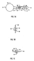
- Figures 1A and 1C illustrate positions of the key 100 in the lock 300.
- the key 100 for an electromechanical lock 300 comprises a first 118 shape configured to engage, during the insertion of the key 100, with the key follower 200 of the lock 300 to mechanically transmit mechanical power produced by a user of the lock 300 to the electric generator 330 of the lock 300.
- the key 100 also comprises a second shape 110 configured to make the electronic circuit 326 electronically control the actuator 330 so as to set the lock 300 to the mechanically openable state provided that data read from a source external to the lock 300 matches a predetermined criterion.
- the key 100 also comprises a third shape 116 configured to engage, during a removal phase of the key 100 by the user, with the key follower 200 to return the key follower 200 to a starting position and mechanically reset the actuator 330 to the locked state.
- Either the first shape 118 or the second shape 110 may also be configured to engage, during the insertion of the key 100, with the key follower 200 to mechanically enable operation of the actuator 330.
- the second shape 110 is configured to engage, during the insertion of the key 100, with the key follower 200 to mechanically enable operation of the actuator 330.
- the first shape 118 is configured to engage, during the insertion of the key 100, with the key follower 200 to mechanically enable operation of the actuator 608.
- the key 100 may also comprise a gap 114, positioned between the first shape 118 and the second shape 110, configured to provide, during the insertion of the key 100, a delay for generating electric power, and for an electronic circuit 326 of the lock 300 to read the data from the source external to the lock 300, and match the data against the predetermined criterion.
- the key 100 may also comprise an electronic circuit 106 configured to store the data.
- the electronic circuit 106 may be an iButton®, for example.
- the key 100 may be configured to engage with a lock cylinder 120 of the lock and together with the lock cylinder 120 be rotatable from a key 100 insertion position to a lock open position.
- the key 100 may also comprise a fourth shape 104, such as a rotating position shape, configured to engage with the lock 300 so that the key 100 is removable from the lock 300 only in the key insertion position.
- the lock 300 comprises the lock cylinder 120 configured to be rotatable from a key 100 insertion position to a lock 300 open position, and the lock 300 may be configured so that the key 100 is only removable in the key 100 insertion position.
- the key 100 may also comprise various other parts. As illustrated in Figure 1A , the key 100 may also comprise a key grip 101 and a key body 102 (in the form of a bar, for example). The key 100 may also comprise key electronics 106 connected to a sliding contact 108 and the key body 102. The key electronics 106 may comprise, as mentioned earlier, the electronic circuit for storing the data (read by the electronic circuit 326 of the lock 300). The key body 102 may also have axial guides for better positioning control.
- the key 100 is shown in a zero position. In the zero position the key 100 may be inserted in or withdrawn from the lock 300 through the keyway shape 122.
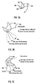
- the key follower 200 may be a rotating key follower described in Figure 2A , but also other forms may be suited for the implementation.
- the rotating key follower 200 may rotate around a shaft 208.
- this principle may be applied by the skilled person for the implementation of the key 100 and its follower 200.
- the key follower 200 comprises a first claw 202 configured to engage with the key 100 during the first insertion phase.
- the key follower 200 also comprises a second claw 204 configured to engage with the key 100 during the second insertion phase and the third insertion phase.
- the key follower 200 may also comprise a swing lever 206.
- Figure 2B illustrates the positions and functions of the key follower 200 when the key 100 is inserted into the lock 300:
- Figure 2C illustrates the positions and functions of the key follower 200 when the key 100 is withdrawn from the lock 300: the key follower 200 may be returned to the gap 114 position by a spring, whereby the position switch 328 is deactivated and the actuator 330 is reset, and after that the third shape 116 of the key 100 may return the key follower 200 to its home position.
- Figure 3J will further illustrate these operations.
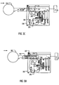
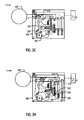
- FIG. 3A illustrates many other possible components of the lock 300.
- the lock 300 may further comprise keyways 122, 306, an electric contact 302, a support 342, a driving pin 316, a locking pin 318, a lever 320, an arm 314, springs 322, 324, 344, a threshold device 332, a clutch 334, a main wheel 338, a stopper 340, a position switch 328, a lock cylinder 120, and a clutch opener 336.
- the lock may be coupled to bolt mechanism 312.
- the electric generator 330 may rotate through the main wheel 338 when the threshold device 332 is moving, provided that the clutch 334 is closed.
- the support 342 may be configured to move by electric power to a fulcrum position provided that the data matches the predetermined criterion, i.e. provided that the data is authenticated.
- the support 342 may be configured to be reset from the fulcrum position with mechanical power when the key is removed from the lock 300.
- the mechanical power may be provided by the spring 344, for example.
- the locking pin 318 may be configured to hold the lock 300, when engaged, in a locked state, and, when disengaged, in a mechanically openable state.
- the locking pin 318 may be configured to engage with mechanical power when the key is removed from the lock.
- the mechanical power may be provided by the spring 322, for example. This is explained below in connection with Figure 3J .
- the locking pin 318 may be configured to implement the locked state so that, when engaged, the locking pin 318 holds the lock cylinder 120 stationary, and to implement the mechanically openable state so that, when disengaged, the locking pin 318 releases the lock cylinder 120 rotatable by mechanical power.
- the input effort is higher than the output load, but the input effort moves through a shorter distance than the load, i.e.
- the locking pin 318 may securely hold the lock cylinder 120 in place in the locked state as the locking pin 318 penetrates deep enough into the wall of the lock cylinder 120.
- a cavity 310 may be formed in the lock cylinder 120 for the locking pin 318.
- the lever 320 may be configured to receive mechanical power, and to output the mechanical power to mechanically disengage the locking pin 318 provided that the support 342 is in the fulcrum position.
- the driving pin 316 may be configured to input the mechanical power to the lever 320.
- the lever 320 may be configured to receive the mechanical power from an insertion of a key.
- the lever 320 may be a third-class lever: the fulcrum is at the left-hand end of the lever 320, the mechanical power is inputted into the middle of the lever 320, and the mechanical power is outputted from the right-hand end of the lever 320.
- a coupling 321 between the lever 320 and the locking pin 318 may act as another fulcrum, and the locking pin 318 remains stationary in a locked position provided that the data does not match the predetermined criterion, i.e. provided that the support 342 is not moved to the fulcrum position.
- Figure 3B illustrates the lock status when the first shape 118 of the key 100 is inserted against the first claw 202 in the lock 300.
- the key electronics 106 may be connected to the electronic circuit 326 so that one electrical connection is made between the electric contact 302 and the slide contact 108, and the other electrical connection between the key body 102 and the lock frame 300.
- the key 100 is inserted to a threshold position in the lock 300: the first shape 118 of the key 100 is still in contact with the first claw 202.
- the threshold device 332 is armed by the swing lever 206.
- the threshold device 332 is launched and it returns to the home position by a spring. Electric power is produced by the electric generator 330 to the electronic circuit 326 when the threshold device 332 is moving.
- the threshold device 332 is illustrated in more detail in other applications by the applicant: EP 05 112 272.9 and PCT/FI2006/050543 .
- the key 100 continues to move into the lock 300.
- the key follower 200 is not moving because the second claw 204 is in the gap 114 of the key 100: delay is made for the electric power generation and the communication.
- the electronic circuit 326 starts, communicates with the key electronics 106 through the electric contacts 302, 108, and authenticates the key 100.
- the actuator enabling operation is started before the power generation phase is ended, i.e. the key 100 may be inserted too fast into the lock 300.
- the actuator operation is disabled, because the clutch 334 may only be opened when it is returned to the home position against to the stopper 340.
- the lock 300 cannot be opened.
- the clutch 334 is opened and the position switch 328 is activated by the second claw 204 and the end of the second shape 110 of the key.
- the electronic circuit 326 controls the generator 330 as an electric motor when the position switch 328 is activated as follows: the generator 330 is driven in the open direction as illustrated in Figures 5E and 5F , if the key 100 is authenticated, and kept in the closed position as illustrated in Figures 5C and 5D , if the key 100 is not authenticated.
- the main wheel 338 is driven to the open position by the electronic circuit 326.
- the support 342 is set under the lever 320.
- the arm 314 and the driving pin 316 are pushed down by the first shape 118 of the key 100, and the locking pin 318 is pushed down through the lever 320 by the driving pin 316.
- the lock 300 is in the mechanically openable state, and the bolt mechanism 312 may be moved by rotating the key 100.
- the lock cylinder 120 provides support for the second claw 204 of the key follower 200 so that it keeps its position during rotation.
- the key 100 has to be returned to the zero position, as illustrated in Figure 1B , before it may be withdrawn from the lock 300.
- the opening is also illustrated in Figures 5C and 5D .
- the clutch 334 is opened and rotation of the main wheel 338 is enabled by the shapes 504, 506.
- the main wheel 338 is rotated by the electric generator 330 to the stopper 508, the support 342 is set under the lever 320, and the locking pin 318 may be opened by the user of the key 100 through the arm 314, the driving pin 316 and the lever 320.
- Figure 4A illustrates the order of the lock functions when the key 100 is inserted into the lock 300 in a specified speed. From the key 100 insertion, linear mechanical power is received. Electric power is generated with a part of the received linear mechanical power. A processor of the lock electronics 326 starts when sufficient voltage is generated and it stops when voltage drops below a sufficient level. The key 100 is authenticated with the generated electric power. The actuator is enabled with the mechanical power.
- the position switch 328 is activated after the key 100 has been inserted in a required depth. Thereupon, the actuator is controlled with the generated electric power, and the lock mechanism is further operated with the mechanical power. If the insertion speed of the key 100 is so slow that the voltage drops below the sufficient level before the position switch 328 is activated, the actuator 330 is not driven, and the lock 300 remains in the locked state. If the key 100 is inserted too fast, the position switch 328 is activated before the key authentication process is ready, and the lock 300 is kept in the closed state. Finally, rotating mechanical power is received and used to operate the bolt mechanism 312.
- Figure 4B illustrates the lock functions when the key 100 is withdrawn from the lock 300.
- Linear mechanical power is received from the key 100 removal.
- the lock mechanism is operated, and, after the position switch 328 is deactivated, the actuator is reset. Thereupon, the key follower 200 is turned to the start position with the mechanical power.
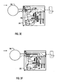
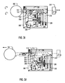
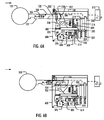
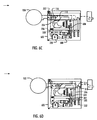
- Figure 6A illustrates an embodiment of a user-powered electromechanical lock 600 comprising a separate generator 606 and an actuator 608.
- the generator 606 may be implemented with any suitable technology capable of generating electric power from mechanical power: an electric generator or a piezoelectric generator may be used as the generator 606, for example.
- the actuator 608 may be implemented with any suitable technology capable of being operated with the electric power so that the lock is set from a locked state to a mechanically openable state: an electric solenoid, a piezoelectric actuator, or an electric motor may be used as the actuator 608, for example.
- an electric motor type actuator 606 turns a gear 616 and the support wheel 604. Electric power is generated by the electric generator 606, which may rotate through gears 612, 614 when the threshold device 332 is moving.
- the lock 600 may comprise the lock cylinder 120, the keyways 122, 306, the electric contact 302, the key follower 200, the arm 314, the driving pin 316, the locking pin 318, the lever 320, the springs 322, 324, 602, the electronic circuit 326, the position switch 328, a support wheel 604, and a bar 610. Furthermore, the lock 600 may be coupled to the bolt mechanism 312.
- Figure 6A illustrates the lock status when the key 100 is inserted against the first claw 202 of the key follower 200.
- the key electronics 106 may be connected to the electronic circuit 326 so that one electrical connection is made between the electric contact 302 and the slide contact 108, and the other electrical connection between the key body 102 and the frame of the lock 600.
- the support wheel 604 is kept in the locked position by the bar 610 and its spring 602.
- Actuator reset and enable operations are similar to shapes 506 and 504 illustrated in Figures 5B, 5D and 5F , but in the embodiment of Figure 6A the clutch 334 is replaced by the right-hand end of the bar 610 having the shape 504.
- the key 100 is inserted over the threshold position, prior to which the threshold device 332 is armed and launched. Electric power is produced through gears 612, 614 and the threshold device 332 by the generator 606.
- the electronic circuit 326 is started and communication between the lock 600 and the key 100 is in progress.
- the key follower 200 is not moving even though the key 100 is moving in, because the second claw 204 of the key follower 200 is in the gap 114 of the key 100. Thereby, time for energy production and key 100 authentication is arranged.
- the second claw 204 of the key follower 200 is pushed forward by the second shape 110 of the key 100.
- the actuator operation is enabled by removing the bar 610 from the support wheel 604 with the swing lever 206.
- the position switch 328 is activated, the actuator 608 is controlled, and support wheel 604 is turned to open position provided that the key 100 is authenticated.
- the actuator 608 is kept in the closed position if the key 100 is not authenticated.
- the support wheel 604 is kept in the closed position.
- the support 342 is not set under the lever 320.
- the arm 314, the driving pin 316 and the lever 320 are pushed down by the first shape 118 of the key, but the locking pin 318 is kept in the closed position by the spring 322.
- the lock 600 cannot be opened.
- the support wheel 604 is driven to the open position by the electronic circuit 326.
- the support 342 is set under the lever 320.
- the arm 314 and the driving pin 316 are pushed down by the first shape 118 of the key, and the lever 320 ejects the locking pin 318 from the lock cylinder 120.
- the lock 600 is set to the mechanically openable state, and the bolt mechanism 312 may be moved by rotating the key 100. While the key 100 is rotated, the lock cylinder 120 provides support for the second claw 204 of the key follower 200 so that it retains its position during rotation.
- the key shape 104 and the keyway shape 122 ensure that the key 100 returns to the zero position as illustrated in Figure 1B before it may be withdrawn from the lock 600.
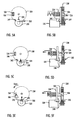
- Figure 7A illustrates a key 700 according to the claimed invention, which comprises a key body 702 and key electronics 706.
- the key body 702 may comprise different shapes: a rotating position shape 704, a first shape 718, a second shape 710 and a third shape 716, a gap 708, a recess 703, and a guide 712.
- the key electronics 706 may communicate wirelessly with a lock.
- Figure 7B illustrates according to the claimed invention, the key 700 fully inserted in a lock cylinder 720 comprising a track 722 for the second claw 204 of the key follower 200.
- the track 722 enables the rotation of the lock cylinder 720.
- This embodiment illustrates that the key follower 200 may be returned without a spring load when the key 700 is removed from the lock cylinder 720.
- the second claw 204 of the key follower 200 is configured to protrude from the inner wall of the lock cylinder 720 when the key 700 is fully inserted in the lock cylinder 720.
- the recess 703 adjacent to the third shape 716 is configured to enable protrusion of (the second claw 204 of) the key follower 200 into the recess 703 so that during a removal phase of the key 700 the third shape 716 contacts with (the second claw 703 of) the key follower 200 and rotates the key follower 200 to the starting position.
- Figure 7C illustrates according to the claimed invention, a cross-section of the lock cylinder 720 and the key follower 200 when the key 700 is inserted.
- the guide 712 of the key ensures that the first claw 202 of the key follower cannot drop into the gap 708.
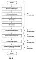
- 802 and 810 may be divided between the first 818 and the second 820 insertion phases as illustrated in Figure 8 , but also another division is possible.
- An example of the other division is that 810 is executed before 802, i.e. both 810 and 802 are performed in the first insertion phase 818 before 804, 806 and 808, and actually neither of 810 and 802 is performed in the second insertion phase 820
- electric power is generated from mechanical power by the electric generator.
- data is read from an external source.
- the data is matched against a predetermined criterion.
- the electric power generation in 804 may continue at least partly in parallel with 806 and possibly also with 808.
- the actuator may be electronically controlled to set the lock to a mechanically openable state with electric power provided that the data matches the predetermined criterion in 812.
- the lock may be mechanically opened in a fourth insertion phase 824 of the key.
- the fourth insertion phase 824 may include the opening of the locking pin by levering it, and the turning of the bolt mechanism after the key has reached the allowed maximum insertion depth.
- the key follower is returned to a starting position and the actuator is mechanically reset to the locked state in 815.
- the method may be enhanced with the embodiments of the electromechanical lock and the key described earlier.
Landscapes
- Engineering & Computer Science (AREA)
- Computer Networks & Wireless Communication (AREA)
- Physics & Mathematics (AREA)
- General Physics & Mathematics (AREA)
- Lock And Its Accessories (AREA)
Priority Applications (10)
| Application Number | Priority Date | Filing Date | Title |
|---|---|---|---|
| ES07112676T ES2386819T3 (es) | 2007-07-18 | 2007-07-18 | Cerradura electromecánica |
| EP20070112676 EP2017795B1 (en) | 2007-07-18 | 2007-07-18 | Electromechanical lock |
| PL07112676T PL2017795T3 (pl) | 2007-07-18 | 2007-07-18 | Zamek elektromechaniczny |
| PCT/FI2008/050435 WO2009010638A1 (en) | 2007-07-18 | 2008-07-16 | Electromechanical lock and its key |
| CN2008800250160A CN101755289B (zh) | 2007-07-18 | 2008-07-16 | 电动机械锁及其钥匙 |
| CA 2729007 CA2729007C (en) | 2007-07-18 | 2008-07-16 | Electromechanical lock and its key |
| US12/669,209 US8468861B2 (en) | 2007-07-18 | 2008-07-16 | Electromechanical lock and its key |
| RU2010103940/08A RU2472223C2 (ru) | 2007-07-18 | 2008-07-16 | Электромеханическое запорное устройство и ключ, предназначенный для этого устройства |
| KR1020107002043A KR101258551B1 (ko) | 2007-07-18 | 2008-07-16 | 전기기계식 잠금 장치 및 그의 열쇠 |
| JP2010516532A JP5295235B2 (ja) | 2007-07-18 | 2008-07-16 | 電子機械式ロックおよびそのキー |
Applications Claiming Priority (1)
| Application Number | Priority Date | Filing Date | Title |
|---|---|---|---|
| EP20070112676 EP2017795B1 (en) | 2007-07-18 | 2007-07-18 | Electromechanical lock |
Publications (2)
| Publication Number | Publication Date |
|---|---|
| EP2017795A1 EP2017795A1 (en) | 2009-01-21 |
| EP2017795B1 true EP2017795B1 (en) | 2012-06-13 |
Family
ID=38728648
Family Applications (1)
| Application Number | Title | Priority Date | Filing Date |
|---|---|---|---|
| EP20070112676 Active EP2017795B1 (en) | 2007-07-18 | 2007-07-18 | Electromechanical lock |
Country Status (10)
| Country | Link |
|---|---|
| US (1) | US8468861B2 (pl) |
| EP (1) | EP2017795B1 (pl) |
| JP (1) | JP5295235B2 (pl) |
| KR (1) | KR101258551B1 (pl) |
| CN (1) | CN101755289B (pl) |
| CA (1) | CA2729007C (pl) |
| ES (1) | ES2386819T3 (pl) |
| PL (1) | PL2017795T3 (pl) |
| RU (1) | RU2472223C2 (pl) |
| WO (1) | WO2009010638A1 (pl) |
Cited By (1)
| Publication number | Priority date | Publication date | Assignee | Title |
|---|---|---|---|---|
| US9574376B2 (en) | 2012-06-12 | 2017-02-21 | Iloq Oy | Electromechanical lock |
Families Citing this family (24)
| Publication number | Priority date | Publication date | Assignee | Title |
|---|---|---|---|---|
| EP2017412B1 (en) | 2007-07-18 | 2015-10-14 | iLOQ Oy | Electromechanical lock |
| PL2017413T3 (pl) | 2007-07-18 | 2017-12-29 | Iloq Oy | Zamek elektromechaniczny |
| DE102008018906B4 (de) * | 2008-04-14 | 2011-06-30 | ASTRA Gesellschaft für Asset Management mbH & Co. KG, 30890 | Schließzylinderanordnung |
| CH700674A1 (de) * | 2009-03-30 | 2010-09-30 | Keso Ag | Mechatronische schliessvorrichtung. |
| ES2392387T3 (es) * | 2010-01-15 | 2012-12-10 | Iloq Oy | Cerradura electromecánica |
| US9186642B2 (en) | 2010-04-28 | 2015-11-17 | The Procter & Gamble Company | Delivery particle |
| US10465422B2 (en) | 2012-05-10 | 2019-11-05 | 2603701 Ontario Inc. | Electronic lock mechanism |
| US9663972B2 (en) | 2012-05-10 | 2017-05-30 | Wesko Locks Ltd. | Method and system for operating an electronic lock |
| US9704316B2 (en) | 2013-09-10 | 2017-07-11 | Gregory Paul Kirkjan | Contactless electronic access control system |
| DE102016201198A1 (de) * | 2016-01-27 | 2017-07-27 | Gerd Reime | Sicherungs- und/oder Verriegelungssystem sowie zugehöriges Verfahren |
| EP3270357B1 (en) * | 2016-07-14 | 2019-03-13 | KALE Kilit ve Kalip Sanayi A.S. | Electronic lock |
| CN110114541B (zh) | 2016-10-19 | 2021-08-13 | 多玛凯拔美国股份有限公司 | 电子机械锁芯 |
| ES2765814T3 (es) | 2017-02-16 | 2020-06-11 | Iloq Oy | Cerradura electromecánica |
| SG11201909152TA (en) * | 2017-04-04 | 2019-10-30 | Abloy Oy | Cylinder lock |
| EP3679207B1 (en) | 2017-09-08 | 2022-08-03 | Dormakaba USA Inc. | Electro-mechanical lock core |
| EP3533955B1 (en) * | 2018-03-02 | 2020-11-04 | Assa Abloy AB | Electronic locking system with energy harvesting arrangement |
| US11466473B2 (en) | 2018-04-13 | 2022-10-11 | Dormakaba Usa Inc | Electro-mechanical lock core |
| CA3097041C (en) | 2018-04-13 | 2022-10-25 | Dormakaba Usa Inc. | Electro-mechanical lock core |
| CN110544330A (zh) * | 2019-08-05 | 2019-12-06 | 浙江西谷数字技术股份有限公司 | 智能锁及其用于智能锁的超低功耗rf模块收发方法 |
| KR102127698B1 (ko) * | 2019-11-29 | 2020-06-29 | 주식회사 브이엠테크 | 이중 발전을 이용하여 동작하는 잠금 장치 |
| US11574513B2 (en) | 2020-03-31 | 2023-02-07 | Lockfob, Llc | Electronic access control |
| KR102340379B1 (ko) * | 2020-05-06 | 2021-12-17 | 주식회사 브이엠테크 | 스마트폰과 연동하는 이중 발전을 이용하는 잠금 장치 |
| JP7190466B2 (ja) * | 2020-09-04 | 2022-12-15 | 日本金銭機械株式会社 | 施解錠装置 |
| FR3143222A1 (fr) * | 2022-12-12 | 2024-06-14 | Nexialiste Normand | Système multi contacts électriques avec clef à zones isolantes |
Citations (1)
| Publication number | Priority date | Publication date | Assignee | Title |
|---|---|---|---|---|
| US5132661A (en) * | 1987-10-02 | 1992-07-21 | Universal Photonix, Inc. | Security system employing optical key shape reader |
Family Cites Families (21)
| Publication number | Priority date | Publication date | Assignee | Title |
|---|---|---|---|---|
| FR1321583A (fr) | 1962-02-09 | 1963-03-22 | Moreaux & Cie | Perfectionnements aux serrures à fonctionnement automatique |
| FR2467116A1 (fr) * | 1979-10-12 | 1981-04-17 | Sodex Magister | Perfectionnements aux antivols pour vehicules automobiles |
| DE3208818C2 (de) * | 1982-03-11 | 1985-11-07 | Fa. Aug. Winkhaus, 4404 Telgte | Elektrisch entriegelbares Schloß mit lokaler Stromversorgung und piezoelektrischem Blockierriegel |
| US4601184A (en) * | 1983-09-16 | 1986-07-22 | Fichet Bauche | Safety lock |
| US4912460A (en) * | 1987-07-16 | 1990-03-27 | John Chu | Electrostatically activated gating mechanism |
| EP0339102A1 (de) | 1988-04-26 | 1989-11-02 | Herz GmbH | Mechanische Energieumsetzung in elektrische für Betrieb von Elektronik und Elektromechanik in elektromechanischen Verschlusseinrichtungen |
| AT400256B (de) * | 1992-03-02 | 1995-11-27 | Evva Werke | Energieversorgungseinrichtung |
| US5677682A (en) * | 1992-08-05 | 1997-10-14 | Thorsen; Anders Christian | Electronic lock system |
| US5493882A (en) * | 1993-05-07 | 1996-02-27 | Lockmasters, Inc. | Drive apparatus and portable power source for computerized combination locks |
| DE19519789B4 (de) * | 1995-06-02 | 2007-06-21 | Bks Gmbh | Schloß mit Schließzylinder |
| IT1297493B1 (it) * | 1997-10-03 | 1999-12-17 | Silca Spa | Unita' di cilindro e chiave a funzionamento meccatronico per serratura |
| US6442986B1 (en) * | 1998-04-07 | 2002-09-03 | Best Lock Corporation | Electronic token and lock core |
| DE19908085C1 (de) * | 1999-02-25 | 2000-06-21 | Huf Huelsbeck & Fuerst Gmbh | Vorrichtung zur Aufnahme und Halterung eines Identifikationsgebers, wie eines elektronischen Schlüssels, insbesondere für einen Zündanlaßschalter und/oder eine Lenksäuleneverriegelung eines Motorfahrzeugs |
| US6389856B1 (en) * | 1999-06-11 | 2002-05-21 | Nissan Motor Co., Ltd. | Lock apparatus |
| DE19939733C2 (de) * | 1999-08-21 | 2001-10-11 | Huf Huelsbeck & Fuerst Gmbh | Vorrichtung zum Starten eines Fahrzeugmotors mittels eines elektronischen Schlüssels |
| RU2174581C1 (ru) * | 2000-07-20 | 2001-10-10 | Башкин Анатолий Иванович | Электромеханический замок |
| RU2261976C2 (ru) * | 2003-09-08 | 2005-10-10 | Федеральное государственное унитарное предприятие "Производственное объединение "Старт" | Электромеханический замок |
| ES2343355T3 (es) | 2005-12-16 | 2010-07-29 | Iloq Oy | Cerradura electromecanica y su metodo de funcionamiento. |
| US7334441B1 (en) * | 2007-01-16 | 2008-02-26 | Lear Corporation | Electronic vehicle key and housing assembly |
| PL2017413T3 (pl) | 2007-07-18 | 2017-12-29 | Iloq Oy | Zamek elektromechaniczny |
| EP2017412B1 (en) | 2007-07-18 | 2015-10-14 | iLOQ Oy | Electromechanical lock |
-
2007
- 2007-07-18 EP EP20070112676 patent/EP2017795B1/en active Active
- 2007-07-18 PL PL07112676T patent/PL2017795T3/pl unknown
- 2007-07-18 ES ES07112676T patent/ES2386819T3/es active Active
-
2008
- 2008-07-16 RU RU2010103940/08A patent/RU2472223C2/ru active
- 2008-07-16 CN CN2008800250160A patent/CN101755289B/zh active Active
- 2008-07-16 WO PCT/FI2008/050435 patent/WO2009010638A1/en not_active Ceased
- 2008-07-16 KR KR1020107002043A patent/KR101258551B1/ko active Active
- 2008-07-16 US US12/669,209 patent/US8468861B2/en active Active
- 2008-07-16 CA CA 2729007 patent/CA2729007C/en active Active
- 2008-07-16 JP JP2010516532A patent/JP5295235B2/ja active Active
Patent Citations (1)
| Publication number | Priority date | Publication date | Assignee | Title |
|---|---|---|---|---|
| US5132661A (en) * | 1987-10-02 | 1992-07-21 | Universal Photonix, Inc. | Security system employing optical key shape reader |
Cited By (1)
| Publication number | Priority date | Publication date | Assignee | Title |
|---|---|---|---|---|
| US9574376B2 (en) | 2012-06-12 | 2017-02-21 | Iloq Oy | Electromechanical lock |
Also Published As
| Publication number | Publication date |
|---|---|
| US20100139343A1 (en) | 2010-06-10 |
| CN101755289B (zh) | 2012-08-08 |
| ES2386819T3 (es) | 2012-08-31 |
| EP2017795A1 (en) | 2009-01-21 |
| RU2472223C2 (ru) | 2013-01-10 |
| PL2017795T3 (pl) | 2012-10-31 |
| CA2729007C (en) | 2014-08-26 |
| JP5295235B2 (ja) | 2013-09-18 |
| RU2010103940A (ru) | 2011-08-27 |
| CA2729007A1 (en) | 2009-01-22 |
| JP2010533807A (ja) | 2010-10-28 |
| KR101258551B1 (ko) | 2013-05-06 |
| WO2009010638A1 (en) | 2009-01-22 |
| CN101755289A (zh) | 2010-06-23 |
| KR20100039367A (ko) | 2010-04-15 |
| US8468861B2 (en) | 2013-06-25 |
Similar Documents
| Publication | Publication Date | Title |
|---|---|---|
| EP2017795B1 (en) | Electromechanical lock | |
| EP2017413B1 (en) | Electromechanical lock | |
| EP2017412B1 (en) | Electromechanical lock | |
| EP2674552B1 (en) | Electromechanical lock | |
| CN110249102B (zh) | 电子机械锁 | |
| EP1786998B1 (en) | Electromechanical programmable lock and its operating system | |
| CN201087630Y (zh) | 保管箱电容式指纹锁 | |
| JP2020051187A (ja) | 鍵機構 | |
| CN104632002A (zh) | 一种低功耗蓝牙保险箱 |
Legal Events
| Date | Code | Title | Description |
|---|---|---|---|
| PUAI | Public reference made under article 153(3) epc to a published international application that has entered the european phase |
Free format text: ORIGINAL CODE: 0009012 |
|
| AK | Designated contracting states |
Kind code of ref document: A1 Designated state(s): AT BE BG CH CY CZ DE DK EE ES FI FR GB GR HU IE IS IT LI LT LU LV MC MT NL PL PT RO SE SI SK TR |
|
| AX | Request for extension of the european patent |
Extension state: AL BA HR MK RS |
|
| 17P | Request for examination filed |
Effective date: 20090608 |
|
| AKX | Designation fees paid |
Designated state(s): AT BE BG CH CY CZ DE DK EE ES FI FR GB GR HU IE IS IT LI LT LU LV MC MT NL PL PT RO SE SI SK TR |
|
| 17Q | First examination report despatched |
Effective date: 20110120 |
|
| GRAP | Despatch of communication of intention to grant a patent |
Free format text: ORIGINAL CODE: EPIDOSNIGR1 |
|
| RTI1 | Title (correction) |
Free format text: ELECTROMECHANICAL LOCK |
|
| GRAS | Grant fee paid |
Free format text: ORIGINAL CODE: EPIDOSNIGR3 |
|
| RIN1 | Information on inventor provided before grant (corrected) |
Inventor name: PAEAEKKOENEN, TOIVO Inventor name: JOKINEN, HANNU Inventor name: KARJALAINEN, PETTERI Inventor name: PUKARI, MIKA |
|
| GRAA | (expected) grant |
Free format text: ORIGINAL CODE: 0009210 |
|
| RAP1 | Party data changed (applicant data changed or rights of an application transferred) |
Owner name: ILOQ OY |
|
| AK | Designated contracting states |
Kind code of ref document: B1 Designated state(s): AT BE BG CH CY CZ DE DK EE ES FI FR GB GR HU IE IS IT LI LT LU LV MC MT NL PL PT RO SE SI SK TR |
|
| REG | Reference to a national code |
Ref country code: GB Ref legal event code: FG4D |
|
| REG | Reference to a national code |
Ref country code: AT Ref legal event code: REF Ref document number: 562285 Country of ref document: AT Kind code of ref document: T Effective date: 20120615 Ref country code: CH Ref legal event code: EP |
|
| REG | Reference to a national code |
Ref country code: IE Ref legal event code: FG4D |
|
| REG | Reference to a national code |
Ref country code: NL Ref legal event code: T3 |
|
| REG | Reference to a national code |
Ref country code: DE Ref legal event code: R096 Ref document number: 602007023286 Country of ref document: DE Effective date: 20120809 |
|
| REG | Reference to a national code |
Ref country code: ES Ref legal event code: FG2A Ref document number: 2386819 Country of ref document: ES Kind code of ref document: T3 Effective date: 20120831 |
|
| REG | Reference to a national code |
Ref country code: SE Ref legal event code: TRGR |
|
| PG25 | Lapsed in a contracting state [announced via postgrant information from national office to epo] |
Ref country code: CY Free format text: LAPSE BECAUSE OF FAILURE TO SUBMIT A TRANSLATION OF THE DESCRIPTION OR TO PAY THE FEE WITHIN THE PRESCRIBED TIME-LIMIT Effective date: 20120613 Ref country code: LT Free format text: LAPSE BECAUSE OF FAILURE TO SUBMIT A TRANSLATION OF THE DESCRIPTION OR TO PAY THE FEE WITHIN THE PRESCRIBED TIME-LIMIT Effective date: 20120613 |
|
| REG | Reference to a national code |
Ref country code: PL Ref legal event code: T3 |
|
| REG | Reference to a national code |
Ref country code: LT Ref legal event code: MG4D Effective date: 20120613 |
|
| PG25 | Lapsed in a contracting state [announced via postgrant information from national office to epo] |
Ref country code: SI Free format text: LAPSE BECAUSE OF FAILURE TO SUBMIT A TRANSLATION OF THE DESCRIPTION OR TO PAY THE FEE WITHIN THE PRESCRIBED TIME-LIMIT Effective date: 20120613 Ref country code: LV Free format text: LAPSE BECAUSE OF FAILURE TO SUBMIT A TRANSLATION OF THE DESCRIPTION OR TO PAY THE FEE WITHIN THE PRESCRIBED TIME-LIMIT Effective date: 20120613 Ref country code: GR Free format text: LAPSE BECAUSE OF FAILURE TO SUBMIT A TRANSLATION OF THE DESCRIPTION OR TO PAY THE FEE WITHIN THE PRESCRIBED TIME-LIMIT Effective date: 20120914 |
|
| PG25 | Lapsed in a contracting state [announced via postgrant information from national office to epo] |
Ref country code: IS Free format text: LAPSE BECAUSE OF FAILURE TO SUBMIT A TRANSLATION OF THE DESCRIPTION OR TO PAY THE FEE WITHIN THE PRESCRIBED TIME-LIMIT Effective date: 20121013 Ref country code: RO Free format text: LAPSE BECAUSE OF FAILURE TO SUBMIT A TRANSLATION OF THE DESCRIPTION OR TO PAY THE FEE WITHIN THE PRESCRIBED TIME-LIMIT Effective date: 20120613 Ref country code: BE Free format text: LAPSE BECAUSE OF FAILURE TO SUBMIT A TRANSLATION OF THE DESCRIPTION OR TO PAY THE FEE WITHIN THE PRESCRIBED TIME-LIMIT Effective date: 20120613 Ref country code: CZ Free format text: LAPSE BECAUSE OF FAILURE TO SUBMIT A TRANSLATION OF THE DESCRIPTION OR TO PAY THE FEE WITHIN THE PRESCRIBED TIME-LIMIT Effective date: 20120613 Ref country code: EE Free format text: LAPSE BECAUSE OF FAILURE TO SUBMIT A TRANSLATION OF THE DESCRIPTION OR TO PAY THE FEE WITHIN THE PRESCRIBED TIME-LIMIT Effective date: 20120613 Ref country code: SK Free format text: LAPSE BECAUSE OF FAILURE TO SUBMIT A TRANSLATION OF THE DESCRIPTION OR TO PAY THE FEE WITHIN THE PRESCRIBED TIME-LIMIT Effective date: 20120613 |
|
| PG25 | Lapsed in a contracting state [announced via postgrant information from national office to epo] |
Ref country code: MC Free format text: LAPSE BECAUSE OF NON-PAYMENT OF DUE FEES Effective date: 20120731 Ref country code: PT Free format text: LAPSE BECAUSE OF FAILURE TO SUBMIT A TRANSLATION OF THE DESCRIPTION OR TO PAY THE FEE WITHIN THE PRESCRIBED TIME-LIMIT Effective date: 20121015 |
|
| REG | Reference to a national code |
Ref country code: CH Ref legal event code: PL |
|
| PLBE | No opposition filed within time limit |
Free format text: ORIGINAL CODE: 0009261 |
|
| STAA | Information on the status of an ep patent application or granted ep patent |
Free format text: STATUS: NO OPPOSITION FILED WITHIN TIME LIMIT |
|
| PG25 | Lapsed in a contracting state [announced via postgrant information from national office to epo] |
Ref country code: DK Free format text: LAPSE BECAUSE OF FAILURE TO SUBMIT A TRANSLATION OF THE DESCRIPTION OR TO PAY THE FEE WITHIN THE PRESCRIBED TIME-LIMIT Effective date: 20120613 Ref country code: CH Free format text: LAPSE BECAUSE OF NON-PAYMENT OF DUE FEES Effective date: 20120731 Ref country code: LI Free format text: LAPSE BECAUSE OF NON-PAYMENT OF DUE FEES Effective date: 20120731 |
|
| REG | Reference to a national code |
Ref country code: IE Ref legal event code: MM4A |
|
| 26N | No opposition filed |
Effective date: 20130314 |
|
| REG | Reference to a national code |
Ref country code: DE Ref legal event code: R097 Ref document number: 602007023286 Country of ref document: DE Effective date: 20130314 |
|
| PG25 | Lapsed in a contracting state [announced via postgrant information from national office to epo] |
Ref country code: BG Free format text: LAPSE BECAUSE OF FAILURE TO SUBMIT A TRANSLATION OF THE DESCRIPTION OR TO PAY THE FEE WITHIN THE PRESCRIBED TIME-LIMIT Effective date: 20120913 Ref country code: IE Free format text: LAPSE BECAUSE OF NON-PAYMENT OF DUE FEES Effective date: 20120718 Ref country code: MT Free format text: LAPSE BECAUSE OF FAILURE TO SUBMIT A TRANSLATION OF THE DESCRIPTION OR TO PAY THE FEE WITHIN THE PRESCRIBED TIME-LIMIT Effective date: 20120613 |
|
| PG25 | Lapsed in a contracting state [announced via postgrant information from national office to epo] |
Ref country code: TR Free format text: LAPSE BECAUSE OF FAILURE TO SUBMIT A TRANSLATION OF THE DESCRIPTION OR TO PAY THE FEE WITHIN THE PRESCRIBED TIME-LIMIT Effective date: 20120613 |
|
| PG25 | Lapsed in a contracting state [announced via postgrant information from national office to epo] |
Ref country code: LU Free format text: LAPSE BECAUSE OF NON-PAYMENT OF DUE FEES Effective date: 20120718 |
|
| PG25 | Lapsed in a contracting state [announced via postgrant information from national office to epo] |
Ref country code: HU Free format text: LAPSE BECAUSE OF FAILURE TO SUBMIT A TRANSLATION OF THE DESCRIPTION OR TO PAY THE FEE WITHIN THE PRESCRIBED TIME-LIMIT Effective date: 20070718 |
|
| REG | Reference to a national code |
Ref country code: FR Ref legal event code: PLFP Year of fee payment: 10 |
|
| REG | Reference to a national code |
Ref country code: FR Ref legal event code: PLFP Year of fee payment: 11 |
|
| REG | Reference to a national code |
Ref country code: FR Ref legal event code: PLFP Year of fee payment: 12 |
|
| PGFP | Annual fee paid to national office [announced via postgrant information from national office to epo] |
Ref country code: PL Payment date: 20250623 Year of fee payment: 19 |
|
| PGFP | Annual fee paid to national office [announced via postgrant information from national office to epo] |
Ref country code: NL Payment date: 20250715 Year of fee payment: 19 |
|
| PGFP | Annual fee paid to national office [announced via postgrant information from national office to epo] |
Ref country code: ES Payment date: 20250812 Year of fee payment: 19 Ref country code: FI Payment date: 20250717 Year of fee payment: 19 |
|
| PGFP | Annual fee paid to national office [announced via postgrant information from national office to epo] |
Ref country code: DE Payment date: 20250721 Year of fee payment: 19 |
|
| PGFP | Annual fee paid to national office [announced via postgrant information from national office to epo] |
Ref country code: IT Payment date: 20250728 Year of fee payment: 19 |
|
| PGFP | Annual fee paid to national office [announced via postgrant information from national office to epo] |
Ref country code: GB Payment date: 20250721 Year of fee payment: 19 |
|
| PGFP | Annual fee paid to national office [announced via postgrant information from national office to epo] |
Ref country code: AT Payment date: 20250721 Year of fee payment: 19 Ref country code: FR Payment date: 20250716 Year of fee payment: 19 |
|
| PGFP | Annual fee paid to national office [announced via postgrant information from national office to epo] |
Ref country code: SE Payment date: 20250723 Year of fee payment: 19 |