EP2017513A1 - Valve control apparatus and flow volume controller - Google Patents
Valve control apparatus and flow volume controller Download PDFInfo
- Publication number
- EP2017513A1 EP2017513A1 EP07742922A EP07742922A EP2017513A1 EP 2017513 A1 EP2017513 A1 EP 2017513A1 EP 07742922 A EP07742922 A EP 07742922A EP 07742922 A EP07742922 A EP 07742922A EP 2017513 A1 EP2017513 A1 EP 2017513A1
- Authority
- EP
- European Patent Office
- Prior art keywords
- section
- voltage
- motor
- valve
- drop
- Prior art date
- Legal status (The legal status is an assumption and is not a legal conclusion. Google has not performed a legal analysis and makes no representation as to the accuracy of the status listed.)
- Pending
Links
- 239000012530 fluid Substances 0.000 claims description 28
- 238000001514 detection method Methods 0.000 claims description 8
- 238000010586 diagram Methods 0.000 description 9
- 230000004913 activation Effects 0.000 description 5
- 230000008878 coupling Effects 0.000 description 5
- 238000010168 coupling process Methods 0.000 description 5
- 238000005859 coupling reaction Methods 0.000 description 5
- 238000000034 method Methods 0.000 description 4
- 239000003990 capacitor Substances 0.000 description 3
- 238000005070 sampling Methods 0.000 description 2
- 230000008901 benefit Effects 0.000 description 1
- 230000008859 change Effects 0.000 description 1
- 230000003111 delayed effect Effects 0.000 description 1
- 238000009434 installation Methods 0.000 description 1
- 230000007257 malfunction Effects 0.000 description 1
- 238000004519 manufacturing process Methods 0.000 description 1
- 230000009467 reduction Effects 0.000 description 1
- 230000004044 response Effects 0.000 description 1
- 239000004065 semiconductor Substances 0.000 description 1
- 239000000126 substance Substances 0.000 description 1
- 230000002459 sustained effect Effects 0.000 description 1
Images


Classifications
-
- H—ELECTRICITY
- H02—GENERATION; CONVERSION OR DISTRIBUTION OF ELECTRIC POWER
- H02P—CONTROL OR REGULATION OF ELECTRIC MOTORS, ELECTRIC GENERATORS OR DYNAMO-ELECTRIC CONVERTERS; CONTROLLING TRANSFORMERS, REACTORS OR CHOKE COILS
- H02P8/00—Arrangements for controlling dynamo-electric motors of the kind having motors rotating step by step
- H02P8/42—Arrangements for controlling dynamo-electric motors of the kind having motors rotating step by step characterised by non-stepper motors being operated step by step
-
- F—MECHANICAL ENGINEERING; LIGHTING; HEATING; WEAPONS; BLASTING
- F16—ENGINEERING ELEMENTS AND UNITS; GENERAL MEASURES FOR PRODUCING AND MAINTAINING EFFECTIVE FUNCTIONING OF MACHINES OR INSTALLATIONS; THERMAL INSULATION IN GENERAL
- F16K—VALVES; TAPS; COCKS; ACTUATING-FLOATS; DEVICES FOR VENTING OR AERATING
- F16K31/00—Actuating devices; Operating means; Releasing devices
- F16K31/02—Actuating devices; Operating means; Releasing devices electric; magnetic
- F16K31/04—Actuating devices; Operating means; Releasing devices electric; magnetic using a motor
-
- F—MECHANICAL ENGINEERING; LIGHTING; HEATING; WEAPONS; BLASTING
- F16—ENGINEERING ELEMENTS AND UNITS; GENERAL MEASURES FOR PRODUCING AND MAINTAINING EFFECTIVE FUNCTIONING OF MACHINES OR INSTALLATIONS; THERMAL INSULATION IN GENERAL
- F16K—VALVES; TAPS; COCKS; ACTUATING-FLOATS; DEVICES FOR VENTING OR AERATING
- F16K37/00—Special means in or on valves or other cut-off apparatus for indicating or recording operation thereof, or for enabling an alarm to be given
- F16K37/0075—For recording or indicating the functioning of a valve in combination with test equipment
- F16K37/0083—For recording or indicating the functioning of a valve in combination with test equipment by measuring valve parameters
-
- G—PHYSICS
- G05—CONTROLLING; REGULATING
- G05D—SYSTEMS FOR CONTROLLING OR REGULATING NON-ELECTRIC VARIABLES
- G05D7/00—Control of flow
- G05D7/06—Control of flow characterised by the use of electric means
-
- G—PHYSICS
- G05—CONTROLLING; REGULATING
- G05D—SYSTEMS FOR CONTROLLING OR REGULATING NON-ELECTRIC VARIABLES
- G05D7/00—Control of flow
- G05D7/06—Control of flow characterised by the use of electric means
- G05D7/0617—Control of flow characterised by the use of electric means specially adapted for fluid materials
- G05D7/0629—Control of flow characterised by the use of electric means specially adapted for fluid materials characterised by the type of regulator means
- G05D7/0635—Control of flow characterised by the use of electric means specially adapted for fluid materials characterised by the type of regulator means by action on throttling means
-
- H—ELECTRICITY
- H02—GENERATION; CONVERSION OR DISTRIBUTION OF ELECTRIC POWER
- H02P—CONTROL OR REGULATION OF ELECTRIC MOTORS, ELECTRIC GENERATORS OR DYNAMO-ELECTRIC CONVERTERS; CONTROLLING TRANSFORMERS, REACTORS OR CHOKE COILS
- H02P8/00—Arrangements for controlling dynamo-electric motors of the kind having motors rotating step by step
- H02P8/24—Arrangements for stopping
- H02P8/26—Memorising final pulse when stopping
Abstract
Description
- The present invention relates to valve control apparatuses for installation in fluid channels to control the flow rate of a fluid, in various industrial fields, including, for example, chemical plants, semiconductor manufacturing, food, and bioindustry, and also relates to flow rate controllers including such valve control apparatuses.
- Examples of conventionally known flow rate controllers for controlling the amount of fluid flowing through a fluid channel include those using pulse motors for open/close control of valves.
A flow rate controller using a pulse motor, for example, controls the position of a valve during driving by counting the number of input pulses and, when the driving is stopped, moves the valve back to its original position before the entire flow rate controller comes to a stop. This control allows the valve to be controlled the next time driving starts on the assumption that the valve is at the original position. - If the power fails for any reason during the operation, the flow rate controller would stop without moving the valve back to the original position. Thus, if the operation stops before the valve is moved back to the original position, control for returning the valve to the original position (hereinafter referred to as the "return-to-origin control") must be performed before the next time driving starts.
- An example of the return-to-origin control is a technique disclosed in
Patent Document 1.
Patent Document 1 discloses a technique for temporarily stopping a pulse motor upon detection of its malfunction while driving it in such a direction as to close a valve, further driving the pulse motor in such a direction as to close the valve by a predetermined number of pulses before stopping the pulse motor, and finally driving the pulse motor in such a direction as to open the valve by a specified number of pulses before stopping the pulse motor, thereby detecting the origin of the valve.
Patent Document 2 discloses a technique, using a position sensor that outputs different signals based on the operating position of a driven part such as a valve, for driving a pulse motor in a predetermined direction upon activation, sampling signals output from the position sensor for each predetermined angle of motor driving during the driving, recognizing the current valve position from the sampling variation pattern, and setting the origin of the valve based on the recognized current position. This technique can reduce the amount of driving of the pulse motor when the motor is returned to its origin because a change in the position of a driven part such as a valve is followed by the updating of the origin, thus quickly enabling normal control. - Patent Document 1:
Japanese Unexamined Patent Application, Publication No.2004-348227 - Patent Document 2:
Japanese Unexamined Patent Application, Publication No.2003-348895 - The invention described in
Patent Document 1 above, however, has a problem in that it tends to cause biting of a screw part for driving the valve because the pulse motor may rotate beyond its range of motion; the apparatus breaks down if the biting is so serious that the pulse motor can no longer be driven.
The invention described inPatent Document 2, on the other hand, has a problem in that it increases the size and cost of the apparatus because the origin is set by identifying the valve position using, for example, a rotary encoder or a sensor.
Another approach is to write the valve position in a nonvolatile memory in real time to facilitate the return-to-origin. It is impossible, however, to write the motor position in the nonvolatile memory in real time because the writing of the data in the nonvolatile memory is much slower than the rotational speed of the motor. - An object of the present invention, which has been made in light of the above circumstances, is to provide a compact valve control apparatus and flow rate controller that eliminate the problem of biting of a screw part for driving a valve.
- A first aspect of the present invention is a valve control apparatus, for driving a valve for controlling the flow rate of a fluid flowing through a fluid channel, including a stepping motor coupled to the valve and a motor control unit for controlling the stepping motor. The motor control unit includes a motor control section for applying drive pulses to the pulse motor, a counting section for counting the number of drive pulses applied to the pulse motor, a voltage-drop detecting section for detecting a voltage drop of a drive power supply for the motor control section, and a writing section for writing a count from the counting section in a nonvolatile memory if the voltage-drop detecting section detects the voltage drop.
- In this valve control apparatus, the motor control unit for controlling the stepping motor coupled to the valve includes the motor control section for applying drive pulses to the pulse motor, the counting section for counting the number of drive pulses applied to the pulse motor, the voltage-drop detecting section for detecting a voltage drop of the drive power supply for the motor control section, and the writing section for writing the count from the counting section in the nonvolatile memory if the voltage-drop detecting section detects the voltage drop. Hence, if the power supply fails for any reason during the operation of the pulse motor, this state is quickly detected, and the current count is stored in the nonvolatile memory.
This allows the current position to be recorded if the motor driving stops for any reason before the valve is returned to its original position. At the next time driving starts, therefore, the valve position can readily be identified by reading the count from the nonvolatile memory. This results in a reduction in the time to shift from the activation of the pulse motor to normal operation.
In addition, the pulse motor can always be driven within its range of motion because the position of the pulse motor can be identified without moving it. This avoids biting of a screw part.
Furthermore, the size of the apparatus can be reduced because the need for a position-detecting sensor such as a rotary encoder can be eliminated. - The above valve control apparatus may further include a period-adjusting section for extending a drive termination period to a predetermined period of time or more. The drive termination period is from voltage-drop detection, at which the voltage-drop detecting section detects the voltage drop, to drive termination, at which the driving of the motor control section stops.
- Because the period-adjusting section is provided, the count from the counting section can reliably be written in the nonvolatile memory within the drive termination period. This allows the valve position to be reliably identified at the activation of the pulse motor, thus increasing reliability. The predetermined period of time must at least be set to be longer than a writing period during which the writing section writes the count in the nonvolatile memory.
- In the above valve control apparatus, the motor control section may execute return-to-origin control for returning the valve to an origin at the start of driving of the pulse motor by reading the count written in the nonvolatile memory and driving the pulse motor based on the count.
- Because the return-to-origin control for returning the valve to the origin is executed at the start of driving of the pulse motor by reading the count written in the nonvolatile memory and driving the pulse motor based on the count, the time required for the return-to-origin control can be reduced.
- A second aspect of the present invention is a flow rate controller including a valve for controlling the flow rate of a fluid flowing through a fluid channel and the above valve control apparatus.
- A third aspect of the present invention is a motor control unit including a motor control section for applying drive pulses to the pulse motor, a counting section for counting the number of drive pulses applied to the pulse motor, a voltage-drop detecting section for detecting a voltage drop of a drive power supply for the motor control section, and a writing section for writing a count from the counting section in a nonvolatile memory if the voltage-drop detecting section detects the voltage drop.
- A fourth aspect of the present invention is a pulse motor apparatus including a pulse motor and the above motor control unit, which controls the pulse motor.
- The present invention provides the advantage of eliminating the problem of biting of a screw part for driving the valve and reducing the size of the apparatus.
-
- [
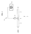
FIG. 1] Fig. 1 is a diagram showing, in outline, the configuration of a flow rate controller according to an embodiment of the present invention. - [
FIG. 2] Fig. 2 is a longitudinal sectional view of a case accommodating a valve and a pulse motor shown inFig. 1 . - [
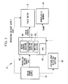
FIG. 3] Fig. 3 is a block diagram showing, in outline, the configuration of a motor control unit according to the embodiment of the present invention. - [
FIG. 4] Fig. 4 is a graph showing the progression of power supply voltage and microcomputer voltage in the case where power supplied from a drive power supply is interrupted. - [
FIG. 5] Fig. 5 is a diagram showing an example of a power system of the motor control unit shown inFig. 3 . - [
FIG. 6] Fig. 6 is a circuit diagram showing an example of the internal configuration of a voltage-drop detecting section shown inFig. 3 . - [
FIG. 7] Fig. 7 is a circuit diagram showing another example of the internal configuration of the voltage-drop detecting section shown inFig. 3 . -
- 1:
- flow rate controller
- 2:
- fluid channel
- 3:
- valve
- 4:
- valve control apparatus
- 5:
- pulse motor
- 6:
- motor control unit
- 14:
- diaphragm needle
- 15a:
- rotating shaft
- 16:
- coupling
- 17:
- slider
- 21:
- spring
- 23:
- case
- 29:
- cable
- 43:
- port
- 61:
- drive power supply
- 62:
- microcomputer
- 63:
- A/D converter
- 64:
- nonvolatile memory
- 65:
- voltage-drop detecting section
- 66:
- motor control section
- 67:
- counting section
- 68:
- writing section
- 74:
- capacitor
- 91:
- Zener diode set
- An embodiment in which a motor control unit of the present invention is applied to a flow rate controller will now be described.
-
Fig. 1 is a diagram showing, in outline, the configuration of the flow rate controller according to this embodiment. Thisflow rate controller 1 includes, as main components, a valve 3 provided in afluid channel 2 to control the flow rate of a fluid flowing through thefluid channel 2 and a valve control apparatus 4 for driving the valve 3. The valve control apparatus 4 includes apulse motor 5 coupled to the valve 3 and amotor control unit 6 for controlling thepulse motor 5.
Fig. 2 is a diagram showing, in outline, the configuration of the valve 3 shown inFig. 1 . The valve 3 inFig. 1 includes adiaphragm needle 14, for example, as a valve element. Thisdiaphragm needle 14 is integrated with thepulse motor 5 and is accommodated in acase 23. - The
pulse motor 5 in thecase 23 is connected to themotor control unit 6 through acable 29. The rotation angle is controlled based on drive signals supplied through thecable 29.
Arotating shaft 15a of thepulse motor 5 is coupled to acoupling 16. Thecoupling 16 is coupled to aslider 17 via aspring 21. Theslider 17 is coupled to thediaphragm needle 14. Thediaphragm needle 14 is disposed in aport 43 formed in thefluid channel 2.
The flow rate of a fluid flowing through thefluid channel 2 is adjusted depending on the gap area between thediaphragm needle 14 and the bottom surface of theport 43. - Next, the operation of the valve 10 will be briefly described.
Suppose, for example, that no fluid flows through theport 43 with thediaphragm needle 14 in contact with the bottom surface of theport 43; that is, the valve 3 is completely closed. If themotor control unit 6, to be described later, supplies thepulse motor 5 with a drive signal that causes it to be driven in such a direction as to open the valve, therotating shaft 15a rotates in such a direction as to lift the diaphragm needle 14 (for example, clockwise as viewed from above inFig. 1 ) based on the drive signal. - With this rotation, the
coupling 16 coupled to therotating shaft 15a rotates in the same direction, and accordingly theslider 17 coupled to thecoupling 16 moves upward along the motor shaft. As theslider 17 moves upward, it lifts thediaphragm needle 14 coupled to theslider 17 to form a gap between thediaphragm needle 14 and the bottom surface of theport 43, so that the valve 3 is opened.
This allows a fluid to flow into theport 43. After the fluid fills theport 43, it flows sequentially into afluid outlet portion 42 and then flows out of thefluid outlet portion 42. - In this valve-opening operation, the gap area between the
diaphragm needle 14 and the bottom surface of theport 43 is adjusted depending on the number of drive pulses applied to thepulse motor 5. Specifically, themotor control unit 6 increases the gap area to increase the flow rate of the fluid by increasing the number of pulses applied to thepulse motor 5. To reduce the flow rate of the fluid, or to close the valve, on the other hand, closing-direction drive pulses are applied to thepulse motor 5 to rotate therotating shaft 15a of thepulse motor 5 in the direction opposite the above direction (for example, counterclockwise as viewed from above inFig. 1 ), thus gradually reducing the gap area between thediaphragm needle 14 and the bottom surface of theport 43.
The flow rate can be eventually reduced to zero by completely closing thediaphragm needle 14. - Next, the
motor control unit 6 will be described.
Fig. 3 is a block diagram showing, in outline, the configuration of themotor control unit 6 according to this embodiment.
Themotor control unit 6 includes amicrocomputer 62 that operates with an operating voltage of 5 V supplied from adrive power supply 61, an A/D converter 63 that operates with an operating voltage of 6 V supplied from thedrive power supply 61, anonvolatile memory 64 such as a ROM, and a voltage-drop detecting section 65 for detecting a voltage drop of thedrive power supply 61.
Themicrocomputer 62 includes amotor control section 66 for applying drive pulses as drive signals to thepulse motor 5, acounting section 67 for counting the number of drive pulses applied to thepulse motor 5, and awriting section 68 for writing the count from thecounting section 67 in thenonvolatile memory 64 if the voltage-drop detecting section 65 detects a voltage drop. - In the
motor control unit 6 thus configured, during the driving of the valve 3 (seeFig. 1 ), themotor control section 66 incorporated in themicrocomputer 62 applies drive pulses corresponding to a target open/close value of the valve 3 to thepulse motor 5, thereby controlling the rotation angle of thepulse motor 5 to a desired angle. As a result, thediaphragm needle 14 is lifted or lowered, as described above, thus controlling the flow rate of the fluid flowing through thefluid channel 2. At the same time, thecounting section 67 counts the number of drive pulses applied to thepulse motor 5. - If the power supplied from the
drive power supply 61 is interrupted for any reason during the valve control, the voltage-drop detecting section 65 detects the voltage drop of thedrive power supply 61 and notifies themicrocomputer 62. In response to the notification of the voltage drop, thewriting section 68 of themicrocomputer 62 reads a count from thecounting section 67 and writes it in thenonvolatile memory 64. This allows the position of thepulse motor 5 to be stored in thenonvolatile memory 64 if thepulse motor 5 stops due to a power interruption during the driving, so that the position of thepulse motor 5 can readily be identified upon restarting. - If the power supplied from the
drive power supply 61 is interrupted for any reason, as described above, the voltage supplied from thedrive power supply 61 to the voltage-drop detecting section 65 (herein referred to as the "power supply voltage"), as indicated by the solid line inFig. 4 , drops gradually from time t1 and reaches zero at time t5. In contrast, the microcomputer voltage supplied to themicrocomputer 62, as indicated by the broken line inFig. 4 , remains at 5 V for a predetermined period of time after the power supply voltage starts dropping at time t1, and drops gradually from time t3 and reaches zero at time t5.
Thus, the start of the drop in power supply voltage and the start of the drop in microcomputer voltage are separated by a time difference (for example, about 130 ms) during which thewriting section 68 writes the count in thenonvolatile memory 64. - More specifically, the period of time during which the
writing section 68 can write in thenonvolatile memory 64 is a drive termination period from voltage-drop detection (at time t2 inFig. 4 ), at which the drop in power supply voltage is detected due to the power supply voltage falling below a reference voltage V1 used as a reference by the voltage-drop detecting section 65, to drive termination (at time t4 inFig. 4 ), at which the driving of themicrocomputer 62 stops due to the microcomputer voltage falling below the minimum operating voltage V2 of the microcomputer.
The drive termination period varies from device to device because it depends on, for example, the circuit configuration of themotor control unit 6; in some cases, there might be a possibility that the operation of themicrocomputer 62 cannot be sustained until thewriting section 68 finishes writing the count. - Hence, the
motor control unit 6 according to this embodiment includes a period-adjusting component (period-adjusting section) for extending the drive termination period to a predetermined period of time or more. The predetermined period of time must at least be set to be longer than the writing period during which thewriting section 68 built into themicrocomputer 62 writes the count in thenonvolatile memory 64. -
Fig. 5 shows an example of the power system of themotor control unit 6. InFig. 5 , a voltage of 24 V output from thedrive power supply 61 is input to a DC/DC converter 70 for the microcomputer. The DC/DC converter 70 lowers the voltage to a stable voltage of 5 V before supplying it to themicrocomputer 62. The voltage output from thedrive power supply 61 is also input to apower converter 71 for the A/D converter. Thepower converter 71 lowers the voltage to a stable voltage of 6 V before supplying it to the A/D converter 63. The voltage output from thedrive power supply 61 is also input directly to the voltage-drop detecting section 65. - In this case, a capacitor (period-adjusting section) 74 is provided between the DC/
DC converter 70 for the microcomputer and themicrocomputer 62. This allows the time at which the microcomputer voltage drops, namely, time t3, as shown inFig. 4 , to be delayed. As a result, the drive termination period can be extended. The time at which the microcomputer voltage drops can be adjusted by adjusting the capacitance of thecapacitor 74. - To extend the above drive termination period, additionally, the voltage-
drop detecting section 65 has the following configuration.
Fig. 6 is a diagram showing an example of the circuit configuration of the voltage-drop detecting section 65. InFig. 6 , aninput terminal 90 through which the power supply voltage of thedrive power supply 61 is input is connected to ground through a series-connected Zener diode set 91 and a resistor divider R2. The Zener diode set 91 includes a 9 V Zener diode D1 and a 10 V Zener diode D3 that are connected in series. A node between the Zener diode set 91 and the resistor R2 is connected to, for example, a comparator (not shown) through a resistor R1. - According to the configuration of the voltage-
drop detecting section 65, a power supply voltage of 24 V input from the drive power supply to theinput terminal 90 is divided by the Zener diode set (period-adjusting section) 91 and the resistor R2 and is input to the comparator (not shown) through the resistor R1 (the voltage input to the comparator will be hereinafter referred to as the "detection voltage"). The detection voltage input to one terminal of the comparator is compared with a reference voltage input to the other terminal of the comparator, and the comparison result is output to themicrocomputer 62. If the detection voltage falls below the reference voltage after a drop in the power supply voltage input to theinput terminal 90, the output of the comparator is reversed, so that themicrocomputer 62 can be notified of the voltage drop. - In the voltage-
drop detecting section 65, in this case, the power supply voltage input to theinput terminal 90 is divided by the Zener diode set 91 and the resistor R2. Thus, the use of the Zener diode set 91, which totals 19 V (= 9 V + 10 V), allows the voltage obtained by subtracting 19 V from the power supply voltage to be constantly input to the comparator as the detection voltage.
Accordingly, for example, a drop in power supply voltage can be detected more quickly than in the case where the Zener diode set 91 is replaced with resistors R5 and R6, as shown inFig. 7 . - In the
motor control unit 6 according to this embodiment, as described above, if the voltage supplied from thedrive power supply 61 is interrupted, this state is quickly detected, and the current count is stored in thenonvolatile memory 64. The count is read from thenonvolatile memory 64 upon restarting, so that the position of thepulse motor 5, in other words, the position of the valve 3, can readily be identified. This eliminates the need for conventional origin retrieval control, thus reducing the time to shift from activation to normal operation. - In addition, the pulse motor can always be driven within its range of motion because the position of the
pulse motor 5 can be identified without moving it. This avoids biting of a screw part. Furthermore, the size of the apparatus can be reduced because the need for a position-detecting sensor such as a rotary encoder can be eliminated. - Upon activation of the flow rate controller according to this embodiment, for example, it may be shifted to normal drive control after the
motor control unit 6 returns the valve 3 to the origin by reading the count written in thenonvolatile memory 64 and returning thepulse motor 5 to the original position based on the count. - The embodiment of the present invention has been described in detail with reference to the drawings, although its specific configuration is not limited to the above embodiment; design changes, for example, are also encompassed without departing from the spirit of the present invention.
Although themotor control unit 6 is used for control of the valve 3 of theflow rate controller 1 in the embodiment described above, it can also be used for position control of driven parts other than valves.
Claims (6)
- A valve control apparatus for driving a valve for controlling the flow rate of a fluid flowing through a fluid channel, comprising:a stepping motor coupled to the valve; anda motor control unit for controlling the stepping motor;wherein the motor control unit comprises:a motor control section for applying drive pulses to the pulse motor;a counting section for counting the number of drive pulses applied to the pulse motor;a voltage-drop detecting section for detecting a voltage drop of a drive power supply for the motor control section; anda writing section for writing a count from the counting section in a nonvolatile memory if the voltage-drop detecting section detects the voltage drop.
- The valve control apparatus according to Claim 1, further comprising a period-adjusting section for extending a drive termination period to a predetermined period of time or more, the drive termination period being from voltage-drop detection at which the voltage-drop detecting section detects the voltage drop to drive termination at which the driving of the motor control section stops.
- The valve control apparatus according to Claim 1, wherein the motor control section executes return-to-origin control for returning the valve to an origin at the start of driving of the pulse motor by reading the count written in the nonvolatile memory and driving the pulse motor based on the count.
- A flow rate controller comprising:a valve for controlling the flow rate of a fluid flowing through a fluid channel; andthe valve control apparatus according to Claim 1.
- A motor control unit comprising:a motor control section for applying drive pulses to the pulse motor;a counting section for counting the number of drive pulses applied to the pulse motor;a voltage-drop detecting section for detecting a voltage drop of a drive power supply for the motor control section; anda writing section for writing a count from the counting section in a nonvolatile memory if the voltage-drop detecting section detects the voltage drop.
- A pulse motor apparatus comprising:a pulse motor; andthe motor control unit according to Claim 5, which controls the pulse motor.
Applications Claiming Priority (2)
| Application Number | Priority Date | Filing Date | Title |
|---|---|---|---|
| JP2006128922A JP5111780B2 (en) | 2006-05-08 | 2006-05-08 | Valve control device and flow controller |
| PCT/JP2007/059487 WO2007129697A1 (en) | 2006-05-08 | 2007-05-08 | Valve control apparatus and flow volume controller |
Publications (2)
| Publication Number | Publication Date |
|---|---|
| EP2017513A1 true EP2017513A1 (en) | 2009-01-21 |
| EP2017513A4 EP2017513A4 (en) | 2017-12-06 |
Family
ID=38667805
Family Applications (1)
| Application Number | Title | Priority Date | Filing Date |
|---|---|---|---|
| EP07742922.3A Pending EP2017513A4 (en) | 2006-05-08 | 2007-05-08 | Valve control apparatus and flow volume controller |
Country Status (5)
| Country | Link |
|---|---|
| US (1) | US8172199B2 (en) |
| EP (1) | EP2017513A4 (en) |
| JP (1) | JP5111780B2 (en) |
| KR (1) | KR101296508B1 (en) |
| WO (1) | WO2007129697A1 (en) |
Cited By (5)
| Publication number | Priority date | Publication date | Assignee | Title |
|---|---|---|---|---|
| CN102052500A (en) * | 2009-11-09 | 2011-05-11 | 项晓明 | Noninvasive type intelligent valve electric device |
| CN102359638A (en) * | 2011-08-13 | 2012-02-22 | 黄山良业阀门有限公司 | Valve electric device for field bus and wireless control |
| CN102840371A (en) * | 2012-09-04 | 2012-12-26 | 绍兴文理学院 | Remote electric valve control system of CDMA (code division multiple access) network |
| CN104864151A (en) * | 2015-05-19 | 2015-08-26 | 西安恒隆电气有限公司 | Internet of Things balance valve and control method thereof |
| EP2216700B1 (en) * | 2009-02-10 | 2017-07-12 | Surpass Industry Co., Ltd. | Flow rate controller |
Families Citing this family (12)
| Publication number | Priority date | Publication date | Assignee | Title |
|---|---|---|---|---|
| DE102009014745A1 (en) * | 2008-03-26 | 2009-11-05 | Fisher & Paykel Appliances Ltd., East Tamaki | Gas cooker device |
| JP5386881B2 (en) * | 2008-08-07 | 2014-01-15 | セイコーエプソン株式会社 | Label paper cueing control method and label printer |
| KR101043742B1 (en) * | 2009-06-04 | 2011-06-22 | 한길용 | Stepping Motor Controlling Apparatus |
| KR101647649B1 (en) * | 2009-06-08 | 2016-08-11 | 코웨이 주식회사 | Control and method for controlling stepping motor driving disk member |
| ES2386517T3 (en) * | 2009-10-16 | 2012-08-22 | Diener Precision Pumps Ltd. | Electronic adapter to control a bistable valve |
| JP2011220451A (en) * | 2010-04-09 | 2011-11-04 | Saginomiya Seisakusho Inc | Pulse driving device of motor-operated valve and control system of motor-operated valve having the same |
| CN106975117A (en) | 2011-09-21 | 2017-07-25 | 拜耳医药保健有限责任公司 | Continuous multiple fluid pump device, driving and actuating system and method |
| CN107427411B (en) | 2015-01-09 | 2021-04-02 | 拜耳医药保健有限公司 | Multi-fluid delivery system with multi-use disposable set and features thereof |
| KR101706602B1 (en) * | 2015-12-01 | 2017-02-15 | 주식회사 큐플러스 | Apparatus of controlling for flow regulating valve by stepping control |
| JP6764316B2 (en) * | 2016-10-31 | 2020-09-30 | 株式会社不二工機 | Solenoid valve control device and motorized valve device equipped with it |
| JP6945882B2 (en) * | 2017-11-20 | 2021-10-06 | 株式会社不二工機 | Electric valve control device and electric valve device equipped with it |
| JP6757088B2 (en) * | 2019-10-07 | 2020-09-16 | 株式会社不二工機 | Solenoid valve control device and motorized valve device equipped with it |
Family Cites Families (20)
| Publication number | Priority date | Publication date | Assignee | Title |
|---|---|---|---|---|
| JPS6154502A (en) * | 1984-08-24 | 1986-03-18 | Mitsubishi Electric Corp | Numerical controller |
| DE3484654D1 (en) * | 1984-10-11 | 1991-07-04 | Matsushita Electric Ind Co Ltd | DEVICE FOR CLOSING GAS. |
| US4694861A (en) * | 1986-12-22 | 1987-09-22 | Beckman Instruments, Inc. | Rotary pinch valve |
| US5240022A (en) * | 1991-10-03 | 1993-08-31 | Franklin Robert C | Automatic shutoff valve |
| JP3283081B2 (en) * | 1992-12-18 | 2002-05-20 | 株式会社東海理化電機製作所 | Power window control device |
| JPH07322693A (en) * | 1994-05-24 | 1995-12-08 | Canon Inc | Stepping-motor driving apparatus and recorder using stepping-motor driving means |
| CN1244932A (en) * | 1996-12-12 | 2000-02-16 | 美国标准公司 | Valve system for servo control of fluid flows |
| US6186471B1 (en) * | 1998-05-15 | 2001-02-13 | Taco, Inc. | Electronic motorized zone valve |
| EP1152190A1 (en) * | 1998-11-24 | 2001-11-07 | Matsushita Electric Industrial Co., Ltd. | Gas flow rate controller and gas appliance using the same |
| JP4028291B2 (en) * | 2002-05-16 | 2007-12-26 | 株式会社鷺宮製作所 | Motorized valve drive device and refrigeration cycle device |
| JP3654645B2 (en) * | 2002-05-21 | 2005-06-02 | 三菱電機株式会社 | Abnormality detection device for motor drive system |
| JP4158086B2 (en) | 2002-05-29 | 2008-10-01 | 日本パルスモーター株式会社 | Positioning operation device and its origin setting method |
| JP3876847B2 (en) * | 2003-03-26 | 2007-02-07 | 株式会社デンソー | Electric actuator system |
| JP4311981B2 (en) | 2003-05-20 | 2009-08-12 | 東京計装株式会社 | Valve control device and origin search method thereof |
| JP4196345B2 (en) * | 2004-02-18 | 2008-12-17 | 株式会社デンソー | Valve open / close control device |
| JP4160522B2 (en) * | 2004-03-11 | 2008-10-01 | リンナイ株式会社 | Electric valve device |
| US7789370B2 (en) * | 2004-04-23 | 2010-09-07 | Vetco Gray Scandanavia As | Actuator system |
| US20060238039A1 (en) * | 2005-04-06 | 2006-10-26 | Parker-Hannifin Corporation | Step motor valve assembly with fail-safe feature |
| US7556238B2 (en) * | 2005-07-20 | 2009-07-07 | Fisher Controls International Llc | Emergency shutdown system |
| US7377479B1 (en) * | 2006-11-28 | 2008-05-27 | Shui-Ching Chen | Position restoring apparatus for an open and close device |
-
2006
- 2006-05-08 JP JP2006128922A patent/JP5111780B2/en active Active
-
2007
- 2007-05-08 WO PCT/JP2007/059487 patent/WO2007129697A1/en active Application Filing
- 2007-05-08 US US12/226,367 patent/US8172199B2/en active Active
- 2007-05-08 EP EP07742922.3A patent/EP2017513A4/en active Pending
- 2007-05-08 KR KR1020087025745A patent/KR101296508B1/en active IP Right Grant
Non-Patent Citations (1)
| Title |
|---|
| See references of WO2007129697A1 * |
Cited By (6)
| Publication number | Priority date | Publication date | Assignee | Title |
|---|---|---|---|---|
| EP2216700B1 (en) * | 2009-02-10 | 2017-07-12 | Surpass Industry Co., Ltd. | Flow rate controller |
| CN102052500A (en) * | 2009-11-09 | 2011-05-11 | 项晓明 | Noninvasive type intelligent valve electric device |
| CN102359638A (en) * | 2011-08-13 | 2012-02-22 | 黄山良业阀门有限公司 | Valve electric device for field bus and wireless control |
| CN102840371A (en) * | 2012-09-04 | 2012-12-26 | 绍兴文理学院 | Remote electric valve control system of CDMA (code division multiple access) network |
| CN102840371B (en) * | 2012-09-04 | 2014-06-11 | 绍兴文理学院 | Remote electric valve control system of CDMA (code division multiple access) network |
| CN104864151A (en) * | 2015-05-19 | 2015-08-26 | 西安恒隆电气有限公司 | Internet of Things balance valve and control method thereof |
Also Published As
| Publication number | Publication date |
|---|---|
| US8172199B2 (en) | 2012-05-08 |
| EP2017513A4 (en) | 2017-12-06 |
| KR101296508B1 (en) | 2013-08-13 |
| WO2007129697A1 (en) | 2007-11-15 |
| US20090230339A1 (en) | 2009-09-17 |
| JP5111780B2 (en) | 2013-01-09 |
| KR20090013173A (en) | 2009-02-04 |
| JP2007298158A (en) | 2007-11-15 |
Similar Documents
| Publication | Publication Date | Title |
|---|---|---|
| US8172199B2 (en) | Valve control apparatus and flow rate controller | |
| KR101115350B1 (en) | Pressure control valve driving circuit for pressure-type flow rate control apparatus with flow rate self-diagnosis function | |
| EP1433921B1 (en) | Shutter mechanism including stepping motor | |
| US7758015B2 (en) | Solenoid-operated valve controller | |
| EP3080621A1 (en) | Method and system for diagnose of a solenoid valve | |
| AU2019331398B2 (en) | Improved valve position control | |
| KR100414477B1 (en) | Power window apparatus | |
| JPH0522983B2 (en) | ||
| US20090132114A1 (en) | Control Device and Adjusting Mechanism of a Motor Vehicle | |
| JPH024432B2 (en) | ||
| JP4775693B2 (en) | 2-wire transmitter | |
| EP0585140A2 (en) | Motor drive circuit | |
| JP3634459B2 (en) | Solenoid valve drive control method | |
| US10437201B1 (en) | Compensated actuator system | |
| CA1297526C (en) | Solenoid response detector | |
| US6836088B2 (en) | Motor driving circuit | |
| JP5796536B2 (en) | Electronic circuit | |
| US5214544A (en) | Apparatus for generating a track zero signal in a floppy disc driver without an optical track zero sensor | |
| JP2001015334A (en) | Actuation detecting circuit for latching solenoid | |
| US20100131967A1 (en) | Storage medium changer | |
| JPH05284770A (en) | Drive controller for motor | |
| WO2003054649A1 (en) | A method of controlling an adjusting device, and the corresponding device | |
| JP2000018426A (en) | Cutoff valve driving and controlling device | |
| JP2000188895A (en) | Motor controller | |
| KR19980027928A (en) | How to Detect Tray Movement on Compact Disc Drives |
Legal Events
| Date | Code | Title | Description |
|---|---|---|---|
| PUAI | Public reference made under article 153(3) epc to a published international application that has entered the european phase |
Free format text: ORIGINAL CODE: 0009012 |
|
| 17P | Request for examination filed |
Effective date: 20081020 |
|
| AK | Designated contracting states |
Kind code of ref document: A1 Designated state(s): AT BE BG CH CY CZ DE DK EE ES FI FR GB GR HU IE IS IT LI LT LU LV MC MT NL PL PT RO SE SI SK TR |
|
| AX | Request for extension of the european patent |
Extension state: AL BA HR MK RS |
|
| RBV | Designated contracting states (corrected) |
Designated state(s): DE |
|
| DAX | Request for extension of the european patent (deleted) | ||
| RIC1 | Information provided on ipc code assigned before grant |
Ipc: H02P 8/42 20060101ALI20171025BHEP Ipc: F16K 31/04 20060101AFI20171025BHEP Ipc: F16K 37/00 20060101ALI20171025BHEP Ipc: G05D 7/06 20060101ALI20171025BHEP |
|
| RA4 | Supplementary search report drawn up and despatched (corrected) |
Effective date: 20171106 |
|
| STAA | Information on the status of an ep patent application or granted ep patent |
Free format text: STATUS: EXAMINATION IS IN PROGRESS |
|
| 17Q | First examination report despatched |
Effective date: 20181204 |
|
| STAA | Information on the status of an ep patent application or granted ep patent |
Free format text: STATUS: EXAMINATION IS IN PROGRESS |
|
| STAA | Information on the status of an ep patent application or granted ep patent |
Free format text: STATUS: EXAMINATION IS IN PROGRESS |
|
| REG | Reference to a national code |
Ref country code: DE Ref legal event code: R079 Free format text: PREVIOUS MAIN CLASS: F16K0031040000 Ipc: G05D0007060000 |
|
| GRAP | Despatch of communication of intention to grant a patent |
Free format text: ORIGINAL CODE: EPIDOSNIGR1 |
|
| STAA | Information on the status of an ep patent application or granted ep patent |
Free format text: STATUS: GRANT OF PATENT IS INTENDED |
|
| RIC1 | Information provided on ipc code assigned before grant |
Ipc: F16K 37/00 20060101ALI20231127BHEP Ipc: H02P 8/42 20060101ALI20231127BHEP Ipc: F16K 31/04 20060101ALI20231127BHEP Ipc: H02P 8/26 20060101ALI20231127BHEP Ipc: G05D 7/06 20060101AFI20231127BHEP |
|
| INTG | Intention to grant announced |
Effective date: 20231213 |
|
| GRAS | Grant fee paid |
Free format text: ORIGINAL CODE: EPIDOSNIGR3 |