EP2017207A2 - Système de pinces pour une machine d'impression de feuilles - Google Patents
Système de pinces pour une machine d'impression de feuilles Download PDFInfo
- Publication number
- EP2017207A2 EP2017207A2 EP08159683A EP08159683A EP2017207A2 EP 2017207 A2 EP2017207 A2 EP 2017207A2 EP 08159683 A EP08159683 A EP 08159683A EP 08159683 A EP08159683 A EP 08159683A EP 2017207 A2 EP2017207 A2 EP 2017207A2
- Authority
- EP
- European Patent Office
- Prior art keywords
- gripper
- sheet
- gripper system
- transverse edge
- transverse
- Prior art date
- Legal status (The legal status is an assumption and is not a legal conclusion. Google has not performed a legal analysis and makes no representation as to the accuracy of the status listed.)
- Withdrawn
Links
- 238000007639 printing Methods 0.000 title claims abstract description 16
- 239000000758 substrate Substances 0.000 claims abstract description 7
- 239000000463 material Substances 0.000 claims description 9
- 239000011324 bead Substances 0.000 claims description 6
- 238000006073 displacement reaction Methods 0.000 claims description 4
- 238000003780 insertion Methods 0.000 claims description 2
- 230000037431 insertion Effects 0.000 claims description 2
- 230000006698 induction Effects 0.000 claims 1
- 238000001035 drying Methods 0.000 description 4
- 238000000227 grinding Methods 0.000 description 4
- 230000000694 effects Effects 0.000 description 3
- 230000004913 activation Effects 0.000 description 1
- 238000010276 construction Methods 0.000 description 1
- 239000013078 crystal Substances 0.000 description 1
- 238000004146 energy storage Methods 0.000 description 1
- 238000005516 engineering process Methods 0.000 description 1
- 230000001939 inductive effect Effects 0.000 description 1
- 230000007246 mechanism Effects 0.000 description 1
- 238000007645 offset printing Methods 0.000 description 1
- 230000037303 wrinkles Effects 0.000 description 1
Images
Classifications
-
- B—PERFORMING OPERATIONS; TRANSPORTING
- B65—CONVEYING; PACKING; STORING; HANDLING THIN OR FILAMENTARY MATERIAL
- B65H—HANDLING THIN OR FILAMENTARY MATERIAL, e.g. SHEETS, WEBS, CABLES
- B65H29/00—Delivering or advancing articles from machines; Advancing articles to or into piles
- B65H29/02—Delivering or advancing articles from machines; Advancing articles to or into piles by mechanical grippers engaging the leading edge only of the articles
- B65H29/04—Delivering or advancing articles from machines; Advancing articles to or into piles by mechanical grippers engaging the leading edge only of the articles the grippers being carried by endless chains or bands
- B65H29/045—Details of grippers
-
- B—PERFORMING OPERATIONS; TRANSPORTING
- B41—PRINTING; LINING MACHINES; TYPEWRITERS; STAMPS
- B41F—PRINTING MACHINES OR PRESSES
- B41F21/00—Devices for conveying sheets through printing apparatus or machines
- B41F21/08—Combinations of endless conveyors and grippers
-
- B—PERFORMING OPERATIONS; TRANSPORTING
- B65—CONVEYING; PACKING; STORING; HANDLING THIN OR FILAMENTARY MATERIAL
- B65H—HANDLING THIN OR FILAMENTARY MATERIAL, e.g. SHEETS, WEBS, CABLES
- B65H29/00—Delivering or advancing articles from machines; Advancing articles to or into piles
- B65H29/02—Delivering or advancing articles from machines; Advancing articles to or into piles by mechanical grippers engaging the leading edge only of the articles
- B65H29/04—Delivering or advancing articles from machines; Advancing articles to or into piles by mechanical grippers engaging the leading edge only of the articles the grippers being carried by endless chains or bands
- B65H29/041—Delivering or advancing articles from machines; Advancing articles to or into piles by mechanical grippers engaging the leading edge only of the articles the grippers being carried by endless chains or bands and introducing into a pile
-
- B—PERFORMING OPERATIONS; TRANSPORTING
- B65—CONVEYING; PACKING; STORING; HANDLING THIN OR FILAMENTARY MATERIAL
- B65H—HANDLING THIN OR FILAMENTARY MATERIAL, e.g. SHEETS, WEBS, CABLES
- B65H9/00—Registering, e.g. orientating, articles; Devices therefor
- B65H9/10—Pusher and like movable registers; Pusher or gripper devices which move articles into registered position
- B65H9/101—Pusher and like movable registers; Pusher or gripper devices which move articles into registered position acting on the edge of the article
-
- B—PERFORMING OPERATIONS; TRANSPORTING
- B65—CONVEYING; PACKING; STORING; HANDLING THIN OR FILAMENTARY MATERIAL
- B65H—HANDLING THIN OR FILAMENTARY MATERIAL, e.g. SHEETS, WEBS, CABLES
- B65H2301/00—Handling processes for sheets or webs
- B65H2301/50—Auxiliary process performed during handling process
- B65H2301/51—Modifying a characteristic of handled material
- B65H2301/512—Changing form of handled material
- B65H2301/5121—Bending, buckling, curling, bringing a curvature
-
- B—PERFORMING OPERATIONS; TRANSPORTING
- B65—CONVEYING; PACKING; STORING; HANDLING THIN OR FILAMENTARY MATERIAL
- B65H—HANDLING THIN OR FILAMENTARY MATERIAL, e.g. SHEETS, WEBS, CABLES
- B65H2301/00—Handling processes for sheets or webs
- B65H2301/50—Auxiliary process performed during handling process
- B65H2301/51—Modifying a characteristic of handled material
- B65H2301/512—Changing form of handled material
- B65H2301/5122—Corrugating; Stiffening
-
- B—PERFORMING OPERATIONS; TRANSPORTING
- B65—CONVEYING; PACKING; STORING; HANDLING THIN OR FILAMENTARY MATERIAL
- B65H—HANDLING THIN OR FILAMENTARY MATERIAL, e.g. SHEETS, WEBS, CABLES
- B65H2405/00—Parts for holding the handled material
- B65H2405/50—Gripping means
- B65H2405/57—Details of the gripping parts
-
- B—PERFORMING OPERATIONS; TRANSPORTING
- B65—CONVEYING; PACKING; STORING; HANDLING THIN OR FILAMENTARY MATERIAL
- B65H—HANDLING THIN OR FILAMENTARY MATERIAL, e.g. SHEETS, WEBS, CABLES
- B65H2511/00—Dimensions; Position; Numbers; Identification; Occurrences
- B65H2511/10—Size; Dimensions
- B65H2511/16—Irregularities, e.g. protuberances
-
- B—PERFORMING OPERATIONS; TRANSPORTING
- B65—CONVEYING; PACKING; STORING; HANDLING THIN OR FILAMENTARY MATERIAL
- B65H—HANDLING THIN OR FILAMENTARY MATERIAL, e.g. SHEETS, WEBS, CABLES
- B65H2555/00—Actuating means
- B65H2555/10—Actuating means linear
- B65H2555/14—Actuating means linear piezoelectric
Definitions
- the invention relates to a gripper system for a sheet-fed printing machine for handling the transfer of an arcuate printing material.
- the invention is directed to a gripper system which is connected to a continuously running as a chain or timing belt and rotating traction means and by which the substrate is transferred in a downstream of the printing units area by a drying and / or powdering station in the area of the sheet storage ,
- Out DE 203 13 394 U1 is a boom for a sheet-fed press known which comprises a closed gripper chain device with a plurality of equidistantly connected thereto and rotating with the gripper chain device gripper systems.
- a tapped from the last printing unit sheet can be passed through a drying station and a powdering station.
- the path of the gripper chain device is determined by a gripper chain guide which typically comprises a plurality of deflection zones. The distance between these deflection zones can be dimensioned so large that the guided along the gripper system path arc is fully extended in phases.
- the invention has for its object to provide solutions by which it is possible, in particular during the transport of a gripping systems gripped sheet over longer, rectilinear gripper track areas to achieve improvements in sheet travel behavior, so that this stable example, led by a drying and / or powdering station can be.
- this curvature can form a simple curvature that bulges upward or downward transversely to the main plane of the arch. It is also possible to impose multiple waves on the bow, so that the bow is stiffened by several "longitudinal beads".
- the tensioning stroke in this case in the area of the clamped curved transverse edge is preferably in the range of less than 10 to 15 millimeters.
- the setting of said deviation of the clamped arc transverse edge of the transverse line is only temporary, so that the sheet stiffening according to the invention is brought about only in certain, typically relatively straight stretched Bogenlaufpfadabroughen.
- the inventively brought about by slight adjustment of the positions of the gripper portions chucking the transverse edge is canceled again, so that the bow wrinkle free over the corresponding groove of the sheet smoother and thereby dive into it.
- the gripper system is designed so that the position of the respective gripper opening portion relative to the gripper carriage carrying these is variable by the inventively provided adjusting means.
- the gripper fingers may be designed to be elastic so that they tolerate the change in position of the gripper opening portion.
- the gripper fingers are so involved in the inventive mime that the change in the position of the gripper opening portion without undue changes in the sheet clamping force in the gripper fingers takes place.
- the adjusting means provided according to the invention for displacing the gripper opening section can be realized in particular with the inclusion of actuators, which as such are integrated in the gripper system and run with it.
- the actuators may be designed as piezo actuators, in which the required travel is brought about by volume change of crystals by applying voltage.
- the actuation of the adjusting means is preferably carried out such that the sheet transverse edge receives at least one transversely directed to the gripper carriage track bulge.
- This bulge can be done so that the arc bulges either up or down. It is also possible to control a plurality of grippers of the gripper system in such a way that a web or bead structure is impressed on the printing material gripped by them.
- the proposed according to the invention for curving the Bogenquerkante displacement of Greiferaufschlagabitese each other is preferably timed or matched with respect to certain gripper track sections, so that the stiffening takes place only in certain areas, especially a largely rectilinear stretched sheet travel path. It is possible to make use of the activation of the actuators proposed according to the invention only then, if the sheet travel behavior is assessed as unsatisfactory, especially if fluttering of the printing material is detected by sensors integrated in the corresponding machine.
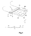
- the in FIG. 1 shown gripper carriage 1 is involved in a conventional manner in a here shown only gripper chain system 2 and serves in particular the transfer of a printing sheet 3 from the output area of the last printing unit of a printing press and the shipment of the sheet to a sheet storage area.
- the gripper carriage 1 is provided with a plurality of spaced-apart grippers 4.
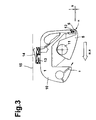
- FIG. 3 shows a gripper finger 5 and a gripper opening portion 6, wherein the gripper fingers 5 can be brought into an open state, in which either a Jerusalem motifder sheet introduced into the gripper system, or a just be deposited sheet can be released.
- gripper fingers 5 cooperate in each case with the gripper impact section 6, wherein this gripper opening section 6 provides a seating surface K onto which the gripped printed sheet is clamped by the gripper finger 5.
- the gripper system shown here is characterized in that it is equipped with adjusting means by which a defined by the gripper system Bogenquerkanten Scheme Q a defined deviation from a the edge-side corners P1, P2 of the sheet 3 connecting transverse line g can be awarded.
- the control of the individual gripper 4 of the gripper system 1 is preferably such that the recognizable, "wavy" Aufgriff the sheet B and thus caused by Lekssicken Struktur stiffening only temporarily, i. takes place for a specific section of the sheet career. Otherwise, the printed sheet B is picked up substantially straight, so that it can be curved wrinkle-free outside of the stiffening region about a transverse to the sheet running direction BLR axis X.
- the clamping of the transverse edge Q of the sheet B is carried out such that on the signature B two upwardly bulging longitudinal beads W1, W2, and an intermediate, down bulging longitudinal bead W3 results.
- This concept becomes a special one achieved effective temporary L jossaussteifung the press sheet B in a specific Bogenbahnabêt a boom.
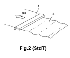
- FIG. 2 is a conventional gripper system shown by which the sheet B is taken straight in the region of its front transverse edge Q.
- the sheet B stretched in this way can, as indicated here, form corrugations running transversely to the direction of sheet travel BLR and thereby flutter.
- FIG. 3 a preferred construction of a gripper system according to the invention is shown.
- This gripper system comprises a gripper carriage spar 10, here made of an extruded profile material, on which, in the longitudinal direction, a plurality of gripper fingers 5 are pivotably mounted on a gripper shaft 11.
- These gripper fingers 5 together with a gripper impact section 6 each have a clamping gap K, via which a sheet to be transported can be picked up and fixed.
- the gripper impact section is seated on an adjusting means 12, which is designed here as a piezo actuator. It is possible to form the grippers in such a way that they can be actuated individually or in groups by an actuator which is assigned to the respective gripper or gripper group.
- the grippers in such a way that the respective gripper fingers can be displaced with an impact strip section associated therewith as a gripping module for bringing about the sheet edge deflection.
- This module can be controlled by a corresponding actuator which is preferably designed as a high-stiff actuator.
- a corresponding actuator which is preferably designed as a high-stiff actuator.
- These actuators can be embodied as electromechanical and / or hydraulic or pneumatic, and in particular also as piezoactuators.
- the adjusting means 12 By the adjusting means 12, it is possible to change the position of the clamping gap 12 defined by the dimension s indicated here. This makes it possible to give the tensioned by the adjacent gripper fingers 5 transverse edge of the sheet to be transported a certain ripple and the bow thereby stiffen.
- the actuation of the actuating means 12 embodied as piezoactuators takes place via a power circuit 13.
- This power circuit 13 is provided here merely by way of example with a sliding contact 14, by means of which a voltage supply and a corresponding control by a sliding rail element 15 take place.
- an electronic control system is integrated, which makes it possible to bring about a corresponding adjustment of the actuating means 12 by a aufmodulêtides on the supply voltage signal.
- the grippers can be adjusted independently of each other in height by actuators and can thus impress the sheet a rigid in the sheet travel direction form. As a result, bowing problems are reduced and a better controllability of the bow is guaranteed.
- the grippers of the gripper carriage are individually and independently of each other in height via actuators (for example by piezoelectric effect, magnetic, mechanical, pneumatic) adjustable.
- the energy for this purpose for example, by an inductive principle, sliding contacts, energy storage (accumulator, condenser, pneumatic pressure accumulator) brought into the gripper system.
- energy storage accumulator, condenser, pneumatic pressure accumulator
Landscapes
- Engineering & Computer Science (AREA)
- Mechanical Engineering (AREA)
- Feeding Of Articles By Means Other Than Belts Or Rollers (AREA)
- Supply, Installation And Extraction Of Printed Sheets Or Plates (AREA)
Applications Claiming Priority (1)
| Application Number | Priority Date | Filing Date | Title |
|---|---|---|---|
| DE102007033931A DE102007033931A1 (de) | 2007-07-20 | 2007-07-20 | Greifersystem für eine Bogendruckmaschine |
Publications (2)
| Publication Number | Publication Date |
|---|---|
| EP2017207A2 true EP2017207A2 (fr) | 2009-01-21 |
| EP2017207A3 EP2017207A3 (fr) | 2011-12-07 |
Family
ID=39870085
Family Applications (1)
| Application Number | Title | Priority Date | Filing Date |
|---|---|---|---|
| EP08159683A Withdrawn EP2017207A3 (fr) | 2007-07-20 | 2008-07-04 | Système de pinces pour une machine d'impression de feuilles |
Country Status (3)
| Country | Link |
|---|---|
| EP (1) | EP2017207A3 (fr) |
| JP (1) | JP2009023349A (fr) |
| DE (1) | DE102007033931A1 (fr) |
Families Citing this family (3)
| Publication number | Priority date | Publication date | Assignee | Title |
|---|---|---|---|---|
| DE102010002771B4 (de) | 2010-03-11 | 2019-10-17 | Koenig & Bauer Ag | Auslage einer bogenverarbeitenden Machine und Verfahren zum Fördern von Bogen in der Auslage |
| DE102010003859B4 (de) | 2010-04-12 | 2025-04-30 | manroland sheetfed GmbH | Greifersystem einer Bogendruckmaschine |
| DE102010003860A1 (de) | 2010-04-12 | 2011-10-13 | Manroland Ag | Greifersystem einer Bogendruckmaschine |
Citations (2)
| Publication number | Priority date | Publication date | Assignee | Title |
|---|---|---|---|---|
| DE20313394U1 (de) | 2003-08-29 | 2003-11-06 | MAN Roland Druckmaschinen AG, 63075 Offenbach | Auslegevorrichtung für eine Bogenverarbeitungsmaschine |
| DE102005024992B4 (de) | 2005-06-01 | 2007-02-08 | Heidelberger Druckmaschinen Ag | Verfahren und Vorrichtung zum Fördern eines Bogens durch eine drucktechnische Maschine |
Family Cites Families (11)
| Publication number | Priority date | Publication date | Assignee | Title |
|---|---|---|---|---|
| US2577099A (en) * | 1946-06-14 | 1951-12-04 | Hoe & Co R | Method of and means for registering impressions in multiunit sheet printing machines |
| US3332345A (en) * | 1965-05-24 | 1967-07-25 | Improved Products Company | Sheet alignment apparatus |
| DE1909795C2 (de) * | 1969-02-27 | 1973-10-18 | Heidelberger Druckmaschinen Ag, 6900 Heidelberg | Einrichtung an Bogenübergabetrommeln vonMehrfarben-Bogenrotationsdruckmaschinen zur Passerkorrektur durch Verformen der Bogenvorderkante |
| DE2314302B2 (de) * | 1973-03-22 | 1977-10-20 | Maschinenfabrik Augsburg-Nürnberg AG, 8900 Augsburg | Verfahren und einrichtung zum erzielen eines einwandfreien druckes in einem doppeldruckwerk einer mehrfarben- bogenrotations-offsetdruckmaschine |
| DE2713994C2 (de) * | 1977-03-30 | 1983-01-27 | M.A.N. Maschinenfabrik Augsburg-Nürnberg AG, 8900 Augsburg | Bogenhaltevorrichtung einer Bogen- Rotations-Druckmaschine, welche den Druckbogen geringfügig zu verformen vermag |
| DE3112964A1 (de) * | 1981-04-01 | 1982-10-21 | Heidelberger Druckmaschinen Ag, 6900 Heidelberg | "bogenuebertragungszylinder von bogenrotationsdruckmaschinen mit einer einrichtung zur passerkorrektur der aufdrucke" |
| DE4131887C1 (fr) * | 1991-09-25 | 1993-01-07 | Man Roland Druckmaschinen Ag, 6050 Offenbach, De | |
| DE4328445B4 (de) * | 1993-08-24 | 2004-03-04 | Heidelberger Druckmaschinen Ag | Vorrichtung zum Fördern von Bogen auf einen Stapel |
| DE19914177A1 (de) * | 1999-03-29 | 2000-10-05 | Heidelberger Druckmasch Ag | Ausleger einer Bogen verarbeitenden Druckmaschine |
| JP4625268B2 (ja) * | 2004-04-30 | 2011-02-02 | 株式会社小森コーポレーション | 反転機構付枚葉輪転印刷機のシート状物搬送装置 |
| DE202004017814U1 (de) * | 2004-11-17 | 2005-01-05 | Man Roland Druckmaschinen Ag | Bogenführung im Ausleger einer Druckmaschine |
-
2007
- 2007-07-20 DE DE102007033931A patent/DE102007033931A1/de not_active Withdrawn
-
2008
- 2008-07-04 EP EP08159683A patent/EP2017207A3/fr not_active Withdrawn
- 2008-07-18 JP JP2008187832A patent/JP2009023349A/ja active Pending
Patent Citations (2)
| Publication number | Priority date | Publication date | Assignee | Title |
|---|---|---|---|---|
| DE20313394U1 (de) | 2003-08-29 | 2003-11-06 | MAN Roland Druckmaschinen AG, 63075 Offenbach | Auslegevorrichtung für eine Bogenverarbeitungsmaschine |
| DE102005024992B4 (de) | 2005-06-01 | 2007-02-08 | Heidelberger Druckmaschinen Ag | Verfahren und Vorrichtung zum Fördern eines Bogens durch eine drucktechnische Maschine |
Non-Patent Citations (1)
| Title |
|---|
| "Helmut Teschner, Offsetdrucktechnik", 1989, FACHSCHRIFTEN-VERLAG GMBH, pages: 468 |
Also Published As
| Publication number | Publication date |
|---|---|
| DE102007033931A1 (de) | 2009-01-22 |
| JP2009023349A (ja) | 2009-02-05 |
| EP2017207A3 (fr) | 2011-12-07 |
Similar Documents
| Publication | Publication Date | Title |
|---|---|---|
| DE102013224489A1 (de) | Bogenverarbeitende Maschine mit einer Bogentransporttrommel zum Umführen von Bogen und Verfahren zum Transport von Bogen | |
| DE4030070A1 (de) | Bogenspeichereinheit an rotationsdruckmaschinen | |
| EP2017207A2 (fr) | Système de pinces pour une machine d'impression de feuilles | |
| DE9116357U1 (de) | Steuerbare Greifereinheit für Bogenausleger in Druckmaschinen | |
| DE102015209695B4 (de) | Bogenführungszylinder und Verfahren zur Formatverstellung eines Bogenführungszylinders | |
| DE3114581C2 (de) | Fördervorrichtung für eine Bogen-Rotationsdruckmaschine | |
| DE102010000996A1 (de) | Speichertrommel-Anordnung und damit ausgerüstete Bogendruckmaschine | |
| DE102007061387B4 (de) | Umlaufendes Greifersystem für den Bogentransport und Verfahren zum Betreiben dessen | |
| DE102012222525B4 (de) | Auslage und Verfahren zum Transportieren von Bogen in einer Auslage | |
| DE4302127A1 (de) | Vorrichtung zum Fördern von Bogen von einer Druckmaschine zu einem Stapel | |
| EP2017080A2 (fr) | Système de pinces pour une presse d'impression de feuilles | |
| DE102016207406B4 (de) | Transportvorrichtung zum sequentiellen Transport einzelner bogenförmiger Substrate entlang einer vorgegebenen Bahn | |
| DE102019123579B4 (de) | Vorrichtung zum Transport von Bogen in einer bogenverarbeitenden Maschine | |
| DE102013215277B4 (de) | Bogentransferzylinder in einer Bogen verarbeitenden Maschine | |
| DE102007036134B4 (de) | An den Bedruckstoff anpassbare Vorrichtung zum Zuführen von Bogen in geschuppter Folge | |
| DE102006032924B3 (de) | Bogenleiteinrichtung an Rotationsdruckmaschinen | |
| DE102008014811B4 (de) | Vorrichtung zum Fördern eines Bogens durch eine bogenverarbeitende Maschine | |
| DE102007061399A1 (de) | Wendeeinrichtung in einer bogenverarbeitenden Maschine | |
| DE102009001189A1 (de) | Auslagevorrichtung einer bogenverarbeitenden Maschine mit einem Bogenfördersystem zum Fördern der Bogen | |
| DE102017201722B4 (de) | Fördereinrichtung für flächiges Fördergut | |
| DE102017205321B3 (de) | Fördereinrichtung für flächiges Fördergut einer Druckmaschine | |
| DE102009001143A1 (de) | Vorrichtung in einer Auslage einer bogenverarbeitenden Maschine, insbesondere Druckmaschine, zum Einwirken auf Bogen | |
| DE102015226332B4 (de) | Auslage für eine bogenverarbeitende Maschine und Verfahren zum Ablegen von Bogen | |
| DE102015226333B4 (de) | Auslage für eine bogenverarbeitende Maschine und Verfahren zum Ablegen von Bogen | |
| DE102015204556B4 (de) | Bogengreifersystem |
Legal Events
| Date | Code | Title | Description |
|---|---|---|---|
| PUAI | Public reference made under article 153(3) epc to a published international application that has entered the european phase |
Free format text: ORIGINAL CODE: 0009012 |
|
| AK | Designated contracting states |
Kind code of ref document: A2 Designated state(s): AT BE BG CH CY CZ DE DK EE ES FI FR GB GR HR HU IE IS IT LI LT LU LV MC MT NL NO PL PT RO SE SI SK TR |
|
| AX | Request for extension of the european patent |
Extension state: AL BA MK RS |
|
| PUAL | Search report despatched |
Free format text: ORIGINAL CODE: 0009013 |
|
| AK | Designated contracting states |
Kind code of ref document: A3 Designated state(s): AT BE BG CH CY CZ DE DK EE ES FI FR GB GR HR HU IE IS IT LI LT LU LV MC MT NL NO PL PT RO SE SI SK TR |
|
| AX | Request for extension of the european patent |
Extension state: AL BA MK RS |
|
| RIC1 | Information provided on ipc code assigned before grant |
Ipc: B41F 21/04 20060101ALI20111103BHEP Ipc: B65H 9/10 20060101ALI20111103BHEP Ipc: B65H 29/04 20060101AFI20111103BHEP |
|
| 19U | Interruption of proceedings before grant |
Effective date: 20120201 |
|
| 19W | Proceedings resumed before grant after interruption of proceedings |
Effective date: 20140203 |
|
| STAA | Information on the status of an ep patent application or granted ep patent |
Free format text: STATUS: THE APPLICATION HAS BEEN WITHDRAWN |
|
| 18W | Application withdrawn |
Effective date: 20140311 |