EP2017107B1 - Shade roller with roller lock - Google Patents
Shade roller with roller lock Download PDFInfo
- Publication number
- EP2017107B1 EP2017107B1 EP08011898A EP08011898A EP2017107B1 EP 2017107 B1 EP2017107 B1 EP 2017107B1 EP 08011898 A EP08011898 A EP 08011898A EP 08011898 A EP08011898 A EP 08011898A EP 2017107 B1 EP2017107 B1 EP 2017107B1
- Authority
- EP
- European Patent Office
- Prior art keywords
- linear guide
- guide means
- roller shade
- shade according
- locking device
- Prior art date
- Legal status (The legal status is an assumption and is not a legal conclusion. Google has not performed a legal analysis and makes no representation as to the accuracy of the status listed.)
- Expired - Fee Related
Links
Images


Classifications
-
- E—FIXED CONSTRUCTIONS
- E06—DOORS, WINDOWS, SHUTTERS, OR ROLLER BLINDS IN GENERAL; LADDERS
- E06B—FIXED OR MOVABLE CLOSURES FOR OPENINGS IN BUILDINGS, VEHICLES, FENCES OR LIKE ENCLOSURES IN GENERAL, e.g. DOORS, WINDOWS, BLINDS, GATES
- E06B9/00—Screening or protective devices for wall or similar openings, with or without operating or securing mechanisms; Closures of similar construction
- E06B9/56—Operating, guiding or securing devices or arrangements for roll-type closures; Spring drums; Tape drums; Counterweighting arrangements therefor
- E06B9/58—Guiding devices
-
- B—PERFORMING OPERATIONS; TRANSPORTING
- B60—VEHICLES IN GENERAL
- B60J—WINDOWS, WINDSCREENS, NON-FIXED ROOFS, DOORS, OR SIMILAR DEVICES FOR VEHICLES; REMOVABLE EXTERNAL PROTECTIVE COVERINGS SPECIALLY ADAPTED FOR VEHICLES
- B60J1/00—Windows; Windscreens; Accessories therefor
- B60J1/20—Accessories, e.g. wind deflectors, blinds
- B60J1/2011—Blinds; curtains or screens reducing heat or light intensity
- B60J1/2013—Roller blinds
- B60J1/2033—Roller blinds characterised by the spring motor
-
- B—PERFORMING OPERATIONS; TRANSPORTING
- B60—VEHICLES IN GENERAL
- B60J—WINDOWS, WINDSCREENS, NON-FIXED ROOFS, DOORS, OR SIMILAR DEVICES FOR VEHICLES; REMOVABLE EXTERNAL PROTECTIVE COVERINGS SPECIALLY ADAPTED FOR VEHICLES
- B60J1/00—Windows; Windscreens; Accessories therefor
- B60J1/20—Accessories, e.g. wind deflectors, blinds
- B60J1/2011—Blinds; curtains or screens reducing heat or light intensity
- B60J1/2013—Roller blinds
- B60J1/2066—Arrangement of blinds in vehicles
- B60J1/2086—Arrangement of blinds in vehicles specially adapted for openable windows, e.g. side window
Description
Die Erfindung betrifft ein Beschattungsrollo für eine Kraftfahrzeugscheibe mit einem auf einer Wickelwelle auf- und abwickelbaren, flexiblen Flächengebilde, das mit Hilfe mindestens eines Linearführungsmittels aus einer Verstauposition in eine zumindest teilweise abgewickelte Schutzposition bewegbar ist.The invention relates to a shading roller blind for a motor vehicle window with a flexible sheet which can be wound up and unwound on a winding shaft and which can be moved from a stowed position into an at least partially unwound protective position by means of at least one linear guide means.
Beschattungsrollos können an Heckfenstern, Seitenfenstern und/oder Panoramafenstern von Fahrzeugen vorgesehen sein. Das flexible Flächengebilde, auch als Rollobahn bezeichnet, ist je nach Anforderung aus einem geeigneten Material gestaltet. Zum Abwickeln des flexiblen Flächengebildes von der Wickelwelle ist es beispielsweise bekannt, an einem freien Ende des flexiblen Flächengebildes eine Auszugleiste oder ein Auszugprofil mit dem flexiblen Flächengebilde zu verbinden, welche sich vorzugsweise über die gesamte Breite des Flächengebildes erstreckt. Die Auszugleiste oder das Auszugprofil ist durch geeignete Mittel, beispielsweise Scheren- oder Schwenkarme, knicksteife Antennen, in Führungsschienen geführte Zahnstangen oder zentrale Teleskoparme bewegbar. Ein Antrieb dieser Linearführungsmittel erfolgt beispielsweise elektrisch, pneumatisch und/oder hydraulisch.Shading blinds may be provided on rear windows, side windows and / or panorama windows of vehicles. The flexible fabric, also referred to as roller blind, is designed according to the requirements of a suitable material. For unwinding of the flexible sheet of the winding shaft, it is known, for example, to connect at a free end of the flexible sheet a drawer or a pull-out profile with the flexible sheet, which preferably extends over the entire width of the sheet. The pull-out strip or the pull-out profile is provided by suitable means, for example scissor or swivel arms, kink-resistant antennas, guided in guide rails racks or central telescopic arms movable. A drive of this linear guide means, for example, electrically, pneumatically and / or hydraulically.
Es ist weiter beispielsweise aus der
Es ist Aufgabe der Erfindung, ein Beschattungsrollo zu schaffen, das mit einfachen Mitteln eine komfortable und zuverlässige Bedienung ermöglicht.It is an object of the invention to provide a shading roller blind, which allows simple means a comfortable and reliable operation.
Diese Aufgabe wird gelöst durch ein Beschattungsrollo für eine Kraftfahrzeugscheibe mit einem auf einer Wickelwelle auf- und abwickelbaren, flexiblen Flächengebilde, das mit Hilfe mindestens eines Linearführungsmittels aus einer Verstauposition in eine zumindest teilweise abgewickelte Schutzposition bewegbar ist, und mit einer lösbaren Blockiereinrichtung, durch welche das Linearführungsmittel mindestens in einer Position, insbesondere der Schutzposition und/oder der Verstauposition arretierbar ist, wobei die Blockiereinrichtung eine push-push-Verriegelung umfasst.This object is achieved by a shading roller blind for a motor vehicle windshield with a flexible sheet that can be wound on a winding shaft and is movable from a stowage position into an at least partially unwound protective position by means of at least one linear guide means, and with a releasable blocking device, by means of which the Linear guide means at least in one position, in particular the protective position and / or the stowed position can be locked, wherein the blocking device comprises a push-push-lock.
Als push-push-Verriegelung wird dabei ein Betätigungsmechanismus, welcher nach einem so genannten Druckkugelschreiberprinzip funktioniert, bezeichnet. Ein Verriegeln und ein Lösen der Blockiereinrichtung wird dabei durch Aufbringen einer Kraft immer in eine gleich Betätigungsrichtung und/oder eine der Kraft entsprechende Bewegung realisiert. Bei der Kraft handelt es sich zumeinst um eine Druckkraft. Durch die push-push-Verriegelung wird beispielsweise ein Ausziehen oder Abwickeln der Rollobahn verhindert. In einer anderen Ausgestaltung verriegelt die Blockiereinrichtung ein Aufwickeln der Rollobahn.As push-push-locking is an actuating mechanism which works according to a so-called ballpoint pen principle called. A locking and releasing the blocking device is realized by applying a force always in the same direction of actuation and / or a movement corresponding to the force. The force is at first a compressive force. The push-push locking, for example, a withdrawal or unwinding of the blind is prevented. In another embodiment, the blocking device locks a winding of the roller blind.
In einer Ausgestaltung der Erfindung ist das Linearführungsmittel in der Verstauposition arretierbar, wobei die Blockiereinrichtung durch Aufbringen einer Kraft, insbesondere einer Druckkraft, an dem Linearführungsmittel und/oder Bewegen des Linearführungsmittels entgegen einer Abwickelrichtung lösbar ist. In anderen Worten wird zum Lösen der Blockiereinrichtung und Abwickeln der Rollobahn vorzugsweise eine Druckkraft entgegen einer zum Abwickeln notwendigen Zugkraft aufgebracht. Zum Verriegeln ist dabei die zum Aufwickeln notwendige Rückstellkraft nutzbar. Die Löse- bzw. Verriegelungskraft ist vorzugsweise auf einfache Weise durch Andrücken des Linearführungsmittels und/oder von Teilen davon entgegen der Abwickelrichtung aufbringbar. Es ist jedoch auch denkbar, Kraftumlenkungsmittel vorzusehen, so dass durch einen Nutzer eine Zugkraft aufgebracht wird, welche jedoch für die push-push-Verriegelung als Druckkraft wirkt. Durch eine push-push-Verriegelung kann auf Schaltelemente oder dergleichen, welche beispielsweise an einer Innenverkleidung einer Seitentür zu integrieren sind, verzichtet werden. Ein mechanischer Aufwand zur Gestaltung einer push-push-Verriegelung ist gering, so dass ein kostengünstiges Beschattungsrollo geschaffen wird. Dabei ist in einer Ausgestaltung die Blockiereinrichtung zumindest teilweise an einem Gehäuse oder dergleichen der Wickelwelle angeordnet, wobei das erfindungsgemäße Beschattungsrollo als kompakte Baueinheit gestaltet werden kann, welche in einer Vormontage zusammengebaut und getestet werden kann. Die getestete Einheit kann als ein Bauteil in einem Kraftfahrzeug verbaut werden. Zum Abwickeln der Rollobahn ist ein beliebiges Linearführungsmittel einsetzbar, beispielsweise sind seitliche Führungsschienen, Schwenkarme und/oder zentral angeordnete Betätigungsstangen denkbar.In one embodiment of the invention, the linear guide means in the stowed position can be locked, wherein the blocking device by applying a force, in particular a compressive force, on the linear guide means and / or moving the linear guide means against a Abwickelrichtung is solvable. In other words, to release the blocking device and to unwind the roller blind, preferably a compressive force is applied against a tensile force necessary for unwinding. For locking, the restoring force necessary for winding can be used. The release or locking force is preferably applied in a simple manner by pressing the linear guide means and / or parts thereof against the unwinding direction. However, it is also conceivable to provide force deflection means, so that a tensile force is applied by a user, which, however, acts as a pressure force for the push-push locking. By a push-push lock can be on switching elements or the like, which are to be integrated, for example, on an interior trim of a side door. A mechanical effort for the design of a push-push lock is low, so that a cost-shading shade is created. In one embodiment, the blocking device is at least partially disposed on a housing or the like of the winding shaft, wherein the shade according to the invention can be designed as a compact unit, which in a pre-assembly assembled and tested. The tested unit can be installed as a component in a motor vehicle. To unwind the roller blind any linear guide means can be used, for example, lateral guide rails, pivot arms and / or centrally arranged actuating rods are conceivable.
In einer Ausgestaltung des Beschattungsrollos ist ein in die Abwickelrichtung wirksames mechanisches Antriebsmittel vorgesehen, durch das nach einem Lösen der Blockiereinrichtung das flexible Flächengebilde von der Wickelwelle abwickelbar ist. Da das Antriebsmittel nur in eine Richtung, nämlich die Abwickelrichtung, wirksam ist, wird eine entsprechende Anordnung auch als Halbautomatik bezeichnet. Ein Aufwickeln des flexiblen Flächengebildes erfolgt in einer Ausgestaltung manuell, wobei an der Wickelwelle vorzugsweise eine Rückholfeder oder dergleichen vorgesehen ist, durch welche gewährleistet wird, dass das flexible Flächengebilde kompakt auf die Wickelwelle aufgerollt wird.In one embodiment of the shading blinds, an effective in the unwinding mechanical drive means is provided, by the flexible sheet of the winding shaft can be unwound after a release of the blocking device. Since the drive means only in one direction, namely the unwinding, is effective, a corresponding arrangement is also referred to as semi-automatic. A winding of the flexible sheet is done manually in an embodiment, wherein preferably a return spring or the like is provided on the winding shaft, which is ensured by the fact that the flexible sheet is rolled up compactly on the winding shaft.
In einer weiteren Ausgestaltung des Beschattungsrollos ist das mechanische Antriebsmittel als Federspeicheranordnung gestaltet. Je nach Orientierung umfasst die Federspeicheranordnung eine Druckfeder, beispielsweise eine Schraubendruckfeder, oder eine Zugfeder. Ein Aufwickeln des flexiblen Flächengebildes erfolgt gegen eine Wirkung der Feder, wobei zum Abwickeln des flexiblen Flächengebildes die so gespeicherte Kraft an dem Linearführungsmittel angreift.In a further embodiment of the shading blinds, the mechanical drive means is designed as a spring-loaded arrangement. Depending on the orientation, the spring-loaded arrangement comprises a compression spring, for example a helical compression spring, or a tension spring. A winding of the flexible sheet takes place against an action of the spring, wherein the unwinding of the flexible sheet so stored force acts on the linear guide means.
In einer weiteren Ausgestaltung des Beschattungsrollos umfasst die Blockiereinrichtung mindestens ein Rastelement, welches mit dem Linearführungsmittel für eine Arretierung zusammenwirkt. Je nach Gestaltung des Linearführungsmittels kann ein Gegenrastelement an dem Auszugprofil oder an anderen Elementen angeordnet sein. In anderen Ausgestaltungen ist ein Rastelement an dem Linearführungsmittel vorgesehen.In a further embodiment of the shade blind, the blocking device comprises at least one latching element which cooperates with the linear guide means for a locking. Depending on the design of the linear guide means, a counter-locking element can be arranged on the pull-out profile or on other elements. In other embodiments, a latching element is provided on the linear guide means.
In einer Weiterbildung des Beschattungsrollos umfasst das Linearführungsmittel eine Führung mit einer Führungsnut, in welcher das Rastelement geführt ist, wobei die Führungsnut mindestens eine Raststelle aufweist. Die Raststelle ist komplementär zu dem Rastelement gestaltet, so dass dieses dort verrastbar ist. Das Rastelement ist in einer Ausgestaltung quer zur Abwickelrichtung, insbesondere in einem rechten Winkel dazu, verschieblich an der Blockiereinrichtung gelagert. Dadurch ergeben sich besonders vorteilhafte Möglichkeiten für die Gestaltung der Führungsnut.In a further development of the shading blinds, the linear guide means comprises a guide with a guide groove, in which the latching element is guided, wherein the guide groove has at least one latching point. The locking point is designed to be complementary to the locking element, so that this is latched there. In one embodiment, the latching element is mounted so as to be displaceable on the blocking device transversely to the unwinding direction, in particular at a right angle thereto. This results in particularly advantageous possibilities for the design of the guide.
In einer Weiterbildung des Beschattungsrollos weist die Führungsnut zumindest abschnittsweise die Form einer Herzkurve auf. Eine derartige Form hat sich für die Realisierung einer push-push-Verriegelung als besonders vorteilhaft erwiesen.In a further development of the shading blinds, the guide groove has the shape of a heart curve, at least in sections. Such a shape has proven to be particularly advantageous for the realization of a push-push lock.
In einer anderen Ausgestaltung des Beschattungsrollos ist alternativ oder zusätzlich eine Blockiereinrichtung mit einer push-push-Verriegelung vorgesehen, deren Betätigungsrichtung quer zur Abwickelrichtung, insbesondere in einem Winkel von ca. 90° zu dieser verläuft. Dabei kann ein Betätigungsschalter oder -knopf vorgesehen sein, wobei durch Drücken des Knopfes eine Verriegelung und/oder eine Entriegelung möglich ist. Das Beschattungsrollo ist vorzugsweise mit einer Halbautomatik ausgestattet. In einer Ausgestaltung der Erfindung ist eine Rückholfeder vorgesehen, wobei die Rollobahn entgegen der Kraft der Rückholfeder manuell ausgefahren werden kann und in einer beliebigen ausgefahrenen Position, insbesondere in einer Schutzposition, verriegelbar ist. Durch Lösen der Blockiereinrichtung wird die Rollobahn durch die Kraft der Rückholfeder automatisch eingezogen. In einer anderen Ausgestaltung ist ein in Abwickelrichtung wirksames Antriebsmittel, beispielsweise eine Federspeicheranordnung vorgesehen, wobei nach Lösen der Blockiereinrichtung die Rollobahn durch das Antriebsmittel abgewickelt wird. Es ist offensichtlich, dass anstelle eines Betätigungsknopfes oder eines anderen durch Druckkraft betätigbaren Elements auch ein durch Zugkraft betätigbares Element wie eine Schlaufe oder dergleichen vorgesehen werden können, wobei durch Aufbringen einer Kraft in eine Betätigungsrichtung ein Verriegeln und ein Lösen erfolgt.In another embodiment of the shade blinds, alternatively or additionally, a blocking device is provided with a push-push lock, the actuating direction of which extends transversely to the unwinding direction, in particular at an angle of approximately 90 ° thereto. In this case, an operation switch or button may be provided, wherein by pressing the button, a lock and / or unlocking is possible. The shade is preferably equipped with a semi-automatic. In one embodiment of the invention, a return spring is provided, wherein the roller blind can be manually extended against the force of the return spring and in any extended position, in particular in a protective position, can be locked. By loosening the blocking device, the roller blind is pulled in automatically by the force of the return spring. In another embodiment, an effective in unwinding drive means, for example a spring-loaded arrangement is provided, wherein after releasing the blocking device, the roller blind is unwound by the drive means becomes. It is obvious that instead of an actuating knob or other element which can be actuated by pressure force, a element which can be actuated by pulling force, such as a loop or the like, can be provided, whereby locking and releasing occur by applying a force in an actuating direction.
In einer Ausgestaltung der Erfindung weist das Linearführungsmittel mindestens einen schwenkbaren Schalter und die Blockiereinrichtung mindestens ein bewegbares Schaltelement zum Betätigen des Schalters auf, wobei der Schalter und das Schaltelement zum Arretieren des Linearführungsmittels zusammenwirken. Durch das Schaltelement wird der Schalter zum Verriegeln oder Lösen verschwenkt. Das Schaltelement weist in einer Ausgestaltung eine Angriffsfläche für einen Benutzer auf, wobei durch Aufbringen einer Kraft an der Angriffsfläche das Schaltelement verschwenkbar und damit das Linearführungsmittel arretierbar ist.In one embodiment of the invention, the linear guide means has at least one pivotable switch and the blocking device at least one movable switching element for actuating the switch, wherein the switch and the switching element cooperate for locking the linear guide means. By the switching element, the switch is pivoted to lock or release. The switching element has an attack surface for a user in one embodiment, wherein by applying a force on the engagement surface, the switching element is pivotable and thus the linear guide means can be locked.
In einer weiteren Ausgestaltung des Beschattungsrollos umfasst die Blockiereinrichtung einen Antrieb. Durch den Antrieb ist in einer Ausgestaltung das Schaltelement zum Verriegeln und/oder zum Lösen der Verriegelung bewegbar. Da nur ein geringer Stellweg erforderlich ist, kann der Antrieb wesentlich kompakter gestaltet werden, als ein zum Auf- und/oder Abwickeln der Rollobahn über die gesamte Länge notwendiger Antrieb. Der Antrieb ist in einer Ausgestaltung ferngesteuert betreibbar, so dass beispielsweise ein im Fondbereich vorgesehenes Beschattungs- oder Schutzrollo durch einen Fahrer auf einfache Weise auf- und/oder abwickelbar ist.In a further embodiment of the shade blind, the blocking device comprises a drive. By the drive, the switching element for locking and / or for releasing the lock is movable in one embodiment. Since only a small travel is required, the drive can be made much more compact, as a necessary for winding and / or unwinding of the roller blind over the entire length drive. In one refinement, the drive can be operated remotely, so that, for example, a shading or protective roller blind provided in the rear area can easily be opened and / or unwound by a driver.
In einer weiteren Ausgestaltung des Beschattungsrollos umfasst das Linearführungsmittel mindestens eine Stange, die mit einem an dem flexiblen Flächengebilde angebrachten Auszugprofil für eine Bewegungsübertragung wirkverbunden ist. Das Auszugprofil ist vorzugsweise an einem freien Rand des flexiblen Flächengebildes angebracht, wobei eine Anbringung fest oder schwimmend erfolgen kann. Das Auszugprofil kann sich über die gesamte Breite des flexiblen Flächengebildes erstrecken. Das Auszugprofil kann als Stange oder dergleichen beispielsweise aus Metall oder Kunststoff geschaffen werden. In anderen Ausgestaltungen ist das Auszugprofil einteilig mit dem flexiblen Flächengebilde als Verstärkung realisiert.In a further embodiment of the shading roller blind, the linear guide means comprises at least one rod, which is operatively connected to an extension profile attached to the flexible sheet material for a movement transmission. The pull-out profile is preferably attached to a free edge of the flexible sheet, with a Attachment can be fixed or floating. The pull-out profile can extend over the entire width of the flexible sheet. The pull-out profile can be created as a rod or the like, for example made of metal or plastic. In other embodiments, the pull-out profile is realized in one piece with the flexible fabric as reinforcement.
In einer anderen Ausgestaltung des Beschattungsrollos umfasst das Linearführungsmittel mindestens einen Teleskopstab, der mit dem an dem flexiblen Flächengebilde angebrachten Auszugprofil für die Bewegungsübertragung wirkverbunden ist. Der Teleskopstab wird in einer Ausgestaltung durch die Federspeicheranordnung in eine ausgefahrene oder eine zusammengeschobene Position überführt, wobei der Teleskopstab in der zusammengeschobenen Position nur wenig Bauraum benötigt.In another embodiment of the shade blind, the linear guide means comprises at least one telescopic rod, which is operatively connected to the attached to the flexible sheet extract profile for the transmission of movement. The telescopic rod is transferred in one embodiment by the spring-loaded assembly in an extended or a collapsed position, the telescopic rod in the collapsed position requires little space.
Weitere Vorteile der Erfindung ergeben sich aus der nachfolgenden Beschreibung von Ausführungsbeispielen der Erfindung, die in den Zeichnungen schematisch dargestellt sind. Für gleiche oder ähnliche Bauteile werden in den Zeichnungen einheitliche Bezugszeichen verwendet. Sämtliche aus den Ansprüchen, der Beschreibung oder den Zeichnungen hervorgehende Merkmale und/oder Vorteile, einschließlich Verfahrensschritte, konstruktive Einzelheiten und räumliche Anordnungen, können sowohl für sich als auch in den verschiedensten Kombinationen erfindungswesentlich sein. Als Teil eines Ausführungsbeispiels beschriebene oder dargestellte Merkmale können ebenso in einem anderen Ausführungsbeispiel verwendet werden, um eine weitere Ausführungsform der Erfindung zu erhalten.Further advantages of the invention will become apparent from the following description of embodiments of the invention, which are shown schematically in the drawings. For identical or similar components, the same reference numbers are used in the drawings. All of the claims, description or drawings resulting features and / or advantages, including process steps, structural details and spatial arrangements may be essential to the invention both in itself and in various combinations. Features described or illustrated as part of one embodiment may also be used in another embodiment to obtain a further embodiment of the invention.
In den Zeichnungen zeigen:
- Fig. 1:
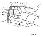
- eine teilweise freigeschnittene, perspektivische Darstellung ei- nes Fondbereichs eines Kraftfahrzeugs mit Blick auf die Innen- seite der hinteren, rechten Tür;
- Fig. 2:
- die hintere, rechte Tür gemäß
Fig. 1 mit einem erfindungsge- mäßen Seitenfensterrollo gemäß einem ersten Ausführungsbei- spiel in einer teilweise freigeschnittenen Darstellung; - Fig. 3a:
- eine Führungsnut für eine erfindungsgemäße Blockiereinrich- tung mit einem Rastelement in einer ersten Funktionsstellung;
- Fig. 3b:
- die Führungsnut gemäß
Fig. 3a mit dem Rastelement in einer zweiten Funktionsstellung; - Fig. 4:
- die hintere, rechte Tür gemäß
Fig. 1 mit einem erfindungsge- mäßen Beschattungsrollo gemäß einem zweiten Ausführungs- beispiel in einer teilweise freigeschnittenen Darstellung; - Fig. 5:
- ein Seitenfensterrollo mit einer Blockiereinrichtung gemäß ei- nem dritten Ausführungsbeispiel der Erfindung;
- Fig. 6:
- einen ersten Betriebszustand bei einer Betätigung der Blockier- einrichtung gemäß
Fig. 5 ; - Fig. 7:
- einen zweiten Betriebszustand bei einer Betätigung der Blo- ckiereinrichtung gemäß
Fig. 5 ; - Fig. 8:
- eine Blockiereinrichtung gemäß einem vierten Ausführungsbei- spiel der Erfindung während des Ausfahrens eines Rollos;
- Fig. 9:
- die Blockiereinrichtung gemäß
Fig. 8 bei Erreichen eines Schaltpunktes; - Fig. 10:
- die Blockiereinrichtung gemäß
Fig. 8 in einem verrasteten Zu- stand; - Fig. 11:
- die Blockiereinrichtung gemäß
Fig. 8 beim Lösen der Verras- tung und - Fig. 12:
- die Blockiereinrichtung gemäß
Fig. 8 beim Einfahren der Rollo- bahn.
- Fig. 1:
- a partially cutaway, perspective view of a rear area of a motor vehicle with a view of the inside of the rear right door;
- Fig. 2:
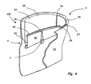
- the rear right door according to
Fig. 1 with a side window roller blind according to the invention according to a first embodiment in a partially cut-away view; - Fig. 3a:
- a guide groove for a blocking device according to the invention with a latching element in a first functional position;
- 3b:
- the guide groove according
Fig. 3a with the locking element in a second functional position; - 4:
- the rear right door according to
Fig. 1 with a shade according to the invention according to a second embodiment in a partially cut-away representation; - Fig. 5:
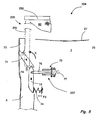
- a side window roller blind with a blocking device according to a third embodiment of the invention;
- Fig. 6:
- a first operating state upon actuation of the blocking device according to
Fig. 5 ; - Fig. 7:
- a second operating state upon actuation of the blocking device according to
Fig. 5 ; - Fig. 8:
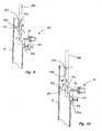
- a blocking device according to a fourth embodiment of the invention during the extension of a roller blind;
- Fig. 9:
- the blocking device according to
Fig. 8 upon reaching a switching point; - Fig. 10:
- the blocking device according to
Fig. 8 in a latched condition; - Fig. 11:
- the blocking device according to
Fig. 8 when loosening the catch and - Fig. 12:
- the blocking device according to
Fig. 8 when retracting the roller coaster.
Die in
Die Seitentür 2 weist eine Fensteröffnung 23 auf, welche in einen ersten Abschnitt 24 und einen zweiten Abschnitt 25 durch einen Steg 26 unterteilt ist. Der zweite Abschnitt 25 ist dabei als Öffnung für ein sogenanntes Dreiecksfenster gestaltet, so dass die Fensteröffnung 23 im Wesentlichen trapezförmig ist. Die Fensteröffnung 23 weist einen unteren Rand 27 und einen oberen Rand 28 auf, wobei der obere Rand 28 üblicherweise nicht parallel zu dem unteren Rand 27 verläuft, sondern gekrümmt verlaufen kann. In die Fensteröffnung 23 ist ein nicht dargestelltes, zweiteiliges Seitenfenster einsetzbar. Das Seitenfenster ist üblicherweise zumindest in dem ersten Abschnitt 24 verschieblich.The
Die Fensteröffnung 23 ist weiter durch ein erfindungsgemäßes Beschattungsrollo verdunkelbar, welches in dem Ausführungsbeispiel als Seitenfensterrollo 4 mit einer Rollobahn 40 gestaltet ist. In anderen Ausführungsformen dient ein erfindungsgemäßes Beschattungsrollo einer Abdeckung der Heckscheibenöffnung 13. Zum Abwickeln der Rollobahn 40 von einer in
Das Auszugprofil 50 ist mit der Stange 51 zum Verschieben des Auszugprofils 50 und somit zum Abwickeln der Rollobahn 40 von der Wickelwelle 43 wirkverbunden. Die Stange 51 ist zumindest teilweise in einem Hohlrohr 52 versenkbar. Die Stange 51 und/oder das Hohlrohr 52 benötigt/benötigen einigen geringen Bauraum an der Seitentür 2 und kann/können so einfach in diese integriert werden. Beim Versenken der Stange 51 wird eine Feder, beispielsweise eine Schraubendruckfeder 6 zusammengedrückt. Die Schraubendruckfeder 6 wirkt dabei als mechanisches Antriebsmittel, wobei ein Abwickeln der Rollobahn 40 aufgrund der Federkraft der Schraubendruckfeder 6 erfolgen kann und/oder dadurch unterstützt wird. In anderen Ausgestaltungen wird das Auszugprofil in einer oder zwei seitlichen Führungsschiene(n) geführt, wobei in der Führungsschiene ein Feder zum Abwickeln der Rollobahn vorgesehen sein kann. Zum Aufwickeln der Rollobahn 40 auf die Wickelwelle 43 ist vorzugsweise eine nicht dargestellte Rückstellfeder vorgesehen. Um die Rollobahn 40 in einer bestimmten Position zu halten, ist erfindungsgemäß eine Blockiereinrichtung 7 vorgesehen. Die erfindungsgemäße Blockiereinrichtung 7 umfasst eine push-push-Verriegelung, so dass die Stange 51 und/oder das Auszugprofil 50 wenigstens in einer Verstauposition der Rollobahn 40 arretierbar ist/sind, wobei die Arretierung durch ein Drücken und/oder Bewegen entgegen der Abwickelrichtung lösbar ist. In der dargestellten Ausführungsform wirkt die Blockiereinrichtung 7 mit der Stange 51 zusammen. Zu diesem Zweck umfasst in dem dargestellten Ausführungsbeispiel die Blockiereinrichtung 7 ein in
Die dargestellte Blockiereinrichtung 207 umfasst weiter einen Antrieb 75 mit einem Kolben 76, durch welchen das Schaltelement 72 betätigbar ist. Der Antrieb 75 ist beispielsweise mit einem Stellmotor gestaltet, so dass eine Betätigung durch einen Fahrer fernbedient möglich ist. Alternativ und/oder zusätzlich kann ein Stellknopf 77 vorgesehen sein, durch welchen das Schaltelement 72 betätigbar ist.The illustrated
In einer weiteren Ausgestaltung sperrt die Blockiereinrichtung 207 ein Abwickeln der Rollobahn 40.In a further embodiment, the
Durch einen Antrieb 75, beispielsweise einen Stellmotor und/oder einen Elektro-Magneten, ist ein fernbedientes Lösen und/oder Arretieren der Blockiervorrichtung 207 möglich. Zum Lösen und/oder Arretieren ist jeweils nur ein geringer Stellweg notwendig und/oder eine geringe Kraft aufzubringen. Je nach Gestaltung des Antriebsmittels für die Rollobahn 40 erfolgt nach dem Lösen der Blockiervorrichtung 207 ein automatisches Abwickeln, beispielsweise aufgrund einer Kraft einer Federspeicheranordnung, oder ein automatisches Aufwickeln, beispielsweise aufgrund einer Kraft einer Rückholfeder des Beschattungsrollos.By a
Die Blockiereinrichtung 307 umfasst einen verschwenkbaren Schaltkopf 171, welcher verschwenkbar an der Stange 251 des Seitenfensterrollos 204 gemäß
In der in
Wie in
Wie in
Dieser Verriegel- und Entriegelmechanismus gemäß den
In einer weiteren Ausgestaltung kann eine Blockiereinrichtung gemäß den
Claims (12)
- Roller shade for a motor vehicle window having a flexible planar structure (40) that can be wound onto and unwound from a winding shaft (43) and that can be moved with the aid of at least one linear guide means (5, 105, 205) from a stowed position into an at least partially unwound protection position, and having at least one releasable locking device (7, 207, 307) by which the linear guide means (5, 105, 205) can be locked in at least one position, characterized in that the locking device (7, 207, 307) comprises a push-push lock.
- Roller shade according to Claim 1, characterized in that the linear guide means (5, 105, 205) can be locked in the stowed position, where the locking device (7) can be released by applying a force to the linear guide means and/or by moving the linear guide means against an unwinding direction (A).
- Roller shade according to Claim 2, characterized in that a mechanical drive means (6) effective in the unwinding direction (A) is provided, by which the flexible planar structure (40) can be unwound from the winding shaft (43) after a release of the locking device (7).
- Roller shade according to Claim 3, characterized in that the mechanical drive means (6) is designed as a spring-loaded arrangement.
- Roller shade according to one of Claims 1 to 4, characterized in that the locking device (7) comprises at least one engaging element (70) interacting with the linear guide means (5, 105, 205) to achieve locking.
- Roller shade according to Claim 5, characterized in that the linear guide means (5, 105, 205) comprises a guide groove (54) inside which the engaging element (70) is guided, the guide groove (54) having at least one engagement position (57).
- Roller shade according to Claim 6, characterized in that the guide groove (54) has at least in some sections the form of a cardioid.
- Roller shade according to one of Claims 1 to 7, characterized in that an actuation direction of the push-push lock runs transversely to the unwinding direction (A), in particular at an angle of about 90°.
- Roller shade according to Claim 8, characterized in that the linear guide means (5, 105, 205) has a pivotable switch (71, 171) and the locking device (207, 307) has at least one movable switching element (72, 172) for actuating the switch, where the switch (71, 171) and the switching element (72, 172) interact to lock the linear guide means (5, 105, 205).
- Roller shade according to one of Claims 1 to 8, characterized in that the locking device (7, 207, 307) comprises a drive, in particular a servomotor and/or a magnet.
- Roller shade according to one of Claims 1 to 10, characterized in that the linear guide means (5, 105, 205) comprises at least one rod (51, 251) which is operatively connected to a pull-out strip (50, 250) attached to the flexible planar structure (40) for transmission of the movement.
- Roller shade according to Claim 11, characterized in that the linear guide means (5, 105, 205) comprises at least one telescopic rod (151) which is operatively connected to the pull-out section (50, 250) attached to the flexible planar structure (40) for transmission of the movement.
Applications Claiming Priority (1)
| Application Number | Priority Date | Filing Date | Title |
|---|---|---|---|
| DE102007035043A DE102007035043A1 (en) | 2007-07-20 | 2007-07-20 | Shading blind with blind lock |
Publications (2)
| Publication Number | Publication Date |
|---|---|
| EP2017107A1 EP2017107A1 (en) | 2009-01-21 |
| EP2017107B1 true EP2017107B1 (en) | 2011-03-02 |
Family
ID=39047418
Family Applications (1)
| Application Number | Title | Priority Date | Filing Date |
|---|---|---|---|
| EP08011898A Expired - Fee Related EP2017107B1 (en) | 2007-07-20 | 2008-07-02 | Shade roller with roller lock |
Country Status (6)
| Country | Link |
|---|---|
| US (1) | US20090020236A1 (en) |
| EP (1) | EP2017107B1 (en) |
| JP (1) | JP2009023648A (en) |
| KR (1) | KR101605841B1 (en) |
| CN (1) | CN101349141B (en) |
| DE (3) | DE102007035043A1 (en) |
Cited By (1)
| Publication number | Priority date | Publication date | Assignee | Title |
|---|---|---|---|---|
| DE102014211619A1 (en) | 2013-06-28 | 2014-12-31 | Bos Gmbh & Co. Kg | Shading device for a glass surface area of a motor vehicle |
Families Citing this family (18)
| Publication number | Priority date | Publication date | Assignee | Title |
|---|---|---|---|---|
| DE102008020541A1 (en) * | 2008-04-24 | 2009-10-29 | GM Global Technology Operations, Inc., Detroit | Sun visor device for the window pane of a motor vehicle and motor vehicle with such a sun visor device |
| DE102008063775A1 (en) * | 2008-12-18 | 2010-07-01 | Audi Ag | Vehicle window roller blind comprises roller blind web for shading vehicle window with window frame, and winding unit for winding and unwinding roller blind web |
| DE102009038185A1 (en) * | 2009-08-20 | 2011-02-24 | GM Global Technology Operations, Inc., Detroit | Motor vehicle with windshield, separate roof window and retractable roller blind |
| KR101106937B1 (en) * | 2010-01-13 | 2012-01-19 | (주)수퍼플랫 | Lighting apparatus for installing street light |
| TW201139173A (en) * | 2010-05-06 | 2011-11-16 | Macauto Ind Co Ltd | Semi-automatic type sunshade curtain device |
| CN102606056A (en) * | 2011-01-19 | 2012-07-25 | 皇田工业股份有限公司 | Semi-automatic sun-shading curtain device |
| US20130020040A1 (en) * | 2011-07-20 | 2013-01-24 | Paul Lin | Sunshade Assembly Having a Locking Mechanism |
| DE102012204592A1 (en) * | 2012-03-22 | 2013-09-26 | Schaeffler Technologies AG & Co. KG | Rotatable connector for patient bed i.e. rotatable patient bed, has locking unit whose parts are respectively connected with bearing rings in engagement with each other with predetermined relative positions of bearing rings |
| JP5985239B2 (en) * | 2012-04-26 | 2016-09-06 | 芦森工業株式会社 | Shade device |
| DE102014004247B4 (en) | 2014-03-25 | 2017-08-17 | Lisa Dräxlmaier GmbH | Locking device with a plurality of Haltepositonen |
| KR101601497B1 (en) | 2014-10-02 | 2016-03-08 | 현대자동차주식회사 | Roller blinds for car a curtain device |
| US10336165B2 (en) | 2015-05-01 | 2019-07-02 | Ford Global Technologies, Llc | Spring-activated extendable sun visor blade |
| JP6629049B2 (en) * | 2015-11-18 | 2020-01-15 | 芦森工業株式会社 | Shade device for vehicle |
| DE102016111658B4 (en) * | 2016-06-24 | 2022-07-21 | Macauto Industrial Co., Ltd. | Shading device for a vehicle |
| CN105952363B (en) * | 2016-06-24 | 2018-11-23 | 深圳品彦室内设计有限公司 | A kind of roller shutter is from open system |
| US10661638B2 (en) * | 2016-06-24 | 2020-05-26 | Macauto Industrial Co., Ltd | Shade arrangement for vehicle |
| WO2020252253A1 (en) | 2019-06-12 | 2020-12-17 | Shanghai Yanfeng Jinqiao Automotive Trim Systems Co. Ltd. | Vehicle component |
| DE102019004378A1 (en) | 2019-06-19 | 2019-12-19 | Daimler Ag | Roller blind for a motor vehicle |
Family Cites Families (14)
| Publication number | Priority date | Publication date | Assignee | Title |
|---|---|---|---|---|
| DE3737707A1 (en) * | 1987-11-06 | 1989-05-24 | Clauss Markisen | LOCKABLE UPPER AWNING |
| DE4241138C2 (en) * | 1992-12-07 | 1995-07-20 | Baumeister & Ostler Gmbh Co | Sun protection roller blind for motor vehicles |
| DE19806736C2 (en) * | 1998-02-18 | 2003-06-05 | Bos Gmbh | Protective device for a window of a motor vehicle |
| CN2338200Y (en) * | 1998-06-29 | 1999-09-15 | 郑博文 | Electric sun visor for automobiles back windows |
| US6056333A (en) * | 1998-09-08 | 2000-05-02 | Illinois Tool Works Inc. | Floating latch mechanism |
| CN2452784Y (en) * | 2000-11-20 | 2001-10-10 | 吴伟良 | Automobile sun-shade curtain |
| ITTV20010035A1 (en) * | 2001-03-30 | 2002-09-30 | Bettio Group Srl | MOSQUITO NET WITH HOOKING DEVICE AND QUICK RELEASE OF THE HANDLE BAR |
| DE20112948U1 (en) | 2001-07-27 | 2001-10-25 | Bos Gmbh | Privacy protection device for a motor vehicle window |
| DE10237231B3 (en) * | 2002-08-14 | 2004-02-19 | Bos Gmbh & Co. Kg | Window roller blind with bidirectional operating elements |
| CN2579709Y (en) * | 2002-10-16 | 2003-10-15 | 陈英文 | Automatic sunshade curtain device of automobile rear window |
| DE202004014652U1 (en) * | 2004-09-14 | 2006-03-02 | Brose Fahrzeugteile Gmbh & Co. Kommanditgesellschaft, Coburg | Door for a vehicle comprises a window blind with a blind path which moves parallel to the window pane using a mechanism a part of which is guided on the window lifter guide rail |
| DE102005029560A1 (en) * | 2005-04-21 | 2006-11-02 | Bos Gmbh & Co. Kg | Roller blind with anti-trap protection |
| DE202005020611U1 (en) * | 2005-04-21 | 2006-04-27 | Bos Gmbh & Co. Kg | Roller blind for motor vehicle with clamping protection has brake that introduces at least part of thrust into guide rail when deceleration force greater than certain value is applied to bar attached to end of blind |
| DE202007016325U1 (en) * | 2007-09-18 | 2008-02-07 | Bos Gmbh & Co. Kg | Covering device for a displaceably mounted vehicle window |
-
2007
- 2007-07-20 DE DE102007035043A patent/DE102007035043A1/en not_active Ceased
- 2007-07-20 DE DE202007016327U patent/DE202007016327U1/en not_active Expired - Lifetime
-
2008
- 2008-07-02 DE DE502008002710T patent/DE502008002710D1/en active Active
- 2008-07-02 EP EP08011898A patent/EP2017107B1/en not_active Expired - Fee Related
- 2008-07-16 JP JP2008185092A patent/JP2009023648A/en active Pending
- 2008-07-18 KR KR1020080070106A patent/KR101605841B1/en not_active IP Right Cessation
- 2008-07-18 US US12/218,847 patent/US20090020236A1/en not_active Abandoned
- 2008-07-21 CN CN200810131667XA patent/CN101349141B/en not_active Expired - Fee Related
Cited By (3)
| Publication number | Priority date | Publication date | Assignee | Title |
|---|---|---|---|---|
| DE102014211619A1 (en) | 2013-06-28 | 2014-12-31 | Bos Gmbh & Co. Kg | Shading device for a glass surface area of a motor vehicle |
| DE102014211617A1 (en) | 2013-06-28 | 2014-12-31 | Bos Gmbh & Co. Kg | Shading device for a glass surface area of a motor vehicle |
| US9132718B2 (en) | 2013-06-28 | 2015-09-15 | Bos Gmbh & Co. Kg | Shading device for a glass surface region of a motor vehicle |
Also Published As
| Publication number | Publication date |
|---|---|
| CN101349141B (en) | 2013-07-31 |
| JP2009023648A (en) | 2009-02-05 |
| KR20090009749A (en) | 2009-01-23 |
| US20090020236A1 (en) | 2009-01-22 |
| EP2017107A1 (en) | 2009-01-21 |
| KR101605841B1 (en) | 2016-03-23 |
| DE202007016327U1 (en) | 2008-02-07 |
| DE502008002710D1 (en) | 2011-04-14 |
| CN101349141A (en) | 2009-01-21 |
| DE102007035043A1 (en) | 2009-01-22 |
Similar Documents
| Publication | Publication Date | Title |
|---|---|---|
| EP2017107B1 (en) | Shade roller with roller lock | |
| EP1736335B1 (en) | Roller blind for rear window with complete slot cover by the pull-out element | |
| DE10228028B3 (en) | Rear window roller blind with lift cassette | |
| DE102006058598B4 (en) | Triangular window blind for motor vehicles | |
| EP1533158B1 (en) | Side window roller blind system comprising a window contour part | |
| DE10014760B4 (en) | Rear window roller blind with sprung wheels | |
| EP1905625A1 (en) | Roller blind with undercut-free guide rail | |
| DE202006011452U1 (en) | Roller blind in particular for rear window of vehicle, comprises telescopic transversally positioned pulling bar | |
| DE10064513A1 (en) | Roller blind or covering is for winding and unwinding sheet, foil or netting arranged at window or boot of road vehicle, sheet at one end being fixed to winding shaft and with second end to draw-out rod | |
| EP1666290B1 (en) | Roller blind arrangement with hidden latching system | |
| EP0601454A1 (en) | Roller blind for motor vehicle | |
| EP1848604B1 (en) | Shading device comprising a roller blind that can be manually actuated and assume several positions | |
| DE3523391A1 (en) | Edge guard for a motor-vehicle door | |
| DE10248958A1 (en) | Sub-assembly has braking element for slide to engage in corresponding braking slot in guide rail for locking purposes, whereby slide has spring loaded support element to assist engagement of braking element in slot | |
| DE19952125C1 (en) | Vehicle roll bar structure has a cassette with a double stroke action to push out a center section and extend the upper roll bar section in virtually simultaneous movements on rolling over | |
| EP1223299B1 (en) | Roller blind, in particular insect screen | |
| EP2014493B1 (en) | Lateral guide for a roller blind and roller blind for motor vehicles | |
| EP1186482B1 (en) | Cartridge for a rollover protection system guiding an expandable and retractable rollbar | |
| DE10144523A1 (en) | Roll-up covering for vehicle window has winder-shaft and pull-out bar, plastic web-holder, stop-piece, handle and piping in hollow profile | |
| DE202007004175U1 (en) | vehicle blind | |
| DE102015200050A1 (en) | Sunblind | |
| WO2011086084A1 (en) | Roller blind device | |
| DE10200113B4 (en) | Locks | |
| DE202007015435U1 (en) | Roof window roller blind with preloaded glides | |
| DE102016209004A1 (en) | Side window shading device for a motor vehicle |
Legal Events
| Date | Code | Title | Description |
|---|---|---|---|
| PUAI | Public reference made under article 153(3) epc to a published international application that has entered the european phase |
Free format text: ORIGINAL CODE: 0009012 |
|
| AK | Designated contracting states |
Kind code of ref document: A1 Designated state(s): AT BE BG CH CY CZ DE DK EE ES FI FR GB GR HR HU IE IS IT LI LT LU LV MC MT NL NO PL PT RO SE SI SK TR |
|
| AX | Request for extension of the european patent |
Extension state: AL BA MK RS |
|
| AKX | Designation fees paid | ||
| 17P | Request for examination filed |
Effective date: 20091014 |
|
| RBV | Designated contracting states (corrected) |
Designated state(s): DE FR SE |
|
| RBV | Designated contracting states (corrected) |
Designated state(s): DE FR SE |
|
| RBV | Designated contracting states (corrected) |
Designated state(s): DE FR SE |
|
| GRAP | Despatch of communication of intention to grant a patent |
Free format text: ORIGINAL CODE: EPIDOSNIGR1 |
|
| GRAS | Grant fee paid |
Free format text: ORIGINAL CODE: EPIDOSNIGR3 |
|
| GRAA | (expected) grant |
Free format text: ORIGINAL CODE: 0009210 |
|
| AK | Designated contracting states |
Kind code of ref document: B1 Designated state(s): DE FR SE |
|
| REF | Corresponds to: |
Ref document number: 502008002710 Country of ref document: DE Date of ref document: 20110414 Kind code of ref document: P |
|
| REG | Reference to a national code |
Ref country code: DE Ref legal event code: R096 Ref document number: 502008002710 Country of ref document: DE Effective date: 20110414 |
|
| PG25 | Lapsed in a contracting state [announced via postgrant information from national office to epo] |
Ref country code: SE Free format text: LAPSE BECAUSE OF FAILURE TO SUBMIT A TRANSLATION OF THE DESCRIPTION OR TO PAY THE FEE WITHIN THE PRESCRIBED TIME-LIMIT Effective date: 20110302 |
|
| PLBE | No opposition filed within time limit |
Free format text: ORIGINAL CODE: 0009261 |
|
| STAA | Information on the status of an ep patent application or granted ep patent |
Free format text: STATUS: NO OPPOSITION FILED WITHIN TIME LIMIT |
|
| 26N | No opposition filed |
Effective date: 20111205 |
|
| REG | Reference to a national code |
Ref country code: DE Ref legal event code: R097 Ref document number: 502008002710 Country of ref document: DE Effective date: 20111205 |
|
| PGFP | Annual fee paid to national office [announced via postgrant information from national office to epo] |
Ref country code: FR Payment date: 20130719 Year of fee payment: 6 |
|
| REG | Reference to a national code |
Ref country code: FR Ref legal event code: ST Effective date: 20150331 |
|
| PG25 | Lapsed in a contracting state [announced via postgrant information from national office to epo] |
Ref country code: FR Free format text: LAPSE BECAUSE OF NON-PAYMENT OF DUE FEES Effective date: 20140731 |
|
| PGFP | Annual fee paid to national office [announced via postgrant information from national office to epo] |
Ref country code: DE Payment date: 20170726 Year of fee payment: 10 |
|
| REG | Reference to a national code |
Ref country code: DE Ref legal event code: R119 Ref document number: 502008002710 Country of ref document: DE |
|
| PG25 | Lapsed in a contracting state [announced via postgrant information from national office to epo] |
Ref country code: DE Free format text: LAPSE BECAUSE OF NON-PAYMENT OF DUE FEES Effective date: 20190201 |