EP2017097A1 - Attelage pour véhicules automobiles - Google Patents
Attelage pour véhicules automobiles Download PDFInfo
- Publication number
- EP2017097A1 EP2017097A1 EP08011159A EP08011159A EP2017097A1 EP 2017097 A1 EP2017097 A1 EP 2017097A1 EP 08011159 A EP08011159 A EP 08011159A EP 08011159 A EP08011159 A EP 08011159A EP 2017097 A1 EP2017097 A1 EP 2017097A1
- Authority
- EP
- European Patent Office
- Prior art keywords
- ball
- joint
- condyle
- trailer coupling
- socket
- Prior art date
- Legal status (The legal status is an assumption and is not a legal conclusion. Google has not performed a legal analysis and makes no representation as to the accuracy of the status listed.)
- Granted
Links
Images

Classifications
-
- B—PERFORMING OPERATIONS; TRANSPORTING
- B60—VEHICLES IN GENERAL
- B60D—VEHICLE CONNECTIONS
- B60D1/00—Traction couplings; Hitches; Draw-gear; Towing devices
- B60D1/48—Traction couplings; Hitches; Draw-gear; Towing devices characterised by the mounting
- B60D1/54—Traction couplings; Hitches; Draw-gear; Towing devices characterised by the mounting collapsible or retractable when not in use, e.g. hide-away hitches
-
- B—PERFORMING OPERATIONS; TRANSPORTING
- B60—VEHICLES IN GENERAL
- B60D—VEHICLE CONNECTIONS
- B60D1/00—Traction couplings; Hitches; Draw-gear; Towing devices
- B60D1/01—Traction couplings or hitches characterised by their type
- B60D1/06—Ball-and-socket hitches, e.g. constructional details, auxiliary devices, their arrangement on the vehicle
Definitions
- the invention relates to a towing hitch for motor vehicles comprising a vehicle-mounted pivotally mounted ball rod, which at its free. End bears a coupling ball and at least in their operating position, but preferably both in their operating position and its rest position, rotatably secured via engageable form-fitting contours of a ball rod bearing head and on the other hand, a component opposite thereto, wherein the ball rod bearing head and this opposite component the joint head and the Form joint socket of a ball joint and between the joint head and the joint socket a path control of the ball rod bearing head is arranged, which causes a change in the position of the pivot axis during pivoting of the ball rod from the operating position to the rest position.
- the positive connection consists in particular of balls and these oppositely associated calottes.
- the ball rod bearing head is formed in its release position as a three-axis pivotable joint with a path control of the ball rod bearing head to adjust the pivotal movement of the trailer coupling in a simple manner to the different space conditions in different vehicles. This adjustment is not possible with conventional, pivotable to a single axis towbars on every vehicle.
- the three-axis joint is designed as a ball head, which forms a ball joint with a half-shell-like, surrounding the ball head housing of the ball bearing head.
- the ball head itself is arranged on a hollow shaft, in which the lock is integrated for engaging the balls in the calotte both in the working position and in the rest position.
- Lock When Lock is used guided in the hollow shaft, externally operable locking pin and cooperating with this in radial bores locking means.
- the locking means are out of the locking pin in the radial bores outwardly depressible balls which engage in a circumferential groove in the ball rod bearing head and thereby cause the rotationally fixed fixing of the ball rod bearing head by means of positive locking contours.
- the tumbling motion causing path control is in the form of a backdrop. In this scenery pins engage, which are arranged in a connected to the ball rod bearing head retaining ring.
- a disadvantage of the hitch after the EP 1 533 149 A1 is that in addition to the form-fitting contours additionally engageable and disengageable locking means are provided to bring the positive locking contours in the rotary end positions in engagement.
- the present invention seeks to constructively simplify a generic trailer coupling for motor vehicles and to improve the handling of the trailer coupling.
- the joint is designed as a ball joint, in which a joint head has a spherical shape, which surrounds the socket preferably captive.
- the torsion-proof fixing of the ball-rod bearing head in the operating position or both in the rest position and in the operating position takes place exclusively via the engagement of the positive-locking contours.
- only a path control between the condyle and socket is provided, which causes a change in the position of the pivot axis when pivoting the ball rod from one to the other end position and thus leads to the advantageous tumbling, space and space-saving pivoting the ball rod in their respective Drehendlagen ,
- the path control can be during pivoting, be it by hand or motor, realize variable pivoting movements of the ball bar, in particular to pivot the ball bar with the least possible movement space in an invisible rest position.
- the pivoting kinematics determined by the path control system makes it possible within wide limits to adapt to the different positions and geometries of the rest position spaces of different motor vehicles, to which a trailer coupling according to the invention is attached.
- a first embodiment of the invention for assembly purposes preferably multi-part ball rod bearing head engages around this opposite, vehicle-mounted as a joint socket Component that forms the condyle of the ball joint.
- This embodiment of the articulated connection has the advantage that the lock can be particularly easy to integrate into engaging the form-fitting contours in which attaches to the condyle of the ball joint a preferably integrally formed with the condyle hollow shaft whose cavity extends into the condyle of the ball joint , wherein in the cavity, the axially acting locking is arranged for engaging the form-fitting contours in the operating position, but preferably in the two Drehendlagen.
- the ball rod In the rest position, the ball rod can alternatively be determined by means of a clamping or locking mechanism.
- the axially acting latch for releasing the positive locking contours is arranged in the vehicle-mounted component, so that the actuating means for locking are not located on a movably mounted Tei.
- the ball rod bearing head the spherical joint head and this opposite, mounted on the vehicle component form the socket of the ball joint.
- the joint pan forming member is preferably formed in several parts, to assemble the ball rod bearing head unproblematic.
- the axially acting locking device preferably comprises a locking pin guided in the cavity and balls which can be inserted and disengaged into calottes.
- Each calotte is located in the socket.
- each rotary end position preferably has a plurality of calottes and associated balls guided in radial passages.
- the balls are located in preferably radially extending passageways of the condyle which extend between the cavity and the outer surface of the condyle. Due to the shape of the locking pin, the balls in each passage can be moved back and forth by axial displacement of the locking pin in the passage and thereby engage or disengage into the calottes of the socket.
- the locking pin may, for example, in cross-section circular cylindrical or slightly conical, but self-locking portions of different diameters having a conically formed transition between the sections to move the balls in the passages.
- means for disengaging the form-fitting contours are arranged in the joint socket.
- the means for disengaging the form-fitting contours preferably comprise a spring-loaded pin which emerges in the calotte surface and acts on the ball in the direction of the longitudinal axis of the radial passage in the joint head.
- all form-fitting contours are preferably equipped with such spring-loaded pins.
- the path control is designed as a backdrop with at least one engaging in the backdrop sequential means.
- the scenery is designed in particular as a radial groove in the condyle with on the one condyle half opposite to the other condyle half directed course.
- a follower for example, pins, or bolts into consideration.
- the pivoting resistance of each sequential means is preferably arranged in a blind hole of the socket ball, which is spring-loaded in the direction of the circular section in cross-section radial groove.
- the two front ends of the groove can serve as stops for the following means, for example.
- the groove track is formed circumferentially and the pivotal movement in the Drehendlagen the trailer coupling of the ball rod is limited by vehicle-fixed stops.
- the balls of the form-fitting contours are eccentrically engageable in the calotte.
- results in the end positions of the ball rod a tension between the condyle and socket, the relative movements in the joint and thus wear counteracts between ball bearing head and the opposite component.
- the hitch (1) comprises a pivotally mounted ball bar (2) which carries at its free end a coupling ball (3) and both in their in FIG. 1 shown in phantom position as well as in the operating position shown in solid lines on and disengageable positive locking contours of a ball rod bearing head (4) and on the other hand, a component opposite this (5) rotatably fixed.
- the ball rod bearing head (4) holding the ball rod (2) forms the joint socket of a ball joint, which engages around the opposite, spherical ball joint forming component (5) in a form-fitting and captive manner.
- the condyle forming member (5) is on the vehicle, for example one for attaching the hitch to the vehicle attached cross member attached, the sake of clarity in FIG. 1 not shown.
- Integrally formed on the component (5) is a hollow shaft (6) whose cavity (7) extends into the joint head, the diameter of the cavity expanding in three cylindrical or slightly conical sections (8, 9, 10) and the transitions between the sections (8, 9, 10) are conical.
- an axially acting locking in the form of a locking bolt (16) is reciprocally guided, wherein the locking pin (16) with the cavity corresponding cylindrical or slightly conical sections (11, 12, 13) with different diameters has, which are connected via conical sections (14, 15) as transitions with each other.
- the length of the sections of the stepped executed locking bolt (16) and the stepped formed cavity (7) and the inclination angle of the arranged between the sections conical transitions are coordinated, so that the path of movement of the locking pin by the reaching surfaces of the conical, the transitions forming sections of locking pin (16) and cavity (7) on the one hand and the front end (18) of the cavity (7) on the other hand is limited.
- the in the cavity (7) guided locking pin (16) is against the force of a compression spring (19) by means of a total of (33) designated actuating member of the in FIG. 1 shown in solid lines locking position (20) for the positive locking contours in a release position shown in dashed lines (21) movable.
- the compression spring (19) is supported on the one hand on the outwardly facing end side of the hollow shaft (6) and on the other hand on a support disc (34) which projects beyond the hollow shaft (6) part of the cylindrical portion (11) of the locking pin (16 ) with a in a circumferential groove guided circlip (35) is fixed in the locking pin.
- the spring (19) could also bear against the front side of the section (13) of the locking bolt.
- a conical compression spring is used, in which the spiral windings compress under pressure into each other and reduces the axial block length. As a result, a short overall length for the frontal space for receiving the compression spring is made possible.
- the actuator (33) is formed in the illustrated embodiment by a on the locking pin (16) adjoining rack drive whose rack (36) with the locking pin (16) and can be made in one piece with this.
- the gear (37) engaging in the toothed rack (36) may, for example, be connected to a handle, a lever or a motor drive.
- the locking position (20) presses the largest diameter having at least partially slightly conical portion (13) of the locking pin (16) arranged in six radial passages (22) balls (23) in calotte (24), whereby the ball rod bearing head (4) is fixed against rotation relative to the component (5).
- the slightly conical design of the portion (13) compensates for a particular wear-related game in the form-fitting contours (23,24).
- the conicity of the portion (13) is determined so that a self-locking of the locking pin (16) even with large static and dynamic forces, which are transmitted from the balls (23) on the portion (13) guaranteed.
- This self-locking is ensured at angles of up to 3 ° relative to the longitudinal axis (17) even with dynamic loads.
- the angle can be up to 9 °.
- the portion of the portion (13) immediately adjacent to the transition forming portion (15) should be cylindrical to ensure self-locking under dynamic load peaks.
- spring-loaded pins (25) are arranged in the ball-rod bearing head (4). which emerge in the center of the spherical surface and act in the direction of the radial passages (22) on the balls (23).
- These spring-loaded pins (25) are compulsory to arrange at the radial passages (22), in which the balls (23) fall into the calottes (24) as a result of gravity. If, however, only radial passages are arranged in the hemisphere of the component (5) pointing upwards in the installed position, can basically be dispensed with the spring-loaded pins.
- a web control (26) which controls the rotational movement of the ball rod bearing head (4) about the opposite component (5) of the ball joint.
- the web control (26) is formed as a circumferential radial groove (27) in the component (5), in which a follower means in the form of a spring-loaded ball (28) engages.
- the spring-loaded ball (28) is guided in a blind hole of the ball socket bearing head (4) forming the socket and protrudes approximately halfway beyond the surface of the socket and with this part into the radial groove (27).
- the pivoting movement between the working and rest position of the ball rod (2) is limited in the present embodiment, characterized in that on the vehicle-fixed component (5) stops are provided, where the ball rod bearing head comes into abutment in its end positions.
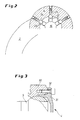
- FIG. 3 For mounting of the rod end encompassing ball rod bearing head (4) this is made in two parts, as shown in FIG. 3 is shown.
- the part (30) connected to the ball rod (2) is screwed to a further part (31) which completes the joint socket.
- Each of the two parts forming the socket (30, 31) extends over a partial surface of the spherical joint head, which in each case is inadequate for captively grasping the joint head with one of the parts (30, 31) alone. Only the two by means of the screw (32) connected parts (30, 31) together form the joint head encompassing the socket.
Landscapes
- Engineering & Computer Science (AREA)
- Transportation (AREA)
- Mechanical Engineering (AREA)
- Pivots And Pivotal Connections (AREA)
Applications Claiming Priority (1)
| Application Number | Priority Date | Filing Date | Title |
|---|---|---|---|
| DE102007029051A DE102007029051A1 (de) | 2007-06-21 | 2007-06-21 | Anhängekupplung für Kraftfahrzeuge |
Publications (2)
| Publication Number | Publication Date |
|---|---|
| EP2017097A1 true EP2017097A1 (fr) | 2009-01-21 |
| EP2017097B1 EP2017097B1 (fr) | 2012-07-25 |
Family
ID=38353376
Family Applications (1)
| Application Number | Title | Priority Date | Filing Date |
|---|---|---|---|
| EP20080011159 Active EP2017097B1 (fr) | 2007-06-21 | 2008-06-19 | Attelage pour véhicules automobiles |
Country Status (2)
| Country | Link |
|---|---|
| EP (1) | EP2017097B1 (fr) |
| DE (1) | DE102007029051A1 (fr) |
Cited By (4)
| Publication number | Priority date | Publication date | Assignee | Title |
|---|---|---|---|---|
| EP2325029A1 (fr) * | 2009-11-20 | 2011-05-25 | ZF Friedrichshafen AG | Module de basculement de sphère |
| DE102012216794A1 (de) * | 2012-09-19 | 2014-03-20 | Zf Friedrichshafen Ag | Kugelschwenkmodul |
| CN110588260A (zh) * | 2019-08-27 | 2019-12-20 | 江苏大学 | 一种防松拖挂式房车的连接球头及连接系统 |
| EP4124475A1 (fr) * | 2021-07-26 | 2023-02-01 | Zhejiang Zhiyou Automotive Technology Co., Ltd. | Coupleur d'attelage de remorque |
Families Citing this family (11)
| Publication number | Priority date | Publication date | Assignee | Title |
|---|---|---|---|---|
| DE102008018739A1 (de) * | 2008-04-14 | 2009-10-15 | Trw Automotive Gmbh | Fahrzeugseitige Kupplungsbaugruppe einer Anhängerkupplung |
| DE102009045275B4 (de) * | 2009-10-02 | 2014-01-09 | Zf Friedrichshafen Ag | Schwenkmodul für eine Anhängerkupplung |
| DE102010032991A1 (de) * | 2010-07-31 | 2012-02-02 | Westfalia-Automotive Gmbh | Anhängekupplung |
| EP2412550B1 (fr) * | 2010-07-31 | 2016-02-10 | WESTFALIA - Automotive GmbH | Attelage |
| DE102011078007A1 (de) * | 2011-06-22 | 2012-12-27 | Zf Friedrichshafen Ag | Anhängevorrichtung |
| EP2650148B1 (fr) * | 2012-04-12 | 2019-03-20 | Brink Towing Systems B.V. | Partie sphérique d'un agencement de crochet de remorquage d'un véhicule |
| DE102013012303A1 (de) | 2012-08-03 | 2014-02-06 | Westfalia-Automotive Gmbh | Anhängekupplung mit einer Verriegelungseinrichtung |
| GB2505712A (en) * | 2012-09-11 | 2014-03-12 | C P Witter Ltd | Trigger assembly and detachable tow ball |
| DE102012216798A1 (de) | 2012-09-19 | 2014-03-20 | Zf Friedrichshafen Ag | Kugelschwenkmodul |
| DE102013007117A1 (de) * | 2013-04-21 | 2014-10-23 | Westfalia-Automotive Gmbh | Anhängekupplung |
| DE102020111469A1 (de) * | 2020-04-27 | 2021-10-28 | ACPS Automotive GmbH | Anhängekupplung |
Citations (4)
| Publication number | Priority date | Publication date | Assignee | Title |
|---|---|---|---|---|
| EP1504928A1 (fr) * | 2003-08-08 | 2005-02-09 | Westfalia Automotive GmbH & Co. KG | Attache remorque |
| EP1533149A1 (fr) | 2003-11-21 | 2005-05-25 | Westfalia Automotive GmbH & Co. KG | Attelage pour vehicules |
| EP1557299A1 (fr) * | 2004-01-22 | 2005-07-27 | ORIS FAHRZEUGTEILE HANS RIEHLE GmbH | Attelage de remorque |
| WO2005110781A1 (fr) * | 2004-05-14 | 2005-11-24 | Thule Towing Systems B.V. | Crochet de remorquage tournant pour vehicule |
Family Cites Families (4)
| Publication number | Priority date | Publication date | Assignee | Title |
|---|---|---|---|---|
| CH83831A (de) * | 1919-04-19 | 1920-06-01 | Werner Amrein | Vorrichtung zur winkligen Verstellung und Einstellung zweier Teile zueinander |
| DE29601156U1 (de) * | 1996-01-24 | 1996-03-28 | Westfalia Werke Knoebel | Kupplungskugelträger für Fahrzeuganhängerkupplungen |
| DE202005014499U1 (de) * | 2004-09-14 | 2005-12-22 | Mvg Metallverarbeitungsgesellschaft Mbh | Anhängekupplung |
| DE102004044912A1 (de) * | 2004-09-14 | 2006-03-30 | Mvg Metallverarbeitungsgesellschaft Mbh | Anhängekupplung mit Kugelgelenk |
-
2007
- 2007-06-21 DE DE102007029051A patent/DE102007029051A1/de not_active Withdrawn
-
2008
- 2008-06-19 EP EP20080011159 patent/EP2017097B1/fr active Active
Patent Citations (4)
| Publication number | Priority date | Publication date | Assignee | Title |
|---|---|---|---|---|
| EP1504928A1 (fr) * | 2003-08-08 | 2005-02-09 | Westfalia Automotive GmbH & Co. KG | Attache remorque |
| EP1533149A1 (fr) | 2003-11-21 | 2005-05-25 | Westfalia Automotive GmbH & Co. KG | Attelage pour vehicules |
| EP1557299A1 (fr) * | 2004-01-22 | 2005-07-27 | ORIS FAHRZEUGTEILE HANS RIEHLE GmbH | Attelage de remorque |
| WO2005110781A1 (fr) * | 2004-05-14 | 2005-11-24 | Thule Towing Systems B.V. | Crochet de remorquage tournant pour vehicule |
Cited By (6)
| Publication number | Priority date | Publication date | Assignee | Title |
|---|---|---|---|---|
| EP2325029A1 (fr) * | 2009-11-20 | 2011-05-25 | ZF Friedrichshafen AG | Module de basculement de sphère |
| DE102012216794A1 (de) * | 2012-09-19 | 2014-03-20 | Zf Friedrichshafen Ag | Kugelschwenkmodul |
| EP2711210A2 (fr) | 2012-09-19 | 2014-03-26 | ZF Friedrichshafen AG | Module de basculement de sphère |
| CN110588260A (zh) * | 2019-08-27 | 2019-12-20 | 江苏大学 | 一种防松拖挂式房车的连接球头及连接系统 |
| CN110588260B (zh) * | 2019-08-27 | 2022-11-18 | 江苏大学 | 一种防松拖挂式房车的连接球头及连接系统 |
| EP4124475A1 (fr) * | 2021-07-26 | 2023-02-01 | Zhejiang Zhiyou Automotive Technology Co., Ltd. | Coupleur d'attelage de remorque |
Also Published As
| Publication number | Publication date |
|---|---|
| DE102007029051A1 (de) | 2009-01-02 |
| EP2017097B1 (fr) | 2012-07-25 |
Similar Documents
| Publication | Publication Date | Title |
|---|---|---|
| EP2017097B1 (fr) | Attelage pour véhicules automobiles | |
| EP2163410B1 (fr) | Attelage pour véhicules automobiles | |
| DE10354753B4 (de) | Anhängekupplung für Kraftfahrzeuge | |
| EP2277724B1 (fr) | Attelage | |
| EP1799396B1 (fr) | Dispositif de remplacement pour tetes de serrage comportant plusieurs machoires de serrage | |
| DE102018206261B4 (de) | Verschiebevorrichtung | |
| DE202005002585U1 (de) | Elektromotorischer Linearantrieb | |
| EP2474430B1 (fr) | Attelage | |
| EP1484275B1 (fr) | Unité de verrouillage et d'actionnement pour un dispositif de verrouillage latéral d'une flèche | |
| DE502011004730C5 (de) | Verriegelungskopf | |
| EP1407901B2 (fr) | Attelage pour véhicules de traction | |
| DE102020101057B3 (de) | Aufbau eines Drehmomentschlüssels | |
| DE602004002378T2 (de) | Elektromechanischer linearspindelantrieb für feststellbremse | |
| WO2014005712A1 (fr) | Dispositif d'assemblage articulé | |
| EP2799261B1 (fr) | Attelage | |
| EP1419320B1 (fr) | Dispositif pour l'actionnement d'un cable | |
| DE102009045276A1 (de) | Kugelgelenk | |
| WO2014009428A1 (fr) | Dispositif pour presser une crémaillère contre un pignon | |
| DE102010043164B4 (de) | Kugelschwenkmodul für eine Anhängerkupplung | |
| EP2316673B1 (fr) | Dispositif de liaison pour un attelage ou un support de charge | |
| EP3230647B1 (fr) | Élément de logement d'un raccord à sec pour fluide et raccord à sec pour fluide équipé dudit élément | |
| EP2692554B1 (fr) | Attelage doté d'un dispositif de verrouillage | |
| DE3917828C1 (en) | Hydraulic socket spanner with revolving ring - has piston linked to piston rod connected to ratchet | |
| DE102019109398B4 (de) | Anhängerkupplung | |
| DE102006043430B4 (de) | Verriegelung für eine Anhängerkupplung |
Legal Events
| Date | Code | Title | Description |
|---|---|---|---|
| PUAI | Public reference made under article 153(3) epc to a published international application that has entered the european phase |
Free format text: ORIGINAL CODE: 0009012 |
|
| PUAI | Public reference made under article 153(3) epc to a published international application that has entered the european phase |
Free format text: ORIGINAL CODE: 0009012 |
|
| AK | Designated contracting states |
Kind code of ref document: A1 Designated state(s): AT BE BG CH CY CZ DE DK EE ES FI FR GB GR HR HU IE IS IT LI LT LU LV MC MT NL NO PL PT RO SE SI SK TR |
|
| AX | Request for extension of the european patent |
Extension state: AL BA MK RS |
|
| 17P | Request for examination filed |
Effective date: 20090703 |
|
| 17Q | First examination report despatched |
Effective date: 20090820 |
|
| AKX | Designation fees paid |
Designated state(s): AT BE BG CH CY CZ DE DK EE ES FI FR GB GR HR HU IE IS IT LI LT LU LV MC MT NL NO PL PT RO SE SI SK TR |
|
| GRAP | Despatch of communication of intention to grant a patent |
Free format text: ORIGINAL CODE: EPIDOSNIGR1 |
|
| GRAS | Grant fee paid |
Free format text: ORIGINAL CODE: EPIDOSNIGR3 |
|
| GRAA | (expected) grant |
Free format text: ORIGINAL CODE: 0009210 |
|
| AK | Designated contracting states |
Kind code of ref document: B1 Designated state(s): AT BE BG CH CY CZ DE DK EE ES FI FR GB GR HR HU IE IS IT LI LT LU LV MC MT NL NO PL PT RO SE SI SK TR |
|
| REG | Reference to a national code |
Ref country code: GB Ref legal event code: FG4D Free format text: NOT ENGLISH |
|
| REG | Reference to a national code |
Ref country code: CH Ref legal event code: EP |
|
| REG | Reference to a national code |
Ref country code: AT Ref legal event code: REF Ref document number: 567545 Country of ref document: AT Kind code of ref document: T Effective date: 20120815 Ref country code: IE Ref legal event code: FG4D Free format text: LANGUAGE OF EP DOCUMENT: GERMAN |
|
| REG | Reference to a national code |
Ref country code: DE Ref legal event code: R096 Ref document number: 502008007754 Country of ref document: DE Effective date: 20120920 |
|
| REG | Reference to a national code |
Ref country code: NL Ref legal event code: VDEP Effective date: 20120725 |
|
| REG | Reference to a national code |
Ref country code: LT Ref legal event code: MG4D Effective date: 20120725 |
|
| PG25 | Lapsed in a contracting state [announced via postgrant information from national office to epo] |
Ref country code: LT Free format text: LAPSE BECAUSE OF FAILURE TO SUBMIT A TRANSLATION OF THE DESCRIPTION OR TO PAY THE FEE WITHIN THE PRESCRIBED TIME-LIMIT Effective date: 20120725 Ref country code: NO Free format text: LAPSE BECAUSE OF FAILURE TO SUBMIT A TRANSLATION OF THE DESCRIPTION OR TO PAY THE FEE WITHIN THE PRESCRIBED TIME-LIMIT Effective date: 20121025 Ref country code: HR Free format text: LAPSE BECAUSE OF FAILURE TO SUBMIT A TRANSLATION OF THE DESCRIPTION OR TO PAY THE FEE WITHIN THE PRESCRIBED TIME-LIMIT Effective date: 20120725 Ref country code: IS Free format text: LAPSE BECAUSE OF FAILURE TO SUBMIT A TRANSLATION OF THE DESCRIPTION OR TO PAY THE FEE WITHIN THE PRESCRIBED TIME-LIMIT Effective date: 20121125 Ref country code: CY Free format text: LAPSE BECAUSE OF FAILURE TO SUBMIT A TRANSLATION OF THE DESCRIPTION OR TO PAY THE FEE WITHIN THE PRESCRIBED TIME-LIMIT Effective date: 20120725 Ref country code: FI Free format text: LAPSE BECAUSE OF FAILURE TO SUBMIT A TRANSLATION OF THE DESCRIPTION OR TO PAY THE FEE WITHIN THE PRESCRIBED TIME-LIMIT Effective date: 20120725 |
|
| PG25 | Lapsed in a contracting state [announced via postgrant information from national office to epo] |
Ref country code: PL Free format text: LAPSE BECAUSE OF FAILURE TO SUBMIT A TRANSLATION OF THE DESCRIPTION OR TO PAY THE FEE WITHIN THE PRESCRIBED TIME-LIMIT Effective date: 20120725 Ref country code: GR Free format text: LAPSE BECAUSE OF FAILURE TO SUBMIT A TRANSLATION OF THE DESCRIPTION OR TO PAY THE FEE WITHIN THE PRESCRIBED TIME-LIMIT Effective date: 20121026 Ref country code: SI Free format text: LAPSE BECAUSE OF FAILURE TO SUBMIT A TRANSLATION OF THE DESCRIPTION OR TO PAY THE FEE WITHIN THE PRESCRIBED TIME-LIMIT Effective date: 20120725 Ref country code: LV Free format text: LAPSE BECAUSE OF FAILURE TO SUBMIT A TRANSLATION OF THE DESCRIPTION OR TO PAY THE FEE WITHIN THE PRESCRIBED TIME-LIMIT Effective date: 20120725 Ref country code: PT Free format text: LAPSE BECAUSE OF FAILURE TO SUBMIT A TRANSLATION OF THE DESCRIPTION OR TO PAY THE FEE WITHIN THE PRESCRIBED TIME-LIMIT Effective date: 20121126 Ref country code: SE Free format text: LAPSE BECAUSE OF FAILURE TO SUBMIT A TRANSLATION OF THE DESCRIPTION OR TO PAY THE FEE WITHIN THE PRESCRIBED TIME-LIMIT Effective date: 20120725 |
|
| PG25 | Lapsed in a contracting state [announced via postgrant information from national office to epo] |
Ref country code: NL Free format text: LAPSE BECAUSE OF FAILURE TO SUBMIT A TRANSLATION OF THE DESCRIPTION OR TO PAY THE FEE WITHIN THE PRESCRIBED TIME-LIMIT Effective date: 20120725 |
|
| PG25 | Lapsed in a contracting state [announced via postgrant information from national office to epo] |
Ref country code: RO Free format text: LAPSE BECAUSE OF FAILURE TO SUBMIT A TRANSLATION OF THE DESCRIPTION OR TO PAY THE FEE WITHIN THE PRESCRIBED TIME-LIMIT Effective date: 20120725 Ref country code: ES Free format text: LAPSE BECAUSE OF FAILURE TO SUBMIT A TRANSLATION OF THE DESCRIPTION OR TO PAY THE FEE WITHIN THE PRESCRIBED TIME-LIMIT Effective date: 20121105 Ref country code: DK Free format text: LAPSE BECAUSE OF FAILURE TO SUBMIT A TRANSLATION OF THE DESCRIPTION OR TO PAY THE FEE WITHIN THE PRESCRIBED TIME-LIMIT Effective date: 20120725 Ref country code: EE Free format text: LAPSE BECAUSE OF FAILURE TO SUBMIT A TRANSLATION OF THE DESCRIPTION OR TO PAY THE FEE WITHIN THE PRESCRIBED TIME-LIMIT Effective date: 20120725 Ref country code: CZ Free format text: LAPSE BECAUSE OF FAILURE TO SUBMIT A TRANSLATION OF THE DESCRIPTION OR TO PAY THE FEE WITHIN THE PRESCRIBED TIME-LIMIT Effective date: 20120725 |
|
| PG25 | Lapsed in a contracting state [announced via postgrant information from national office to epo] |
Ref country code: SK Free format text: LAPSE BECAUSE OF FAILURE TO SUBMIT A TRANSLATION OF THE DESCRIPTION OR TO PAY THE FEE WITHIN THE PRESCRIBED TIME-LIMIT Effective date: 20120725 Ref country code: IT Free format text: LAPSE BECAUSE OF FAILURE TO SUBMIT A TRANSLATION OF THE DESCRIPTION OR TO PAY THE FEE WITHIN THE PRESCRIBED TIME-LIMIT Effective date: 20120725 |
|
| PLBE | No opposition filed within time limit |
Free format text: ORIGINAL CODE: 0009261 |
|
| STAA | Information on the status of an ep patent application or granted ep patent |
Free format text: STATUS: NO OPPOSITION FILED WITHIN TIME LIMIT |
|
| 26N | No opposition filed |
Effective date: 20130426 |
|
| PG25 | Lapsed in a contracting state [announced via postgrant information from national office to epo] |
Ref country code: BG Free format text: LAPSE BECAUSE OF FAILURE TO SUBMIT A TRANSLATION OF THE DESCRIPTION OR TO PAY THE FEE WITHIN THE PRESCRIBED TIME-LIMIT Effective date: 20121025 |
|
| REG | Reference to a national code |
Ref country code: DE Ref legal event code: R097 Ref document number: 502008007754 Country of ref document: DE Effective date: 20130426 |
|
| BERE | Be: lapsed |
Owner name: WESTFALIA - AUTOMOTIVE G.M.B.H. Effective date: 20130630 |
|
| PG25 | Lapsed in a contracting state [announced via postgrant information from national office to epo] |
Ref country code: MC Free format text: LAPSE BECAUSE OF FAILURE TO SUBMIT A TRANSLATION OF THE DESCRIPTION OR TO PAY THE FEE WITHIN THE PRESCRIBED TIME-LIMIT Effective date: 20120725 |
|
| REG | Reference to a national code |
Ref country code: CH Ref legal event code: PL |
|
| GBPC | Gb: european patent ceased through non-payment of renewal fee |
Effective date: 20130619 |
|
| REG | Reference to a national code |
Ref country code: IE Ref legal event code: MM4A |
|
| PG25 | Lapsed in a contracting state [announced via postgrant information from national office to epo] |
Ref country code: BE Free format text: LAPSE BECAUSE OF NON-PAYMENT OF DUE FEES Effective date: 20130630 |
|
| PG25 | Lapsed in a contracting state [announced via postgrant information from national office to epo] |
Ref country code: IE Free format text: LAPSE BECAUSE OF NON-PAYMENT OF DUE FEES Effective date: 20130619 Ref country code: LI Free format text: LAPSE BECAUSE OF NON-PAYMENT OF DUE FEES Effective date: 20130630 Ref country code: CH Free format text: LAPSE BECAUSE OF NON-PAYMENT OF DUE FEES Effective date: 20130630 Ref country code: GB Free format text: LAPSE BECAUSE OF NON-PAYMENT OF DUE FEES Effective date: 20130619 |
|
| REG | Reference to a national code |
Ref country code: AT Ref legal event code: MM01 Ref document number: 567545 Country of ref document: AT Kind code of ref document: T Effective date: 20130619 |
|
| PG25 | Lapsed in a contracting state [announced via postgrant information from national office to epo] |
Ref country code: AT Free format text: LAPSE BECAUSE OF NON-PAYMENT OF DUE FEES Effective date: 20130619 |
|
| PG25 | Lapsed in a contracting state [announced via postgrant information from national office to epo] |
Ref country code: MT Free format text: LAPSE BECAUSE OF FAILURE TO SUBMIT A TRANSLATION OF THE DESCRIPTION OR TO PAY THE FEE WITHIN THE PRESCRIBED TIME-LIMIT Effective date: 20120725 |
|
| PG25 | Lapsed in a contracting state [announced via postgrant information from national office to epo] |
Ref country code: TR Free format text: LAPSE BECAUSE OF FAILURE TO SUBMIT A TRANSLATION OF THE DESCRIPTION OR TO PAY THE FEE WITHIN THE PRESCRIBED TIME-LIMIT Effective date: 20120725 |
|
| PG25 | Lapsed in a contracting state [announced via postgrant information from national office to epo] |
Ref country code: HU Free format text: LAPSE BECAUSE OF FAILURE TO SUBMIT A TRANSLATION OF THE DESCRIPTION OR TO PAY THE FEE WITHIN THE PRESCRIBED TIME-LIMIT; INVALID AB INITIO Effective date: 20080619 Ref country code: LU Free format text: LAPSE BECAUSE OF NON-PAYMENT OF DUE FEES Effective date: 20130619 |
|
| REG | Reference to a national code |
Ref country code: FR Ref legal event code: PLFP Year of fee payment: 9 |
|
| REG | Reference to a national code |
Ref country code: FR Ref legal event code: PLFP Year of fee payment: 10 |
|
| REG | Reference to a national code |
Ref country code: FR Ref legal event code: PLFP Year of fee payment: 11 |
|
| PGFP | Annual fee paid to national office [announced via postgrant information from national office to epo] |
Ref country code: FR Payment date: 20230622 Year of fee payment: 16 Ref country code: DE Payment date: 20230417 Year of fee payment: 16 |