EP2017059A2 - Injection moulding tool, method and assembly for injecting a section of a moulded part - Google Patents
Injection moulding tool, method and assembly for injecting a section of a moulded part Download PDFInfo
- Publication number
- EP2017059A2 EP2017059A2 EP08168031A EP08168031A EP2017059A2 EP 2017059 A2 EP2017059 A2 EP 2017059A2 EP 08168031 A EP08168031 A EP 08168031A EP 08168031 A EP08168031 A EP 08168031A EP 2017059 A2 EP2017059 A2 EP 2017059A2
- Authority
- EP
- European Patent Office
- Prior art keywords
- mold
- jaw
- injection
- locking
- jaws
- Prior art date
- Legal status (The legal status is an assumption and is not a legal conclusion. Google has not performed a legal analysis and makes no representation as to the accuracy of the status listed.)
- Granted
Links
- 238000000034 method Methods 0.000 title claims description 8
- 238000001746 injection moulding Methods 0.000 title abstract description 29
- 238000002347 injection Methods 0.000 claims abstract description 68
- 239000007924 injection Substances 0.000 claims abstract description 68
- 238000000465 moulding Methods 0.000 claims description 32
- 238000007493 shaping process Methods 0.000 claims description 15
- 239000000463 material Substances 0.000 claims description 10
- 239000007921 spray Substances 0.000 claims description 9
- 230000009969 flowable effect Effects 0.000 claims description 5
- 238000006073 displacement reaction Methods 0.000 claims description 4
- 238000005507 spraying Methods 0.000 description 10
- 238000005538 encapsulation Methods 0.000 description 7
- 239000004033 plastic Substances 0.000 description 6
- 238000011161 development Methods 0.000 description 3
- 230000018109 developmental process Effects 0.000 description 3
- 238000004519 manufacturing process Methods 0.000 description 3
- 239000012768 molten material Substances 0.000 description 2
- 239000012815 thermoplastic material Substances 0.000 description 2
- 239000000969 carrier Substances 0.000 description 1
- 238000005266 casting Methods 0.000 description 1
- 238000010276 construction Methods 0.000 description 1
- 230000001419 dependent effect Effects 0.000 description 1
- 230000005484 gravity Effects 0.000 description 1
- 238000002372 labelling Methods 0.000 description 1
- 230000014759 maintenance of location Effects 0.000 description 1
- 238000003825 pressing Methods 0.000 description 1
- 230000002787 reinforcement Effects 0.000 description 1
- 238000009964 serging Methods 0.000 description 1
- 239000000243 solution Substances 0.000 description 1
- 229920001169 thermoplastic Polymers 0.000 description 1
- 239000004416 thermosoftening plastic Substances 0.000 description 1
Images


Classifications
-
- B—PERFORMING OPERATIONS; TRANSPORTING
- B29—WORKING OF PLASTICS; WORKING OF SUBSTANCES IN A PLASTIC STATE IN GENERAL
- B29C—SHAPING OR JOINING OF PLASTICS; SHAPING OF MATERIAL IN A PLASTIC STATE, NOT OTHERWISE PROVIDED FOR; AFTER-TREATMENT OF THE SHAPED PRODUCTS, e.g. REPAIRING
- B29C45/00—Injection moulding, i.e. forcing the required volume of moulding material through a nozzle into a closed mould; Apparatus therefor
- B29C45/17—Component parts, details or accessories; Auxiliary operations
- B29C45/26—Moulds
- B29C45/33—Moulds having transversely, e.g. radially, movable mould parts
-
- B—PERFORMING OPERATIONS; TRANSPORTING
- B29—WORKING OF PLASTICS; WORKING OF SUBSTANCES IN A PLASTIC STATE IN GENERAL
- B29C—SHAPING OR JOINING OF PLASTICS; SHAPING OF MATERIAL IN A PLASTIC STATE, NOT OTHERWISE PROVIDED FOR; AFTER-TREATMENT OF THE SHAPED PRODUCTS, e.g. REPAIRING
- B29C45/00—Injection moulding, i.e. forcing the required volume of moulding material through a nozzle into a closed mould; Apparatus therefor
- B29C45/14—Injection moulding, i.e. forcing the required volume of moulding material through a nozzle into a closed mould; Apparatus therefor incorporating preformed parts or layers, e.g. injection moulding around inserts or for coating articles
- B29C45/14336—Coating a portion of the article, e.g. the edge of the article
-
- B—PERFORMING OPERATIONS; TRANSPORTING
- B29—WORKING OF PLASTICS; WORKING OF SUBSTANCES IN A PLASTIC STATE IN GENERAL
- B29C—SHAPING OR JOINING OF PLASTICS; SHAPING OF MATERIAL IN A PLASTIC STATE, NOT OTHERWISE PROVIDED FOR; AFTER-TREATMENT OF THE SHAPED PRODUCTS, e.g. REPAIRING
- B29C45/00—Injection moulding, i.e. forcing the required volume of moulding material through a nozzle into a closed mould; Apparatus therefor
- B29C45/17—Component parts, details or accessories; Auxiliary operations
- B29C45/64—Mould opening, closing or clamping devices
-
- B—PERFORMING OPERATIONS; TRANSPORTING
- B29—WORKING OF PLASTICS; WORKING OF SUBSTANCES IN A PLASTIC STATE IN GENERAL
- B29C—SHAPING OR JOINING OF PLASTICS; SHAPING OF MATERIAL IN A PLASTIC STATE, NOT OTHERWISE PROVIDED FOR; AFTER-TREATMENT OF THE SHAPED PRODUCTS, e.g. REPAIRING
- B29C45/00—Injection moulding, i.e. forcing the required volume of moulding material through a nozzle into a closed mould; Apparatus therefor
- B29C45/17—Component parts, details or accessories; Auxiliary operations
- B29C45/40—Removing or ejecting moulded articles
- B29C45/42—Removing or ejecting moulded articles using means movable from outside the mould between mould parts, e.g. robots
- B29C2045/425—Single device for unloading moulded articles and loading inserts into the mould
-
- B—PERFORMING OPERATIONS; TRANSPORTING
- B29—WORKING OF PLASTICS; WORKING OF SUBSTANCES IN A PLASTIC STATE IN GENERAL
- B29C—SHAPING OR JOINING OF PLASTICS; SHAPING OF MATERIAL IN A PLASTIC STATE, NOT OTHERWISE PROVIDED FOR; AFTER-TREATMENT OF THE SHAPED PRODUCTS, e.g. REPAIRING
- B29C45/00—Injection moulding, i.e. forcing the required volume of moulding material through a nozzle into a closed mould; Apparatus therefor
- B29C45/14—Injection moulding, i.e. forcing the required volume of moulding material through a nozzle into a closed mould; Apparatus therefor incorporating preformed parts or layers, e.g. injection moulding around inserts or for coating articles
- B29C45/14008—Inserting articles into the mould
-
- B—PERFORMING OPERATIONS; TRANSPORTING
- B29—WORKING OF PLASTICS; WORKING OF SUBSTANCES IN A PLASTIC STATE IN GENERAL
- B29C—SHAPING OR JOINING OF PLASTICS; SHAPING OF MATERIAL IN A PLASTIC STATE, NOT OTHERWISE PROVIDED FOR; AFTER-TREATMENT OF THE SHAPED PRODUCTS, e.g. REPAIRING
- B29C45/00—Injection moulding, i.e. forcing the required volume of moulding material through a nozzle into a closed mould; Apparatus therefor
- B29C45/16—Making multilayered or multicoloured articles
-
- B—PERFORMING OPERATIONS; TRANSPORTING
- B29—WORKING OF PLASTICS; WORKING OF SUBSTANCES IN A PLASTIC STATE IN GENERAL
- B29C—SHAPING OR JOINING OF PLASTICS; SHAPING OF MATERIAL IN A PLASTIC STATE, NOT OTHERWISE PROVIDED FOR; AFTER-TREATMENT OF THE SHAPED PRODUCTS, e.g. REPAIRING
- B29C45/00—Injection moulding, i.e. forcing the required volume of moulding material through a nozzle into a closed mould; Apparatus therefor
- B29C45/17—Component parts, details or accessories; Auxiliary operations
- B29C45/26—Moulds
- B29C45/27—Sprue channels ; Runner channels or runner nozzles
-
- B—PERFORMING OPERATIONS; TRANSPORTING
- B29—WORKING OF PLASTICS; WORKING OF SUBSTANCES IN A PLASTIC STATE IN GENERAL
- B29C—SHAPING OR JOINING OF PLASTICS; SHAPING OF MATERIAL IN A PLASTIC STATE, NOT OTHERWISE PROVIDED FOR; AFTER-TREATMENT OF THE SHAPED PRODUCTS, e.g. REPAIRING
- B29C45/00—Injection moulding, i.e. forcing the required volume of moulding material through a nozzle into a closed mould; Apparatus therefor
- B29C45/17—Component parts, details or accessories; Auxiliary operations
- B29C45/40—Removing or ejecting moulded articles
- B29C45/42—Removing or ejecting moulded articles using means movable from outside the mould between mould parts, e.g. robots
-
- B—PERFORMING OPERATIONS; TRANSPORTING
- B29—WORKING OF PLASTICS; WORKING OF SUBSTANCES IN A PLASTIC STATE IN GENERAL
- B29L—INDEXING SCHEME ASSOCIATED WITH SUBCLASS B29C, RELATING TO PARTICULAR ARTICLES
- B29L2031/00—Other particular articles
- B29L2031/30—Vehicles, e.g. ships or aircraft, or body parts thereof
-
- B—PERFORMING OPERATIONS; TRANSPORTING
- B29—WORKING OF PLASTICS; WORKING OF SUBSTANCES IN A PLASTIC STATE IN GENERAL
- B29L—INDEXING SCHEME ASSOCIATED WITH SUBCLASS B29C, RELATING TO PARTICULAR ARTICLES
- B29L2031/00—Other particular articles
- B29L2031/46—Knobs or handles, push-buttons, grips
- B29L2031/463—Grips, handles
-
- B—PERFORMING OPERATIONS; TRANSPORTING
- B29—WORKING OF PLASTICS; WORKING OF SUBSTANCES IN A PLASTIC STATE IN GENERAL
- B29L—INDEXING SCHEME ASSOCIATED WITH SUBCLASS B29C, RELATING TO PARTICULAR ARTICLES
- B29L2031/00—Other particular articles
- B29L2031/712—Containers; Packaging elements or accessories, Packages
- B29L2031/7134—Crates, e.g. for bottles
Definitions
- the invention relates to an injection mold having a nozzle part which comprises at least two mutually adjustable mold jaws which delimit a cavity in the injection position, in which an injection channel opens, and with the mold jaws interacting closing elements for holding the mold jaws in the injection position.
- the invention relates to an injection mold having a nozzle part which comprises at least two mold jaws which are adjustable relative to one another and which delimit a cavity in the injection position in which an injection channel opens, and at least one closing element interacting with at least one mold jaw which is adjustably arranged on the nozzle part the mold jaws in the spray position.
- the invention relates to a system for encapsulating a portion of a molded part and / or for injecting a portion of a molding with an injection mold.
- the invention relates to a method for injection molding a portion of a molded part and / or molding a portion of a molded part by injection molding, wherein the molded part is partially introduced into one of mutually adjustable by a nozzle part of an injection mold outgoing mold cavity surrounded cavity in the after Close the mold jaws molten material is injected.
- the injection molding tool used consists of a nozzle part and a molded part, are held by the syringes to be sprayed portion of the box-shaped container receiving mold jaws in the spray position to exclude an adjustment during spraying.
- a nozzle part and a closing part injection mold An existing of a nozzle part and a closing part injection mold is the US-A-5,422,059 refer to.
- the closing part is adjustable to the nozzle part via a hydraulic cylinder.
- the closure member is guided along spars emanating from the nozzle member.
- An existing nozzle part and closing part tool is also from the DE-A-199 32 515 known. With the appropriate tool, they can spray boxes with sturdy handles.
- JP-A-01072815 moldings are produced by injection molding, wherein a cavity is limited by mold jaws, which are held together by clamping in a holder.
- the mold jaws are pressed by means of a nozzle part in the holder.
- the outer surfaces of the mold jaws and thus the inner surfaces of the holder have a cone shape.
- An injection mold after the FR-B-1 076 318 is intended for spraying annular objects.
- a variety of over toggle adjustable outer mold jaws are adjustable to form a closed forming a ring mold jaw.
- the outer mold jaws can be adjusted via cylinders.
- the present invention is based on the problem of developing an injection mold of the type mentioned above and a system involving a corresponding injection mold and a method such that in a compact design easily a molding such as box or motor vehicle part such as wheel arch can be at least partially encapsulated in order To achieve desired material properties in this area or to change the shape of geometric shape in one or more desired areas as extend. It should also be an application regardless of the place of manufacture of the molding itself possible.
- an injection mold having a nozzle part which comprises at least two mold jaws which are adjustable relative to one another and which delimit a cavity in the injection position in which an injection channel opens, and at least one interlock which interacts with at least one mold jaw adjustably arranged on the nozzle part - Or closing element for locking the mold jaws in the spray position, wherein the at least one locking or closing element emanating from the nozzle part, is designed to be adjustable and locked at least one mold jaw in its injection position and wherein a shaping jaw is a contour core, which is characterized in that the shaping jaw forming the contour core proceeds stationarily from a mold carrier of the nozzle part such that at least one shaping jaw is adjustably arranged relative to the contour core and that the locking mechanism or closing element in the closed position of the contour of the contour block is positively connected to the at least one mold block.
- a solution provides a method for injecting a portion of a molded part and / or molding a portion of a molded part, such as motor vehicle part, in particular wheel arch or subfloor, wherein the molded part in sections in one of relatively adjustable from a nozzle part of an injection mold outgoing mold cavity surrounded cavity is introduced, at least one of the mold jaws is locked by means of at least one outgoing from the nozzle member closing element by adjusting this to the at least one mold jaw in its injection position and in the cavity after closing the mold jaws (injection position) flowable material is injected, which is characterized in that the mold part is arranged on one of the mold jaws designed as a stationary mold jaw arranged on a mold carrier of the nozzle part, at least one mold jaw is adjusted to the mold core for forming the cavity, and then the at least one e is locked to the mandrel by positive engagement of the locking or closing element.
- the closing part To remove the manufactured injection-molded part, the closing part must be spaced from the nozzle part to an extent that the molded part can be removed from the space between the nozzle part and closing part.
- the nozzle part and closing part must be axially spaced from each other such that the clear distance is greater than the extension of the injection-molded part in the axial direction.
- the invention goes from the nozzle member itself to hold the mold or the jaws required adjustable closing element, so that a very compact injection mold is provided, which can thus be used there without great mechanical effort, where z. B. a portion of a molded part such as boxes to be encapsulated.
- a molded part such as boxes to be encapsulated.
- teaching of the invention is not limited solely to an injection mold with which a molded part or a portion of such a molded or a section can be sprayed. Rather, the teaching is also suitable in principle for spraying molded parts per se.
- the shaping jaw interacts with at least one closing element in the form of a locking wedge, the forming jaw and the locking wedge being positively and non-positively connected in the closed position via inclined inclined surfaces to the adjustment path of the locking wedge in order to prevent self-locking in this manner to realize.
- the surfaces lying on one another have a sawtooth-shaped geometry.
- the surface has a plurality of at least a first, a second and a third portion comprising areas, wherein the first portion transverse to the displacement of the locking wedge, the second portion in the direction of the displacement of the locking wedge and connecting the sections third section along extend the structured surface spanned plane.
- the order of the sections may differ. Further, the first and third portions of the superimposed surfaces of locking wedge and form jaw are always spaced from each other.
- the second section of the areas forming the sawtooth-shaped geometry of the surfaces of the shaping jaw and the locking wedge are preferably parallel to the adjustment path of the locking wedge, the second section can also be an angle ⁇ to the adjustment path, in particular ⁇ ⁇ 6 °, preferably 5 ° ⁇ ⁇ ⁇ Enclose 6 °.
- At least one engaging in the mold jaw driver starts from the locking wedge, wherein for unlocking the jaw of the locking wedge is adjustable with this game.
- a first movement of the locking wedge in order then to take along the mold jaw. This ensures that when closing the locking wedge of the required form fit to the jaw is reached.
- the shaping jaw has, in its region facing the locking wedge, a cut in the form of a T-shaped recess into which the T-shaped driver runs with play.
- the cavity surrounded by the mold jaws for encapsulating a portion of a molded part is further designed such that the cavity is at least partially spaced surrounds the portion to be overmoulded.
- the cavity may also circumferentially surround the portion spaced.
- the extent of the portion of the molding within the cavity to which the portion is to be molded is often considerably smaller than the remaining space into which the molten material is injected.
- the contour core at least one mold jaw is preferably adjustably arranged via a first pressure cylinder connected to the mold carrier that of the mold carrier, the at least one preferably via a with the Mold support associated second pressure cylinder adjustable locking element goes out, which is positively connected in the closed position of the contour rake with the forming jaw and preferably engages in a recess of the mold jaw.
- the adjustment path of the shaping jaw can run transversely, in particular perpendicular to the adjustment path of the locking element.
- the teaching according to the invention makes it possible to inject portions even on large shaped parts or to overmold sections of the molded part itself.
- the molded part to be molded on or around can be positioned on a contoured core to be designated as a stationary mold jaw, to which a plurality of mold jaws are adjustable, which in turn close a mold cavity in the closed position on the outside.
- the adjustable mold jaws can be arranged in a star shape around a contour core, wherein the mold jaws in the closed position flush in the area merge into each other, in which the mold cavity is limited.
- the adjustment of the contour ridges can be done via pressure as hydraulic cylinder, which depends on the nozzle part, d. H. whose mold carriers go out.
- each mold jaw is associated with a locking element which engages in particular a form-fitting manner in a recess of the mold jaw.
- adjustment of each mold jaw to the adjustment of the associated locking element preferably perpendicular to each other.
- the adjustment path of the shaping jaw can run parallel to the plane spanned by the mold carrier, whereas the adjustment path of the locking element extends perpendicular to the plane.
- the locking element is embedded with this adjustable pressure cylinder in the mold carrier.
- Intervention in the mold jaws also means interacting with the piston or another element which can be moved with the mold jaw.
- the box-shaped molded part to be encapsulated such as a bottle crate
- a conveying device such as a conveyor belt
- outgoing from the handling device support beams in the corresponding spars of the box-shaped molding, so that when spraying an impermissible deformation is excluded.
- the supporting spars engaging in the spars serve to grasp the box-shaped molding.
- the system comprises at least two mutually aligned and in the region of the injection molding over a gap spaced apart conveyors, that the gap is closed by a receptacle with which the molded part can be transferred to the injection mold or removed from this is, and that the molded part is closed by closed by the recording space on this by means of one of the conveyors transported further molded parts.
- the molded part which is partly to be encapsulated, can be aligned with the injection mold with structurally simple measures in order then to transfer the molded part to the injection molding tool by means of the receptacle performing the function of a handling device or to remove it therefrom.
- the receptacle may preferably be designed as a lifting device such as lifting table, so that consequently the injection mold is arranged vertically above the conveying path of the molded part.
- the injection molding tool starts from a holder plate, from which a second injection molding tool having a nozzle part and a closing part emanates, by means of which the molded part itself is injected.
- a second injection molding tool having a nozzle part and a closing part emanates, by means of which the molded part itself is injected.
- the mold jaws are locked or released in the nozzle part in the usual way.
- the molded part is transferred into the nozzle part of the first injection molding tool via a handling device.
- the invention is characterized by a method for injecting a portion of a molded part and / or molding a portion of a molded part by injection molding, wherein the molded part partially inserted into one of mutually adjustable from a nozzle part of an injection molding and outgoing and relatively adjustable mold cavity surrounded cavity is, in the after closing of the mold jaws (injection position) flowable material is injected, characterized in that at least one of the mold jaws is locked by means of at least one of the nozzle part outgoing closing element by adjusting this to the at least one mold jaw in its injection position, which is provided in particular that the forming jaws be held by means of the nozzle part outgoing closing elements by adjusting this to the mold jaws by self-locking in their spray position.
- FIGS. 1 to 14 Preferred embodiments or arrangements and sections of systems for spraying molded parts or for encapsulating sections of molded parts or injection molding of sections of molded parts are explained.
- a bottle crate is assumed to be a molded part, without the teaching of the invention being restricted thereby.
- any object can be used from a suitable material to which a section molded or a section can be encapsulated.
- a section of the molded part itself is at least partially encapsulated.
- plastic parts of the motor vehicle industry such as wheel arch liners or motor vehicle underbody linings are also suitable as shaped parts, for example only to mention a few items.
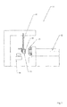
- FIG. 1 a detail of a system 10 for encapsulating a handle 12 of a box 14 can be seen, which is transported along a transport path 16, which may be formed by a conveyor belt, and then inserted by means of a handling device 18 in an injection mold 20, in which the handle 12 overmolded becomes.
- the handle 12 may be one which is present in a side wall of the box 14, but may also be a center handle, as exemplified in connection with FIGS Fig. 9 . 13 and 14 is explained.
- the injection molding tool 20 is connected to an extruder 22, via which thermoplastic material which is flowable in a known manner is supplied to the injection molding tool 20 or to nozzles present in it.
- the injection molding tool 20 consists solely of a nozzle part, without requiring the separate closing part required according to the prior art.
- the unit consisting of the injection mold 20 and the extruder 22 can thereby be made compact, so that use at desired locations can be done easily, so it is not absolutely necessary that the injection mold 20 is used where the box itself is injected ,
- this provides the possibility that the molding to be encapsulated or to be sprayed can protrude to a considerable extent over the nozzle part, since a disability is not given by a closing part.
- a problem-free removal of the molded part from the injection mold 20 can also take place since, as mentioned, a closing part does not have to be previously spaced from the nozzle part in order to be able to remove the molded part from the injection mold.
- FIG. 2 is to take a plan view of a system 24 comprising a plurality of injection molds 26, 28, 30 with associated extruders 32, 34, 36, with which boxes 38, 40, 42 are to be encapsulated in the required extent.
- About handling devices 44, 46, 48, the boxes 38, 40, 42 are inserted into the tools 26, 28, 30 and removed.
- the boxes 38, 40, 42 via a Conveyor belt 50 in the required position between the respective handling device 44, 46, 48 and the associated tool 26, 28, 30 moves.
- Fig. 3 is a detail of Annex 10 or 24 refer to. It can be seen on a conveyor belt 52 arranged boxes 54, 56 to be overmolded. In this case, the outer handles 58, 60, middle handles, not shown, or wall sections such as in particular inner wall sections can be encapsulated.
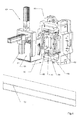
- a handling device 62 which, starting from a pivotable arm 64, comprises a base plate 66 with support posts 68, 70, 72, 74 emanating therefrom, which can be inserted into the corner posts of the box are. Furthermore, the handling device 62 has mutually adjustable side arms 76, 78 to laterally engage the box 56.
- the tool 80 has largely a classic structure with a mold carrier 82 and mold jaws, between which a portion of the box 46 can be introduced to partially surround the portion to be encapsulated by a cavity in the flowable for encapsulation thermoplastic material via a nozzle, not shown is injected.
- a mold carrier 82 and mold jaws, between which a portion of the box 46 can be introduced to partially surround the portion to be encapsulated by a cavity in the flowable for encapsulation thermoplastic material via a nozzle, not shown is injected.
- two corresponding mold jaws in Fig. 4 designated by the reference numerals 84, 86.
- the mold jaws 84, 86 To close the mold jaws 84, 86 and hold or open, ie move away from each other, the mold jaws 84, 86 cooperate with locking wedges 88, 90, are held over the mold jaws 84, 86 in the spray position.
- a closing part is assigned to the nozzle part, via which the locking wedges 88, 90 are locked
- locking takes place without a closing part, resulting in a very compact structural unit for the tool 80.
- the locking or rather locking the mold jaws 84, 86 is technically realized by the fact that the locking wedges 88, 90 in the injection position, ie with closed mold jaws 84, 86 rest on the outside of the forming jaws 84, 86, as in connection with the FIGS. 10 and 11 is explained in more detail.
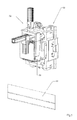
- FIG. 7 is a schematic view of a section of an injection mold to remove to encase inner wall areas of boxes.
- a mold carrier 92 according to the principal explanations according to the Fig. 4
- Form jaws and associated locking wedges which are exemplified by the reference numerals 94, 96 for the mold jaws and 98, 100 for the locking wedges.
- the mold jaws 94, 96 cooperate in the injection position, ie in the closed mold, in a self-locking manner with the associated locking wedges 98, 100, so that a locking takes place exclusively via the nozzle part of the injection molding tool without the need for a closing part.
- Fig. 8 is shown a section of a tool with which a center handle of a box is overmoulded.
- only two mold jaws 102 and these associated locking wedges 104 are required, which in turn along guide blocks 106, 108 are adjustable to the required movement perpendicular to a the mold jaws 102 and the locking wedges 104 receiving mold carrier 110 spanned level to open or close and locking the mold jaws 102 to adjust.
- a tool 112 which also includes only a nozzle part in which existing handles are to be encapsulated in the side walls of a box.
- the tool 112, that is, the nozzle part comprises a mold carrier 114 with locking wedges which are adjustable perpendicular to the plane which is clamped in front of the latter and by way of which the handles or mold jaws receiving on these adjoining regions of the box are adjustable.
- the guide of the locking wedges 120 takes on an outer wall portion of the mold carrier, ie with respect to the locking wedge 120 of the right wall portion 124 of the mold carrier 114.
- the inner locking wedges 122 are guided by guide jaws, not shown, which may also be sections of the bottom wall 114 of the mold carrier.
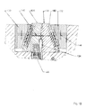
- a section of a nozzle part of an injection mold is shown. It can be seen two mutually adjustable mold jaws 126, 128 and associated therewith locking wedges 130, 132. The directions of movement of the forming jaws 126, 128 and the locking wedges 130, 132 are symbolized by the double arrows.
- the Fig. 10 In closed position, the Fig. 10 can be seen, are the mold jaws 126, 128 on an inner surface to each other and enclose a cavity 134 in which a portion of the box 54, 56 to be encapsulated is introduced, in the embodiment of the Fig. 10 a side handle.
- the cavity 134 surrounds the side handle in regions spaced so as to overmold remaining cavity with the supplied via a nozzle 136 thermoplastic. This is in particular a softer material compared to the material of the box in order to achieve comfortable wearing properties.
- the locking wedges 130, 132 rest on the outer surfaces of the mold jaws 126, 128 in a self-locking manner. This is the clipping of the Fig. 11 to take closer.
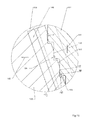
- Fig. 11 is a section of in Fig. 10 shown on the right mold jaw 128 and the associated associated locking wedge 132.
- the mold jaw 128 and the locking wedge 132 are in the closed position over surfaces 134 and 136 self-locking, so that when injecting the plastic material, a pressing apart of the mold jaws 126, 128 is prevented without a separate closing part - as in conventional injection molds - is required.
- the boundary surfaces 134, 136 have a kind of sawtooth structure. This can be realized by successive areas of first, second and third sections.
- a second section 142 extends along the adjustment direction (double arrow 144) of the locking wedge 132.
- a third section 146 which extends extends along a plane which is spanned by the respective surface 134 and 136 of the locking wedge 32 and the form of jaw 128 in the middle, so the overall course of the surface 134 and 136 corresponds. It then joins areas with corresponding sections 138, 142, 146 to form the tooth structure of the surface 136.
- a corresponding structure has the surface 134 of the mold jaw 128, but with superimposed surfaces 134, 136, the first sections 138, 139 and the third Sections 146, 147 spaced from each other.
- the second sections 142, 143 are adjacent to one another in sections.
- self-locking is achieved in the closed position by the second sections 142, 143, wherein the second section 142, 143 does not necessarily have to run parallel to the adjustment direction 144 of the locking wedge 132, but may include an angle ⁇ to the latter, but smaller than 6 °, especially in the range between 5 and 6 °.
- the locking wedge 132 - and thus also the locking wedge 130 - causes not only the locking of the mold jaws 126, 128, but also their movement, ie the moving apart (double arrow 140).
- the locking wedge 132 engages with a cut-T-shaped driver 148 in a corresponding in section T-shaped recesses 150 of the mold jaw 128, as the cutout in Fig. 11a can be seen.
- T-shaped driver 148 is arranged with play in the receptacle 150 so that the opening of the tool initially an adjustment of the locking wedges 130, 132 takes place in the direction of the double arrow 144 without the mold jaws 126, 128 are taken immediately. Only when the driver 148 rests with its transverse leg 152 on the associated locking wedge-side inner surface 154 of the recess 150, the mold jaws 126, 128 are moved along the double arrow 140, whereby the mold can be opened and thus the box or the overmolded handle can be removed.
- the driver 148 is strip-shaped and extends parallel to the averaged from the sections 138, 139, 142, 143, 146, 147 surfaces 134, 136th
- a further embodiment of the teaching of the invention will be explained.
- a second injection tool 158 consisting of a nozzle member 160 and a closure member 162 is provided, with which the box itself is injected.
- the box is inserted by means of a handling device, not shown, in the tool 157, for example, to overmold a center handle.
- the second tool 158 can thereby have a conventional construction to inject boxes so that it does not require further action.
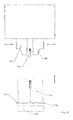
- a lifting device 172 is provided, via which the box 170 is raised or lowered.
- the lifting device 172 in this case comprises a plate-shaped portion 174, on which the box 170 is positioned.
- the lifting device 172 runs between conveyor belts that terminate at a distance from each other, wherein the portion 174 closes the intermediate space when the box 170 is lowered. This provides the possibility that the box 170 is transferred from the plate 174 to an adjacent conveyor belt by the transport of boxes of the other conveyor belt.
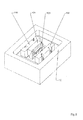
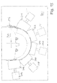
- the molded part 196 is a wheel arch, ie a motor vehicle part.
- the injection molding tool has a nozzle part 200, from which mold jaws and locking elements to be described in more detail below, without the need for a separate and separable closing part which can be adjusted to the nozzle part 200.
- the nozzle part 200 has a mold carrier 202 on which a mold core 204 formed as a stationary mold jaw is arranged, the outer contour of which corresponds to the inner contour of the wheel arch shell 196 to the extent that the area to which the rim 198 is to be injection-molded is positively connected between the contour ram 204 and adjustable to the contour contour mold jaws 206, 208, 210, 212, 214 is received. In doing so, the in Fig.
- the edge 198 is molded onto the molding 196.
- the edge 198 is not only molded butt-shaped to the portion 197 of the wheel arch 196, but extends in sections overlapping the adjacent longitudinal side edges of the portion 197, as in principle the Fig. 18 can be seen.
- piston-cylinder units 216, 218, 220, 222, 224 which are preferably operated hydraulically.
- the mold jaws 206, 208, 210, 212, 214 are arranged in a quasi-star shape around the contoured core 204 and adjustable relative thereto, wherein in the closed position (FIG. Fig. 15 . 16 . 17 . 18 ), the molding jaws 206, 208, 210, 212, 214 in their cavity side extending portions flush with each other, so that plastic from the cavity 215 can not escape.
- each mold jaw 206, 208, 210, 212, 214 is associated with a locking element 226 in the form of a slide, which is also adjustable via a piston-cylinder arrangement 228, wherein preferably a hydraulic cylinder is used.
- the slider or locking piston 226 has at its free end a cuboid to the free end face tapered locking portion which at in Injection position located mold jaw 206, 208, 210, 212, 214 engages positively in a corresponding recess 230.
- the arrangement of the contoured core 204 and the mold jaws 206, 208, 210, 212, 214 and the locking piston 226 which are adjustable with respect to this ensures that, even if the pressure in the piston-cylinder units 216, 218, 220, 222, 224, 228 in FIG Incident should fall, the mold jaws 206, 208, 210, 212, 214 remain locked in the spray position, since the locking piston 226 by gravity in the recesses 230 of the mold blocks 206, 208, 210, 212, 214 remain.
- Fig. 19 is the nozzle member 200 with the tool open, so to the contour core 204 spaced mold jaws 206, 208, 210, 212, 214 shown. In this position, the locking piston 226 is retracted, so that a free movement of the molding jaws 206, 208, 210, 212, 214 is made possible.
Abstract
Description
Die Erfindung bezieht sich auf ein Spritzgießwerkzeug mit einem Düsenteil, das zumindest zwei zueinander verstellbare Formbacken umfasst, die in Spritzstellung einen Hohlraum begrenzen, in dem ein Spritzkanal mündet, sowie mit den Formbacken wechselwirkenden Schließelementen zum Halten der Formbacken in der Spritzstellung. Insbesondere bezieht sich die Erfindung auf ein Spritzgießwerkzeug mit einem Düsenteil, das zumindest zwei relativ zueinander verstellbare Formbacken umfasst, die in Spritzstellung einen Hohlraum begrenzen, in dem ein Spritzkanal mündet, sowie zumindest ein mit zumindest einer auf dem Düsenteil verstellbar angeordneten Formbacke wechselwirkendes Schließelement zum Zuhalten der Formbacken in der Spritzstellung. Ferner nimmt die Erfindung Bezug auf eine Anlage zum Umspritzen eines Abschnitts eines Formteils und/oder zum Anspritzen eines Abschnitts an ein Formteil mit einem Spritzgießwerkzeug. Schließlich nimmt die Erfindung Bezug auf ein Verfahren zum Anspritzen eines Abschnitts an ein Formteil und/oder Umspritzen eines Abschnitts eines Formteils durch Spritzgießen, wobei das Formteil abschnittsweise in einen von zueinander verstellbaren von einem Düsenteil eines Spritzgießwerkzeuges ausgehenden Formbacken umgebenen Hohlraum eingebracht wird, in den nach Schließen der Formbacken schmelzflüssiges Material gespritzt wird.The invention relates to an injection mold having a nozzle part which comprises at least two mutually adjustable mold jaws which delimit a cavity in the injection position, in which an injection channel opens, and with the mold jaws interacting closing elements for holding the mold jaws in the injection position. In particular, the invention relates to an injection mold having a nozzle part which comprises at least two mold jaws which are adjustable relative to one another and which delimit a cavity in the injection position in which an injection channel opens, and at least one closing element interacting with at least one mold jaw which is adjustably arranged on the nozzle part the mold jaws in the spray position. Furthermore, the invention relates to a system for encapsulating a portion of a molded part and / or for injecting a portion of a molding with an injection mold. Finally, the invention relates to a method for injection molding a portion of a molded part and / or molding a portion of a molded part by injection molding, wherein the molded part is partially introduced into one of mutually adjustable by a nozzle part of an injection mold outgoing mold cavity surrounded cavity in the after Close the mold jaws molten material is injected.
Aus der
Der
Ein aus einem Düsenteil und einem Schließteil bestehendes Spritzgießwerkzeug ist der
Ein aus Düsenteil und Schließteil bestehendes Werkzeug ist auch aus der
Bei einem Flachenkasten aus Kunststoff nach der
Um ein Spritzgussteil herzustellen, sieht die
Nach der
Zum Spritzgießen von Kunststoffteilen nach der
Ein Spritzgießwerkzeug nach der
In der DE.Z.:
Der vorliegenden Erfindung liegt das Problem zu Grunde, ein Spritzgießwerkzeug der eingangs genannten Art sowie eine Anlage unter Einbeziehung eines entsprechenden Spritzgießwerkzeugs sowie ein Verfahren derart weiterzubilden, dass bei kompakter Bauart problemlos ein Formteil wie Kasten oder Kraftfahrzeugteil wie Radlaufschale zumindest bereichsweise umspritzt werden kann, um in diesem Bereich gewünschte Materialeigenschaften zu erzielen bzw. das Formteil in einen oder mehreren gewünschten Bereichen geometrisch zu verändern wie zu verlängern. Dabei soll auch ein Einsatz unabhängig vom Ort der Herstellung des Formteils selbst möglich sein.The present invention is based on the problem of developing an injection mold of the type mentioned above and a system involving a corresponding injection mold and a method such that in a compact design easily a molding such as box or motor vehicle part such as wheel arch can be at least partially encapsulated in order To achieve desired material properties in this area or to change the shape of geometric shape in one or more desired areas as extend. It should also be an application regardless of the place of manufacture of the molding itself possible.
Erfindungsgemäß wird das Problem im Wesentlichen gelöst durch ein Spritzgießwerkzeug mit einem Düsenteil, das zumindest zwei relativ zueinander verstellbare Formbacken umfasst, die in Spritzstellung einen Hohlraum begrenzen, in dem ein Spritzkanal mündet, sowie zumindest ein mit zumindest einer auf dem Düsenteil verstellbar angeordneten Formbacke wechselwirkendes Verriegelungs- oder Schließelement zum Zuhalten der Formbacken in der Spritzstellung, wobei das zumindest eine Verriegelungs- oder Schließelement von dem Düsenteil ausgeht, zu diesem verstellbar ausgebildet ist und die zumindest eine Formbacke in ihrer Spritzstellung verriegelt und wobei eine Formbacke ein Konturkern ist, das sich dadurch auszeichnet, dass die den Konturkern bildende Formbacke stationär von einem Formträger des Düsenteils ausgeht, dass zu dem Konturkern zumindest eine Formbacke verstellbar angeordnet ist und dass das Verriegelungs- oder Schließelement in Schließstellung der Konturbacke formschlüssig mit der zumindest einen Formbacke verbunden ist.According to the invention, the problem is essentially solved by an injection mold having a nozzle part which comprises at least two mold jaws which are adjustable relative to one another and which delimit a cavity in the injection position in which an injection channel opens, and at least one interlock which interacts with at least one mold jaw adjustably arranged on the nozzle part - Or closing element for locking the mold jaws in the spray position, wherein the at least one locking or closing element emanating from the nozzle part, is designed to be adjustable and locked at least one mold jaw in its injection position and wherein a shaping jaw is a contour core, which is characterized in that the shaping jaw forming the contour core proceeds stationarily from a mold carrier of the nozzle part such that at least one shaping jaw is adjustably arranged relative to the contour core and that the locking mechanism or closing element in the closed position of the contour of the contour block is positively connected to the at least one mold block.
Auch sieht eine Lösung ein Verfahren vor zum Anspritzen eines Abschnitts an ein Formteil und/oder Umspritzen eines Abschnitts eines Formteils, wie Kraftfahrzeugteil, insbesondere Radlaufschale oder Unterboden, wobei das Formteil abschnittsweise in einen von relativ zueinander verstellbaren von einem Düsenteil eines Spritzgießwerkzeuges ausgehenden Formbacken umgebenen Hohlraum eingebracht wird, zumindest eine der Formbacken mittels zumindest eines von dem Düsenteil ausgehenden Schließelements durch Verstellen dieses zu der zumindest einen Formbacke in ihrer Spritzstellung verriegelt wird und in den Hohlraum nach Schließen der Formbacken (Spritzstellung) fließfähiges Material gespritzt wird, das sich dadurch auszeichnet, dass das Formteil auf einer der als stationärer auf einen Formträger des Düsenteils angeordneter Formkern ausgebildeten Formbacke angeordnet wird, zumindest eine Formbacke zu dem Formkern zum Ausbilden des Hohlraums verstellt wird und sodann die zumindest eine zu dem Formkern durch formschlüssiges Eingreifen des Verriegelungs- oder Schließelementes verriegelt wird.Also, a solution provides a method for injecting a portion of a molded part and / or molding a portion of a molded part, such as motor vehicle part, in particular wheel arch or subfloor, wherein the molded part in sections in one of relatively adjustable from a nozzle part of an injection mold outgoing mold cavity surrounded cavity is introduced, at least one of the mold jaws is locked by means of at least one outgoing from the nozzle member closing element by adjusting this to the at least one mold jaw in its injection position and in the cavity after closing the mold jaws (injection position) flowable material is injected, which is characterized in that the mold part is arranged on one of the mold jaws designed as a stationary mold jaw arranged on a mold carrier of the nozzle part, at least one mold jaw is adjusted to the mold core for forming the cavity, and then the at least one e is locked to the mandrel by positive engagement of the locking or closing element.
Weiterbildungen ergeben sich aus den jeweiligen abhängigen Ansprüchen.Further developments emerge from the respective dependent claims.
Abweichend von vorbekannten Spritzgießwerkzeugen wird erfindungsgemäß ein solches vorgeschlagen, bei dem kein gesondertes zu dem Düsenteil verstellbares Schließteil erforderlich ist, um die Formbacken während des Spritzens zu sichern, also zuzuhalten. Somit ist das Düsenteil während des Spritzens von einem Schließteil nicht abgedeckt, so dass problemlos ein Abschnitt des Formteils umspritzt bzw. ein Abschnitt an das Formteil angespritzt werden kann. Bei dem Formteil kann es sich z. B. um einen Kasten oder ein Kraftfahrzeugteil wie Radlaufschale oder einen Unterboden handeln, so dass das Formteil in erheblichem Umfang aus dem Werkzeug vorsteht, eine Möglichkeit, die klassische Spritzgießwerkzeuge nicht bieten, bei denen die von dem Düsenteil ausgehenden Formbacken über ein gesondertes zu den Formbacken verstellbares Düsenteil verriegelt werden. Zum Entfernen des hergestellten Spritzgussteils muss das Schließteil zu dem Düsenteil in einem Umfang beabstandet werden, dass das Formteil aus dem Zwischenraum zwischen Düsenteil und Schließteil entfernt werden kann. Hierzu müssen Düsenteil und Schließteil axial derart zueinander beabstandet werden, dass der lichte Abstand größer als Erstreckung des Spritzgussteils in axialer Richtung ist.Notwithstanding prior art injection molds according to the invention, such is proposed in which no separate adjustable to the nozzle part closing member is required to secure the mold jaws during spraying, so zuhalten. Thus, the nozzle part is not covered during the spraying of a closing part, so that a part of the molded part can be molded around easily or a section can be molded onto the molded part. In the molding, it may be z. B. to act a box or a motor vehicle part such as wheel arch or an underbody, so that the molding projecting to a considerable extent from the tool, a way that classic injection molds do not offer, where the outgoing from the nozzle part mold jaws on a separate to the mold jaws adjustable nozzle part are locked. To remove the manufactured injection-molded part, the closing part must be spaced from the nozzle part to an extent that the molded part can be removed from the space between the nozzle part and closing part. For this purpose, the nozzle part and closing part must be axially spaced from each other such that the clear distance is greater than the extension of the injection-molded part in the axial direction.
Erfindungsgemäß geht von dem Düsenteil selbst das zum Zuhalten des bzw. der Formbacken erforderliche verstellbare Schließelement aus, so dass ein überaus kompaktes Spritzgießwerkzeug zur Verfügung gestellt wird, das folglich ohne großen maschinellen Aufwand dort zum Einsatz gelangen kann, wo z. B. ein Abschnitt eines Formteils wie Kastens umspritzt werden soll. Insbesondere besteht erwähntermaßen der Vorteil, dass das zu umspritzende bzw. anzuspritzende Formteil in erheblichem Umfang über das Düsenteil vorstehen kann.According to the invention goes from the nozzle member itself to hold the mold or the jaws required adjustable closing element, so that a very compact injection mold is provided, which can thus be used there without great mechanical effort, where z. B. a portion of a molded part such as boxes to be encapsulated. In particular, there is the advantage, as mentioned, that the molded part to be overmolded or molded can project to a considerable extent over the nozzle part.
Selbstverständlich beschränkt sich die erfindungsgemäße Lehre nicht allein auf ein Spritzgießwerkzeug, mit dem ein Formteil bzw. ein Abschnitt eines solchen umspritzt bzw. ein Abschnitt aufgespritzt werden kann. Vielmehr ist die Lehre auch prinzipiell zum Spritzen von Formteilen an sich geeignet.Of course, the teaching of the invention is not limited solely to an injection mold with which a molded part or a portion of such a molded or a section can be sprayed. Rather, the teaching is also suitable in principle for spraying molded parts per se.
In Weiterbildung der Erfindung ist vorgesehen, dass die Formbacke mit zumindest einen Schließelement in Form eines Verriegelungskeils wechselwirkt, wobei die Formbacke und der Verriegelungskeil in Schließstellung über geneigt zum Verstellweg des Verriegelungskeils verlaufende strukturierte Flächen kraft- und formschlüssig verbunden sind, um auf diese Weise die Selbsthemmung zu realisieren. Dabei weisen die aufeinander liegenden Flächen insbesondere eine sägezahnförmige Geometrie auf.In a further development of the invention, it is provided that the shaping jaw interacts with at least one closing element in the form of a locking wedge, the forming jaw and the locking wedge being positively and non-positively connected in the closed position via inclined inclined surfaces to the adjustment path of the locking wedge in order to prevent self-locking in this manner to realize. In particular, the surfaces lying on one another have a sawtooth-shaped geometry.
Vorzugsweise weist die Fläche mehrere zumindest einen ersten, einen zweiten und einen dritten Abschnitt umfassende Bereiche auf, wobei sich der erste Abschnitt quer zum Verstellweg des Verriegelungskeils, der zweite Abschnitt sich in Richtung des Verstellwegs des Verriegelungskeils und der die Abschnitte verbindende dritte Abschnitt entlang von von der strukturierten Fläche aufgespannter Ebene erstrecken. Durch eine diesbezügliche Geometrie ist sichergestellt, dass in der Schließstellung die aufeinander liegenden Flächen von Formbacke und Verriegelungskeil derart zueinander abgestützt sind, dass die erforderliche Selbsthemmung mit der Folge auftritt, dass beim Spritzen ein Auseinanderbewegen der Formbacken ausgeschlossen ist.Preferably, the surface has a plurality of at least a first, a second and a third portion comprising areas, wherein the first portion transverse to the displacement of the locking wedge, the second portion in the direction of the displacement of the locking wedge and connecting the sections third section along extend the structured surface spanned plane. By a related geometry is ensured that in the closed position, the superposed surfaces of the mold jaw and locking wedge supported each other in such a way are that the required self-locking occurs with the result that a dislocation of the mold jaws is excluded during spraying.
Dabei kann die Reihenfolge der Abschnitte auch voneinander abweichen. Ferner verlaufen die ersten und dritten Abschnitte der aufeinander liegenden Flächen von Verriegelungskeil und Formbacke stets zueinander beabstandet.The order of the sections may differ. Further, the first and third portions of the superimposed surfaces of locking wedge and form jaw are always spaced from each other.
Verlaufen die zweiten Abschnitte der die sägezahnförmige Geometrie bildenden Bereiche der sich aufeinander abstützenden Flächen von Formbacke und Verriegelungskeil vorzugsweise parallel zum Verstellweg des Verriegelungskeils, so kann der zweite Abschnitt auch zum Verstellweg einen Winkel α mit insbesondere α ≤ 6°, vorzugsweise 5° ≤ α ≤ 6° einschließen.If the second sections of the areas forming the sawtooth-shaped geometry of the surfaces of the shaping jaw and the locking wedge are preferably parallel to the adjustment path of the locking wedge, the second section can also be an angle α to the adjustment path, in particular α ≦ 6 °, preferably 5 ° ≦ α ≦ Enclose 6 °.
Um über den Verriegelungskeil die Formbacken beim Öffnen des Werkzeugs mitzunehmen, ist vorgesehen, dass von dem Verriegelungskeil zumindest ein in die Formbacke eingreifender Mitnehmer ausgeht, wobei zum Entriegeln der Formbacke der Verriegelungskeil zu dieser mit Spiel verstellbar ist. Mit anderen Worten erfolgt zunächst ein Bewegen des Verriegelungskeils, um sodann die Formbacke mitzunehmen. Hierdurch ist sichergestellt, dass beim Schließen des Verriegelungskeils der erforderliche Formschluss zur Formbacke erreichbar ist.In order to take over the locking jaw the mold jaws when opening the tool, it is provided that at least one engaging in the mold jaw driver starts from the locking wedge, wherein for unlocking the jaw of the locking wedge is adjustable with this game. In other words, a first movement of the locking wedge, in order then to take along the mold jaw. This ensures that when closing the locking wedge of the required form fit to the jaw is reached.
Insbesondere geht von dem Verriegelungskeil ein entlang dessen mit der Formbacke wechselwirkender Fläche verlaufender im Schnitt T-förmiger Mitnehmer aus, dessen Querschenkel mit Spiel in eine in Längsrichtung der mit dem Verriegelungskeil wechselwirkenden Fläche verlaufende Aussparung eingreift.In particular, starting from the locking wedge along its interacting with the mold jaw surface extending in the cut T-shaped driver whose transverse leg engages with play in a longitudinal direction of the interacting with the locking wedge recess.
Mit anderen Worten weist die Formbacke in ihrem dem Verriegelungskeil zugewandten Bereich eine im Schnitt T-förmige Aussparung auf, in die mit Spiel der T-förmigen Mitnehmer verläuft.In other words, the shaping jaw has, in its region facing the locking wedge, a cut in the form of a T-shaped recess into which the T-shaped driver runs with play.
Der von den Formbacken umgebene Hohlraum zum Umspritzen eines Abschnitts eines Formteils ist des Weiteren derart ausgebildet, dass der Hohlraum zumindest abschnittsweise beabstandet den zu umspritzenden Abschnitt umgibt. Gegebenenfalls kann der Hohlraum auch umlaufend den Abschnitt beabstandet umgeben.The cavity surrounded by the mold jaws for encapsulating a portion of a molded part is further designed such that the cavity is at least partially spaced surrounds the portion to be overmoulded. Optionally, the cavity may also circumferentially surround the portion spaced.
Soll ein Abschnitt an ein Formteil angespritzt werden, so ist die Erstreckung des Bereichs des Formteils innerhalb des Hohlraums, an den der Abschnitt angespritzt werden soll, häufig erheblich kleiner als der verbleibende Raum, in den das schmelzflüssige Material gespritzt wird.When a portion is to be molded onto a molding, the extent of the portion of the molding within the cavity to which the portion is to be molded is often considerably smaller than the remaining space into which the molten material is injected.
Unabhängig hiervon besteht die Möglichkeit, problemlos Verstärkungen an vorhandene Formteile anzuspritzen bzw. Griffe wie Griffe von Kästen zu erneuern bzw. mit einer Oberfläche bzw. Außenschicht zu versehen, die den Tragekomfort erhöht.Regardless of this, it is possible to easily inject reinforcements on existing moldings or to renew handles such as handles of boxes or provided with a surface or outer layer, which increases the comfort.
Insbesondere ist vorgesehen, dass von dem Formträger des Düsenteils ein eine stationäre Formbacke bildender Konturkern ausgeht, dass zu dem Konturkern zumindest eine Formbacke vorzugsweise über einen ersten mit dem Formträger verbundenen Druckzylinder verstellbar angeordnet ist, dass von dem Formträger das zumindest eine vorzugsweise über einen mit dem Formträger verbundenen zweiten Druckzylinder verstellbares Verriegelungselement ausgeht, das in Schließstellung der Konturbacke formschlüssig mit der Formbacke verbunden ist und vorzugsweise in eine Ausnehmung der Formbacke eingreift. Dabei kann der Verstellweg der Formbacke quer, insbesondere senkrecht zum Verstellweg des Verriegelungselementes verlaufen.In particular, it is provided that from the mold carrier of the nozzle part forming a stationary mold jaw contour core emanates that the contour core at least one mold jaw is preferably adjustably arranged via a first pressure cylinder connected to the mold carrier that of the mold carrier, the at least one preferably via a with the Mold support associated second pressure cylinder adjustable locking element goes out, which is positively connected in the closed position of the contour rake with the forming jaw and preferably engages in a recess of the mold jaw. In this case, the adjustment path of the shaping jaw can run transversely, in particular perpendicular to the adjustment path of the locking element.
Durch die erfindungsgemäße Lehre besteht mit konstruktiv einfachen Maßnahmen die Möglichkeit, auch an großen Formteilen Abschnitte anzuspritzen bzw. Abschnitte des Formteils selbst zu umspritzen. Dabei kann das an- bzw. zu umspritzende Formteil auf einen als stationäre Formbacke zu bezeichnenden Konturkern positioniert werden, zu dem mehrere Formbacken verstellbar sind, die ihrerseits in Schließstellung zusammen einen Formhohlraum außenseitig verschließen.The teaching according to the invention, with structurally simple measures, makes it possible to inject portions even on large shaped parts or to overmold sections of the molded part itself. In this case, the molded part to be molded on or around can be positioned on a contoured core to be designated as a stationary mold jaw, to which a plurality of mold jaws are adjustable, which in turn close a mold cavity in the closed position on the outside.
So können die verstellbaren Formbacken sternförmig um einen Konturkern angeordnet werden, wobei die Formbacken in Schließstellung bündig in dem Bereich ineinander übergehen, in dem der Formhohlraum begrenzt wird.Thus, the adjustable mold jaws can be arranged in a star shape around a contour core, wherein the mold jaws in the closed position flush in the area merge into each other, in which the mold cavity is limited.
Das Verstellen der Konturbacken kann dabei über Druck- wie Hydraulikzylinder erfolgen, die von dem Düsenteil, d. h. dessen Formträger ausgehen.The adjustment of the contour ridges can be done via pressure as hydraulic cylinder, which depends on the nozzle part, d. H. whose mold carriers go out.
Um die Formbacken in der Spritzstellung zu verriegeln, ist jeder Formbacke ein Verriegelungselement zugeordnet, das insbesondere formschlüssig in eine Ausnehmung der Formbacke eingreift. Dabei verlaufen Verstellweg einer jeden Formbacke zum Verstellweg des zugeordneten Verriegelungselementes vorzugsweise senkrecht zueinander. Der Verstellweg der Formbacke kann dabei parallel zur von dem Formträger aufgespannten Ebene verlaufen, wohingegen der Verstellweg des Verrieglungselementes sich senkrecht zu der Ebene erstreckt. Insbesondere ist das Verriegelungselement mit dem diesen verstellbaren Druckzylinder in den Formträger eingelassen.To lock the mold jaws in the injection position, each mold jaw is associated with a locking element which engages in particular a form-fitting manner in a recess of the mold jaw. In this case, adjustment of each mold jaw to the adjustment of the associated locking element preferably perpendicular to each other. The adjustment path of the shaping jaw can run parallel to the plane spanned by the mold carrier, whereas the adjustment path of the locking element extends perpendicular to the plane. In particular, the locking element is embedded with this adjustable pressure cylinder in the mold carrier.
Unter Eingreifen in die Formbacken ist auch ein Wechselwirken mit dem Kolben oder einem sonstigen mit der Formbacke mitbewegbares Element zu verstehen.Intervention in the mold jaws also means interacting with the piston or another element which can be moved with the mold jaw.
Eine Anlage zum Umspritzen eines Abschnitts eines kastenförmigen Formteils mit in diesem vorhandenen Holmen, wobei der Abschnitt in den Hohlraum des Spritzgießwerkzeugs zuvor beschriebener Art einsetzbar ist, zeichnet sich dadurch aus, dass die Anlage zumindest eine das kastenförmige Formteil aufnehmende Fördereinrichtung sowie zumindest eine das kastenförmige Formteil erfassende und in das Spritzgießwerkzeug einsetzende bzw. aus diesem entnehmende Handhabungseinrichtung umfasst, die Stützholme aufweist, die in die Holme des kastenförmigen Formteils eingreifen.A system for encapsulating a portion of a box-shaped molding with existing in this Holmen, the portion is inserted into the cavity of the injection mold of the type described above, characterized in that the system at least one box-shaped molding receiving conveyor and at least one box-shaped molding comprises grasping and inserting into the injection mold or removing therefrom handling device having the support struts which engage in the spars of the box-shaped molding.
Erfindungsgemäß wird das zu umspritzende kastenförmige Formteil wie Flaschenkasten mit einer Fördereinrichtung wie Förderband zum Spritzgießwerkzeug transportiert, um sodann von der Handhabungseinrichtung erfasst zu werden. Dabei greifen von der Handhabungseinrichtung ausgehende Stützholme in die entsprechenden Holme des kastenförmigen Formteils ein, so dass beim Spritzen eine unzulässige Verformung ausgeschlossen ist. Gleichzeitig dienen die in die Holme eingreifenden Stützholme zum Erfassen des kastenförmigen Formteils.According to the invention, the box-shaped molded part to be encapsulated, such as a bottle crate, is transported to the injection molding tool by means of a conveying device, such as a conveyor belt, in order then to be gripped by the handling device. In this case, outgoing from the handling device support beams in the corresponding spars of the box-shaped molding, so that when spraying an impermissible deformation is excluded. At the same time, the supporting spars engaging in the spars serve to grasp the box-shaped molding.
In Weiterbildung der Erfindung ist vorgesehen, dass die Anlage zumindest zwei fluchtend zueinander ausgerichtete und im Bereich des Spritzgießwerkzeugs über einen Zwischenraum zueinander beabstandete Fördereinrichtungen umfasst, dass der Zwischenraum von einer Aufnahme verschließbar ist, mit der das Formteil an das Spritzgießwerkzeug übergebbar bzw. von diesem entnehmbar ist, und dass das Formteil bei durch die Aufnahme verschlossenen Zwischenraum über diesen mittels von einer der Fördereinrichtungen transportierten weiteren Formteilen schiebbar ist.In a further development of the invention it is provided that the system comprises at least two mutually aligned and in the region of the injection molding over a gap spaced apart conveyors, that the gap is closed by a receptacle with which the molded part can be transferred to the injection mold or removed from this is, and that the molded part is closed by closed by the recording space on this by means of one of the conveyors transported further molded parts.
Durch diese Ausgestaltung ist mit konstruktiv einfachen Maßnahmen das teilweise zu umspritzende Formteil auf das Spritzgießwerkzeug ausrichtbar, um sodann das Formteil mittels der die Funktion einer Handhabungseinrichtung ausübenden Aufnahme das Formteil an das Spritzgießwerkzeug zu übergeben bzw. aus diesem zu entnehmen. Dabei kann die Aufnahme vorzugsweise als Hubeinrichtung wie Hubtisch ausgebildet sein, so dass folglich das Spritzgießwerkzeug senkrecht oberhalb des Förderwegs des Formteils angeordnet ist.As a result of this configuration, the molded part, which is partly to be encapsulated, can be aligned with the injection mold with structurally simple measures in order then to transfer the molded part to the injection molding tool by means of the receptacle performing the function of a handling device or to remove it therefrom. In this case, the receptacle may preferably be designed as a lifting device such as lifting table, so that consequently the injection mold is arranged vertically above the conveying path of the molded part.
Nach einem weiteren Vorschlag der Erfindung ist vorgesehen, dass das Spritzgießwerkzeug von einer Halterplatte ausgeht, von der ein ein Düsenteil sowie ein Schließteil aufweisendes zweites Spritzgießwerkzeug ausgeht, mittels dessen das Formteil selbst gespritzt wird. Über das Schließteil werden in gewohnter Weise die Formbacken in dem Düsenteil verriegelt bzw. freigegeben. Dabei wird das Formteil in das Düsenteil des ersten Spritzgießwerkzeugs über eine Handhabungseinrichtung übergeben.According to a further proposal of the invention, it is provided that the injection molding tool starts from a holder plate, from which a second injection molding tool having a nozzle part and a closing part emanates, by means of which the molded part itself is injected. About the closing part the mold jaws are locked or released in the nozzle part in the usual way. In this case, the molded part is transferred into the nozzle part of the first injection molding tool via a handling device.
Des Weiteren zeichnet sich die Erfindung durch ein Verfahren zum Anspritzen eines Abschnitts an ein Formteil und/oder Umspritzen eines Abschnitts eines Formteil durch Spritzgießen, wobei das Formteil abschnittsweise in einen von zueinander verstellbaren von einem Düsenteil eines Spritzgießwerkzeuges ausgehenden und relativ zueinander verstellbaren Formbacken umgebenen Hohlraum eingebracht wird, in den nach Schließen der Formbacken (Spritzstellung) fließfähiges Material gespritzt wird, dadurch aus, dass zumindest eine der Formbacken mittels zumindest eines von dem Düsenteil ausgehendes Schließelement durch Verstellen dieses zu der zumindest einen Formbacke in ihrer Spritzstellung verriegelt wird, wobei insbesondere vorgesehen ist, dass die Formbacken mittels von dem Düsenteil ausgehender Schließelemente durch Verstellen dieser zu den Formbacken durch Selbsthemmung in ihrer Spritzstellung gehalten werden.Furthermore, the invention is characterized by a method for injecting a portion of a molded part and / or molding a portion of a molded part by injection molding, wherein the molded part partially inserted into one of mutually adjustable from a nozzle part of an injection molding and outgoing and relatively adjustable mold cavity surrounded cavity is, in the after closing of the mold jaws (injection position) flowable material is injected, characterized in that at least one of the mold jaws is locked by means of at least one of the nozzle part outgoing closing element by adjusting this to the at least one mold jaw in its injection position, which is provided in particular that the forming jaws be held by means of the nozzle part outgoing closing elements by adjusting this to the mold jaws by self-locking in their spray position.
Weitere Einzelheiten, Vorteile und Merkmale der Erfindung ergeben sich nicht nur aus den Ansprüchen, den diesen zu entnehmenden Merkmalen - für sich und/oder in Kombination - sondern auch aus der nachfolgenden Beschreibung von der Zeichnung zu entnehmenden bevorzugten Ausführungsbeispiele.Further details, advantages and features of the invention will become apparent not only from the claims, the features to be taken these features - alone and / or in combination - but also from the following description of the drawing to be taken preferred embodiments.
Es zeigen:
- Fig. 1
- einen Seitenansicht einer Anordnung zum Umspritzen eines Abschnitts eines Formteils bzw. Anspritzen eines Abschnitts an ein Formteil,
- Fig. 2
- eine Draufsicht auf eine Anlage zum Umspritzen bzw. Anspritzen von Abschnitten von bzw. an Formteilen,
- Fig. 3
- einen Ausschnitt aus einer Anlage zum Umspritzen bzw. Anspritzen von Abschnitten von bzw. an Formteilen in Form von Kästen,
- Fig. 4
- die Handhabungseinrichtung gemäß
Fig. 3 mit auf ein Spritzgießwerkzeug ausgerichtetem Formteil, - Fig. 5
- das Formteil gemäß
Fig. 4 bei in das Spitzgießwerkzeug eingebrachter Position, - Fig. 6
- das Formteil gemäß
Fig. 4 und5 nach Umspritzen bzw. Anspritzen und Entfernen aus dem Spritzgießwerkzeug. - Fig. 7
- einen Ausschnitt eines Spritzgießwerkzeuges zum Umspritzen einer Innenwandung eines Formteils,
- Fig. 8
- einen Ausschnitt eines Spritzgießwerkzeuges zum Umspritzen eines Mittelhandgriffs eines Formteils,
- Fig. 9
- einen Ausschnitt eines Spritzgießwerkzeuges zum Umspritzen von Außenhandgriffen eines Formteils,
- Fig. 10
- einen Ausschnitt einer weiteren Ausführungsform eines Spritzgießwerkzeuges,
- Fig. 11
- einen Ausschnitt aus der Anordnung gemäß
Fig. 10 , - Fig. 12
- eine weitere Ausführungsform einer Anordnung zum Spritzen eines Formteils sowie zum Umspritzen eines Abschnitts des Formteils,
- Fig. 13
- einen Ausschnitt aus einer Anlage zum Umspritzen eines Mittelhandgriffs eines Formteils,
- Fig. 14
- eine perspektivische Darstellung eines Ausschnitts des Werkzeugs gemäß
Fig. 13 , - Fig. 15
- eine Draufsicht auf einen Ausschnitt eines Düsenteils mit an- bzw. umzuspritzenden Formteil,
- Fig. 16
- eine perspektivische Darstellung des Düsenteils gemäß
Fig. 15 , - Fig. 17
- einen Schnitt durch das Düsenteil gemäß
Fig. 15 bzw. 16, - Fig. 18
- einen Ausschnitt aus dem Düsenteil gemäß
Fig. 17 und - Fig. 19
- die Darstellung gemäß
Fig. 17 bei geöffnetem Werkzeug.
- Fig. 1
- a side view of an arrangement for encapsulating a portion of a molding or molding a portion of a molding,
- Fig. 2
- a plan view of a system for overmolding or injection molding of sections of or on molded parts,
- Fig. 3
- a detail of a system for encapsulation or injection molding of sections of or on molded parts in the form of boxes,
- Fig. 4
- the handling device according to
Fig. 3 with a molded part aligned with an injection mold, - Fig. 5
- the molding according to
Fig. 4 when inserted into the injection molding tool position, - Fig. 6
- the molding according to
Fig. 4 and5 after encapsulation or injection and removal from the injection mold. - Fig. 7
- a detail of an injection mold for encapsulating an inner wall of a molded part,
- Fig. 8
- a detail of an injection molding tool for encapsulating a center handle of a molded part,
- Fig. 9
- a detail of an injection mold for encapsulating external handles of a molded part,
- Fig. 10
- a detail of another embodiment of an injection mold,
- Fig. 11
- a section of the arrangement according to
Fig. 10 . - Fig. 12
- a further embodiment of an arrangement for spraying a molded part and for encapsulating a portion of the molded part,
- Fig. 13
- a detail of a system for encapsulating a center handle of a molded part,
- Fig. 14
- a perspective view of a section of the tool according to
Fig. 13 . - Fig. 15
- a plan view of a section of a nozzle part with on or umzuspritzenden molding,
- Fig. 16
- a perspective view of the nozzle part according to
Fig. 15 . - Fig. 17
- a section through the nozzle part according to
Fig. 15 or 16, - Fig. 18
- a section of the nozzle part according to
Fig. 17 and - Fig. 19
- the representation according to
Fig. 17 with the tool open.
Anhand der nachfolgenden Beschreibung der
Als Formteile kommen insbesondere auch Kunststoffteile der Kraftfahrzeugindustrie wie Radlaufschalen oder Kraftfahrzeugunterbodenverkleidungen in Frage, um nur beispielhaft einige Gegenstände zu nennen.In particular, plastic parts of the motor vehicle industry such as wheel arch liners or motor vehicle underbody linings are also suitable as shaped parts, for example only to mention a few items.
Auch wird nachstehend die Erfindung anhand des Umspritzens eines Griffs eines Flaschenkastens erläutert, ohne dass dies als Einschränkung der Erfindung zu verstehen ist. Vielmehr gelten gleiche Erläuterungen für das Anspritzen eines Abschnitts an ein Formteil wie Flaschenkasten.Also, the invention will be explained below with reference to the encapsulation of a handle of a bottle crate, without this being to be understood as limiting the invention. Rather, the same explanations apply to the sprinkling of a section on a molding such as bottle crate.
Der
Bei dem Griff 12 kann es sich um einen solchen handeln, der in einer Seitenwandung des Kastens 14 vorhanden ist, aber auch um einen Mittelhandgriff handeln, wie dies beispielhaft im Zusammenhang mit den
Das Spritzgießwerkzeug 20 ist mit einem Extruder 22 verbunden, über den in bekannter Weise fließfähiger thermoplastischer Kunststoff dem Spritzgießwerkzeug 20 bzw. in diesem vorhandenen Düsen zugeführt wird. Dabei besteht erfindungsgemäß das Spitzgießwerkzeug 20 allein aus einem Düsenteil, ohne dass das nach dem Stand der Technik erforderliche gesonderte Schließteil erforderlich ist. Somit wird die Zuhaltung von Formbacken, die einen Hohlraum begrenzen, in dem ein Abschnitt des Kastens, also im Ausführungsbeispiel ein Griff eingebracht wird, um sodann umspritzt zu werden, über Elemente realisiert, die vom Düsenteil selbst ausgehen. Dies wird an Hand der
Die Einheit bestehend aus dem Spritzgießwerkzeug 20 und dem Extruder 22 kann hierdurch kompakt aufgebaut werden, so dass ein Einsatz an gewünschten Orten problemlos erfolgen kann, es also nicht zwingend erforderlich ist, dass das Spritzgießwerkzeug 20 dort zum Einsatz gelangt, wo der Kasten selbst gespritzt wird.The unit consisting of the
Hierdurch besteht die Möglichkeit, dass zum Beispiel Kästen in einer Flaschenabfüllanlage, von der aus die Flaschen in die Kästen eingesetzt werden, umspritzt werden können, so dass auch ein nachträgliches Umspritzen von bereits im Einsatz befindlichen Kästen möglich ist.This makes it possible that, for example, boxes in a bottling plant, from which the bottles are inserted into the boxes, can be overmolded, so that a subsequent encapsulation of boxes already in use is possible.
Insbesondere ist hierdurch die Möglichkeit gegeben, dass das zu umspritzende bzw. anzuspritzende Formteil in erheblichem Umfang über das Düsenteil vorstehen kann, da eine Behinderung durch ein Schließteil nicht gegeben ist. Auch kann ein problemloses Entfernen des Formteils aus dem Spritzgießwerkzeug 20 erfolgen, da erwähntermaßen ein Schließteil nicht zuvor von dem Düsenteil beabstandet werden muss, um das Formteil aus dem Spritzgießwerkzeug herausnehmen zu können.In particular, this provides the possibility that the molding to be encapsulated or to be sprayed can protrude to a considerable extent over the nozzle part, since a disability is not given by a closing part. A problem-free removal of the molded part from the
Der
Der
Damit der jeweilige Kasten 54, 56 in ein Spritzgießwerkzeug eingesetzt wird, ist eine Handhabungseinrichtung 62 vorgesehen, die von einem verschwenkbaren Arm 64 ausgehend eine Basisplatte 66 mit von diesem ausgehende Stützholmen 68, 70, 72, 74 umfasst, die in die Eckholme des Kastens einsetzbar sind. Ferner weist die Handhabungseinrichtung 62 zueinander verstellbare Seitenarme 76, 78 auf, um den Kasten 56 seitlich zu erfassen.In order for the
Sobald die Holme 68, 72, 74 in die Eckholme des Kastens 56 eingefahren sind, wird der Arm 64 derart verschwenkt, dass der Kasten 56 mit seiner offenen Seite auf ein Werkzeug 80 ausgerichtet und in dieses eingesetzt wird. Das Werkzeug 80 weist weitgehend einen klassischen Aufbau mit einem Formenträger 82 sowie Formbacken auf, zwischen denen ein Abschnitt des Kastens 46 einbringbar ist, um bereichsweise den zu umspritzenden Abschnitt von einem Hohlraum zu umgeben, in den zum Umspritzen fließfähiger thermoplastischer Kunststoff über eine nicht dargestellte Düse eingespritzt wird. Rein beispielhaft werden zwei entsprechende Formbacken in
Um die Formbacken 84, 86 zu schließen und zuzuhalten bzw. zu öffnen, also voneinander weg zu bewegen, wirken die Formbacken 84, 86 mit Verriegelungskeilen 88, 90 zusammen, über die Formbacken 84, 86 in der Spritzstellung zugehalten werden.To close the
Der Formenträger 82 mit den Formbacken 84, 86 und den Verriegelungskeilen 88, 90 sowie die in dem Formenträger 82 vorhandenen, jedoch nicht näher bezeichneten bzw. dargestellten Düsen stellen folglich das Düsenteil des Werkzeugs 80 dar.The
Ist nach dem Stand der Technik dem Düsenteil ein Schließteil zugeordnet, über das die Verriegelungskeile 88, 90 verriegelt werden, so ist erfindungsgemäß vorgesehen, dass ein Verriegeln ohne ein Schließteil erfolgt, wodurch sich eine überaus kompakte Baueinheit für das Werkzeug 80 ergibt. Das Verriegeln oder besser gesagt das Zuhalten der Formbacken 84, 86 wird dabei technisch dadurch realisiert, dass die Verriegelungskeile 88, 90 in der Spritzstellung, also bei geschlossenen Formbacken 84, 86 selbsthemmend außenseitig an den Formbacken 84, 86 anliegen, wie im Zusammenhang mit den
Nach Umspritzen des oder der Abschnitte des Kastens 56 und nach Öffnen der Formbacken 84, 86, also Auseinanderfahren dieser durch Verstellen der Verriegelungskeile 88, 90 senkrecht zu der von dem Formenträger 82 aufgespannten Ebene wird der Kasten 56 aus dem Werkzeug 80 über die Handhabungseinrichtung 62 entnommen, die die Funktion der Auswerfereinheit übernimmt. Sodann wird der Kasten 56 auf das Förderband 52 zurückgestellt, um anschließend den nachfolgenden Kasten, also gemäß der Darstellung in
Der
In
In der
Beispielhaft sind zwei einander zugeordnete Formbacken mit den Bezugszeichen 116, 118 und die entsprechenden diese führenden und zuhaltenden Verriegelungskeile mit den Bezugszeichen 120, 122 gekennzeichnet. Die Führung der Verriegelungskeile 120 übernimmt dabei ein Außenwandabschnitt des Formenträgers, also in Bezug auf den Verriegelungskeil 120 der rechte Wandabschnitt 124 des Formenträgers 114. Die inneren Verriegelungskeile 122 werden über nicht dargestellte Führungsbacken geführt, die auch Abschnitte der Bodenwandung des Formenträgers 114 sein können.By way of example, two mutually associated shaped jaws with the
Um ohne Schließteil die Formbacken in Spritzstellung zuzuhalten, ist erfindungsgemäß ein selbsthemmendes Anliegen der Verriegelungskeile an den Formbacken gegeben, wie dies prinzipiell anhand der
In der
Um beim Spritzen sicherzustellen, dass die Formbacken 126, 128 nicht auseinandergedrückt werden, also die Formbacken 126, 128 verriegelt oder zugehalten werden, liegen die Verriegelungskeile 130, 132 selbsthemmend an den Außenflächen der Formbacken 126, 128 an. Dies ist dem Ausschnitt der
In
Um die Selbsthemmung zu realisieren, weisen die Begrenzungsflächen 134, 136 eine Art Sägezahnstruktur auf. Diese kann durch aufeinander folgende Bereiche von ersten, zweiten und dritten Abschnitten realisiert werden. So verläuft ein erster Abschnitt 138 entlang Verstellrichtung (Doppelpfeil 140) der Formbacke 128. Ein zweiter Abschnitt 142 erstreckt sich entlang Verstellrichtung (Doppelpfeil 144) des Verriegelungskeils 132. Zwischen dem ersten Abschnitt 138 und dem zweiten Abschnitt 142 verläuft ein dritter Abschnitt 146, der sich entlang einer Ebene erstreckt, die von der jeweiligen Fläche 134 bzw. 136 des Verriegelungskeils 32 bzw. der Formbacke 128 im Mittel aufgespannt wird, also dem Gesamtverlauf der Fläche 134 bzw. 136 entspricht. Es schließt sich sodann Bereiche mit entsprechenden Abschnitten 138, 142, 146 an, um die Zahnstruktur der Fläche 136 zu bilden.In order to realize the self-locking, the boundary surfaces 134, 136 have a kind of sawtooth structure. This can be realized by successive areas of first, second and third sections. A
Eine entsprechende Struktur weist die Fläche 134 der Formbacke 128 auf, wobei jedoch bei aufeinander liegenden Flächen 134, 136 die ersten Abschnitte 138, 139 und die dritten Abschnitte 146, 147 zueinander beabstandet verlaufen. Die zweiten Abschnitte 142, 143 liegen demgegenüber abschnittsweise aufeinander. Hierdurch wird in Schließstellung durch die zweiten Abschnitte 142, 143 eine Selbsthemmung erzielt, wobei der zweite Abschnitt 142, 143 nicht zwingend parallel zur Verstellrichtung 144 des Verriegelungskeils 132 verlaufen muss, sondern zu dieser einen Winkel α einschließen kann, der jedoch kleiner als 6°, insbesondere im Bereich zwischen 5 und 6° liegen sollte.A corresponding structure has the
Der Verriegelungskeil 132 - und somit auch der Verriegelungskeil 130 - bewirkt nicht nur das Zuhalten der Formbacken 126, 128, sondern auch deren Bewegung, also das Auseinanderfahren (Doppelpfeil 140). Um dies ungeachtet der zu realisierenden Selbsthemmung zu ermöglichen, greift der Verriegelungskeil 132 mit einem im Schnitt T-förmigen Mitnehmer 148 in eine entsprechende im Schnitt T-förmige Ausnehmungen 150 der Formbacke 128 ein, wie dem Ausschnitt in
Anhand der
Zu den
Um den den Mittelhandgriff 164 aufweisenden Kasten 170 in das Werkzeug, also zwischen die Formbacken 164, 168 einzubringen, ist entsprechend der
Anhand der
Erfindungsgemäß weist das Spritzgießwerkzeug ein Düsenteil 200 auf, von dem nachstehend näher zu beschreibende Formbacken und Verrieglungselemente ausgehen, ohne dass es eines gesonderten zu dem Düsenteil 200 verstellbaren und beabstandbaren Schließteils bedarf.According to the invention, the injection molding tool has a
Das Düsenteil 200 weist einen Formträger 202 auf, auf dem ein als stationäre Formbacke ausgebildeter Formkern 204 angeordnet ist, dessen Außenkontur der Innenkontur der Radlaufschale 196 in einem Umfang entspricht, dass der Bereich, an den der Rand 198 angespritzt werden soll, formschlüssig zwischen der Konturbacke 204 und zu der Konturbacke verstellbaren Formbacken 206, 208, 210, 212, 214 aufgenommen wird. Dabei wird der in
Zum Verstellen der Formbacken 206, 208, 210, 212, 214 gehen von dem Formträger 202 Kolbenzylindereinheiten 216, 218, 220, 222, 224 aus, die vorzugsweise hydraulisch betätigt werden.To adjust the
Die Formbacken 206, 208, 210, 212, 214 sind quasi sternförmig um den Konturkern 204 angeordnet und zu diesem verstellbar, wobei in Schließstellung (
Um die Formbacken 206, 208, 210, 212, 214 in der Spritzstellung zu verriegeln, ist jeder Formbacke 206, 208, 210, 212, 214 ein Verrieglungselement 226 in Form eines Schiebers zugeordnet, der ebenfalls über eine Kolbenzylinderanordnung 228 verstellbar ist, wobei bevorzugterweise ein Hydraulikzylinder zum Einsatz gelangt.In order to lock the
Der Schieber oder Verriegelungskolben 226 weist an seinem freien Ende einen quaderförmigen zur freien Stirnfläche sich verjüngenden Verriegelungsabschnitt auf, der bei in Spritzstellung befindlicher Formbacke 206, 208, 210, 212, 214 in eine entsprechende Ausnehmung 230 formschlüssig eingreift. Dies ergibt sich aus der Darstellung der
Durch die Anordnung des Konturkerns 204 und der zu diesen verstellbaren Formbacken 206, 208, 210, 212, 214 und der Verriegelungskolben 226 ist sichergestellt, dass auch dann, wenn der Druck in den Kolbenzylindereinheiten 216, 218, 220, 222, 224, 228 im Störfall abfallen sollte, die Formbacken 206, 208, 210, 212, 214 in der Spritzstellung verriegelt bleiben, da die Verriegelungskolben 226 schwerkraftbedingt in den Ausnehmungen 230 der Formbacken 206, 208, 210, 212, 214 verbleiben.The arrangement of the contoured
In
Da die Verrieglung für die Formbacken 206, 208, 210, 212, 214 von dem Düsenteil 200 selbst ausgeht, kann das Formteil - im Ausführungsbeispiel die Radlaufschale 196 - ungehindert in das Werkzeug eingelegt bzw. aus diesem herausgenommen werden, wodurch auch hohe Taktzeiten erzielbar sind.Since the Verrieglung for the
Claims (7)
dadurch gekennzeichnet,
dass die den Konturkern (204) bildende Formbacke stationär von einem Formträger (202) des Düsenteils (200) ausgeht, dass zu dem Konturkern zumindest eine Formbacke (206, 208, 210, 212, 214) verstellbar angeordnet ist und dass das Verriegelungs- oder Schließelement (226) in Schließstellung der Konturbacke formschlüssig mit der zumindest einen Formbacke verbunden ist.Injection mold with a nozzle part (200), the at least two relatively adjustable mold jaws (204, 206, 208, 210, 212, 214), which define a cavity (215) in the injection position, in which a spray channel opens, and at least one with at least an adjustable on the nozzle member arranged mold jaw interacting locking or closing element (226) for locking the mold jaws in the injection position, wherein the at least one locking or closing element emanates from the nozzle part, is designed to be adjustable and the at least one mold jaw in its injection position locked and wherein a forming jaw is a contoured core (204),
characterized,
in that the shaping jaw forming the contour core (204) proceeds stationarily from a mold carrier (202) of the nozzle part (200) such that at least one shaping jaw (206, 208, 210, 212, 214) is adjustably arranged relative to the contour core and that the locking or Closing element (226) is positively connected in the closed position of the contour rake with the at least one mold jaw.
dadurch gekennzeichnet,
dass die zumindest eine Formbacke (206, 208, 210, 212, 214) in eine Ausnehmung (230) der Formbacke eingreift.Injection mold according to claim 1,
characterized,
in that the at least one shaping jaw (206, 208, 210, 212, 214) engages in a recess (230) of the shaping jaw.
dadurch gekennzeichnet,
dass der Verstellweg der zumindest einen Formbacke (206, 208, 210, 212, 214) quer, insbesondere senkrecht zum Verstellweg des Verriegelungs- oder Schließelementes (226) verläuft.Injection mold according to claim 1 or 2,
characterized,
that the adjustment path of the at least one mold jaw (206, 208, 210, 212, 214) transversely, in particular perpendicular to the displacement path of the locking or closing element (226) extends.
dadurch gekennzeichnet,
dass mehrere Formbacken (206, 208, 210, 212, 214) sternförmig oder in etwa sternförmig um den Konturkern (204) herum angeordnet sind und in Schließstellung in ihren hohlraumseitig verlaufenden Abschnitten bündig ineinander übergehen.Injection mold according to at least one of the preceding claims,
characterized,
in that a plurality of shaping jaws (206, 208, 210, 212, 214) are arranged in a star-shaped or approximately star-shaped manner around the contour core (204) and, in the closed position, merge flush with one another in their cavities.
dadurch gekennzeichnet,
dass die zumindest eine zu dem Konturkern (204) verstellbare Formbacke (206, 208, 210, 212, 216) über einen mit dem Formträger (202) verbundenen ersten Druckzylinder (216, 218, 220, 222, 224) und/oder das Verriegelungs- oder Schließelement (226) über einen mit dem Formträger verbundenen zweiten Druckzylinder (228) verbunden ist.Injection mold according to at least one of the preceding claims,
characterized,
in that the at least one shaping jaw (206, 208, 210, 212, 216) which can be adjusted to the contour core (204) has a first pressure cylinder (216, 218, 220, 222, 224) connected to the mold carrier (202) and / or the locking mechanism - or closing element (226) via a connected to the mold carrier second pressure cylinder (228) is connected.
dadurch gekennzeichnet,
dass das Formteil auf einer der als stationär auf einem Formträger des Düsenteils angeordneter Formkern ausgebildeten Formbacken angeordnet wird, zumindest eine Formbacke zu dem Formkern zum Ausbilden des Hohlraums verstellt wird und sodann die zumindest eine zu dem Formkern verstellbare Formbacke durch formschlüssiges Eingreifen des Verriegelungs- oder Schließelementes in diese verriegelt wird.A method for injecting a portion of a molded part and / or molding a portion of a molded part, such as motor vehicle part, in particular wheel arch or subfloor, wherein the molded part is partially inserted into a cavity surrounded by a mold part of an injection mold extending relative to each other, at least one of Formbacken is locked by means of at least one of the nozzle part outgoing closing element by adjusting this to the at least one mold jaw in its injection position and in the cavity after closing the mold jaws (injection position) flowable material is injected
characterized,
in that the molded part is arranged on one of the mold jaws designed as stationary on a mold carrier of the mold part, at least one mold jaw is adjusted to the mold core for forming the cavity and then the at least one mold jaw which can be adjusted to the mold core by positive engagement of the locking or closing element is locked in this.
dadurch gekennzeichnet,
dass in den von dem Formkern und der zumindest einen zu diesem verstellbaren Formbacke begrenzten Hohlraum ein Rand einer Radlaufschale als das Formteil eingebracht wird.Method according to claim 6,
characterized,
in that an edge of a wheel arch liner is introduced as the molded part in the cavity delimited by the mold core and the at least one cavity which is adjustable for this purpose.
Priority Applications (1)
| Application Number | Priority Date | Filing Date | Title |
|---|---|---|---|
| PL08168031T PL2017059T3 (en) | 2004-07-10 | 2005-07-08 | Injection moulding tool and method for injecting a section of a moulded part |
Applications Claiming Priority (2)
| Application Number | Priority Date | Filing Date | Title |
|---|---|---|---|
| DE102004033461A DE102004033461A1 (en) | 2004-07-10 | 2004-07-10 | Injection moulding tool with a nozzle section, comprises at least two adjustable mould sections which form a hollow mould, and closure elements |
| EP05014892A EP1632329B1 (en) | 2004-07-10 | 2005-07-08 | Mould and method for injection moulding a section of an object |
Related Parent Applications (2)
| Application Number | Title | Priority Date | Filing Date |
|---|---|---|---|
| EP05014892.3 Division | 2005-07-08 | ||
| EP05014892A Division EP1632329B1 (en) | 2004-07-10 | 2005-07-08 | Mould and method for injection moulding a section of an object |
Publications (3)
| Publication Number | Publication Date |
|---|---|
| EP2017059A2 true EP2017059A2 (en) | 2009-01-21 |
| EP2017059A3 EP2017059A3 (en) | 2009-02-18 |
| EP2017059B1 EP2017059B1 (en) | 2010-09-01 |
Family
ID=35501447
Family Applications (2)
| Application Number | Title | Priority Date | Filing Date |
|---|---|---|---|
| EP08168031A Not-in-force EP2017059B1 (en) | 2004-07-10 | 2005-07-08 | Injection moulding tool and method for injecting a section of a moulded part |
| EP05014892A Not-in-force EP1632329B1 (en) | 2004-07-10 | 2005-07-08 | Mould and method for injection moulding a section of an object |
Family Applications After (1)
| Application Number | Title | Priority Date | Filing Date |
|---|---|---|---|
| EP05014892A Not-in-force EP1632329B1 (en) | 2004-07-10 | 2005-07-08 | Mould and method for injection moulding a section of an object |
Country Status (6)
| Country | Link |
|---|---|
| EP (2) | EP2017059B1 (en) |
| AT (2) | ATE413959T1 (en) |
| DE (3) | DE102004033461A1 (en) |
| ES (2) | ES2352584T3 (en) |
| PL (2) | PL2017059T3 (en) |
| PT (2) | PT1632329E (en) |
Cited By (1)
| Publication number | Priority date | Publication date | Assignee | Title |
|---|---|---|---|---|
| DE102013227054A1 (en) * | 2013-12-23 | 2015-06-25 | Robert Bosch Gmbh | Stator with an encapsulation and electric machine with the stator |
Families Citing this family (7)
| Publication number | Priority date | Publication date | Assignee | Title |
|---|---|---|---|---|
| DE102005059976B4 (en) | 2005-12-13 | 2019-10-17 | Delbrouck Gmbh | Method and injection mold for producing a transport box made of plastic |
| DE102007047922A1 (en) | 2007-12-12 | 2009-06-18 | Icos Gmbh | Bottle case, has separators for receiving bottles, and rotating blocks formed as single-piece with case and/or sections, where case is sprayed from material and rotating blocks are extruded at one of sections of case |
| DE102008015382A1 (en) * | 2008-03-20 | 2009-09-24 | Linpac Allibert Gmbh | Integrally made of plastic bottle carrier and serving for its production mold |
| DE102008002985A1 (en) | 2008-08-01 | 2010-02-11 | Icos Gmbh | Injection molding apparatus for e.g. bottle case part in motor vehicle, has center flange for case part whose section is taken from cavity of one outer flange forming contour plate whose inner surface runs adjacent to section of case part |
| DE102016122077A1 (en) * | 2016-11-17 | 2018-05-17 | Schoeller Allibert Gmbh | Method and device for label arrangement on a box, in particular bottle crate |
| JP7053063B1 (en) * | 2020-10-20 | 2022-04-12 | 株式会社国盛化学 | Molding system |
| CN112406041B (en) * | 2020-10-30 | 2022-08-30 | 石招军 | Injection mold with adjustable core pulling length |
Citations (12)
| Publication number | Priority date | Publication date | Assignee | Title |
|---|---|---|---|---|
| FR1076318A (en) | 1953-03-10 | 1954-10-26 | Improvements to molds for circular parts made of plastic | |
| US3358333A (en) | 1965-04-30 | 1967-12-19 | United Shoe Machinery Corp | Two-station injection sole molding machines |
| DE3446020A1 (en) | 1984-12-17 | 1986-06-19 | Peguform-Werke GmbH, 7805 Bötzingen | Process for producing injection moulded parts from plastic |
| JPS6472815A (en) | 1987-09-14 | 1989-03-17 | Ricoh Kk | Parting injection molding process |
| DE4022884A1 (en) | 1990-07-18 | 1992-01-23 | Schoeller Plast Ag | Plastic bottle crate - has handle core and outer portion with different degrees of hardness |
| US5422059A (en) | 1993-06-14 | 1995-06-06 | Hettinga; Siebolt | Method for injection molding a plastic part using a film gate |
| JPH0866950A (en) | 1994-08-30 | 1996-03-12 | Sony Corp | Device and method for injection molding |
| EP1000865A1 (en) | 1998-10-22 | 2000-05-17 | D.W. PLASTICS, naamloze vennootschap | Crate made of plastic, provided with at least one handle |
| DE19932515A1 (en) | 1999-07-12 | 2001-01-18 | Theysohn Friedrich Fa | Open-sided plastic box particularly suitable for transport and display of fruit and vegetables, has inverted U-shaped bar-handles incorporating gas-injection molded cavity |
| JP2001058339A (en) | 1999-08-20 | 2001-03-06 | Toyota Motor Corp | Mold clamping device |
| DE10208845A1 (en) | 2002-03-03 | 2003-09-11 | Oberland Engineering Gmbh | Plastic bottle crate injection molding process, involves molding grip enhancement material onto the crate handle in a separate tool |
| EP1396329A1 (en) | 2002-09-09 | 2004-03-10 | THEYSOHN Formenbau GmbH | Method and apparatus for producing a section of a box-shaped container and box-shaped container therefrom |
Family Cites Families (3)
| Publication number | Priority date | Publication date | Assignee | Title |
|---|---|---|---|---|
| JP3828282B2 (en) * | 1998-05-13 | 2006-10-04 | 中央発條株式会社 | Injection mold, injection molding method and injection molding apparatus using the mold |
| DE19936229A1 (en) * | 1999-08-05 | 2001-02-08 | Wilhelm Goetz | Carrying handle for plastic transport container has separately made section of softer, resilient material inserted during injection molding |
| NL1021838C2 (en) * | 2002-11-05 | 2004-05-07 | Fountain Patents B V | Device and method for manufacturing containers. |
-
2004
- 2004-07-10 DE DE102004033461A patent/DE102004033461A1/en not_active Withdrawn
-
2005
- 2005-07-08 ES ES08168031T patent/ES2352584T3/en active Active
- 2005-07-08 PL PL08168031T patent/PL2017059T3/en unknown
- 2005-07-08 EP EP08168031A patent/EP2017059B1/en not_active Not-in-force
- 2005-07-08 PT PT05014892T patent/PT1632329E/en unknown
- 2005-07-08 DE DE502005005939T patent/DE502005005939D1/en active Active
- 2005-07-08 AT AT05014892T patent/ATE413959T1/en active
- 2005-07-08 PL PL05014892T patent/PL1632329T3/en unknown
- 2005-07-08 ES ES05014892T patent/ES2317108T3/en active Active
- 2005-07-08 AT AT08168031T patent/ATE479534T1/en active
- 2005-07-08 PT PT08168031T patent/PT2017059E/en unknown
- 2005-07-08 DE DE502005010194T patent/DE502005010194D1/en active Active
- 2005-07-08 EP EP05014892A patent/EP1632329B1/en not_active Not-in-force
Patent Citations (12)
| Publication number | Priority date | Publication date | Assignee | Title |
|---|---|---|---|---|
| FR1076318A (en) | 1953-03-10 | 1954-10-26 | Improvements to molds for circular parts made of plastic | |
| US3358333A (en) | 1965-04-30 | 1967-12-19 | United Shoe Machinery Corp | Two-station injection sole molding machines |
| DE3446020A1 (en) | 1984-12-17 | 1986-06-19 | Peguform-Werke GmbH, 7805 Bötzingen | Process for producing injection moulded parts from plastic |
| JPS6472815A (en) | 1987-09-14 | 1989-03-17 | Ricoh Kk | Parting injection molding process |
| DE4022884A1 (en) | 1990-07-18 | 1992-01-23 | Schoeller Plast Ag | Plastic bottle crate - has handle core and outer portion with different degrees of hardness |
| US5422059A (en) | 1993-06-14 | 1995-06-06 | Hettinga; Siebolt | Method for injection molding a plastic part using a film gate |
| JPH0866950A (en) | 1994-08-30 | 1996-03-12 | Sony Corp | Device and method for injection molding |
| EP1000865A1 (en) | 1998-10-22 | 2000-05-17 | D.W. PLASTICS, naamloze vennootschap | Crate made of plastic, provided with at least one handle |
| DE19932515A1 (en) | 1999-07-12 | 2001-01-18 | Theysohn Friedrich Fa | Open-sided plastic box particularly suitable for transport and display of fruit and vegetables, has inverted U-shaped bar-handles incorporating gas-injection molded cavity |
| JP2001058339A (en) | 1999-08-20 | 2001-03-06 | Toyota Motor Corp | Mold clamping device |
| DE10208845A1 (en) | 2002-03-03 | 2003-09-11 | Oberland Engineering Gmbh | Plastic bottle crate injection molding process, involves molding grip enhancement material onto the crate handle in a separate tool |
| EP1396329A1 (en) | 2002-09-09 | 2004-03-10 | THEYSOHN Formenbau GmbH | Method and apparatus for producing a section of a box-shaped container and box-shaped container therefrom |
Non-Patent Citations (1)
| Title |
|---|
| PLASTVERARBEITER, vol. 55, no. 2, 2004, pages 20 - 23 |
Cited By (1)
| Publication number | Priority date | Publication date | Assignee | Title |
|---|---|---|---|---|
| DE102013227054A1 (en) * | 2013-12-23 | 2015-06-25 | Robert Bosch Gmbh | Stator with an encapsulation and electric machine with the stator |
Also Published As
| Publication number | Publication date |
|---|---|
| EP2017059A3 (en) | 2009-02-18 |
| PT1632329E (en) | 2009-01-12 |
| ES2317108T3 (en) | 2009-04-16 |
| DE502005005939D1 (en) | 2008-12-24 |
| PL2017059T3 (en) | 2011-02-28 |
| EP1632329A2 (en) | 2006-03-08 |
| DE102004033461A1 (en) | 2006-01-26 |
| ATE479534T1 (en) | 2010-09-15 |
| PL1632329T3 (en) | 2009-04-30 |
| EP2017059B1 (en) | 2010-09-01 |
| ES2352584T3 (en) | 2011-02-21 |
| ATE413959T1 (en) | 2008-11-15 |
| EP1632329A3 (en) | 2006-12-13 |
| DE502005010194D1 (en) | 2010-10-14 |
| PT2017059E (en) | 2010-11-23 |
| EP1632329B1 (en) | 2008-11-12 |
Similar Documents
| Publication | Publication Date | Title |
|---|---|---|
| EP2017059B1 (en) | Injection moulding tool and method for injecting a section of a moulded part | |
| EP2012992B1 (en) | Method for the production of a composite component | |
| EP1843887B1 (en) | Injection molding machine with a pair of molding inserts that can be removed from a holding device | |
| EP1979148B2 (en) | Transfer system for multicomponent injection moulding | |
| EP0241009B1 (en) | Method and moulding device for producing climbing-irons for insertion into masonry work | |
| EP1810811B1 (en) | Method and device for producing a moulded part made of at least two different plastics | |
| EP3007884B1 (en) | Device for producing a component from fibre composite material | |
| EP2934846B1 (en) | Process for manufacturing a plastic article and an injection moulding apparatus | |
| EP2029342B1 (en) | Locking device with two sliding tables | |
| DE10121691A1 (en) | Injection molding machine has a continuous transport system moving through the center block, with carriers to transfer blanks from one part-cavity to another for molding with multi-component materials | |
| EP1396329B1 (en) | Method and apparatus for producing a section of a box-shaped container | |
| EP3600821A1 (en) | Method and device for producing components or profiles | |
| DE102007000994B4 (en) | Injection molding apparatus for producing plastic components from at least two plastic components | |
| DE102005013723B3 (en) | Injection molding tool for bottle crate with wrap-around label includes transverse retractable tool slides to provide gap for placing label into open mold | |
| EP0678370B1 (en) | Method for batch manufacturing of articles by gas-assisted moulding and apparatus for carrying out the method | |
| DE10211663B4 (en) | Method for producing a molded part consisting of two segments integrally connected to one another, in particular for a vehicle interior, and also a molded part produced by this method | |
| EP0555241B1 (en) | Process for injection moulding parts made of synthetic thermoplastic materials | |
| DE10030246C5 (en) | Tool for multi-component injection molding of plastic toothbrush bodies for toothbrushes | |
| DE19856356A1 (en) | Process for the production of multi-material preforms | |
| DE19935139C2 (en) | Method and device for producing a plastic body | |
| DE10322060A1 (en) | Mouldings are formed using a mould composed of two halves, a mould insert which is located in a receiving hole, and a filling station for bristles | |
| DE4414889C2 (en) | Injection mold for the production of hollow-walled containers | |
| EP3551419A1 (en) | Device and method for producing objects from a solidifying moulding compound with a pusher device | |
| DE4310980A1 (en) | Process and installation for the continuous filling of two-part closed casting moulds with plasticized plastic, in particular with recycled plastic containing a high level of impurities | |
| DE102005038932A1 (en) | Injection molding machine for manufacturing injection molding product, has injection molding die arranged on side of another injection molding die, where side is turned away from lower side of machine |
Legal Events
| Date | Code | Title | Description |
|---|---|---|---|
| PUAI | Public reference made under article 153(3) epc to a published international application that has entered the european phase |
Free format text: ORIGINAL CODE: 0009012 |
|
| PUAL | Search report despatched |
Free format text: ORIGINAL CODE: 0009013 |
|
| AC | Divisional application: reference to earlier application |
Ref document number: 1632329 Country of ref document: EP Kind code of ref document: P |
|
| AK | Designated contracting states |
Kind code of ref document: A2 Designated state(s): AT BE BG CH CY CZ DE DK EE ES FI FR GB GR HU IE IS IT LI LT LU LV MC NL PL PT RO SE SI SK TR |
|
| AK | Designated contracting states |
Kind code of ref document: A3 Designated state(s): AT BE BG CH CY CZ DE DK EE ES FI FR GB GR HU IE IS IT LI LT LU LV MC NL PL PT RO SE SI SK TR |
|
| 17P | Request for examination filed |
Effective date: 20090718 |
|
| AKX | Designation fees paid |
Designated state(s): AT BE BG CH CY CZ DE DK EE ES FI FR GB GR HU IE IS IT LI LT LU LV MC NL PL PT RO SE SI SK TR |
|
| 17Q | First examination report despatched |
Effective date: 20091123 |
|
| GRAP | Despatch of communication of intention to grant a patent |
Free format text: ORIGINAL CODE: EPIDOSNIGR1 |
|
| RTI1 | Title (correction) |
Free format text: INJECTION MOULDING TOOL AND METHOD FOR INJECTING A SECTION OF A MOULDED PART |
|
| GRAS | Grant fee paid |
Free format text: ORIGINAL CODE: EPIDOSNIGR3 |
|
| GRAA | (expected) grant |
Free format text: ORIGINAL CODE: 0009210 |
|
| AC | Divisional application: reference to earlier application |
Ref document number: 1632329 Country of ref document: EP Kind code of ref document: P |
|
| AK | Designated contracting states |
Kind code of ref document: B1 Designated state(s): AT BE BG CH CY CZ DE DK EE ES FI FR GB GR HU IE IS IT LI LT LU LV MC NL PL PT RO SE SI SK TR |
|
| REG | Reference to a national code |
Ref country code: GB Ref legal event code: FG4D Free format text: NOT ENGLISH |
|
| REG | Reference to a national code |
Ref country code: CH Ref legal event code: EP |
|
| REG | Reference to a national code |
Ref country code: IE Ref legal event code: FG4D Free format text: LANGUAGE OF EP DOCUMENT: GERMAN |
|
| REF | Corresponds to: |
Ref document number: 502005010194 Country of ref document: DE Date of ref document: 20101014 Kind code of ref document: P |
|
| REG | Reference to a national code |
Ref country code: CH Ref legal event code: NV Representative=s name: LUCHS & PARTNER AG PATENTANWAELTE |
|
| REG | Reference to a national code |
Ref country code: PT Ref legal event code: SC4A Free format text: AVAILABILITY OF NATIONAL TRANSLATION Effective date: 20101116 |
|
| REG | Reference to a national code |
Ref country code: NL Ref legal event code: T3 |
|
| PG25 | Lapsed in a contracting state [announced via postgrant information from national office to epo] |
Ref country code: LT Free format text: LAPSE BECAUSE OF FAILURE TO SUBMIT A TRANSLATION OF THE DESCRIPTION OR TO PAY THE FEE WITHIN THE PRESCRIBED TIME-LIMIT Effective date: 20100901 Ref country code: FI Free format text: LAPSE BECAUSE OF FAILURE TO SUBMIT A TRANSLATION OF THE DESCRIPTION OR TO PAY THE FEE WITHIN THE PRESCRIBED TIME-LIMIT Effective date: 20100901 |
|
| REG | Reference to a national code |
Ref country code: ES Ref legal event code: FG2A Effective date: 20110209 |
|
| LTIE | Lt: invalidation of european patent or patent extension |
Effective date: 20100901 |
|
| PG25 | Lapsed in a contracting state [announced via postgrant information from national office to epo] |
Ref country code: CY Free format text: LAPSE BECAUSE OF FAILURE TO SUBMIT A TRANSLATION OF THE DESCRIPTION OR TO PAY THE FEE WITHIN THE PRESCRIBED TIME-LIMIT Effective date: 20100901 Ref country code: SI Free format text: LAPSE BECAUSE OF FAILURE TO SUBMIT A TRANSLATION OF THE DESCRIPTION OR TO PAY THE FEE WITHIN THE PRESCRIBED TIME-LIMIT Effective date: 20100901 |
|
| REG | Reference to a national code |
Ref country code: PL Ref legal event code: T3 |
|
| REG | Reference to a national code |
Ref country code: IE Ref legal event code: FD4D |
|
| PG25 | Lapsed in a contracting state [announced via postgrant information from national office to epo] |
Ref country code: GR Free format text: LAPSE BECAUSE OF FAILURE TO SUBMIT A TRANSLATION OF THE DESCRIPTION OR TO PAY THE FEE WITHIN THE PRESCRIBED TIME-LIMIT Effective date: 20101202 Ref country code: SE Free format text: LAPSE BECAUSE OF FAILURE TO SUBMIT A TRANSLATION OF THE DESCRIPTION OR TO PAY THE FEE WITHIN THE PRESCRIBED TIME-LIMIT Effective date: 20100901 Ref country code: LV Free format text: LAPSE BECAUSE OF FAILURE TO SUBMIT A TRANSLATION OF THE DESCRIPTION OR TO PAY THE FEE WITHIN THE PRESCRIBED TIME-LIMIT Effective date: 20100901 |
|
| PG25 | Lapsed in a contracting state [announced via postgrant information from national office to epo] |
Ref country code: IE Free format text: LAPSE BECAUSE OF FAILURE TO SUBMIT A TRANSLATION OF THE DESCRIPTION OR TO PAY THE FEE WITHIN THE PRESCRIBED TIME-LIMIT Effective date: 20100901 |
|
| PG25 | Lapsed in a contracting state [announced via postgrant information from national office to epo] |
Ref country code: RO Free format text: LAPSE BECAUSE OF FAILURE TO SUBMIT A TRANSLATION OF THE DESCRIPTION OR TO PAY THE FEE WITHIN THE PRESCRIBED TIME-LIMIT Effective date: 20100901 Ref country code: IS Free format text: LAPSE BECAUSE OF FAILURE TO SUBMIT A TRANSLATION OF THE DESCRIPTION OR TO PAY THE FEE WITHIN THE PRESCRIBED TIME-LIMIT Effective date: 20110101 Ref country code: SK Free format text: LAPSE BECAUSE OF FAILURE TO SUBMIT A TRANSLATION OF THE DESCRIPTION OR TO PAY THE FEE WITHIN THE PRESCRIBED TIME-LIMIT Effective date: 20100901 Ref country code: EE Free format text: LAPSE BECAUSE OF FAILURE TO SUBMIT A TRANSLATION OF THE DESCRIPTION OR TO PAY THE FEE WITHIN THE PRESCRIBED TIME-LIMIT Effective date: 20100901 |
|
| PLBE | No opposition filed within time limit |
Free format text: ORIGINAL CODE: 0009261 |
|
| STAA | Information on the status of an ep patent application or granted ep patent |
Free format text: STATUS: NO OPPOSITION FILED WITHIN TIME LIMIT |
|
| 26N | No opposition filed |
Effective date: 20110606 |
|
| PG25 | Lapsed in a contracting state [announced via postgrant information from national office to epo] |
Ref country code: DK Free format text: LAPSE BECAUSE OF FAILURE TO SUBMIT A TRANSLATION OF THE DESCRIPTION OR TO PAY THE FEE WITHIN THE PRESCRIBED TIME-LIMIT Effective date: 20100901 |
|
| REG | Reference to a national code |
Ref country code: DE Ref legal event code: R097 Ref document number: 502005010194 Country of ref document: DE Effective date: 20110606 |
|
| PG25 | Lapsed in a contracting state [announced via postgrant information from national office to epo] |
Ref country code: MC Free format text: LAPSE BECAUSE OF NON-PAYMENT OF DUE FEES Effective date: 20110731 |
|
| PG25 | Lapsed in a contracting state [announced via postgrant information from national office to epo] |
Ref country code: LU Free format text: LAPSE BECAUSE OF NON-PAYMENT OF DUE FEES Effective date: 20110708 |
|
| PG25 | Lapsed in a contracting state [announced via postgrant information from national office to epo] |
Ref country code: TR Free format text: LAPSE BECAUSE OF FAILURE TO SUBMIT A TRANSLATION OF THE DESCRIPTION OR TO PAY THE FEE WITHIN THE PRESCRIBED TIME-LIMIT Effective date: 20100901 Ref country code: BG Free format text: LAPSE BECAUSE OF FAILURE TO SUBMIT A TRANSLATION OF THE DESCRIPTION OR TO PAY THE FEE WITHIN THE PRESCRIBED TIME-LIMIT Effective date: 20101201 |
|
| PG25 | Lapsed in a contracting state [announced via postgrant information from national office to epo] |
Ref country code: HU Free format text: LAPSE BECAUSE OF FAILURE TO SUBMIT A TRANSLATION OF THE DESCRIPTION OR TO PAY THE FEE WITHIN THE PRESCRIBED TIME-LIMIT Effective date: 20100901 |
|
| PGFP | Annual fee paid to national office [announced via postgrant information from national office to epo] |
Ref country code: CZ Payment date: 20130703 Year of fee payment: 9 Ref country code: PT Payment date: 20130109 Year of fee payment: 9 |
|
| PGFP | Annual fee paid to national office [announced via postgrant information from national office to epo] |
Ref country code: PL Payment date: 20130702 Year of fee payment: 9 |
|
| REG | Reference to a national code |
Ref country code: PT Ref legal event code: MM4A Free format text: LAPSE DUE TO NON-PAYMENT OF FEES Effective date: 20150108 |
|
| PG25 | Lapsed in a contracting state [announced via postgrant information from national office to epo] |
Ref country code: CZ Free format text: LAPSE BECAUSE OF NON-PAYMENT OF DUE FEES Effective date: 20140708 |
|
| PG25 | Lapsed in a contracting state [announced via postgrant information from national office to epo] |
Ref country code: PT Free format text: LAPSE BECAUSE OF NON-PAYMENT OF DUE FEES Effective date: 20150108 |
|
| REG | Reference to a national code |
Ref country code: PL Ref legal event code: LAPE |
|
| PG25 | Lapsed in a contracting state [announced via postgrant information from national office to epo] |
Ref country code: PL Free format text: LAPSE BECAUSE OF NON-PAYMENT OF DUE FEES Effective date: 20140708 |
|
| REG | Reference to a national code |
Ref country code: FR Ref legal event code: PLFP Year of fee payment: 12 |
|
| REG | Reference to a national code |
Ref country code: FR Ref legal event code: PLFP Year of fee payment: 13 |
|
| PGFP | Annual fee paid to national office [announced via postgrant information from national office to epo] |
Ref country code: NL Payment date: 20170719 Year of fee payment: 13 |
|
| PGFP | Annual fee paid to national office [announced via postgrant information from national office to epo] |
Ref country code: FR Payment date: 20170724 Year of fee payment: 13 Ref country code: GB Payment date: 20170719 Year of fee payment: 13 Ref country code: DE Payment date: 20170720 Year of fee payment: 13 Ref country code: ES Payment date: 20170825 Year of fee payment: 13 Ref country code: IT Payment date: 20170728 Year of fee payment: 13 Ref country code: CH Payment date: 20170719 Year of fee payment: 13 |
|
| PGFP | Annual fee paid to national office [announced via postgrant information from national office to epo] |
Ref country code: AT Payment date: 20170720 Year of fee payment: 13 Ref country code: BE Payment date: 20170719 Year of fee payment: 13 |
|
| REG | Reference to a national code |
Ref country code: DE Ref legal event code: R119 Ref document number: 502005010194 Country of ref document: DE |
|
| REG | Reference to a national code |
Ref country code: CH Ref legal event code: PL |
|
| REG | Reference to a national code |
Ref country code: NL Ref legal event code: MM Effective date: 20180801 |
|
| REG | Reference to a national code |
Ref country code: AT Ref legal event code: MM01 Ref document number: 479534 Country of ref document: AT Kind code of ref document: T Effective date: 20180708 |
|
| GBPC | Gb: european patent ceased through non-payment of renewal fee |
Effective date: 20180708 |
|
| REG | Reference to a national code |
Ref country code: BE Ref legal event code: MM Effective date: 20180731 |
|
| PG25 | Lapsed in a contracting state [announced via postgrant information from national office to epo] |
Ref country code: AT Free format text: LAPSE BECAUSE OF NON-PAYMENT OF DUE FEES Effective date: 20180708 Ref country code: LI Free format text: LAPSE BECAUSE OF NON-PAYMENT OF DUE FEES Effective date: 20180731 Ref country code: FR Free format text: LAPSE BECAUSE OF NON-PAYMENT OF DUE FEES Effective date: 20180731 Ref country code: DE Free format text: LAPSE BECAUSE OF NON-PAYMENT OF DUE FEES Effective date: 20190201 Ref country code: CH Free format text: LAPSE BECAUSE OF NON-PAYMENT OF DUE FEES Effective date: 20180731 Ref country code: GB Free format text: LAPSE BECAUSE OF NON-PAYMENT OF DUE FEES Effective date: 20180708 |
|
| PG25 | Lapsed in a contracting state [announced via postgrant information from national office to epo] |
Ref country code: BE Free format text: LAPSE BECAUSE OF NON-PAYMENT OF DUE FEES Effective date: 20180731 Ref country code: NL Free format text: LAPSE BECAUSE OF NON-PAYMENT OF DUE FEES Effective date: 20180801 |
|
| PG25 | Lapsed in a contracting state [announced via postgrant information from national office to epo] |
Ref country code: IT Free format text: LAPSE BECAUSE OF NON-PAYMENT OF DUE FEES Effective date: 20180708 |
|
| REG | Reference to a national code |
Ref country code: ES Ref legal event code: FD2A Effective date: 20190917 |
|
| PG25 | Lapsed in a contracting state [announced via postgrant information from national office to epo] |
Ref country code: ES Free format text: LAPSE BECAUSE OF NON-PAYMENT OF DUE FEES Effective date: 20180709 |