EP2016286B1 - Verfahren und vorrichtung zur steuerung eines flüssigkeitsflusses - Google Patents
Verfahren und vorrichtung zur steuerung eines flüssigkeitsflusses Download PDFInfo
- Publication number
- EP2016286B1 EP2016286B1 EP07794396.7A EP07794396A EP2016286B1 EP 2016286 B1 EP2016286 B1 EP 2016286B1 EP 07794396 A EP07794396 A EP 07794396A EP 2016286 B1 EP2016286 B1 EP 2016286B1
- Authority
- EP
- European Patent Office
- Prior art keywords
- port
- pump
- fluid flow
- valve
- recited
- Prior art date
- Legal status (The legal status is an assumption and is not a legal conclusion. Google has not performed a legal analysis and makes no representation as to the accuracy of the status listed.)
- Active
Links
Images


Classifications
-
- F—MECHANICAL ENGINEERING; LIGHTING; HEATING; WEAPONS; BLASTING
- F04—POSITIVE - DISPLACEMENT MACHINES FOR LIQUIDS; PUMPS FOR LIQUIDS OR ELASTIC FLUIDS
- F04B—POSITIVE-DISPLACEMENT MACHINES FOR LIQUIDS; PUMPS
- F04B45/00—Pumps or pumping installations having flexible working members and specially adapted for elastic fluids
- F04B45/04—Pumps or pumping installations having flexible working members and specially adapted for elastic fluids having plate-like flexible members, e.g. diaphragms
- F04B45/047—Pumps having electric drive
-
- B—PERFORMING OPERATIONS; TRANSPORTING
- B01—PHYSICAL OR CHEMICAL PROCESSES OR APPARATUS IN GENERAL
- B01L—CHEMICAL OR PHYSICAL LABORATORY APPARATUS FOR GENERAL USE
- B01L3/00—Containers or dishes for laboratory use, e.g. laboratory glassware; Droppers
- B01L3/02—Burettes; Pipettes
- B01L3/021—Pipettes, i.e. with only one conduit for withdrawing and redistributing liquids
- B01L3/0213—Accessories for glass pipettes; Gun-type pipettes, e.g. safety devices, pumps
-
- F—MECHANICAL ENGINEERING; LIGHTING; HEATING; WEAPONS; BLASTING
- F04—POSITIVE - DISPLACEMENT MACHINES FOR LIQUIDS; PUMPS FOR LIQUIDS OR ELASTIC FLUIDS
- F04B—POSITIVE-DISPLACEMENT MACHINES FOR LIQUIDS; PUMPS
- F04B43/00—Machines, pumps, or pumping installations having flexible working members
- F04B43/0009—Special features
- F04B43/0081—Special features systems, control, safety measures
-
- F—MECHANICAL ENGINEERING; LIGHTING; HEATING; WEAPONS; BLASTING
- F04—POSITIVE - DISPLACEMENT MACHINES FOR LIQUIDS; PUMPS FOR LIQUIDS OR ELASTIC FLUIDS
- F04B—POSITIVE-DISPLACEMENT MACHINES FOR LIQUIDS; PUMPS
- F04B53/00—Component parts, details or accessories not provided for in, or of interest apart from, groups F04B1/00 - F04B23/00 or F04B39/00 - F04B47/00
- F04B53/16—Casings; Cylinders; Cylinder liners or heads; Fluid connections
-
- B—PERFORMING OPERATIONS; TRANSPORTING
- B01—PHYSICAL OR CHEMICAL PROCESSES OR APPARATUS IN GENERAL
- B01L—CHEMICAL OR PHYSICAL LABORATORY APPARATUS FOR GENERAL USE
- B01L2400/00—Moving or stopping fluids
- B01L2400/04—Moving fluids with specific forces or mechanical means
- B01L2400/0475—Moving fluids with specific forces or mechanical means specific mechanical means and fluid pressure
- B01L2400/0487—Moving fluids with specific forces or mechanical means specific mechanical means and fluid pressure fluid pressure, pneumatics
-
- B—PERFORMING OPERATIONS; TRANSPORTING
- B01—PHYSICAL OR CHEMICAL PROCESSES OR APPARATUS IN GENERAL
- B01L—CHEMICAL OR PHYSICAL LABORATORY APPARATUS FOR GENERAL USE
- B01L2400/00—Moving or stopping fluids
- B01L2400/06—Valves, specific forms thereof
- B01L2400/0633—Valves, specific forms thereof with moving parts
-
- F—MECHANICAL ENGINEERING; LIGHTING; HEATING; WEAPONS; BLASTING
- F04—POSITIVE - DISPLACEMENT MACHINES FOR LIQUIDS; PUMPS FOR LIQUIDS OR ELASTIC FLUIDS
- F04B—POSITIVE-DISPLACEMENT MACHINES FOR LIQUIDS; PUMPS
- F04B2201/00—Pump parameters
- F04B2201/02—Piston parameters
- F04B2201/0201—Position of the piston
-
- F—MECHANICAL ENGINEERING; LIGHTING; HEATING; WEAPONS; BLASTING
- F04—POSITIVE - DISPLACEMENT MACHINES FOR LIQUIDS; PUMPS FOR LIQUIDS OR ELASTIC FLUIDS
- F04B—POSITIVE-DISPLACEMENT MACHINES FOR LIQUIDS; PUMPS
- F04B2201/00—Pump parameters
- F04B2201/12—Parameters of driving or driven means
- F04B2201/1208—Angular position of the shaft
Definitions
- the present invention relates to an apparatus and method for controlling fluid flow.
- Such devices typically include a bi-directional pump, such as a diaphragm pump, having both a pressure port and a vacuum port.
- the pump includes a plurality of internal, mechanical valves (usually flap type) that cyclically open and close to create sustained negative fluid flow at the vacuum port and sustained positive fluid flow at the pressure port.
- the fluid dispensing system comprises an electronic controller within a gun-shaped, cordless self-contained pipetter housing capable of dynamically calculating valve opening time based on a non-linear equation.
- U.S. Patent No. 4,475,666 discloses a servo controlled actuator for an automated liquid dispenser including at least one reciprocable syringe, valving and a syringe actuator driven by a hybrid servo control.
- the actuator has a bi-directional variable speed motor and an encoder.
- a microprocessor controls the operation of the dispenser.
- 3,835,874 discloses a method of introducing accurately measured doses of liquid into a product by the use of apparatus which includes a measuring cylinder, a fluid-tight piston movable therein to selected heights to measure out a dose of selected variable size and means to force the liquid into a discharge line leading to the product by applying force to the piston in the direction of the opening into the discharge line.
- US 2005/079079 discloses a dilutor that has a control interface to receive control signals and a block having an orifice. The dilutor has a single piston at least partially within the block, a motor and drive configured to automatically move the single piston, and a first valve coupled to the orifice.
- US 2004/050861 discusses a pipette system comprising a pipette capillary tube and an actuator, with the actuator serving to set the position of a phase boundary between a system medium and a second medium in the pipette capillary and with a sensor element being provided for measuring the position of the phase boundary in such a way that the actuator is controlled by a regulating element in response to an output signal from the sensor element.
- WO 2005/035126 discloses a pipette device comprising a plurality of multi-channels which are arranged in one or several rows and columns and which are connected to the tip of a pipette on the end side thereof.
- At least one separate micromembrane pump is associated with each pipette channel for dosed suction or discharge of fluids, said pump consisting of several disk-type microstructures which are placed on top of each other and between which a pump chamber is formed and wherein one of which is provided with a membrane which can be deformed by an actuating element.
- the present invention provides an apparatus for controlling fluid flow.
- the apparatus for controlling bi-directional fluid flow comprises a utility port; a bi-directional pump (20, 120, 220) having a common fluid flow port (46, 246), which operates in a continuous pump cycle between a positive pressure phase and a negative pressure phase to produce either a positive or a negative pressure at said common fluid flow port (46, 246) in a cyclically alternating direction; means for connecting said common fluid flow port and said utility port in fluid communication; valve means for regulating air flow between said common fluid flow port, said utility port and the atmosphere, said valve means operating between a first position isolating said common fluid flow port and said utility port and connecting the common fluid flow port to the atmosphere, and a second position connecting said common fluid flow port and said utility port in fluid communication and isolating the common fluid flow port from the atmosphere; means for continuously detecting whether said pump is operating in the pressure phase or vacuum phase of the pump cycle by tracking movement of a cyclically moving element of the pump; and control means connected to said detecting means and
- the invention controls bi-directional fluid flow through a utility port by synchronizing movement of a single, electrically-actuated control valve with the alternating phases of a pump.
- An embodiment of the invention comprises a pipetting device for admitting and emitting fluid from a disposable pipette.
- the bi-directional, fluid-flow control device generally comprises a utility port, a bi-directional pump, an electrically-controlled valve, a detector, and a controller. The controller is connected to the detector and the valve. The user activates the device using a user interface connected to the controller.
- the pump produces bi-directional fluid flow at a common fluid flow port and operates in a continuous pump cycle having a pressure phase and a vacuum phase.
- a conduit connects the common pump port to the utility port.
- the pump includes a reciprocating volume-displacement element that creates positive air pressure during one half of the pump cycle and creates negative air pressure during the other half of the pump cycle.
- the electrically-controlled valve regulates air flow through the conduit.
- the valve operates between a first position isolating the pump and the utility port, and a second position connecting the pump and the utility port in fluid communication.
- the valve comprises a three-way solenoid valve having a common port connected to the pump, a normally-open (NO) port vented to the atmosphere, and a normally-closed (NC) port connected to the utility port.
- the valve connects the NC port and the common port in fluid communication in the second position and connects the NO port and the common port in fluid communication in the first position.
- the valve comprises a first, electrically-actuated, two-way valve controlling fluid flow through the conduit, and a second, electrically-actuated, two-way valve controlling fluid flow from the pump to the atmosphere.
- the detector continuously detects and communicates a signal identifying whether the pump is operating in the pressure or vacuum phase of the pump cycle.
- the detector may comprise a photosensor that detects movement of the volume-displacement element or other cyclically-moving element of the pump.
- the detector may comprise an ultrasonic sensor that detects movement of the volume-displacement element.
- the controller uses the detector signal to synchronize actuation of the valve with the pump cycle to generate either continuous positive or continuous negative pressure at the utility port. Negative pressure is generated at the utility port by cyclically actuating the valve to the second position during the negative pressure phase and then actuating the valve back to the first position during the pressure phase. Positive pressure is generated at the utility port by cyclically actuating the valve to the second position during the pressure phase and then actuating the valve back to the first position during the vacuum phase of the pump cycle.
- the device includes means for controlling the flow rate through the utility port.
- the controller changes the length of time the valve is actuated to the second position during either phase of the pump cycle.
- the device includes means for controlling the flow of a measured volume (V) of fluid through the utility port.
- the volume displacement per stroke (DPS) of the pump is either calculated or experimentally determined and programmed into the controller.
- the controller calculates and operates the pump for a calculated number (N) of pump cycles based on the DPS of the pump.
- the device may include a sensor that measures the head pressure at the utility port and communicates the head pressure to the controller. The controller uses the head pressure to calculate more accurately the number (N) of pump cycles needed to meet the predetermined required volume.
- the invention also provides a method of controlling positive and negative fluid flow through a utility port.
- a bi-directional pump having a common fluid flow port is provided that which operates in a continuous pump cycle between a positive pressure phase and a negative pressure phase to produce either a positive or a negative pressure at said common fluid flow port in a cyclically alternating direction.
- the source is continuously detected to determine whether the bi-directional pump is operating in the pressure phase or vacuum phase by tracking movement of a cyclically-moving element of the bi-directional pump.
- the common fluid flow port is connected in fluid communication with the utility port during the pressure phase and isolated from the utility port during the vacuum phase in synchronization with the positive pressure phase and the negative pressure phase at the common fluid flow port.
- To produce continuous negative fluid flow through the utility port the common fluid flow port is connected in fluid communication with the utility port during the vacuum phase and isolated from the utility port and the atmosphere during the pressure phase in synchronization with the positive pressure phase and the negative pressure phase of the common fluid flow port.
- the flow rate through the utility port is controlled by changing the length of time the fluid flow source is connected in fluid communication with the utility port during either the pressure or vacuum phase of each cycle.
- a predetermined, measured volume (V) of fluid is delivered through the utility port by calculating and operating the pump for a calculated number (N) of pump cycles based on the volume displacement per stroke (DPS) of the pump.
- the head pressure at the utility port may be measured to more precisely calculate the number (N) of pump cycles, especially for controlling fluid flow of compressible fluids.
- the apparatus controls uni-directional fluid flow through the utility port by controlling actuation of an electrically-actuated control valve.
- the invention also includes a pipetting (410) device for admitting and emitting fluid from a disposable device (406) comprising the device (10, 110, 201, 310) for controlling bi-directional fluid flow described above.
- the pipetting device (410) also includes a housing (411) having a hand grip portion (414), a pipette connector (416) proximate said utility port (29, 129, 229), and a user interface (426, 428).
- bi-directional pump means a pump that alternately creates positive (pressure) and then negative (vacuum) displacement during a repeating pump cycle.
- uni-directional pump means a pump that creates only either positive or negative displacement.
- a fluid flow device in accordance with a first embodiment of the present invention is shown in Fig. 1 and is designated generally by reference numeral 10.
- the fluid flow device 10 generally comprises a detector 18, a bi-directional pump 20, an electrically-controlled valve 22, and a controller 24, which are contained within a housing 28 having a single utility port 29. Depending on the direction of fluid flow, the utility port 29 acts as either an input or exit port.
- a fluid flow conduit 19 connects the pump 20 to the utility port 29.
- the valve 22 is located intermediate the conduit 19.
- a user interface 25 is located outside the housing 28.
- the fluid flow device 10 selectively provides either continuous positive or continuous negative fluid flow at the utility port 29.
- the pump 20 comprises a diaphragm pump having a housing 30, a single, common fluid flow port 46, and a flexible diaphragm 34 bifurcating the piston chamber 32 as seen in Fig. 2 .
- the diaphragm 34 is attached by a yoke 36 to one end of a drive rod 38.
- the other end of the drive rod 38 is eccentrically connected to a flywheel 40, which is centrically connected to the shaft 42 of a motor (not shown).
- Rotation of the shaft 42 and flywheel 40 causes the drive rod 38 and diaphragm 34 to move upwardly and downwardly, thereby creating positive pressure at the common fluid flow port 46 on the upstroke and negative or vacuum pressure at the common fluid flow port 46 on the downstroke.
- the pump has no valving between the diaphragm 34 and the common fluid flow port 46.
- the pump 20 alternately produces positive pressure and then negative pressure throughout the pump cycle, the duration of which is a single rotation of the motor shaft 42.
- the detector 44 continuously monitors whether the pump 20 is operating in the positive pressure or negative pressure phase of the pump cycle.
- the detector 44 monitors the phase of the pump cycle by tracking movement of a cyclically-moving (either linear or rotational movement) element of the pump 20.
- the detector 44 comprises a photosensor, which is located within the pump housing 30, and which reflects light off the surface of the flywheel 40.
- one half 40a of the flywheel 40 has a dark, non-reflective surface (shown in cross hatch) and the other half 40b of the flywheel 40 has a light, reflective surface.
- the detector 44 and flywheel 40 are synchronized so that the detector 44 reads the boundary between the reflective and non-reflective surfaces at the same time the pump 20 transitions from one phase of the pump cycle to the other.
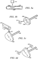
- Figs. 3a - 3d Additional embodiments of detector/flywheel arrangements are shown in Figs. 3a - 3d .
- the detector 144 emits and detects light reflected off the surface of the motor shaft 142.
- the shaft has a dark, non-reflective band 142a (shown in cross hatch) extending 180 degrees around the radial surface of the shaft 142.
- the other 180 degree portion 142b of the shaft has a light, reflective surface.
- the detector 144 is axially aligned with the non-reflective band 142a of the shaft 142.
- the detector 144 and shaft 142 are synchronized so that the detector 144 reads the boundary between the reflective and non-reflective surfaces at the same time the pump 20 transitions from one phase of the pump cycle to the other.
- the detector 244 comprises a Hall effect transducer that interacts with a magnetic encoder on the flywheel.
- the encoder on one half 240a of the flywheel 240 has an opposite polarity than the encoder on the other half 240b of the flywheel.
- the detector 244 and flywheel 240 are synchronized so that the detector 44 detects a change in polarity at the same time the pump 20 transitions from one phase of the pump cycle to the other.
- the detector 344 comprises a microswitch and cam-shaped flywheel 340.
- the microswitch includes a cam follower 347 that tracks the outer, irregularly-shaped periphery of the flywheel 340.
- the detector 344 and flywheel 340 are synchronized so that the microswitch is either opened or closed at the same time the pump 20 transitions from one phase of the pump cycle to the other.
- the detector 444 detects light directly emitted from a source 445.
- the flywheel 440 has an irregular shape that cyclically interrupts the line of sight between the light source 445 and the detector.
- the detector 444 and flywheel 440 are synchronized so that the detector 444 detects an interruption and then resumption of the light source at the same time the pump 20 transitions from one phase of the pump cycle to the other.
- the detector 544 comprises an ultrasonic sensor 544 mounted inside piston chamber 532.
- the ultrasonic sensor 544 emits sound waves towards the diaphragm 534 to continuously measure the distance between the detector 544 and the diaphragm 534.
- a maximum or minimum distance reading between the detector 544 and the diaphragm 534 indicates a transition from one phase of the pump cycle to the other.
- Other types of detectors may be used so long as the detector is capable of continuously determining the phase in which the pump is operating and electronically transmitting a signal to the controller that identifies the phase.
- the electrically-actuated valve 22 is located intermediate the conduit 19 connecting the pump 20 to the outlet port 29.
- the valve 22 comprises a three-way solenoid valve such as shown in Fig. 5 .
- the solenoid valve 22 has a housing 52 with a normally-closed (NC) port 54, a common port 56, and a normally-open (NO) port 58.
- the NC port 54 is connected to the utility port 29 by a section 19b of the conduit 19.
- the common port 56 of the valve is connected to the common port 29 of the pump by a section 19a of the conduit 19.
- the NO port 58 vents to the atmosphere.
- the solenoid valve has a ferrous reciprocating element 60, which has a valve head 61 at one end and a cylindrical base 63 at the other end.
- An induction coil 64 surrounds the base 63 while a compression spring 68 surrounds the head 61.
- First and second seals 70, 72 are seated on opposed ends of the head 61.
- the compression spring 68 normally biases the valve head 61 to a first position wherein the common port 56 is arranged in fluid connection with the NO port 58 and the NC 54 port is closed. In the first position, the internal conduit 19 between the pump 20 and the utility port 29 is closed.
- a magnetic field urges the valve head 61 to a second position wherein the common port 56 is arranged in fluid connection with the NC 54 port 58 and the NO port 58 is closed. In the second position, the internal conduit 19 between the pump 20 and the utility port 29 is open.
- the user interface 26 comprises a first trigger 26, which activates the device in the positive pressure mode, and a second trigger 27, which activates the device in the negative pressure mode.
- the device 10 is inactive until one of the triggers is a depressed.
- other forms of input device such as pressure sensitive transducers, capacitance transducers, multi-directional joy stick, key pad, computer, or other electronic input devices may be connected to the controller 24.
- the valve 22, detector 44, and user interface 26 communicate with the controller 24.
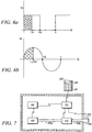
- the detector 44 continuously transmits to the controller 24 a signal identifying the phase of the pump cycle in which the pump is operating.
- the signal has the square wave illustrated in Fig. 6a , which illustrates voltage (v) as a function of the pump cycle.
- the signal has the sinusoidal shape shown in Fig. 6b , which illustrates distance (d) of the diaphragm from a neutral position as a function of the pump cycle.
- the device not only selectively creates negative or positive pressure at the utility port 29, but also controls additional fluid flow properties.
- the triggers 26, 27 may be connected to potentiometers.
- the user controls the volumetric flow rate by controlling the distance each trigger 26, 27 is depressed.
- Other known user interface devices such as described above could be substituted for the triggers 26, 27.
- the device 110 delivers a measured volume (V) of fluid through the utility port 129.
- the volume displacement per unit stroke (DPS) of the pump 120 is programmed into the controller 124.
- the DPS may be calculated based on the dimensions of the pump 120 or experimentally calculated using a calibration scale.
- the controller 124 calculates and allows the pump 120 to operate for the requisite number (N) of strokes to deliver the desired volume (V) of fluid. Data from the detector 118 allows the controller 124 to count each stroke of the pump.
- the user interface 125 may comprise a keypad or a computer.
- the keypad 125 may include a plurality of input keys 127 and an LCD 128, which displays a wide variety of additional control options that have been programmed into the controller.
- the device 110 includes a sensor 178 that measures the external pressure or head at the utility port 129.
- bi-directional pumps may be used for the invention.
- a solenoid-activated diaphragm pump such as manufactured by MEDO U.S.A., Inc.
- Other types of bi-directional pump may be used so long as the detector can continuously determine the phase of the pump cycle in which the pump is operating.
- the aforementioned embodiments have been described with reference to a detector that continuously determines the phase in which the pump is operating by tracking movement of a cyclically-moving element of the pump.
- other types of detectors may be used so long as it is capable of continuously determining the phase in which the pump is operating and electronically transmitting a signal to the controller that identifies the phase.
- the detector may identify the transition from one phase to another by detecting a change in polarity created by the solenoid.
- the device 210 includes a detector 218, bi-directional pump 220, controller 224, and user interface 225 that are similar in construction and arrangement as described above.
- the three-way solenoid valve of the embodiment in Fig. 1 is replaced with a pair of electrically-actuated, two-way valves, 280, 281, each of which regulates fluid flow through one branch of a manifold 283 connected to the common fluid flow port 246 of the pump 220.
- One valve 280 regulates fluid flow from the pump 220 to the utility port 229 via a fluid flow conduit 219.
- the other valve 281 regulates fluid flow from the pump 220 to an atmospheric vent 282.
- the controller 224 uses the input signal from the detector 218, the controller 224 selectively opens and closes the valves 280, 281 in synchronization with the phases of the pump cycle to create either positive or negative pressure at the utility port 229.
- the valves 280, 281 comprise Piezo ceramic element valves, which are known to have the fast response time required to synchronize with the changing phases of the pump 220.
- the device controls uni-directional fluid flow.
- the device 310 includes a uni-directional pump 385, controller 324, user interface 325, and electrically-actuated, three-way valve 322.
- the device 310 may also include a detector 318.
- the valve 322 comprises a solenoid valve such as described above.
- the controller 324 selectively actuates the valve 322 to deliver fluid at preset intervals, controlled quantities, measured volumes (V), defined flow rates, and other properties or steps.
- a pipetting device in accordance with a further embodiment of the present invention is shown in Fig. 10 and is designated generally by reference numeral 410.
- the pipetting device 410 is constructed to admit and emit fluid from a disposable pipette 406, which may vary in size and shape.
- the pipetting device 410 has the shape of a known "gun-type" pipettor, which is easily gripped by the user 408 (shown in phantom).
- the device 410 could be made in a variety of shapes and sizes.
- the housing 411 of the pipetting device 412 has a handle portion 414 and a barrel portion 415 oriented transversely to the handle portion 414.
- a nosepiece or pipette connector 416 is fixed to and oriented downwardly transverse to the barrel portion 415.
- the pipette connector 416 is constructed and arranged to removably attach pipettes 406 of various lengths and diameters.
- the pipette connector 16 may include a hydrophobic filter 417, which may be removed and replaced. The filter 417 prevents contamination of the pipetting device 410 in the event the pipette 18 is overadmitted with fluid.
- the device 412 has a bi-directional pump 420, control valve 422, and controller 424.
- An internal conduit 419 connects the pump 420 to the pipette connector 416.
- the control valve comprises a three-way, electrically-actuated solenoid valve 422 and is located intermediate the internal conduit 419.
- a detector (not shown) is built into the pump 420.
- a positive air flow trigger 426 and negative air flow trigger 428 extend from the handle portion 414 and are connected to the controller 424.
- the controller 424 actuates the valve 422 in response to signals generated by depression of either the positive air flow trigger 426 or negative air flow trigger 428.
- the pipetting device may be provided with a more sophisticated user interface, which would allow the user to control the wide variety of fluid flow properties described above.
Landscapes
- Engineering & Computer Science (AREA)
- Mechanical Engineering (AREA)
- General Engineering & Computer Science (AREA)
- Health & Medical Sciences (AREA)
- Clinical Laboratory Science (AREA)
- Chemical & Material Sciences (AREA)
- Chemical Kinetics & Catalysis (AREA)
- Control Of Positive-Displacement Pumps (AREA)
- Reciprocating Pumps (AREA)
- Jet Pumps And Other Pumps (AREA)
Claims (24)
- Vorrichtung (10, 110, 210, 310) zum Steuern des bidirektionalen Fluidstroms, umfassend:a) eine Versorgungsöffnung (29, 129, 229),b) eine bidirektionale Pumpe (20, 120, 220) mit einer gemeinsamen Fluidströmungsöffnung (46, 246), die in einem kontinuierlichen Pumpzyklus zwischen einer Überdruckphase und einer Unterdruckphase arbeitet, um entweder einen Überdruck oder einen Unterdruck an der gemeinsamen Fluidströmungsöffnung (46, 246) in einer zyklisch wechselnden Richtung zu erzeugen,c) Vorrichtung (19a) zum Verbinden der gemeinsamen Fluidströmungsöffnung (46, 246) und der Versorgungsöffnung (29, 129, 229) in Fluidverbindung,dadurch gekennzeichnet, dass die Vorrichtung ferner umfasst:d) eine Ventileinrichtung (22) zum Regeln des Luftstroms zwischen der gemeinsamen Fluidströmungsöffnung (46, 246), der Versorgungsöffnung (29, 129, 229) und der Atmosphäre, wobei die Ventileinrichtung (22) zwischen einer ersten, die gemeinsame Fluidströmungsöffnung (46, 246) und die Versorgungsöffnung (29, 129 229) trennenden Position arbeitet und die gemeinsame Fluidströmungsöffnung (46, 246) mit der Atmosphäre verbindet, und einer zweiten Position, die die gemeinsame Fluidströmungsöffnung (46, 246) und die Versorgungsöffnung (29, 129, 229) in Fluidverbindung verbindet und die gemeinsame Fluidströmungsöffnung (46, 246) von der Atmosphäre trennt,e) eine Einrichtung (18, 44, 118, 144, 218, 244, 318, 344, 444, 544) zum kontinuierlichen Erfassen, ob die Pumpe (20, 120, 220) in der Druckphase oder in der Vakuumphase des Pumpenzyklus arbeitet, durch Nachverfolgen der Bewegung eines sich zyklisch bewegenden Elements der Pumpe, undf) eine Steuereinrichtung (24, 124, 224, 324), die mit der Erfassungseinrichtung (18, 44, 118, 144, 218, 244, 318, 344, 444, 544) und der Ventileinrichtung (22) verbunden ist, wobei die Steuereinrichtung (24, 124, 224, 324) die Ventileinrichtung (22) zwischen der ersten Position und der zweiten Position in Synchronisation mit der Überdruckphase und der Unterdruckphase kontinuierlich betätigt, um entweder einen kontinuierlichen positiven Fluidstrom durch die Versorgungsöffnung (29, 129, 229) oder einen kontinuierlichen negativen Fluidstrom durch die Versorgungsöffnung (29, 129, 229) zu erzeugen.
- Vorrichtung (10, 110, 210, 310) nach Anspruch 1, wobei die Ventileinrichtung (22) ein elektrisch gesteuertes Ventil (22) umfasst, die kontinuierliche Erfassungseinrichtung (18, 44, 118, 144, 218, 244, 318, 344, 444, 544) einen Detektor (18, 44, 118, 144, 218, 244, 318, 344, 444, 544) umfasst und die Steuereinrichtung (24, 124, 224, 324) eine Steuerung (24, 124, 224, 324) umfasst.
- Vorrichtung (10, 110, 210, 310) nach Anspruch 2, wobei ein negativer Fluidstrom an der Versorgungsöffnung (29, 129, 229) erzeugt wird, indem das Ventil (22) während der Vakuumphase des Pumpenzyklus zyklisch in die zweite Position betätigt wird und dann das Ventil (22) während der Druckphase des Pumpenzyklus zurück in die erste Position betätigt wird und ein positiver Fluidstrom an der Versorgungsöffnung (29, 129, 229) erzeugt wird, indem das Ventil (22) während der Druckphase des Pumpenzyklus zyklisch in die zweite Position und dann das Ventil (22) während der Vakuumphase des Pumpenzyklus zurück in die erste Position betätigt wird.
- Vorrichtung (10, 110, 210, 310) nach Anspruch 3, umfassend eine Einrichtung zum Steuern einer Fließgeschwindigkeit (22, 26, 27) durch die Versorgungsöffnung (29, 129, 229).
- Vorrichtung (10, 110, 210, 310) nach Anspruch 4, wobei die Einrichtung zum Steuern der Fließgeschwindigkeit (22, 26, 27) durch die Versorgungsöffnung die Zeitspanne ändert, in der das Ventil (22) während einer beliebigen der beiden Phasen des Pumpenzyklus in die zweite Position betätigt wird.
- Vorrichtung (10, 110, 210, 310) nach Anspruch 2, wobei die Pumpe (2) ein hin- und hergehendes Volumenverdrängungselement (34, 60, 534) enthält, das während der einen Hälfte des Pumpenzyklus einen Luftüberdruck und während der anderen Hälfte des Pumpenzyklus einen Luftunterdruck erzeugt.
- Vorrichtung (10, 110, 210, 310) nach Anspruch 6, wobei der Detektor (18, 44, 144, 244, 344, 444, 544) einen Fotosensor umfasst, der eine Bewegung des Volumenverdrängungselements (34, 60, 534) erfasst.
- Vorrichtung (10, 110, 210, 310) nach Anspruch 6, wobei der Detektor (18, 44, 144, 244, 344, 444, 544) einen Ultraschallsensor (544) umfasst, der eine Bewegung des Volumenverdrängungselements (34, 60, 534) erfasst.
- Vorrichtung (10, 110, 210, 310) nach Anspruch 2, welche eine Einrichtung zum Steuern des Durchflusses eines gemessenen Flüssigkeitsvolumens (V) durch die Versorgungsöffnung (29, 129, 229) einschließt.
- Vorrichtung (10, 110, 210, 310) nach Anspruch 2, wobei die volumetrische Steuereinrichtung (24, 124, 224, 324) die Pumpe (20, 120, 220) für eine berechnete Anzahl (N) von Pumpenzyklen auf der Grundlage der Volumenverdrängung pro Hub (displacement per stroke, DPS) der Pumpe (20, 120, 220) berechnet und betreibt.
- Vorrichtung (10, 110, 210, 310) nach Anspruch 2, wobei das Ventil (22) ein Dreiwege-Magnetventil (22) mit einem gemeinsamen Anschluss (56), der mit der Pumpe (20, 120, 220) verbunden ist, einen normalerweise offenen (NO-) Anschluss (58), der zur Atmosphäre entlüftet wird, und einen normalerweise geschlossenen (NC-) Anschluss (54), der mit der Versorgungsöffnung (29, 129, 229) verbunden ist, umfasst.
- Vorrichtung (10, 110, 210, 310) nach Anspruch 11, wobei das Ventil (22) den normalerweise geschlossenen (NC-) Anschluss (54) und den gemeinsamen Anschluss (56) in Fluidverbindung in der zweiten Position verbindet und den normalerweise offenen (NO-) Anschluss (58) und den gemeinsamen Anschluss (56) in Fluidverbindung in der ersten Position verbindet.
- Vorrichtung (10, 110, 210, 310) nach Anspruch 2, wobei das Ventil (22) ein erstes, elektrisch betätigtes Zweiwegeventil (280), das den Fluidstrom durch eine Leitung steuert, und ein zweites, elektrisch betätigtes Zweiwegeventil (281) umfasst, das den Fluidstrom von der Pumpe (20, 120, 220) zur Atmosphäre steuert.
- Vorrichtung (10, 110, 210, 310) nach Anspruch 2, die eine mit der Steuerung (24, 124, 224, 324) verbundene Benutzerschnittstelle (25, 125, 225, 325) einschließt.
- Vorrichtung (10, 110, 210, 310) nach Anspruch 10, einschließlich eines Sensors (78, 178), der den Kopfdruck an der Versorgungsöffnung (29, 129, 229) misst und den Kopfdruck an die Steuerung (24, 124, 224, 324) übermittelt.
- Vorrichtung (10, 110, 210, 310) nach Anspruch 15, wobei die volumetrische Steuereinrichtung (24, 124, 224, 324) den Kopfdruck verwendet, um die Anzahl (N) der für die vorbestimmte volumetrische Förderung erforderlichen Pumpenzyklen zu berechnen.
- Vorrichtung (10, 110, 210, 310) nach Anspruch 2, wobei die Erfassungseinrichtung (18, 44, 118, 144, 218, 244, 318, 344, 444, 544) die Bewegung eines sich zyklisch bewegenden Elements (40, 142, 240, 340, 440, 534) der Pumpe (20, 120, 220) erfasst.
- Verfahren zum Steuern eines positiven und negativen Fluidstroms durch eine Versorgungsöffnung (29, 129, 229), umfassend die Schritte:a) Bereitstellen einer bidirektionalen Pumpe (20, 120, 220) mit einer gemeinsamen Fluidströmungsöffnung (46, 246), die in einem kontinuierlichen Pumpzyklus zwischen einer Überdruckphase und einer Unterdruckphase arbeitet, um an der gemeinsamen Fluidströmungsöffnung (46, 246) entweder einen Überdruck oder einen Unterdruck in einer zyklisch wechselnden Richtung zu erzeugen,b) kontinuierliches Erfassen, ob die bidirektionale Pumpe (20, 120, 220) in der Druck- oder Vakuumphase arbeitet, durch Nachverfolgen einer Bewegung eines sich zyklisch bewegenden Elements der bidirektionalen Pumpe (20, 120, 220),c) Erzeugen eines kontinuierlichen positiven Fluidstroms durch die Versorgungsöffnung (29, 129, 229) durch Verbinden des gemeinsamen Fluidströmungsöffnung (46, 246) in Fluidverbindung mit der Versorgungsöffnung (29, 129, 229) während der Druckphase und Trennen des gemeinsamen Fluidstroms (46, 246) von der Versorgungsöffnung (29, 129, 229) während der Vakuumphase in Synchronisation mit der Überdruckphase und der Unterdruckphase an der gemeinsamen Fluidströmungsöffnung (46, 246),d) Erzeugen eines kontinuierlichen negativen Fluidstroms durch die Versorgungsöffnung (29, 129, 229) durch Verbinden der gemeinsamen Fluidströmungsöffnung (46, 246) in Fluidverbindung mit der Versorgungsöffnung (29, 129, 229) während der Vakuumphase, und Trennen der gemeinsamen Fluidströmungsöffnung (46, 246) von der Versorgungsöffnung und der Atmosphäre (29, 129, 229) während der Druckphase synchron mit der Überdruckphase und der Unterdruckphase der gemeinsamen Fluidströmungsöffnung (46, 246).
- Verfahren nach Anspruch 18, das den Schritt des Steuerns einer Fließgeschwindigkeit durch die Versorgungsöffnung (29, 129, 229) einschließt.
- Verfahren nach Anspruch 19, das den Schritt des Abgebens gemessener Fluidmengen durch die Versorgungsöffnung (29, 129, 229) einschließt.
- Pipettiervorrichtung (410) zum Aufnehmen und Abgeben von Fluid aus einer Wegwerfvorrichtung (406) mit einer Vorrichtung (10, 110, 201, 310) zum Steuern eines bidirektionalen Fluidstroms gemäß Anspruch 1, wobei die Pipettiervorrichtung (410) ein Gehäuse (411) mit einem Handgriffabschnitt (414), einen Pipettenverbinder (416) in der Nähe der Versorgungsöffnung (29, 129, 229) und eine Benutzerschnittstelle (426, 428) aufweist.
- Pipettiervorrichtung (410) nach Anspruch 21 mit einem Sensor, der den Kopfdruck an dem Pipettenanschluss (416) misst.
- Pipettiervorrichtung (410) nach Anspruch 22, wobei die Pumpe eine Membranpumpe (420) mit einem Motor mit einer Welle (38) und einem mit der Welle (38) verbundenen hin- und hergehenden Volumenverdrängungselement (34, 534) umfasst, wobei das Element (34, 534) während einer Hälfte des Pumpzyklus einen Überdruck erzeugt und während einer anderen Hälfte des Pumpzyklus einen Unterdruck erzeugt, wobei die Hin- und Herbewegung des Elements (34, 534) durch einen vollständigen Pumpzyklus mit einer einzelnen Drehung der Welle (38) synchronisiert ist.
- Vorrichtung (10, 110, 210, 310) nach Anspruch 1, wobei die Ventileinrichtung (22) ein einzelnes Dreiwegeventil ist, das einen einzigen reziproken Ventilkopf (61) aufweist, der zwischen der ersten und der zweiten Position bewegbar ist.
Applications Claiming Priority (2)
| Application Number | Priority Date | Filing Date | Title |
|---|---|---|---|
| US11/413,143 US20070253832A1 (en) | 2006-04-27 | 2006-04-27 | Method and apparatus for controlling fluid flow |
| PCT/US2007/010277 WO2007127389A2 (en) | 2006-04-27 | 2007-04-27 | Method and apparatus for controlling fluid flow |
Publications (3)
| Publication Number | Publication Date |
|---|---|
| EP2016286A2 EP2016286A2 (de) | 2009-01-21 |
| EP2016286A4 EP2016286A4 (de) | 2012-07-18 |
| EP2016286B1 true EP2016286B1 (de) | 2018-09-05 |
Family
ID=38648488
Family Applications (1)
| Application Number | Title | Priority Date | Filing Date |
|---|---|---|---|
| EP07794396.7A Active EP2016286B1 (de) | 2006-04-27 | 2007-04-27 | Verfahren und vorrichtung zur steuerung eines flüssigkeitsflusses |
Country Status (5)
| Country | Link |
|---|---|
| US (1) | US20070253832A1 (de) |
| EP (1) | EP2016286B1 (de) |
| JP (1) | JP5185256B2 (de) |
| CN (1) | CN101443551B (de) |
| WO (1) | WO2007127389A2 (de) |
Cited By (2)
| Publication number | Priority date | Publication date | Assignee | Title |
|---|---|---|---|---|
| WO2025122781A1 (en) * | 2023-12-07 | 2025-06-12 | Ortho-Clinical Diagnostics, Inc. | Flowrate controlled fluidics systems and immunoassay methods using the same |
| EP4703039A1 (de) * | 2024-09-02 | 2026-03-04 | Integra Biosciences AG | Pipettierhilfe mit stufenloser bedienung |
Families Citing this family (11)
| Publication number | Priority date | Publication date | Assignee | Title |
|---|---|---|---|---|
| US9158308B2 (en) * | 2011-05-13 | 2015-10-13 | Fluke Corporation | Apparatus using electronically-controlled valves |
| CN103688053B (zh) * | 2011-07-28 | 2016-10-05 | 艺康股份有限公司 | 用于计量流体的隔膜泵和相应方法 |
| JP6744305B2 (ja) * | 2014-12-01 | 2020-08-19 | エコラボ ユーエスエー インコーポレイティド | 流体を投与するためのダイアフラムポンプ、及びそれに応じた方法 |
| US11624362B2 (en) * | 2015-08-07 | 2023-04-11 | Magpumps Limited | Device for pumping fluid |
| GB2541031B (en) * | 2015-08-07 | 2017-09-06 | Magpumps Ltd | Gear pump for pumping fluid |
| US11911767B2 (en) | 2019-10-25 | 2024-02-27 | Mettler-Toledo Rainin, LLC | Positive displacement pipette syringe identification system |
| US11369954B2 (en) * | 2019-10-25 | 2022-06-28 | Mettler-Toledo Rainin, LLC | Powered positive displacement pipette assembly |
| US11471878B2 (en) * | 2019-10-25 | 2022-10-18 | Mettler-Toledo Rainin, LLC | Powered positive displacement pipette |
| KR102794545B1 (ko) * | 2020-06-12 | 2025-04-09 | 주식회사 톱텍 | 고속 대용량 피펫 장치 |
| CN113663541A (zh) * | 2021-06-04 | 2021-11-19 | 深圳市和来生物技术有限公司 | 应用于微流控芯片的液体混匀装置以及微流控芯片 |
| US12472491B2 (en) | 2022-06-28 | 2025-11-18 | Mettler-Toledo Rainin, LLC | Positive displacement pipette syringe with reduced fluid drag |
Family Cites Families (29)
| Publication number | Priority date | Publication date | Assignee | Title |
|---|---|---|---|---|
| US3039491A (en) * | 1959-07-15 | 1962-06-19 | Ranco Inc | Valve mechanism for fluid systems |
| US3835874A (en) * | 1967-12-22 | 1974-09-17 | F Dellasala | Method of introducing liquid doses |
| DE2442372A1 (de) * | 1974-09-04 | 1976-03-18 | Bosch Gmbh Robert | Elektromagnetische 3-wege-ventilanordnung |
| US4055281A (en) * | 1976-06-11 | 1977-10-25 | National Instrument Company | Filling unit with air-operated spool valve system |
| US4475666A (en) * | 1981-08-31 | 1984-10-09 | American Hospital Supply Corporation | Automated liquid dispenser control |
| JPS60128978A (ja) * | 1983-12-16 | 1985-07-10 | Nippon Zeon Co Ltd | 気体駆動型ポンプの駆動装置 |
| US4780064A (en) * | 1986-02-10 | 1988-10-25 | Flow Industries, Inc. | Pump assembly and its method of operation |
| US4754690A (en) * | 1986-09-19 | 1988-07-05 | Allied-Signal Inc. | Electrically controlled hydraulically driven actuator assembly |
| JP2925803B2 (ja) * | 1991-09-11 | 1999-07-28 | 東洋エンジニアリング株式会社 | オイルフリー真空ポンプ |
| US5263513A (en) * | 1992-09-22 | 1993-11-23 | Roe Steven N | Dual flow passage poppet valve |
| DE4324533C2 (de) * | 1993-07-21 | 1996-04-25 | Lucas Ind Plc | Ventilanordnung |
| US5509318A (en) * | 1993-10-13 | 1996-04-23 | Manostat Corporation | Memory Mopet |
| US5437218A (en) * | 1994-04-04 | 1995-08-01 | Pcm Pompes | Diaphragm pump having variable displacement |
| US5520532A (en) * | 1994-08-01 | 1996-05-28 | United Technologies Corporation | Molding assembly for forming airfoil structures |
| US5540215A (en) * | 1995-05-08 | 1996-07-30 | Gas Research Institute | Method and apparatus for heating a liquid |
| US6012644A (en) * | 1997-04-15 | 2000-01-11 | Sturman Industries, Inc. | Fuel injector and method using two, two-way valve control valves |
| US6199533B1 (en) * | 1999-02-01 | 2001-03-13 | Cummins Engine Company, Inc. | Pilot valve controlled three-way fuel injection control valve assembly |
| JP3863292B2 (ja) * | 1998-05-29 | 2006-12-27 | シーケーディ株式会社 | 液体供給装置 |
| JP2001065514A (ja) * | 1999-08-31 | 2001-03-16 | Sumitomo Electric Ind Ltd | 比例圧力制御弁 |
| JP2001193896A (ja) * | 2000-01-12 | 2001-07-17 | Mikuni Adec Corp | 潤滑油供給装置 |
| DE10052819B4 (de) | 2000-10-24 | 2004-02-19 | Fraunhofer-Gesellschaft zur Förderung der angewandten Forschung e.V. | Pipettensystem und Pipettenarray sowie Verfahren zum Befüllen eines Pipettensystems |
| EP1296061A3 (de) * | 2001-09-21 | 2005-03-16 | Hitachi, Ltd. | Hochdruckkraftstoffpumpe |
| JP3599726B2 (ja) * | 2002-08-30 | 2004-12-08 | 康克 井野内 | 微量液体吸入吐出装置 |
| JP2004169677A (ja) * | 2002-11-20 | 2004-06-17 | Myotoku Ltd | 正圧負圧供給装置 |
| DE10344700A1 (de) * | 2003-09-26 | 2005-04-14 | Hirschmann Laborgeräte GmbH & Co. KG | Mehrkanal-Pipettiervorrichtung |
| US20050079079A1 (en) * | 2003-10-09 | 2005-04-14 | Wahlin Sigvard J. | Dilution system |
| US7396512B2 (en) * | 2003-11-04 | 2008-07-08 | Drummond Scientific Company | Automatic precision non-contact open-loop fluid dispensing |
| US7381371B2 (en) * | 2004-01-16 | 2008-06-03 | Heathrow Scientific Llc | Pipette device with pivotable nozzle assembly |
| JP2005256751A (ja) * | 2004-03-12 | 2005-09-22 | Matsushita Electric Ind Co Ltd | 流体噴出装置 |
-
2006
- 2006-04-27 US US11/413,143 patent/US20070253832A1/en not_active Abandoned
-
2007
- 2007-04-27 WO PCT/US2007/010277 patent/WO2007127389A2/en not_active Ceased
- 2007-04-27 CN CN2007800152939A patent/CN101443551B/zh active Active
- 2007-04-27 EP EP07794396.7A patent/EP2016286B1/de active Active
- 2007-04-27 JP JP2009507827A patent/JP5185256B2/ja active Active
Non-Patent Citations (1)
| Title |
|---|
| None * |
Cited By (3)
| Publication number | Priority date | Publication date | Assignee | Title |
|---|---|---|---|---|
| WO2025122781A1 (en) * | 2023-12-07 | 2025-06-12 | Ortho-Clinical Diagnostics, Inc. | Flowrate controlled fluidics systems and immunoassay methods using the same |
| EP4703039A1 (de) * | 2024-09-02 | 2026-03-04 | Integra Biosciences AG | Pipettierhilfe mit stufenloser bedienung |
| CH722090A1 (de) * | 2024-09-02 | 2026-03-13 | Integra Biosciences Ag | Pipettierhilfe mit stufenloser Bedienung |
Also Published As
| Publication number | Publication date |
|---|---|
| EP2016286A2 (de) | 2009-01-21 |
| CN101443551B (zh) | 2013-03-27 |
| JP2009535557A (ja) | 2009-10-01 |
| WO2007127389A3 (en) | 2008-07-31 |
| EP2016286A4 (de) | 2012-07-18 |
| WO2007127389A2 (en) | 2007-11-08 |
| CN101443551A (zh) | 2009-05-27 |
| US20070253832A1 (en) | 2007-11-01 |
| JP5185256B2 (ja) | 2013-04-17 |
Similar Documents
| Publication | Publication Date | Title |
|---|---|---|
| EP2016286B1 (de) | Verfahren und vorrichtung zur steuerung eines flüssigkeitsflusses | |
| TWI580866B (zh) | 隔膜真空泵 | |
| US8231842B2 (en) | Positive displacement pump with pressure sensor | |
| EP2561932B1 (de) | Modulare Spritzvorrichtungen | |
| EP1531004A2 (de) | Flüssigkeitsdispenser mit automatischer kontakfreier Regelsteuerung mit offenem Regelkreis | |
| CN110088472B (zh) | 医用液体的容积泵和血液治疗设备及其控制的方法 | |
| JP7089792B2 (ja) | 液体の精密な分割量を分注する方法および装置 | |
| CA2604358A1 (en) | Fluid delivery device with autocalibration | |
| JP6169862B2 (ja) | ピペッティング装置およびその製造方法 | |
| CN111287925B (zh) | 一种计量泵及计量系统 | |
| JP2782679B2 (ja) | レジスト処理装置 | |
| US11229905B2 (en) | Method and apparatus for dispensing precise aliquots of liquid | |
| EP3751241A1 (de) | Fluiddosiersystem | |
| US20260061415A1 (en) | Pipetting aid with stepless operation | |
| JP7469752B2 (ja) | 計量ポンプ | |
| CN121772979A (zh) | 移液装置、移液机器人和用于使用移液装置的方法 | |
| CN114206501A (zh) | 用于置换流体体积的置换设备和方法 | |
| Kouzani et al. | Design and construction of a micropump for drug delivery applications | |
| WO2013156408A1 (en) | Pipetting arrangement and method of controlling pipetting |
Legal Events
| Date | Code | Title | Description |
|---|---|---|---|
| PUAI | Public reference made under article 153(3) epc to a published international application that has entered the european phase |
Free format text: ORIGINAL CODE: 0009012 |
|
| AK | Designated contracting states |
Kind code of ref document: A2 Designated state(s): AT BE BG CH CY CZ DE DK EE ES FI FR GB GR HU IE IS IT LI LT LU LV MC MT NL PL PT RO SE SI SK TR |
|
| AX | Request for extension of the european patent |
Extension state: AL BA HR MK RS |
|
| 17P | Request for examination filed |
Effective date: 20090114 |
|
| RBV | Designated contracting states (corrected) |
Designated state(s): DE FR GB |
|
| RIC1 | Information provided on ipc code assigned before grant |
Ipc: F04B 17/00 20060101AFI20090216BHEP |
|
| DAX | Request for extension of the european patent (deleted) | ||
| RBV | Designated contracting states (corrected) |
Designated state(s): DE FR GB |
|
| REG | Reference to a national code |
Ref country code: DE Ref legal event code: R079 Ref document number: 602007056041 Country of ref document: DE Free format text: PREVIOUS MAIN CLASS: F04B0049060000 Ipc: F04B0017000000 |
|
| A4 | Supplementary search report drawn up and despatched |
Effective date: 20120619 |
|
| RIC1 | Information provided on ipc code assigned before grant |
Ipc: F04B 17/00 20060101AFI20120613BHEP Ipc: F04B 45/047 20060101ALI20120613BHEP Ipc: F04B 45/04 20060101ALI20120613BHEP Ipc: B01L 3/02 20060101ALI20120613BHEP Ipc: F04B 43/00 20060101ALI20120613BHEP Ipc: F04B 53/16 20060101ALI20120613BHEP |
|
| 17Q | First examination report despatched |
Effective date: 20150527 |
|
| STAA | Information on the status of an ep patent application or granted ep patent |
Free format text: STATUS: EXAMINATION IS IN PROGRESS |
|
| GRAP | Despatch of communication of intention to grant a patent |
Free format text: ORIGINAL CODE: EPIDOSNIGR1 |
|
| STAA | Information on the status of an ep patent application or granted ep patent |
Free format text: STATUS: GRANT OF PATENT IS INTENDED |
|
| INTG | Intention to grant announced |
Effective date: 20180426 |
|
| GRAS | Grant fee paid |
Free format text: ORIGINAL CODE: EPIDOSNIGR3 |
|
| GRAA | (expected) grant |
Free format text: ORIGINAL CODE: 0009210 |
|
| STAA | Information on the status of an ep patent application or granted ep patent |
Free format text: STATUS: THE PATENT HAS BEEN GRANTED |
|
| AK | Designated contracting states |
Kind code of ref document: B1 Designated state(s): DE FR GB |
|
| REG | Reference to a national code |
Ref country code: GB Ref legal event code: FG4D |
|
| REG | Reference to a national code |
Ref country code: DE Ref legal event code: R096 Ref document number: 602007056041 Country of ref document: DE |
|
| REG | Reference to a national code |
Ref country code: DE Ref legal event code: R097 Ref document number: 602007056041 Country of ref document: DE |
|
| PLBE | No opposition filed within time limit |
Free format text: ORIGINAL CODE: 0009261 |
|
| STAA | Information on the status of an ep patent application or granted ep patent |
Free format text: STATUS: NO OPPOSITION FILED WITHIN TIME LIMIT |
|
| 26N | No opposition filed |
Effective date: 20190606 |
|
| PGFP | Annual fee paid to national office [announced via postgrant information from national office to epo] |
Ref country code: DE Payment date: 20250625 Year of fee payment: 19 |
|
| PGFP | Annual fee paid to national office [announced via postgrant information from national office to epo] |
Ref country code: GB Payment date: 20250418 Year of fee payment: 19 |
|
| PGFP | Annual fee paid to national office [announced via postgrant information from national office to epo] |
Ref country code: FR Payment date: 20250424 Year of fee payment: 19 |