EP2016284B1 - Vorrichtung zur erzeugung von elektrischen energie sowie verfahren zur steuerung dieser vorrichtung - Google Patents
Vorrichtung zur erzeugung von elektrischen energie sowie verfahren zur steuerung dieser vorrichtung Download PDFInfo
- Publication number
- EP2016284B1 EP2016284B1 EP06756283A EP06756283A EP2016284B1 EP 2016284 B1 EP2016284 B1 EP 2016284B1 EP 06756283 A EP06756283 A EP 06756283A EP 06756283 A EP06756283 A EP 06756283A EP 2016284 B1 EP2016284 B1 EP 2016284B1
- Authority
- EP
- European Patent Office
- Prior art keywords
- wing airfoil
- information
- pieces
- flight
- airfoil
- Prior art date
- Legal status (The legal status is an assumption and is not a legal conclusion. Google has not performed a legal analysis and makes no representation as to the accuracy of the status listed.)
- Active
Links
Images

Classifications
-
- F—MECHANICAL ENGINEERING; LIGHTING; HEATING; WEAPONS; BLASTING
- F03—MACHINES OR ENGINES FOR LIQUIDS; WIND, SPRING, OR WEIGHT MOTORS; PRODUCING MECHANICAL POWER OR A REACTIVE PROPULSIVE THRUST, NOT OTHERWISE PROVIDED FOR
- F03D—WIND MOTORS
- F03D7/00—Controlling wind motors
- F03D7/06—Controlling wind motors the wind motors having rotation axis substantially perpendicular to the air flow entering the rotor
-
- F—MECHANICAL ENGINEERING; LIGHTING; HEATING; WEAPONS; BLASTING
- F03—MACHINES OR ENGINES FOR LIQUIDS; WIND, SPRING, OR WEIGHT MOTORS; PRODUCING MECHANICAL POWER OR A REACTIVE PROPULSIVE THRUST, NOT OTHERWISE PROVIDED FOR
- F03D—WIND MOTORS
- F03D3/00—Wind motors with rotation axis substantially perpendicular to the air flow entering the rotor
- F03D3/005—Wind motors with rotation axis substantially perpendicular to the air flow entering the rotor the axis being vertical
-
- F—MECHANICAL ENGINEERING; LIGHTING; HEATING; WEAPONS; BLASTING
- F03—MACHINES OR ENGINES FOR LIQUIDS; WIND, SPRING, OR WEIGHT MOTORS; PRODUCING MECHANICAL POWER OR A REACTIVE PROPULSIVE THRUST, NOT OTHERWISE PROVIDED FOR
- F03D—WIND MOTORS
- F03D5/00—Other wind motors
-
- F—MECHANICAL ENGINEERING; LIGHTING; HEATING; WEAPONS; BLASTING
- F03—MACHINES OR ENGINES FOR LIQUIDS; WIND, SPRING, OR WEIGHT MOTORS; PRODUCING MECHANICAL POWER OR A REACTIVE PROPULSIVE THRUST, NOT OTHERWISE PROVIDED FOR
- F03D—WIND MOTORS
- F03D5/00—Other wind motors
- F03D5/005—Wind motors having a single vane which axis generate a conus or like surface
-
- F—MECHANICAL ENGINEERING; LIGHTING; HEATING; WEAPONS; BLASTING
- F03—MACHINES OR ENGINES FOR LIQUIDS; WIND, SPRING, OR WEIGHT MOTORS; PRODUCING MECHANICAL POWER OR A REACTIVE PROPULSIVE THRUST, NOT OTHERWISE PROVIDED FOR
- F03D—WIND MOTORS
- F03D7/00—Controlling wind motors
-
- G—PHYSICS
- G05—CONTROLLING; REGULATING
- G05D—SYSTEMS FOR CONTROLLING OR REGULATING NON-ELECTRIC VARIABLES
- G05D1/00—Control of position, course, altitude or attitude of land, water, air or space vehicles, e.g. using automatic pilots
- G05D1/08—Control of attitude, i.e. control of roll, pitch, or yaw
- G05D1/0808—Control of attitude, i.e. control of roll, pitch, or yaw specially adapted for aircraft
- G05D1/0866—Control of attitude, i.e. control of roll, pitch, or yaw specially adapted for aircraft specially adapted to captive aircraft
-
- F—MECHANICAL ENGINEERING; LIGHTING; HEATING; WEAPONS; BLASTING
- F05—INDEXING SCHEMES RELATING TO ENGINES OR PUMPS IN VARIOUS SUBCLASSES OF CLASSES F01-F04
- F05B—INDEXING SCHEME RELATING TO WIND, SPRING, WEIGHT, INERTIA OR LIKE MOTORS, TO MACHINES OR ENGINES FOR LIQUIDS COVERED BY SUBCLASSES F03B, F03D AND F03G
- F05B2240/00—Components
- F05B2240/90—Mounting on supporting structures or systems
- F05B2240/91—Mounting on supporting structures or systems on a stationary structure
- F05B2240/917—Mounting on supporting structures or systems on a stationary structure attached to cables
-
- F—MECHANICAL ENGINEERING; LIGHTING; HEATING; WEAPONS; BLASTING
- F05—INDEXING SCHEMES RELATING TO ENGINES OR PUMPS IN VARIOUS SUBCLASSES OF CLASSES F01-F04
- F05B—INDEXING SCHEME RELATING TO WIND, SPRING, WEIGHT, INERTIA OR LIKE MOTORS, TO MACHINES OR ENGINES FOR LIQUIDS COVERED BY SUBCLASSES F03B, F03D AND F03G
- F05B2240/00—Components
- F05B2240/90—Mounting on supporting structures or systems
- F05B2240/92—Mounting on supporting structures or systems on an airbourne structure
- F05B2240/921—Mounting on supporting structures or systems on an airbourne structure kept aloft due to aerodynamic effects
-
- F—MECHANICAL ENGINEERING; LIGHTING; HEATING; WEAPONS; BLASTING
- F05—INDEXING SCHEMES RELATING TO ENGINES OR PUMPS IN VARIOUS SUBCLASSES OF CLASSES F01-F04
- F05B—INDEXING SCHEME RELATING TO WIND, SPRING, WEIGHT, INERTIA OR LIKE MOTORS, TO MACHINES OR ENGINES FOR LIQUIDS COVERED BY SUBCLASSES F03B, F03D AND F03G
- F05B2270/00—Control
- F05B2270/40—Type of control system
- F05B2270/404—Type of control system active, predictive, or anticipative
-
- F—MECHANICAL ENGINEERING; LIGHTING; HEATING; WEAPONS; BLASTING
- F05—INDEXING SCHEMES RELATING TO ENGINES OR PUMPS IN VARIOUS SUBCLASSES OF CLASSES F01-F04
- F05B—INDEXING SCHEME RELATING TO WIND, SPRING, WEIGHT, INERTIA OR LIKE MOTORS, TO MACHINES OR ENGINES FOR LIQUIDS COVERED BY SUBCLASSES F03B, F03D AND F03G
- F05B2270/00—Control
- F05B2270/80—Devices generating input signals, e.g. transducers, sensors, cameras or strain gauges
- F05B2270/807—Accelerometers
-
- Y—GENERAL TAGGING OF NEW TECHNOLOGICAL DEVELOPMENTS; GENERAL TAGGING OF CROSS-SECTIONAL TECHNOLOGIES SPANNING OVER SEVERAL SECTIONS OF THE IPC; TECHNICAL SUBJECTS COVERED BY FORMER USPC CROSS-REFERENCE ART COLLECTIONS [XRACs] AND DIGESTS
- Y02—TECHNOLOGIES OR APPLICATIONS FOR MITIGATION OR ADAPTATION AGAINST CLIMATE CHANGE
- Y02E—REDUCTION OF GREENHOUSE GAS [GHG] EMISSIONS, RELATED TO ENERGY GENERATION, TRANSMISSION OR DISTRIBUTION
- Y02E10/00—Energy generation through renewable energy sources
- Y02E10/70—Wind energy
- Y02E10/728—Onshore wind turbines
-
- Y—GENERAL TAGGING OF NEW TECHNOLOGICAL DEVELOPMENTS; GENERAL TAGGING OF CROSS-SECTIONAL TECHNOLOGIES SPANNING OVER SEVERAL SECTIONS OF THE IPC; TECHNICAL SUBJECTS COVERED BY FORMER USPC CROSS-REFERENCE ART COLLECTIONS [XRACs] AND DIGESTS
- Y02—TECHNOLOGIES OR APPLICATIONS FOR MITIGATION OR ADAPTATION AGAINST CLIMATE CHANGE
- Y02E—REDUCTION OF GREENHOUSE GAS [GHG] EMISSIONS, RELATED TO ENERGY GENERATION, TRANSMISSION OR DISTRIBUTION
- Y02E10/00—Energy generation through renewable energy sources
- Y02E10/70—Wind energy
- Y02E10/74—Wind turbines with rotation axis perpendicular to the wind direction
Definitions
- the present invention refers to a system and a process for automatically controlling the flight of power wing airfoils, particularly for optimising the production of electric energy through the flight of power wing airfoils connected to a system of the "carousel" type.
- object of the present invention is solving the above prior art problems, by providing a system and a process for automatically controlling the flight of power wing airfoils in a predictive way according to a "preferred control strategy" based on observation and prevision of future flight conditions of the wing airfoils, taking into account critical situations and errors due to prediction, allowing to avoid local maxima, oscillations and driving instabilities.
- Another object of the present invention is providing a system and a process for automatically controlling the flight of the power wing airfoils used in the system of the "carousel" type described in Italian Patent Application n. TO2003A000945 and in European Patent Application n. EP 04028646.0 .
- system 1 for automatically controlling the flight of at least one power wing airfoil 2 of the device according to the present invention comprises:
- the device according to the present invention could comprise an instability dissipation drive realised according to the robust control theory.
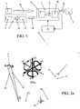
- first pieces of information 3a are directly collected by the first detecting means 3, which other pieces of information can be indirectly obtained from the first pieces of information 3a and consequently which types of first detecting means 3 can be used in the system 1 according to the present invention, it can be useful to briefly examine the geometric piece of information which characterises the position of the wing airfoil 2 in space. With reference therefore to FIG.
- each wing airfoil 2 which goes out of an arm 20a of a system 20 of the "carousel" type of Applications TO2003A000945 and EP 04028646.0 describes, through the two driving cables 21 constraining it to the ground and the imaginary line L which joins its ends, a triangle OAB laying on a plane in space.
- the aerodynamics study introduces the concepts of roll, pitch and yaw, in general of the aircraft attitude.
- a wing airfoil 2 there is a constraint represented by the output nozzle of the driving cables 21 from the arm 20a which compels to renounce to the classical terminology (yaw, roll, pitch).
- the triangle OAB lays on a plane whose position with respect to the ground reference system changes in time depending on the wing airfoil 2 flight.
- orientation of the wing airfoil 2 therefore defines the angle ⁇ described by the plane on which the triangle and the horizontal plane Xy ref lay, apart from the angles ⁇ and ⁇ .
- an artificial ground optical view system can be adopted, this could be constantly impaired by the possible transit of clouds or the lack of a limpid atmosphere, these problems being still more felt if the system 1 is used together with the system 20 of the "carousel" type characterised by high operating flight heights of the wing airfoil 2.
- the first detecting means 3 comprise three-axes accelerometers of the MEMS type in combination with at least one electronic compass.
- the wing airfoil 2 is equipped with at least one magnetometer and at least two three-axes accelerometers placed at the ends of the wing airfoil, preferably next to where the driving cables join the walls of the wing airfoil. Accelerometers on board the wing airfoil therefore solve the functions of:
- Magnetometers complete the provision of pieces of information with the only one which is necessarily not within reach of the system of accelerometers, namely the wing airfoil 2 rotation around the gravity axis.
- Accelerometers of the type used in the system 1 are sensitive to a wide spectrum of accelerations which range from static acceleration, such as gravity acceleration, to phenomena with frequency characteristics of a few kHz.
- the three-axes accelerometer obviously defines a reference Cartesian system XYZ A of its own, like the one shown in FIG. 2b .
- the sensitivity to gravity (static) acceleration allows de facto to distinguish an acceleration variation due to the only slanting of the accelerometer (which implies a variation of direction Z A with respect to Z ref ) from a variation due to the actual displacement of the reference system XYZ A origin, defined as aerodynamic acceleration and which represents the flight of the power wing airfoil.
- the three-axes accelerometer will have a casual position in space.
- the vector g which describes the gravity acceleration, with a constant modulo, direction and sense, can therefore be decomposed into its three components along the versors parallel to the three axes X A , Y A , Z A .
- the gravity vector g position in the coordinates system XYZ A can also be expressed in spherical coordinates, depending on the angles ⁇ and ⁇ and the modulo of g (9.8 m/s 2 ), through the following change of coordinates:
- ⁇ atan 2
- X g A Y g A ⁇ asin X g A where atan 2 is the arc tangent(x) function with the ambiguity resolution (+/-) ⁇ /2.
- the first detecting means 3 can therefore be adapted to implement, in their own intelligence aboard the wing airfoil, suitable algorithms whose purpose is distinguishing gravity acceleration from aerodynamic acceleration, communicating on one hand the spherical coordinates which point out the gravity vector decomposition with respect to the accelerometer coordinates system (and therefore the accelerometer slanting with respect to the fixed reference system), and on the other hand, the real-time evaluation of the aerodynamic acceleration.
- the measure of such acceleration allows, first of all, to implement real-time control techniques which are mandatory for promptly driving the flight of the wing airfoils, as will be seen afterwards in the description of the control process according to the present invention.
- Such measure further allows instantaneously correcting the necessary angles ⁇ and ⁇ for evaluating the accelerometer orientation, while the acceleration data integration allows a further evaluation of the flight trajectory of the wing airfoil, de facto completing all information related to its knowledge.
- the need of providing the wing airfoil with at least two accelerometers derives from the fact that it is necessary to distinguish those wing airfoil movements which can be deemed as rotations around one of its ends.
- the second detecting means 5 are adapted to detect the second pieces of information 5a dealing at least with the amount of tension on the driving cables of the wing airfoil 2 and the position, actual or emulated by the winches of the driving unit 9, of the counterweight; in particular, function of the counterweight is potentially or electrically absorbing and storing the excess energy which can be generated due to a too strong wind, and return it in the steps in which the wing airfoil is under stall conditions with respect to the wind.
- the second detecting means 5 can therefore comprise "strain gauges" for measuring the deflection of the driving cables and encoders on the winches of the driving unit; such encoders, possibly associated with an alternate motor, can also be used for detecting the length of the driving cable unwound from the winches, and consequently the distance from the wing airfoil to the driving unit, and the differential length between the two driving cables of a same wing airfoil.
- the second detecting means 5 can also comprise proximity sensors adapted to detect the angle between the driving cables at the outlet of the arm nozzle of the "carousel" system.
- the second detecting means 5 can also comprise the optical or microwave ground artificial vision system, for the wing airfoil position.
- the ground optical view with respect to the microwave one, has the non-neglectable disadvantage of depending on the transit of clouds which hide the wing airfoil from view.
- An efficient artificial view system however provides an important contribution in terms of safety, supplying necessary information to avoid collisions with helicopters and small aircrafts in general.
- the wing airfoil position in space can anyway be obtained in at least three different ways:
- the wing airfoil orientation in space can be obtained both by processing accelerometer data and by means of the artificial view system.
- Acceleration instead, must necessarily be obtained on board the wing airfoil, due to the fact that the delay introduced by computing the second derivative from the position is incompatible with the real-time control techniques which are mandatory for driving the wing airfoils flight. This implies that intelligence on board the wing airfoil becomes an integral part of the control system 1.
- the first detecting means comprise other sensors which are able to provide signals derived by feedback from composite materials in order to contribute or detect the wing airfoil position in space.
- the measure of wing airfoil position and orientation is therefore apt to be redundant; in particular, the acceleration evaluation starting from direct position and orientation information, though not being efficient in terms of real-time redundancy, can contribute to form the diagnostic redundancy of the system for evaluating the flight characteristics of the wing airfoil.
- experiences can be integrated deriving from the application of virtual sensors in the aeronautic field, as described in " Rilevazione, isolamento e recupero of the guasti of the sensori di assetto di aeromobili", Graduation Thesis, responsibles: M. Milanese (Dip. Automatica e Informatica), S. Chiesa (Dip. Ingegneria Aerospaziale), M. Birindelli (Alenia), Politecnico di Torino, 2003 by E. Corigliano , and in the automotive field, as described in “ Experimental results in vehicle sideslip angle estimation” SAE 2006, Detroit di M. Milanese, D. Regruto, e A. Fortina .
- the numeric control 7b which drives the wing airfoils needs reliable and real time acceleration and position information.
- three-axes accelerations which describe the behaviour, in the three-dimensional space, of the wing airfoil, must necessarily be acquired on board the wing airfoil itself, therefore at a height.
- the transmission system of the first pieces of information 3a between wing airfoil and processing and controlling means 7 complies with strict specifications in terms of performance and energy absorption.
- the transmission system can be integrated in the driving cables of the wing airfoil through at least one data optical fibre.
- optical fibres in cables must however take into account that the driving cables are generally with a high modulus fibre and that the working environment is difficult both for kevlar and for UHMW polyethylene.
- the kevlar can have seepages and tend to absorb water, which could imply an increase of electric conductivity in case of acid rains or local pollutants, making it necessary to use protecting sheaths or braids, for example made of THFT, which would also perform an abrasion-prevention function.
- the natural placement of the optical fibre would be between sheath and bundle of fibres, paying attention to give a certain freedom in length in order not to subject the optical component to the same elastic distortions of the cable.
- optical fibres in cables could be used for power supplying the first detecting means on board the wing airfoil.
- Introducing, in a multimode low-loss fibre, a sufficient amount of light on the ground side, light could be reconverted through a micro photovoltaic module, for example made of GaAS, on the wing airfoil side.
- the transmission system can allow the transmission of the first pieces of information in radio-frequency, such solution certainly appearing as the most natural method for a communication which needs avoiding electric connections, but can be demanding from the energetic point of view.
- the radio-frequency transmission system can use an extremely wide variety of communication protocols to send the first pieces of information to the ground processing and controlling means.
- the low communication level the physical layer
- the radio-frequency mediator which can be a simple FSK modulator of digital information provided by sensors and continuously active, however implying a continuous energy absorption. It is however possible to provide some solutions for reducing necessary time and power for transmitting information, such as what follows:
- a datagram packet protocol can be used, like the one which is used in Internet for transferring data flows without the characteristic sequence and validity checks, suitable for films and radio broadcasting. Since the protocol is bi-directional, the burden of checking communication rhythm and related electric absorption could be transferred to the receiving station control, which could query the sensors only in case of need or to re-align the dynamic model of the control system with the real status.
- an asynchronous negotiated transport protocol can be used, which is more complex to implement, but is able to join together all advantages of the above described solutions. It is in fact a very light and nervous bi-directional protocol which could originate the communication both from the first detecting means side and from the processing and controlling means side. The absence of a stack brings about the fact of not having latencies which could impair the bit-rate.
- the two accelerometers together with the magnetometer on board the wing airfoil produce seven information flows at thousands of samples per second.
- Such stream of raw data from the wing airfoil towards ground is substantially useless for the geometrical motor: the geometrical motor must in practice cycle with a frequency compatible with system size and time constants, continuously providing the updated position data to the numeric control, and pretends more reasoned data as input.
- pre-processing means 11 adapted to perform a pre-processing of all or part of the first pieces of information 3a on board the wing airfoil to provide pre-processed first pieces of information 3a' adapted both for transmission and for an easier processing by the geometrical motor 7a.
- the accelerometers can be equipped with integrated pre-processing DSP (Digital Signal Processing) means 11.
- DSP Digital Signal Processing
- the accelerometers of the MEMS type used for collecting useful information for knowing the flight trajectory of the wing airfoil are sensitive both to static accelerations (gravity) and to dynamic accelerations. Having to use the gravity (static) acceleration for measuring useful angles for obtaining position and orientation of the wing airfoil, there occurs the problem of insulating the static acceleration from intense aerodynamic accelerations to which the wing airfoil is subjected.
- This activity can be performed by a suitable algorithm which must necessarily cycle at speeds which are incompatible with the transmission speed made available by the transmission system and must therefore be implemented by the pre-processing means 11 on board the wing airfoil.
- the device according to the present invention further comprises at least one supplying system of the first detecting means and of the components of the transmission system on board the wing airfoil; obviously, such first means and components could be self-supplied through their own batteries. It is however necessary to take into account the fact that the system 1 according to the present invention, above all if used in association with the "carousel” system, could require very high energy radicals, in order to avoid to have to take the wing airfoil to ground with too much a frequency to replace or recharge the batteries, with the consequent burden of having to stop the operation of the "carousel” system.
- the system 1 should be able to operate in contact with natural forces and events, such as rain, snow, ice, great wind variations, atmospheric discharges, day, night, sun.
- natural forces and events such as rain, snow, ice, great wind variations, atmospheric discharges, day, night, sun.
- the supplying system in fact can comprise photovoltaic thin-film modules, on a plastic support, which can be advantageously applied on the wing airfoil without modifying its aerodynamic characteristics and weight. These modules should obviously produce a sufficient amount of energy to supply the on-board electronics, increasing the recharging capability of possible accumulators during the night.
- the supplying system could therefore comprise at least one Aeolian micro-turbine keyed-in to a small permanent magnet generator and supplied by the apparent wind.
- the present invention further refers to a process for automatically controlling the device, preferably through a system 1 like the previously described one.
- the process according to the present invention operates predictively according to a "preferred control strategy" based on the observation and prediction of future flight conditions of the wing airfoils, taking into account critical situations and errors due to prediction, allowing to avoid local maxima, oscillations and wing airfoil driving instability.
- the system 1 according to the present invention is configured in such a way that the processing and controlling means 7 acquire as input information such as position, accelerations, forces and other geometrically defined quantities, process them, and as output operate on the winches which control the flight trajectory of the wing airfoil.
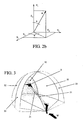
- FIG. 3 describes, in fact, a quarter of a sphere which is the navigation area of the wing airfoil 2, at the centre of which the so-called "powerzone" 31 is defined, in which the wing airfoil 2 expresses the maximum traction on driving cables 21.
- the process according to the present invention by operating through the system 1, can decide if the wing airfoil 2 must perform any one of the possible flight trajectories TV 1 , TV 2 , TV 3 , ..., TV n , starting from the current position at the centre of plane P.
- FIG. 4b For easiness, let us consider in particular FIG. 4b with coordinates related to the wing airfoil 2.
- the Cartesian reference system is integral with the wing airfoil 2 and, with it, it moves into space.
- the wing airfoil 2 is therefore always at the centre of plane P. Only times flow.
- the diagram does not point out the point in which one has to go, since it is a future evaluation.
- the reference system integral with the wing airfoil draws again a "target" which is wholly similar to the previous one, with the only difference that time T 1 has become T 0 , and so on.
- T 1 represents therefore the set of points which can be reached by the wing airfoil 2 in its flight trajectory in 1 step
- T 2 the set of points which can be reached in 2 steps, and so on.
- the wing airfoil 2 is anyway always at the centre of the "target" plane P.
- FIG. 2a and 2b show as an example the "target" plane P till time T 2 , but obviously the number n of steps which can be observed can be different.
- the process according to the present invention uses flight and control parameters.
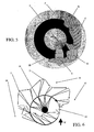
- FIG. 5 shows how the parameters in simplified form change in space, having reduced the complexity of roto-translations of the "carousel" system in a model integral with the reference system of the wing airfoil 2. Morphology and characteristics of such parameters are an essential part of the information which allow the control to decide the flight strategy of the wing airfoil 2.
- the driving unit winches could be subjected to parameters, since they point out the absolute cables length.
- the graph of the height parameter Q represents the optimum area for height problems.
- the graph of the manoeuvre parameter M instead, represents the optimum area to perform the most important manoeuvre in the flight of the wing airfoil 2 defined as azimuth gybing, which consists in a sudden manoeuvre during which the wing airfoil 2 is driven into a quick transition between flight traverses.
- the capability of driving the flight of the wing airfoil 2 allows performing the azimuth gybing, which consists in a quick transition between the two traverses 36 and 38, during which the wing airfoil 2 travels in air a distance equal to at least three times the arc of circumference 34 affected in time in which the "carousel" system 20 travels along such arc.
- the flight control must take care that the manoeuvre, in addition to be quickly performed, has in no way a negative influence in producing energy.
- the position of each wing airfoil is random, namely the image has to be deemed as a top snapshot of the operation of the "carousel" system. In this configuration, each wing airfoil is free of searching the maximum wind intensity, avoiding the exhausted wind front areas for the passage of the immediately previous wing airfoil.
- each graph (height, counterweight, etc.) is proportional to the allowed tolerance to the related parameter.
- Each parameter has in turn a relative weight P Q , P C , P M , P ZI , P T , a relative height with respect to all heights, which will be described below.
- the process has always information available, in a direct form or a form derived from the first and second pieces of information detected by the detecting means of the system 1, related to the flight height of the wing airfoil, to the counterweight dynamics, to traction values, to the safety computation in interdiction areas, to the time in which manoeuvres must be made.
- the most important manoeuvre in the flight of the wing airfoil which has been defined as azimuth gybing. Deciding whether to perform it can be a triggered event: under such conditions, in fact, the process according to the present invention can provide for an emergency step in which the wing airfoil is shown which manoeuvre must be done with maximum priority.
- the process step which decides at every step which direction the flight trajectory of the wing airfoil can take, can be visually represented as a matrix, like the one in the following Table 1, containing, for each parameter, the best coordinates XY at times T 0 , T 1 , T 2 , ... , T n , on the normal plane with respect to the driving cables barycentre.
- the matrix in Table 1 therefore contains desired data.
- the difference between current height and desired height can make one access the numeric controls logic, or the errors computation.
- This characteristic is intrinsic in the matrix: substantially, there are current coordinates and desired coordinates for T 0 , T 1 , T 2 , .... T n . All parameters treated in the matrix create pairs of values XY for a time instant T 0 , T 1 , T 2 , ..., T n .
- the process then photographs the situation in which the wing airfoil is, and transforms the plane P in FIG. 5 into numbers and coordinates.
- the matrix value QX 0 Y 0 points out a point in the neighbourhood of the height parameter, tending to the centre of the graph of height Q in FIG. 5 .
- the circular shape makes all agree in times, in which the trend is clear: rise in T 1 , T 2 .
- the process could already compute the evolution of the ideal point in time: the form of the desired data therefore is not circular.
- the relative weight P Q , P C , P M , P ZI , P T of every related parameter Q, C, M, ZI, T can be settable, and such setting can be dynamic (retroactive).
- the process can be aware of the most difficult parameters to be satisfied.
- a retroactive process corrects the weights of the most critical parameters, in such a way as to make decisions about such parameters more important.
- This type of error can be given a measure, for example a percentage measure, standardised for every parameter with respect to a maximum error value. For example, if in time the counterweight is always outside the dynamics centre and risks to arrive to its end-of-stroke, this standardisation allows locating which is the parameter that makes most mistakes. It can be an independent process which adjusts the weights of each parameter.
- the process provides for a step in which the vector sum of all coordinates at time T 0 is computed.
- the resulting vector is RX 0 Y 0 , which is still not the direction of the flight trajectory in which the wing airfoil has to be moved, since the forecast for the future is still to be considered.
- the process then computes the vectorial sums for all future steps RX 1 Y 1 , RX 2 Y 2 , ... , RX n Y n and time weights PT 0 , PT1 , PT 2 , ... , PT n , are then introduced, which give priority to short-term strategies, at the same time avoiding to take the wing airfoil in potentially critical areas.
- time weights PT 0 , PT 1 , PT 2 , ..., PT n can be settable.
- the process according to the present invention locates an ideal instantaneous coordinate (target) to which one tends with the manoeuvre of the wing airfoil along its flight trajectory. Once having found the ideal coordinate, it is necessary to take care of the manoeuvre and of the control of the driving cables in order to make the wing airfoil reach its target.
- the process then comprises a step of choosing the best path (shortest path, by-passing the interdiction areas, etc.) in order to take the wing airfoil from the current position to the target.
- the process decides, depending on the target to be reached, the best flight trajectory for reaching it minimising the time, since being with the wing airfoil always correctly on the target sequence located as best, is a guarantee of producing the maximum energy under maximum safety and the maximum compliance with dynamic specifications.
- the heart of the problem in this step is how transferring the target coordinates in traction.
- the step of choosing the best path therefore uses an Inertial Navigation System (INS) supported by a dynamic model of the wing airfoil (FVM) taking into account wing airfoil flight equations and inertias, together with the percentage of reaction which it can have depending on the traction differential on cables.
- INS Inertial Navigation System
- FVM dynamic model of the wing airfoil
- Inertias and traction describe the manoeuvre law of the wing airfoil; it is suitable to take into account the (predictive) evaluations of the best path, by evaluating all possible paths and evaluating the manoeuvre with a decision tree. In this step, apparent speeds and tractions are taken into account, and one is able to accurately evaluate the best path strategy.
- Synergy between inertial navigation and information given by dynamic modelling, namely the motion model obtained from the history of the wing airfoil positions, from control inputs and from forces operating on the wing airfoil itself have been widely demonstrated in the past by using dynamic equations of the vehicle (for example by Koifman and Bar-Itzhack, 1999; Ma et al., 2003). These studies demonstrate that the main advantage in using a vehicle model is the improvement of the capability to observe the error sources in the INS.
- n [N, E, D] (North, East, Down)
- g n the gravity acceleration
- f b the acceleration vector on the three axes
- ⁇ b the rotation.
- C n b and E n b are respectively the transformation and rotation matrices, defined as follows:
- the dynamic model of the wing airfoil (FVM) with six degrees of freedom is instead composed of a set of equations which provide for state variables of the wing airfoil, composed of position, speed, Eulero angles and rotations by means of the control variables of the wing airfoil, which are assumed as known from system 1.
- the movement of the wing airfoil can be described by the following system of movement equations, in which the forces operating on the vehicle are function of wing airfoil position, speed, Eulero angles and current rotation:
- q ⁇ C 7 ⁇ pr - C 6 ⁇ p 2 - r 2 + C 5 ⁇ M
- r ⁇ C 9 ⁇ pq - C 3 ⁇ qr + C 2 ⁇ l + C 8 ⁇ N
- v b [u, v, w] are the speed components along the three axe
- g x , g y , g z are the components of the gravity acceleration vector decomposed in the wing airfoil reference system, whose mass is designated as m.
- Coefficients C 0-9 are obtained starting from the inertia matrix I.
- a first method implies the comparison and correction of speed and attitude of the wing airfoil such as are obtained, independently, from INS and from FVM.
- the second method uses the acceleration and rotation forecast performed by the FVM in order to realise a direct calibration of the Inertial Measuring Unit (IMU).
- IMU Inertial Measuring Unit
- the INS processes wing airfoil position, speed and Eulero angles (which describe the rotation) for integrating acceleration and rotation measures provided by the IMU on board the wing airfoil.
- the wing airfoil model computes wing airfoil speed and angles by using the control inputs of the aircraft itself.
- the real implementation of FMV and INS takes advantage from the application of the most recent developments of the mathematics based on quaternions.
- Task of an Extended Kalman Filter (EKF) is evaluating INS and FVM errors by observing the differences between speed and angles data respectively produced by INS and FVM.
- the FMV is used for computing acceleration and rotation estimation directly from control inputs.
- the input of the Extended Kalman Filter is therefore composed of differences between acceleration and rotation estimations computed by FVM and those read from used sensors.
- the EKF is therefore used for estimating acceleration and rotation errors of sensors and FVM, which are then used for consequently correcting sensors and FVM.
- the wing airfoil manoeuvre has however the problem of being calibrated. It is true that one can decide the amount of manoeuvre, but the amount remains to be defined. There is in fact the risk of oscillating, in an excessive gain, due to inertial causes, kinematic chain elasticity (winches are on the ground, the manoeuvre occurs in air) and measurement delay (neglectable). There is therefore the risk of performing non-calibrated, insufficient or exaggerated manoeuvres, which compel to perform continuous corrections (opposite compensation), with the risk of uncontrollably oscillating.
- the control art has already devised techniques such as Hinf and the already mentioned Kalman Filters, which consider the actuation delay as one of the disturbances, one of the noises which the control must manage, by optimising the manoeuvre and limiting it with filters and methodologies which are calibrated on the system or self-calibrating.
- the described process according to the present invention can be equipped with predictive capabilities whose time depth is function of the information processing power of the system according to the present invention.
- the other major characteristic which allows forecasting the above described problems is that the processing and controlling means receive acceleration-related information.
- the process according to the present invention therefore comprises the steps of:
Landscapes
- Engineering & Computer Science (AREA)
- Life Sciences & Earth Sciences (AREA)
- Sustainable Development (AREA)
- Sustainable Energy (AREA)
- Chemical & Material Sciences (AREA)
- Combustion & Propulsion (AREA)
- Mechanical Engineering (AREA)
- General Engineering & Computer Science (AREA)
- Aviation & Aerospace Engineering (AREA)
- Remote Sensing (AREA)
- Radar, Positioning & Navigation (AREA)
- Physics & Mathematics (AREA)
- General Physics & Mathematics (AREA)
- Automation & Control Theory (AREA)
- Toys (AREA)
- Control Of Position, Course, Altitude, Or Attitude Of Moving Bodies (AREA)
- Turbine Rotor Nozzle Sealing (AREA)
- Control Of Electric Motors In General (AREA)
- Lining Or Joining Of Plastics Or The Like (AREA)
- Aerodynamic Tests, Hydrodynamic Tests, Wind Tunnels, And Water Tanks (AREA)
- Wind Motors (AREA)
- Earth Drilling (AREA)
Claims (37)
- Vorrichtung für die Erzeugung von elektrischer Energie, die folgendes einschließt:- mindestens ein leistungsstarkes Flügelprofil (2);- eine Bedienungseinheit (9), die mit zwei Winden ausgestattet ist, mit denen das genannte leistungsstarke Flügelprofil (2) durch die beiden entsprechenden Bedienungskabel (21) verbunden ist;- ein System (1) für die automatische Steuerung des Fluges des genannten mindestens einem leistungsstarken Flügelprofils (2), und dadurch gekennzeichnet ist, dass das genannte System außerdem folgendes einschließt:- Erste Erfassungsgeräte (3) am genannten leistungsstarken Flügelprofil (2), die dazu dienen, die ersten Informationen (3a) zu erfassen, welche mindestens eine Position und eine Raumausrichtung des genannten leistungsstarken Flügelprofils (2) und die Beschleunigungen, denen das genannte leistungsstarke Flügelprofil (2) ausgesetzt wird, betreffen;- Zweite Erfassungsgeräte (5) am Boden, die dazu dienen, die zweiten Informationen (5a) zu erfassen, die mindestens eine Spannungsgröße an den genannten Bedienungskabeln (21) des genannten leistungsstarken Flügelprofils (2) und eine Position eines Gegengewichtes der genannten Bedienungseinheit (9) betreffen;- Bearbeitungs- und Steuergeräte (7) der genannten ersten (3a) und der genannten zweiten (5a) Informationen, die dazu dienen, den Inhalt der genannten Informationen (3a, 5a) in eine mechanische Steuerung umzuwandeln, welche auf die genannten Winden der genannten Bedienungseinheit (9) einwirkt, um das genannte leistungsstarke Flügelprofil (2) längs einer Flugbahn TV1, TV2, TV3, ..., TVn zu manövrieren, die einen "Lifteffekt" maximiert, welcher am genannten leistungsstarken Flügelprofil (2) durch einen Windstrom W erzeugt wird, in den eine kinetische Energiemenge eingetaucht und maximiert wird, welche dem genannten Windstrom W entzogen wird; und- Ein Übertragungssystem der genannten ersten Informationen (3a) an die genannten Bearbeitungs- und Steuergeräte (7).
- System (1) gemäß Patentanspruch 1, das dadurch gekennzeichnet ist, dass die genannten Bearbeitungs- und Steuergeräte (7) einen geometrischen Motor (7a) einschließen, der dazu dient, die genannten ersten Informationen (3a) zu bearbeiten, um Informationen (7c) über die Position, Beschleunigung und Ausrichtung des genannten Flügelprofils (2) an eine numerische Steuerung (7b) zurückzuerstatten, die dazu dient (9a), auf die genannten Winden der genannten Bedienungseinheit (9) einzuwirken, um eine Traktionskraft an den genannten Bedienungskabeln (21) zu steuern.
- System (1) gemäß Patentanspruch 2, das dadurch gekennzeichnet ist, dass das genannte Übertragungssystem die genannten ersten Informationen (3a) an den genannten geometrischen Motor (7a) überträgt.
- System (1) gemäß Patentanspruch 1, das dadurch gekennzeichnet ist, dass es eine Steuerung für die Dissipation der Instabilität enthält.
- System (1) gemäß Patentanspruch 1, das dadurch gekennzeichnet ist, dass die genannten ersten Erfassungsgeräte (3) dreiachsige Beschleunigungsmesser enthalten.
- System (1) gemäß Patentanspruch 5, das dadurch gekennzeichnet ist, dass die genannten dreiachsigen Beschleunigungsmesser vom Typ MEMS sind.
- System (1) gemäß Patentanspruch 1, das dadurch gekennzeichnet ist, dass die genannten ersten Erfassungsgeräte (3) einen Erdinduktionskompass enthalten.
- System (1) gemäß Patentanspruch 7, das dadurch gekennzeichnet ist, dass der genannte Erdinduktionskompass ein Fluxgate Magnetometer ist.
- System (1) gemäß Patentanspruch 5, das dadurch gekennzeichnet ist, dass jeder der beiden genannten dreiachsigen Beschleunigungsmesser am entsprechenden Endstück des genannten Flügelprofils (2) an einer Verbindung der beiden Bedienungskabel (21) mit den Wänden des genannten Flügelprofils (2) angebracht ist.
- System (1) gemäß Patentanspruch 1, das dadurch gekennzeichnet ist, dass die genannten zweiten Erfassungsgeräte (5) Dehnungsmessstreifen enthalten, die dazu dienen, eine Ablenkung der genannten Bedienungskabel (21) zu messen.
- System (1) gemäß Patentanspruch 1, das dadurch gekennzeichnet ist, dass die genannten zweiten Erfassungsgeräte (5) Encoder an den genannten Winden der genannten Bedienungseinheit (9) enthalten.
- System (1) gemäß Patentanspruch 1, das dadurch gekennzeichnet ist, dass die genannten zweiten Erfassungsgeräte (5) Annäherungssensoren enthalten.
- System (1) gemäß Patentanspruch 1, das dadurch gekennzeichnet ist, dass die genannten zweiten Erfassungsgeräte (5) ein künstliches Sichtsystem am Boden enthalten.
- System (1) gemäß Patentanspruch 1, das dadurch gekennzeichnet ist, dass das genannte Flügelprofil (2) aus Rheologiepolymeren realisiert ist.
- System (1) gemäß Patentanspruch 1, das dadurch gekennzeichnet ist, dass die genannten ersten (3) und/oder zweiten (5) Erfassungsgeräte virtuelle Sensoren enthalten.
- System (1) gemäß Patentanspruch 1, das dadurch gekennzeichnet ist, dass das genannte Übertragungssystem durch mindestens eine optische Datenfaser in den genannten Bedienungskabeln (21) des genannten Flügelprofils (2) integriert wird.
- System (1) gemäß Patentanspruch 1 oder 16, das dadurch gekennzeichnet ist, dass die genannten Bedienungskabel (21) einen Abschnitt in Form eines Flügelprofils haben.
- System (1) gemäß Patentanspruch 1, das dadurch gekennzeichnet ist, dass das genannte Übertragungssystem mit Funkfrequenz erfolgt.
- System (1) gemäß Patentanspruch 1, das dadurch gekennzeichnet ist, dass das genannte Übertragungssystem mit Ultraschall erfolgt.
- System (1) gemäß Patentanspruch 1, das dadurch gekennzeichnet ist, dass für das genannte Übertragungssystem ein verbindungsorientiertes Datenstromprotokoll verwendet wird.
- System (1) gemäß Patentanspruch 1, das dadurch gekennzeichnet ist, dass für das genannte Übertragungssystem ein paketbasiertes Protokoll verwendet wird.
- System (1) gemäß Patentanspruch 1, das dadurch gekennzeichnet ist, dass für das genannte Übertragungssystem ein asynchrones Datenprotokoll verwendet wird.
- System (1) gemäß Patentanspruch 1, das dadurch gekennzeichnet ist, dass es Vorbearbeitungsgeräte (11) enthält, die dazu dienen, eine Vorbearbeitung aller oder eines Teils der genannten ersten Informationen (3a) am genannten Flügelprofil (2) auszuführen, um die ersten vorbearbeiteten Informationen (3a') zu liefern.
- System (1) gemäß Patentanspruch 1, das dadurch gekennzeichnet ist, dass es mindestens ein Versorgungssystem der genannten ersten Erfassungsgeräte (3) und des genannten Übertragungssystems am Flügelprofil (2) enthält.
- System (1) gemäß Patentanspruch 24, das dadurch gekennzeichnet ist, dass das genannte Versorgungssystem photovoltaische Dünnschichtmodule am Kunststoffträger enthält, die am genannten Flügelprofil (2) angebracht sind.
- System (1) gemäß Patentanspruch 24, das dadurch gekennzeichnet ist, dass das genannte Versorgungssystem eine Mikro-Windturbine enthält, die mit einem Dauermagnetgenerator verbunden ist.
- Automatisches Kontrollverfahren der Vorrichtung gemäß einem beliebigen der vorhergehenden Patentansprüche, das dadurch gekennzeichnet ist, dass es aus folgenden Phasen besteht:a) Erfassung der genannten ersten Informationen (3a) eines aktuellen Moments einer Flugbahn des genannten Flügelprofils (2) durch die genannten ersten Erfassungsgeräte (3) ;b) Erfassung der genannten zweiten Informationen (5a) eines aktuellen Moments einer Flugbahn des genannten Flügelprofils (2) durch die genannten zweiten Erfassungsgeräte (5a);c) Sendung der genannten ersten Informationen (3a, 3a') durch das genannte Übertragungssystem an die genannten Bearbeitungs- und Steuergeräte (7);d) Sendung der genannten zweiten Informationen (5a) an die genannten Bearbeitungs- und Steuergeräte (7);e) Direkt oder indirekt aus den genannten ersten (3a, 3a') und zweiten Informationen Werte für mindestens eine aktuelle Position XY und die aktuelle Flughöhe des genannten Flügelprofils (2), für die Dynamik des genannten Gegengewichtes und für die Traktion an den genannten Bedienungskabeln (21) erhalten;f) Definition der Flug- und Kontrollparameter;g) Definition eines Gewichtes für PQ, PC, PM, PZI, PT, für jeden der genannten Flug- und Kontrollparameter;h) Berechnung der besten XY-Koordinaten für jeden der genannten Parameter in nachfolgenden Zeiten T0, T1, T2, ..., Tn;i) Berechnung einer vektoriellen Summe RX0Y0 aller Koordinaten in der genannten Zeit T0;j) Berechnung der vektoriellen Summen RX1Y1, RX2Y2, ..., RXnYn für alle zukünftigen Schritte T1, T2, ..., Tn;k) Definition und Anwendung der zeitlichen Gewichte PT0, PT1, PT2, ..., PTn für die genannten vektoriellen Summen;l) Auswahl der besten vektoriellen Summe aus RX1Y1, RX2Y2, ..., RXnYn als ideale Momentankoordinate (Target), zu der mit einer Bedienung des genannten Flügelprofils (2) tendiert wird;m) Auswahl der besten Flugbahnstrecke TV1, TV2, TV3, ..., TVn, um das genannte Flügelprofil (2) von der genannten aktuellen Position auf das genannte Target zu bringen;n) Führung des genannten Flügelprofils (2) von den genannten Koordinaten der genannten aktuellen Position auf das genannte Target durch Einwirken auf die genannte Bedienungseinheit (9) durch die genannte numerische Steuerung (7b);o) Die Phasen von a) bis n) in jedem Zeitintervall Δt wiederholen.
- Verfahren gemäß Patentanspruch 27, das dadurch gekennzeichnet ist, dass es zwischen der Phase a) und der Phase b) die Phase für die Neubearbeitung aller oder eines Teils der genannten ersten Informationen (3a) durch die genannten Vorbearbeitungsgeräte (11) enthält, um die genannten ersten vorbearbeiteten Informationen (3a') zu erhalten.
- Verfahren gemäß Patentanspruch 27, das dadurch gekennzeichnet ist, dass die genannten Flug- und Kontrollparameter der Wert Q, die Dynamik des Gegengewichtes C, das Manöver M, die Sperrzonen ZI, die Traktion T der genannten Bedienungskabel (21) sind.
- Verfahren gemäß Patentanspruch 27, das dadurch gekennzeichnet ist, dass die genannte Phase f) die Phase zur Definition einer Toleranz für jeden der entsprechenden Parameter einschließt.
- Verfahren gemäß Patentanspruch 27, das dadurch gekennzeichnet ist, dass für die genannte Phase m) ein Trägheitsnavigationssystem (INS) verwendet wird, das durch ein dynamisches Modell des genannten Flügelprofils (FVM) unterstützt wird.
- Verfahren gemäß Patentanspruch 27, das dadurch gekennzeichnet ist, dass es eine Notphase einschließt, um dem Flügelprofil anzuzeigen, welche Bedienung mit maximaler Priorität ausgeführt werden muss.
- Verfahren gemäß Patentanspruch 27, das dadurch gekennzeichnet ist, dass es die rückwirkende Korrekturphase der genannten Flug- und Kontrollparameter einschließt.
- Verfahren gemäß Patentanspruch 27, das dadurch gekennzeichnet ist, dass es die Kalibrationsphase der genannten Bedienung durch Hinf- und/oder Kalman-Filter-Techniken einschließt.
- Verfahren gemäß Patentanspruch 27, das dadurch gekennzeichnet ist, dass es die rückwirkende Einstellungsphase für die Dauer des genannten Zeitintervalls Δt einschließt.
- Verwendung eines Systems (1) gemäß einem beliebigen Patentanspruch von 1 bis 26 zusammen mit einem "Karussellsystem" (20).
- Verwendung eines Verfahrens gemäß einem beliebigen Patentanspruch von 27 bis 35 zusammen mit einem "Karussellsystem" (20).
Priority Applications (2)
| Application Number | Priority Date | Filing Date | Title |
|---|---|---|---|
| PL06756283T PL2016284T3 (pl) | 2006-05-10 | 2006-05-10 | Urządzenie do wytwarzania energii elektrycznej i proces automatycznego sterowania wymienionym urządzeniem |
| CY20121101093T CY1113467T1 (el) | 2006-05-10 | 2012-11-14 | Μια συσκευη για την παραγωγη ηλεκτρικης ενεργειας και διαδικασια για τον αυτοματο ελεγχο της εν λογω συσκευης |
Applications Claiming Priority (1)
| Application Number | Priority Date | Filing Date | Title |
|---|---|---|---|
| PCT/IT2006/000343 WO2007129341A1 (en) | 2006-05-10 | 2006-05-10 | System and process for automatically controlling the flight of power wing airfoils |
Publications (2)
| Publication Number | Publication Date |
|---|---|
| EP2016284A1 EP2016284A1 (de) | 2009-01-21 |
| EP2016284B1 true EP2016284B1 (de) | 2012-08-15 |
Family
ID=37635646
Family Applications (1)
| Application Number | Title | Priority Date | Filing Date |
|---|---|---|---|
| EP06756283A Active EP2016284B1 (de) | 2006-05-10 | 2006-05-10 | Vorrichtung zur erzeugung von elektrischen energie sowie verfahren zur steuerung dieser vorrichtung |
Country Status (20)
| Country | Link |
|---|---|
| US (1) | US8152106B2 (de) |
| EP (1) | EP2016284B1 (de) |
| JP (1) | JP4951061B2 (de) |
| KR (1) | KR101273565B1 (de) |
| CN (1) | CN101460735B (de) |
| AU (1) | AU2006343138B2 (de) |
| BR (1) | BRPI0621662B1 (de) |
| CA (1) | CA2651379C (de) |
| CY (1) | CY1113467T1 (de) |
| DK (1) | DK2016284T3 (de) |
| ES (1) | ES2393202T3 (de) |
| IL (1) | IL194842A (de) |
| MX (1) | MX2008014308A (de) |
| NO (1) | NO339388B1 (de) |
| NZ (1) | NZ572215A (de) |
| PL (1) | PL2016284T3 (de) |
| PT (1) | PT2016284E (de) |
| TN (1) | TNSN08452A1 (de) |
| UA (1) | UA89001C2 (de) |
| WO (1) | WO2007129341A1 (de) |
Families Citing this family (22)
| Publication number | Priority date | Publication date | Assignee | Title |
|---|---|---|---|---|
| ITBS20080157A1 (it) * | 2008-08-26 | 2010-02-27 | Orlando Lozzi | Rotore eolico multipale ad asse verticale autoavviante, con orientamento continuo degli angoli di incidenza, determinati gestiti e controllati da un sistema elettronico |
| ITTO20090008U1 (it) | 2009-01-23 | 2010-07-24 | Massimo Ippolito | Fune per generatore eolico troposferico. |
| RU2441809C2 (ru) * | 2009-12-11 | 2012-02-10 | Открытое Акционерное Общество "Московский Вертолетный Завод Им. М.Л. Миля" | Способ управления беспилотным привязным летательным аппаратом и беспилотный авиационный комплекс |
| WO2011076270A1 (en) | 2009-12-22 | 2011-06-30 | Philippe Dubois | Stabilization and orientation control mechanisms for wings or power kites including a wing |
| CN102536646B (zh) * | 2010-12-09 | 2014-02-19 | 三一电气有限责任公司 | 风力发电机组及其控制系统 |
| US9080550B2 (en) | 2011-11-30 | 2015-07-14 | Leonid Goldstein | Airborne wind energy conversion system with fast motion transfer |
| WO2013124522A1 (en) * | 2012-02-22 | 2013-08-29 | Nokia Corporation | A system, and a method for providing a predition for controlling a system |
| CN103277253B (zh) * | 2012-02-29 | 2015-02-25 | 南通大学 | 高风能捕获效率的垂直轴风力机旋转主轴振颤抑制方法 |
| CN102914284B (zh) * | 2012-10-19 | 2015-07-08 | 中铁隧道集团有限公司 | 一种作业臂工位的实时测量系统及其测量方法 |
| US9056677B1 (en) * | 2013-12-19 | 2015-06-16 | Google Inc. | Curvature sensing |
| US9704268B2 (en) * | 2014-01-09 | 2017-07-11 | Avago Technologies General Ip (Singapore) Pte. Ltd. | Determining information from images using sensor data |
| US9625913B2 (en) * | 2014-12-09 | 2017-04-18 | Embry-Riddle Aeronautical University, Inc. | System and method for robust nonlinear regulation control of unmanned aerial vehicles synthetic jet actuators |
| CN105604807B (zh) * | 2015-12-31 | 2019-02-15 | 北京金风科创风电设备有限公司 | 风电机组监测方法及装置 |
| KR101686929B1 (ko) * | 2016-05-03 | 2016-12-15 | 엘아이지넥스원 주식회사 | 비행체의 구동 날개 얼라인먼트 장치 및 방법 |
| CN106428553B (zh) * | 2016-09-30 | 2018-09-07 | 襄阳宏伟航空器有限责任公司 | 一种柔翼无人机可变速航向控制装置及方法 |
| CN110719874B (zh) * | 2017-06-01 | 2023-07-04 | 罗马里斯公司 | 带有同步传感器网络的无人驾驶飞机 |
| CN107688685B (zh) * | 2017-07-03 | 2020-04-21 | 西北工业大学 | 一种局部空间电梯系统系绳内部张力预测方法 |
| EP3658456A4 (de) | 2017-07-27 | 2021-04-21 | Skyryse, Inc. | System und verfahren für situationsbewusstsein, fahrzeugsteuerung und/oder kontingenzplanung |
| US11484381B2 (en) * | 2018-06-21 | 2022-11-01 | Ruthless, LLC | Instrument alignment feedback system and method |
| TWI871364B (zh) | 2019-10-08 | 2025-02-01 | 卡爾頓 E 史賓德 | 量測角定向而有助於手術過程之jamshidi針系統及使用其執行手術之方法 |
| US20210246875A1 (en) * | 2020-02-06 | 2021-08-12 | General Electric Company | System and method for optimizing wake management in wind farms |
| US12066010B2 (en) | 2022-04-04 | 2024-08-20 | Ge Infrastructure Technology Llc | Method and system for determining and tracking wind turbine tower deflection |
Family Cites Families (24)
| Publication number | Priority date | Publication date | Assignee | Title |
|---|---|---|---|---|
| US3227398A (en) * | 1965-03-04 | 1966-01-04 | Jr Arthur D Struble | Balloon tether cable |
| US4124182A (en) * | 1977-11-14 | 1978-11-07 | Arnold Loeb | Wind driven energy system |
| BE884431A (fr) * | 1979-07-19 | 1981-01-23 | Jones Andrew W | Structure de voilure |
| GB8907513D0 (en) | 1989-04-04 | 1989-05-17 | Loader Charles S | Pig farrowing and weaning apparatus |
| GB8907889D0 (en) * | 1989-04-07 | 1989-05-24 | Kirby John | Flying generator |
| DE4007159A1 (de) * | 1989-06-06 | 1990-12-13 | Christian Kunze | Lenkbarer flachdrachen |
| JPH04237877A (ja) * | 1991-01-18 | 1992-08-26 | Junichi Miyashita | 揚力体を用いた風力発電装置 |
| DE19524938A1 (de) * | 1995-07-08 | 1997-01-09 | Bosch Gmbh Robert | Adaptive Getriebesteuerung |
| NL1004508C2 (nl) * | 1996-11-12 | 1998-05-14 | Wubbo Johannes Ockels | Windgedreven aandrijfinrichting. |
| JPH11124095A (ja) * | 1997-10-22 | 1999-05-11 | Keigoro Shigiyama | 高空偏西風利用係留滑空体 |
| US5931416A (en) * | 1997-11-21 | 1999-08-03 | Carpenter; Howard G. | Tethered aircraft having remotely controlled angle of attack |
| JPH11252893A (ja) * | 1998-01-02 | 1999-09-17 | Toshiyasu Suzuki | 流体発電装置、風力発電装置、流体発電装置および 風力発電装置 |
| US6254034B1 (en) * | 1999-09-20 | 2001-07-03 | Howard G. Carpenter | Tethered aircraft system for gathering energy from wind |
| US6523781B2 (en) * | 2000-08-30 | 2003-02-25 | Gary Dean Ragner | Axial-mode linear wind-turbine |
| US6578797B2 (en) * | 2001-08-06 | 2003-06-17 | David C. Fischer | Kite altitude measuring apparatus |
| ITTO20030945A1 (it) | 2003-11-26 | 2004-02-25 | Sequoia Automation S R L | Sistema di controllo intelligente che sfrutta le caratteristiche di un'ala, aquilone o vela in genere per produrre energia, permettendo configurazioni multiple e la realizzazione di impianti ad alto potenziale. |
| DE202004013841U1 (de) * | 2004-09-06 | 2006-01-19 | Skysails Gmbh & Co. Kg | Wasserfahrzeug mit einem drachenartigen Element |
| DE102004018838A1 (de) * | 2004-04-19 | 2005-11-03 | Skysails Gmbh | Positionierungsvorrichtung für ein frei ausfliegendes drachenartiges Windangriffselement bei einem Wasserfahrzeug mit Windantrieb |
| DE102004018814A1 (de) * | 2004-04-19 | 2005-11-03 | Skysails Gmbh | Setzsystem für ein ausfliegendes drachenartiges Windangriffselement bei einem Wasserfahrzeug mit Windantrieb |
| DE102004018837A1 (de) * | 2004-04-19 | 2005-11-03 | Skysails Gmbh | Wasserfahrzeug mit einem frei ausfliegenden drachenartigen Windangriffselement als Windantrieb |
| ES2301919T3 (es) | 2004-12-03 | 2008-07-01 | Massimo Ippolito | Turbina eolica de eje vertical con sistema de control para cometa de direccion. |
| DE202006005389U1 (de) * | 2006-03-31 | 2007-08-02 | Skysails Gmbh & Co. Kg | Windenergieanlage mit steuerbarem Drachen |
| JP4208153B2 (ja) * | 2006-10-06 | 2009-01-14 | 保信 刀祢明 | 発電装置 |
| US7656053B2 (en) * | 2007-08-03 | 2010-02-02 | Makani Power, Inc. | Controlling power extraction for wind power generation |
-
2006
- 2006-05-10 PL PL06756283T patent/PL2016284T3/pl unknown
- 2006-05-10 PT PT06756283T patent/PT2016284E/pt unknown
- 2006-05-10 NZ NZ572215A patent/NZ572215A/en not_active IP Right Cessation
- 2006-05-10 JP JP2009508678A patent/JP4951061B2/ja not_active Expired - Fee Related
- 2006-05-10 MX MX2008014308A patent/MX2008014308A/es active IP Right Grant
- 2006-05-10 ES ES06756283T patent/ES2393202T3/es active Active
- 2006-05-10 CA CA2651379A patent/CA2651379C/en not_active Expired - Fee Related
- 2006-05-10 CN CN200680054960XA patent/CN101460735B/zh not_active Expired - Fee Related
- 2006-05-10 BR BRPI0621662-5A patent/BRPI0621662B1/pt not_active IP Right Cessation
- 2006-05-10 US US12/297,948 patent/US8152106B2/en not_active Expired - Fee Related
- 2006-05-10 DK DK06756283.5T patent/DK2016284T3/da active
- 2006-05-10 AU AU2006343138A patent/AU2006343138B2/en not_active Ceased
- 2006-05-10 WO PCT/IT2006/000343 patent/WO2007129341A1/en not_active Ceased
- 2006-05-10 EP EP06756283A patent/EP2016284B1/de active Active
- 2006-05-10 KR KR1020087027037A patent/KR101273565B1/ko not_active Expired - Fee Related
- 2006-10-05 UA UAA200812976A patent/UA89001C2/uk unknown
-
2008
- 2008-10-22 IL IL194842A patent/IL194842A/en not_active IP Right Cessation
- 2008-11-10 TN TNP2008000452A patent/TNSN08452A1/en unknown
- 2008-12-10 NO NO20085139A patent/NO339388B1/no not_active IP Right Cessation
-
2012
- 2012-11-14 CY CY20121101093T patent/CY1113467T1/el unknown
Also Published As
| Publication number | Publication date |
|---|---|
| AU2006343138A1 (en) | 2007-11-15 |
| PT2016284E (pt) | 2012-11-29 |
| KR101273565B1 (ko) | 2013-06-10 |
| US20090090815A1 (en) | 2009-04-09 |
| PL2016284T3 (pl) | 2013-02-28 |
| NO339388B1 (no) | 2016-12-05 |
| CA2651379C (en) | 2013-08-06 |
| KR20090034801A (ko) | 2009-04-08 |
| UA89001C2 (uk) | 2009-12-10 |
| ES2393202T3 (es) | 2012-12-19 |
| NO20085139L (no) | 2009-02-10 |
| TNSN08452A1 (en) | 2010-04-14 |
| BRPI0621662B1 (pt) | 2018-05-15 |
| CN101460735B (zh) | 2013-06-26 |
| CN101460735A (zh) | 2009-06-17 |
| AU2006343138B2 (en) | 2011-11-03 |
| US8152106B2 (en) | 2012-04-10 |
| JP4951061B2 (ja) | 2012-06-13 |
| IL194842A (en) | 2011-08-31 |
| WO2007129341A1 (en) | 2007-11-15 |
| JP2009536131A (ja) | 2009-10-08 |
| MX2008014308A (es) | 2008-11-18 |
| BRPI0621662A2 (pt) | 2011-12-20 |
| NZ572215A (en) | 2010-07-30 |
| DK2016284T3 (da) | 2012-12-03 |
| IL194842A0 (en) | 2009-08-03 |
| CY1113467T1 (el) | 2016-06-22 |
| CA2651379A1 (en) | 2007-11-15 |
| EP2016284A1 (de) | 2009-01-21 |
Similar Documents
| Publication | Publication Date | Title |
|---|---|---|
| EP2016284B1 (de) | Vorrichtung zur erzeugung von elektrischen energie sowie verfahren zur steuerung dieser vorrichtung | |
| Espinoza et al. | Backstepping-sliding mode controllers applied to a fixed-wing UAV | |
| US8366055B2 (en) | Controllable miniature mono-wing aircraft | |
| Baayen et al. | Tracking control with adaption of kites | |
| CN104765272A (zh) | 一种基于pid神经元网络控制(pidnn)的四旋翼飞行器控制方法 | |
| CN205899386U (zh) | 多旋翼无人机飞行用外置式安全控制装置及系统 | |
| CN106444800A (zh) | 多旋翼无人机飞行用外置式安全控制装置、方法及系统 | |
| CN106406340A (zh) | 四旋翼无人飞行器及其控制方法 | |
| Ioppo | The design, modelling and control of an autonomous tethered multirotor UAV | |
| Qu et al. | Wind estimation using the position information from a hovering quadrotor | |
| RU2405716C2 (ru) | Система и процесс для автоматического управления полетом аэродинамических поверхностей силового крыла | |
| Hamada et al. | Development of an Unmanned Aerial Vehicle (UAV) research platform for flutter analysis | |
| CN121115832B (zh) | 多旋翼无人机飞行控制器的姿态解算方法 | |
| Grauer et al. | Development of a Sensor Suite for a Flapping-Wing UAV Platform | |
| Zhang et al. | A novel Micro Air Vehicle with flexible wing integrated with on-board electronic devices | |
| Grauer et al. | System identification of an ornithopter aerodynamics model | |
| Donnelly | Dynamics and control of a single-line maneuverable kite | |
| Oh et al. | Experimental framework for controller design of a rotorcraft unmanned aerial vehicle using multi-camera system | |
| Yeung | Wind Gust Measuring at Low Altitude Using an Unmanned Aerial System | |
| Khorani et al. | An IMU-based system identification technique for quadrotors | |
| Nshuti | Design of Flight Control Laws for a Novel Stratospheric Dual-Aircraft Platform | |
| CN121305963A (zh) | 基于动态风场建模的无人机高精度模拟训练方法及系统 | |
| Koçer | Full-Scale Wind Turbine Flow Field Measurements Using an Instrumented Uninhabited Aerial Vehicle | |
| Kunzmann et al. | Investigation in the control of a four-rotor aerial robot | |
| Jiang et al. | Control Algorithm for Planning Path of Unmanned Aircraft |
Legal Events
| Date | Code | Title | Description |
|---|---|---|---|
| PUAI | Public reference made under article 153(3) epc to a published international application that has entered the european phase |
Free format text: ORIGINAL CODE: 0009012 |
|
| 17P | Request for examination filed |
Effective date: 20081030 |
|
| AK | Designated contracting states |
Kind code of ref document: A1 Designated state(s): AT BE BG CH CY CZ DE DK EE ES FI FR GB GR HU IE IS IT LI LT LU LV MC NL PL PT RO SE SI SK TR |
|
| AX | Request for extension of the european patent |
Extension state: AL BA HR MK YU |
|
| GRAP | Despatch of communication of intention to grant a patent |
Free format text: ORIGINAL CODE: EPIDOSNIGR1 |
|
| RTI1 | Title (correction) |
Free format text: A DEVICE FOR THE PRODUCTION OF ELECTRIC ENERGY AND PROCESS FOR THE AUTOMATIC CONTROL OF SAID DEVICE |
|
| RAX | Requested extension states of the european patent have changed |
Extension state: AL Payment date: 20081030 Extension state: HR Payment date: 20081030 |
|
| GRAS | Grant fee paid |
Free format text: ORIGINAL CODE: EPIDOSNIGR3 |
|
| GRAA | (expected) grant |
Free format text: ORIGINAL CODE: 0009210 |
|
| AK | Designated contracting states |
Kind code of ref document: B1 Designated state(s): AT BE BG CH CY CZ DE DK EE ES FI FR GB GR HU IE IS IT LI LT LU LV MC NL PL PT RO SE SI SK TR |
|
| AX | Request for extension of the european patent |
Extension state: AL HR |
|
| REG | Reference to a national code |
Ref country code: AT Ref legal event code: REF Ref document number: 570984 Country of ref document: AT Kind code of ref document: T Effective date: 20120815 Ref country code: CH Ref legal event code: EP Ref country code: GB Ref legal event code: FG4D |
|
| REG | Reference to a national code |
Ref country code: IE Ref legal event code: FG4D |
|
| REG | Reference to a national code |
Ref country code: DE Ref legal event code: R096 Ref document number: 602006031446 Country of ref document: DE Effective date: 20121018 |
|
| REG | Reference to a national code |
Ref country code: CH Ref legal event code: NV Representative=s name: MEYER AND KOLLEGEN, CH |
|
| REG | Reference to a national code |
Ref country code: RO Ref legal event code: EPE |
|
| REG | Reference to a national code |
Ref country code: PT Ref legal event code: SC4A Free format text: AVAILABILITY OF NATIONAL TRANSLATION Effective date: 20121114 |
|
| REG | Reference to a national code |
Ref country code: DK Ref legal event code: T3 |
|
| REG | Reference to a national code |
Ref country code: NL Ref legal event code: T3 |
|
| REG | Reference to a national code |
Ref country code: SE Ref legal event code: TRGR |
|
| REG | Reference to a national code |
Ref country code: ES Ref legal event code: FG2A Ref document number: 2393202 Country of ref document: ES Kind code of ref document: T3 Effective date: 20121219 |
|
| REG | Reference to a national code |
Ref country code: EE Ref legal event code: FG4A Ref document number: E007463 Country of ref document: EE Effective date: 20121115 |
|
| PG25 | Lapsed in a contracting state [announced via postgrant information from national office to epo] |
Ref country code: SI Free format text: LAPSE BECAUSE OF FAILURE TO SUBMIT A TRANSLATION OF THE DESCRIPTION OR TO PAY THE FEE WITHIN THE PRESCRIBED TIME-LIMIT Effective date: 20120815 |
|
| REG | Reference to a national code |
Ref country code: PL Ref legal event code: T3 |
|
| REG | Reference to a national code |
Ref country code: SK Ref legal event code: T3 Ref document number: E 13031 Country of ref document: SK Ref country code: GR Ref legal event code: EP Ref document number: 20120402566 Country of ref document: GR Effective date: 20130122 |
|
| PLBE | No opposition filed within time limit |
Free format text: ORIGINAL CODE: 0009261 |
|
| STAA | Information on the status of an ep patent application or granted ep patent |
Free format text: STATUS: NO OPPOSITION FILED WITHIN TIME LIMIT |
|
| 26N | No opposition filed |
Effective date: 20130516 |
|
| REG | Reference to a national code |
Ref country code: HU Ref legal event code: AG4A Ref document number: E016239 Country of ref document: HU |
|
| REG | Reference to a national code |
Ref country code: DE Ref legal event code: R097 Ref document number: 602006031446 Country of ref document: DE Effective date: 20130516 |
|
| REG | Reference to a national code |
Ref country code: FR Ref legal event code: PLFP Year of fee payment: 11 |
|
| PGFP | Annual fee paid to national office [announced via postgrant information from national office to epo] |
Ref country code: FI Payment date: 20160527 Year of fee payment: 11 Ref country code: GR Payment date: 20160527 Year of fee payment: 11 Ref country code: CZ Payment date: 20160520 Year of fee payment: 11 Ref country code: MC Payment date: 20160520 Year of fee payment: 11 Ref country code: LU Payment date: 20160610 Year of fee payment: 11 Ref country code: IE Payment date: 20160527 Year of fee payment: 11 Ref country code: BG Payment date: 20160531 Year of fee payment: 11 |
|
| PGFP | Annual fee paid to national office [announced via postgrant information from national office to epo] |
Ref country code: HU Payment date: 20160527 Year of fee payment: 11 Ref country code: LT Payment date: 20160518 Year of fee payment: 11 Ref country code: EE Payment date: 20160523 Year of fee payment: 11 Ref country code: IS Payment date: 20160518 Year of fee payment: 11 Ref country code: SE Payment date: 20160527 Year of fee payment: 11 Ref country code: PT Payment date: 20160520 Year of fee payment: 11 Ref country code: RO Payment date: 20160519 Year of fee payment: 11 Ref country code: SK Payment date: 20160518 Year of fee payment: 11 Ref country code: DK Payment date: 20160525 Year of fee payment: 11 Ref country code: TR Payment date: 20160524 Year of fee payment: 11 Ref country code: LV Payment date: 20160520 Year of fee payment: 11 |
|
| PGFP | Annual fee paid to national office [announced via postgrant information from national office to epo] |
Ref country code: CY Payment date: 20160524 Year of fee payment: 11 |
|
| REG | Reference to a national code |
Ref country code: FR Ref legal event code: PLFP Year of fee payment: 12 |
|
| PGFP | Annual fee paid to national office [announced via postgrant information from national office to epo] |
Ref country code: NL Payment date: 20170526 Year of fee payment: 12 |
|
| PG25 | Lapsed in a contracting state [announced via postgrant information from national office to epo] |
Ref country code: LU Free format text: LAPSE BECAUSE OF NON-PAYMENT OF DUE FEES Effective date: 20170531 |
|
| PGFP | Annual fee paid to national office [announced via postgrant information from national office to epo] |
Ref country code: BE Payment date: 20170529 Year of fee payment: 12 Ref country code: PL Payment date: 20170522 Year of fee payment: 12 Ref country code: AT Payment date: 20170519 Year of fee payment: 12 |
|
| REG | Reference to a national code |
Ref country code: LT Ref legal event code: MM4D Effective date: 20170510 |
|
| REG | Reference to a national code |
Ref country code: EE Ref legal event code: MM4A Ref document number: E007463 Country of ref document: EE Effective date: 20170531 |
|
| REG | Reference to a national code |
Ref country code: SE Ref legal event code: EUG Ref country code: DK Ref legal event code: EBP Effective date: 20170531 |
|
| PG25 | Lapsed in a contracting state [announced via postgrant information from national office to epo] |
Ref country code: CZ Free format text: LAPSE BECAUSE OF NON-PAYMENT OF DUE FEES Effective date: 20170510 Ref country code: LT Free format text: LAPSE BECAUSE OF NON-PAYMENT OF DUE FEES Effective date: 20170510 Ref country code: EE Free format text: LAPSE BECAUSE OF NON-PAYMENT OF DUE FEES Effective date: 20170531 Ref country code: MC Free format text: LAPSE BECAUSE OF NON-PAYMENT OF DUE FEES Effective date: 20170531 Ref country code: SK Free format text: LAPSE BECAUSE OF NON-PAYMENT OF DUE FEES Effective date: 20170510 Ref country code: RO Free format text: LAPSE BECAUSE OF NON-PAYMENT OF DUE FEES Effective date: 20170510 Ref country code: HU Free format text: LAPSE BECAUSE OF NON-PAYMENT OF DUE FEES Effective date: 20170511 Ref country code: FI Free format text: LAPSE BECAUSE OF NON-PAYMENT OF DUE FEES Effective date: 20170510 |
|
| REG | Reference to a national code |
Ref country code: SK Ref legal event code: MM4A Ref document number: E 13031 Country of ref document: SK Effective date: 20170510 |
|
| REG | Reference to a national code |
Ref country code: IE Ref legal event code: MM4A |
|
| PG25 | Lapsed in a contracting state [announced via postgrant information from national office to epo] |
Ref country code: IS Free format text: LAPSE BECAUSE OF FAILURE TO SUBMIT A TRANSLATION OF THE DESCRIPTION OR TO PAY THE FEE WITHIN THE PRESCRIBED TIME-LIMIT Effective date: 20171201 Ref country code: SE Free format text: LAPSE BECAUSE OF NON-PAYMENT OF DUE FEES Effective date: 20170511 Ref country code: CY Free format text: LAPSE BECAUSE OF NON-PAYMENT OF DUE FEES Effective date: 20170510 Ref country code: PT Free format text: LAPSE BECAUSE OF NON-PAYMENT OF DUE FEES Effective date: 20171110 Ref country code: LV Free format text: LAPSE BECAUSE OF NON-PAYMENT OF DUE FEES Effective date: 20170510 Ref country code: GR Free format text: LAPSE BECAUSE OF NON-PAYMENT OF DUE FEES Effective date: 20171206 |
|
| PG25 | Lapsed in a contracting state [announced via postgrant information from national office to epo] |
Ref country code: LU Free format text: LAPSE BECAUSE OF NON-PAYMENT OF DUE FEES Effective date: 20170510 |
|
| PG25 | Lapsed in a contracting state [announced via postgrant information from national office to epo] |
Ref country code: DK Free format text: LAPSE BECAUSE OF NON-PAYMENT OF DUE FEES Effective date: 20170531 Ref country code: IE Free format text: LAPSE BECAUSE OF NON-PAYMENT OF DUE FEES Effective date: 20170510 |
|
| REG | Reference to a national code |
Ref country code: FR Ref legal event code: PLFP Year of fee payment: 13 |
|
| REG | Reference to a national code |
Ref country code: NL Ref legal event code: MM Effective date: 20180601 |
|
| REG | Reference to a national code |
Ref country code: AT Ref legal event code: MM01 Ref document number: 570984 Country of ref document: AT Kind code of ref document: T Effective date: 20180510 |
|
| REG | Reference to a national code |
Ref country code: BE Ref legal event code: MM Effective date: 20180531 |
|
| PG25 | Lapsed in a contracting state [announced via postgrant information from national office to epo] |
Ref country code: BG Free format text: LAPSE BECAUSE OF NON-PAYMENT OF DUE FEES Effective date: 20171206 Ref country code: AT Free format text: LAPSE BECAUSE OF NON-PAYMENT OF DUE FEES Effective date: 20180510 |
|
| PG25 | Lapsed in a contracting state [announced via postgrant information from national office to epo] |
Ref country code: NL Free format text: LAPSE BECAUSE OF NON-PAYMENT OF DUE FEES Effective date: 20180601 |
|
| PG25 | Lapsed in a contracting state [announced via postgrant information from national office to epo] |
Ref country code: BE Free format text: LAPSE BECAUSE OF NON-PAYMENT OF DUE FEES Effective date: 20180531 |
|
| PG25 | Lapsed in a contracting state [announced via postgrant information from national office to epo] |
Ref country code: PL Free format text: LAPSE BECAUSE OF NON-PAYMENT OF DUE FEES Effective date: 20180510 |
|
| PGFP | Annual fee paid to national office [announced via postgrant information from national office to epo] |
Ref country code: ES Payment date: 20200601 Year of fee payment: 15 Ref country code: DE Payment date: 20200528 Year of fee payment: 15 Ref country code: FR Payment date: 20200525 Year of fee payment: 15 Ref country code: CH Payment date: 20200603 Year of fee payment: 15 |
|
| PGFP | Annual fee paid to national office [announced via postgrant information from national office to epo] |
Ref country code: GB Payment date: 20200527 Year of fee payment: 15 |
|
| REG | Reference to a national code |
Ref country code: DE Ref legal event code: R119 Ref document number: 602006031446 Country of ref document: DE |
|
| REG | Reference to a national code |
Ref country code: CH Ref legal event code: PL |
|
| GBPC | Gb: european patent ceased through non-payment of renewal fee |
Effective date: 20210510 |
|
| PG25 | Lapsed in a contracting state [announced via postgrant information from national office to epo] |
Ref country code: CH Free format text: LAPSE BECAUSE OF NON-PAYMENT OF DUE FEES Effective date: 20210531 Ref country code: LI Free format text: LAPSE BECAUSE OF NON-PAYMENT OF DUE FEES Effective date: 20210531 |
|
| PG25 | Lapsed in a contracting state [announced via postgrant information from national office to epo] |
Ref country code: GB Free format text: LAPSE BECAUSE OF NON-PAYMENT OF DUE FEES Effective date: 20210510 Ref country code: DE Free format text: LAPSE BECAUSE OF NON-PAYMENT OF DUE FEES Effective date: 20211201 |
|
| PG25 | Lapsed in a contracting state [announced via postgrant information from national office to epo] |
Ref country code: FR Free format text: LAPSE BECAUSE OF NON-PAYMENT OF DUE FEES Effective date: 20210531 |
|
| PG25 | Lapsed in a contracting state [announced via postgrant information from national office to epo] |
Ref country code: TR Free format text: LAPSE BECAUSE OF NON-PAYMENT OF DUE FEES Effective date: 20170510 |
|
| REG | Reference to a national code |
Ref country code: ES Ref legal event code: FD2A Effective date: 20220729 |
|
| PG25 | Lapsed in a contracting state [announced via postgrant information from national office to epo] |
Ref country code: ES Free format text: LAPSE BECAUSE OF NON-PAYMENT OF DUE FEES Effective date: 20210511 |
|
| PGFP | Annual fee paid to national office [announced via postgrant information from national office to epo] |
Ref country code: IT Payment date: 20230420 Year of fee payment: 18 |
|
| PG25 | Lapsed in a contracting state [announced via postgrant information from national office to epo] |
Ref country code: IT Free format text: LAPSE BECAUSE OF NON-PAYMENT OF DUE FEES Effective date: 20240510 |