EP2016016B1 - A method for replacing the hoisting roping of an elevator and a traction appliance arrangement used in the replacement - Google Patents
A method for replacing the hoisting roping of an elevator and a traction appliance arrangement used in the replacement Download PDFInfo
- Publication number
- EP2016016B1 EP2016016B1 EP07730579A EP07730579A EP2016016B1 EP 2016016 B1 EP2016016 B1 EP 2016016B1 EP 07730579 A EP07730579 A EP 07730579A EP 07730579 A EP07730579 A EP 07730579A EP 2016016 B1 EP2016016 B1 EP 2016016B1
- Authority
- EP
- European Patent Office
- Prior art keywords
- hoisting
- ropes
- roping
- old
- elevator
- Prior art date
- Legal status (The legal status is an assumption and is not a legal conclusion. Google has not performed a legal analysis and makes no representation as to the accuracy of the status listed.)
- Not-in-force
Links
- 238000000034 method Methods 0.000 title claims description 53
- 239000000463 material Substances 0.000 claims description 5
- 229920001971 elastomer Polymers 0.000 claims description 4
- 239000004033 plastic Substances 0.000 claims description 4
- 229920003023 plastic Polymers 0.000 claims description 4
- JOYRKODLDBILNP-UHFFFAOYSA-N Ethyl urethane Chemical compound CCOC(N)=O JOYRKODLDBILNP-UHFFFAOYSA-N 0.000 claims description 3
- 238000005728 strengthening Methods 0.000 claims description 3
- 239000000725 suspension Substances 0.000 description 9
- 238000010276 construction Methods 0.000 description 3
- 229910000831 Steel Inorganic materials 0.000 description 2
- 238000012512 characterization method Methods 0.000 description 2
- 239000010959 steel Substances 0.000 description 2
- 229920000271 Kevlar® Polymers 0.000 description 1
- 239000004809 Teflon Substances 0.000 description 1
- 229920006362 Teflon® Polymers 0.000 description 1
- 230000006978 adaptation Effects 0.000 description 1
- 238000005452 bending Methods 0.000 description 1
- 230000006835 compression Effects 0.000 description 1
- 238000007906 compression Methods 0.000 description 1
- 238000007796 conventional method Methods 0.000 description 1
- 230000001419 dependent effect Effects 0.000 description 1
- 230000003292 diminished effect Effects 0.000 description 1
- 230000014509 gene expression Effects 0.000 description 1
- 238000009434 installation Methods 0.000 description 1
- 239000004761 kevlar Substances 0.000 description 1
- 210000003205 muscle Anatomy 0.000 description 1
- 229920002635 polyurethane Polymers 0.000 description 1
- 239000004814 polyurethane Substances 0.000 description 1
- 239000004753 textile Substances 0.000 description 1
Images
Classifications
-
- B—PERFORMING OPERATIONS; TRANSPORTING
- B66—HOISTING; LIFTING; HAULING
- B66B—ELEVATORS; ESCALATORS OR MOVING WALKWAYS
- B66B7/00—Other common features of elevators
-
- B—PERFORMING OPERATIONS; TRANSPORTING
- B66—HOISTING; LIFTING; HAULING
- B66B—ELEVATORS; ESCALATORS OR MOVING WALKWAYS
- B66B19/00—Mining-hoist operation
- B66B19/02—Installing or exchanging ropes or cables
-
- B—PERFORMING OPERATIONS; TRANSPORTING
- B66—HOISTING; LIFTING; HAULING
- B66B—ELEVATORS; ESCALATORS OR MOVING WALKWAYS
- B66B7/00—Other common features of elevators
- B66B7/06—Arrangements of ropes or cables
-
- Y—GENERAL TAGGING OF NEW TECHNOLOGICAL DEVELOPMENTS; GENERAL TAGGING OF CROSS-SECTIONAL TECHNOLOGIES SPANNING OVER SEVERAL SECTIONS OF THE IPC; TECHNICAL SUBJECTS COVERED BY FORMER USPC CROSS-REFERENCE ART COLLECTIONS [XRACs] AND DIGESTS
- Y10—TECHNICAL SUBJECTS COVERED BY FORMER USPC
- Y10T—TECHNICAL SUBJECTS COVERED BY FORMER US CLASSIFICATION
- Y10T29/00—Metal working
- Y10T29/49—Method of mechanical manufacture
- Y10T29/49718—Repairing
- Y10T29/49721—Repairing with disassembling
- Y10T29/4973—Replacing of defective part
-
- Y—GENERAL TAGGING OF NEW TECHNOLOGICAL DEVELOPMENTS; GENERAL TAGGING OF CROSS-SECTIONAL TECHNOLOGIES SPANNING OVER SEVERAL SECTIONS OF THE IPC; TECHNICAL SUBJECTS COVERED BY FORMER USPC CROSS-REFERENCE ART COLLECTIONS [XRACs] AND DIGESTS
- Y10—TECHNICAL SUBJECTS COVERED BY FORMER USPC
- Y10T—TECHNICAL SUBJECTS COVERED BY FORMER US CLASSIFICATION
- Y10T74/00—Machine element or mechanism
- Y10T74/19—Gearing
- Y10T74/19642—Directly cooperating gears
- Y10T74/19647—Parallel axes or shafts
Definitions
- the present invention relates to a method for replacing the hoisting roping of an elevator as disclosed in the preamble of claim 1 and a traction appliance arrangement used in the replacement as disclosed in the preamble of claim 10.
- Prior art also includes solutions in which the new ropes are drawn into position by means of the old hoisting ropes. In this case the ends of the old hoisting ropes are detached and the new ropes are attached to the second free ends and then the new ropes are guided into place by pulling on the old ropes.
- One problem is making a joint between the old and the new hoisting ropes that is durable and suitably thin. Joints that are sufficiently strong can easily become so thick that they do not bend well around the rope pulleys and in addition they are easily entangled on the rope jump guards.
- this method is only suitable for thin and relatively short ropes, which are so light that they can be pulled into position by human muscle power. This method is not suited to thick and long ropes.
- Joints are also made with wire, by splicing and securing with tape as well as by bundling some of the strands of the rope ends between the ends of the ropes.
- bundling some of the strands in the ends of the ropes are left longer and these strands are tightly bent at about halfway along the strands and then interlaced at the points of the bend.
- the joint is further secured with taping and greased.
- a problem in all the jointing methods mentioned, however, is that they are essentially laborious and uncertain or they are not at all suited to large lifting heights.
- Another prior-art method for making a joint in ropes is placing an essentially large, compressive sleeve around the ends of the ropes so that the intact ends of the new and old rope are positioned inside the sleeve and the sleeve is tightly, compressed around the ends of the rope.
- the joint is suitable for pulling ropes by hand, but it is not sufficiently strong for pulling mechanically.
- the extension requires a large bending radius and looser jump guards on the rope pulleys, thus this method is not suited to solutions in which the diverting pulleys are small.
- the JP 9086823 A discloses an arrangement according to the preamble of the independent claims 1 and 9.
- the JP 2066092 A discloses an arrangement for assembling/removing a main rope of an elevator wherein a friction wheel is pressed against a traction sheave to increase the frictional force between the hoisting rope and the traction sheave.
- the JP 5044785 A and the JP 4327483 A discloses the splicing of two ropes together end to end.
- the JP 2003089486 A discloses a friction pulley rotating on the circumferential surface of a traction sheave to increase the friction to the hoisting rope in course of the replacement of an old elevator rope.
- the purpose of this invention is to eliminate aforementioned drawbacks and to achieve an easy, quick and safe method for replacing the hoisting ropes of an elevator.
- Another purpose is to achieve a method that is suitable for use in many different types of suspension and for replacing the hoisting ropes of many different-sized elevators.
- the purpose is aloo that the method is suited for replacing the hoisting ropes of e.g., both elevators with machine room and elevators without machine room, and likewise for replacing the hoisting ropes of elevators with counterweight and elevators without counterweight.
- the purpose of the invention is also to achieve a simple and operationally reliable traction appliance arrangement to use in the replacement of hoisting ropes, which receives its operating power from the elevator's own hoisting machine via the traction sheave of the elevator -
- the method of the invention is characterized by what is disclosed in the characterization part of claim 1 and the traction appliance arrangement of the invention is characterized by what is disclosed in the characterization part of claim 10.
- Other embodiments of the invention are characterized by what is disclosed in the other claims.
- inventive embodiments are also discussed in the descriptive section of the present application.
- the inventive content may also consist of several separate inventions, especially if the invention is considered in the light of expressions or implicit sub-tasks or from the point of view of advantages or categories of advantages achieved.
- some of the attributes contained in the claims below may be superfluous from the point of view of separate inventive concepts.
- each of the different details presented in connection with the embodiment of the invention can also be used in other embodiments.
- the method according to a preferred embodiment of the invention is characterized in that the ropes of the new roping and the ropes of the old roping are joined to each other by splicing the ropes together at one of their ends and by strengthening the joint by means of compressive sleeves.
- the method according to a preferred embodiment of the invention is characterized in that the ropes of the roping to be replaced are hoisting ropes and in that one of the ends of each of the new and old hoisting ropes is provided with one or more compressive sleeves, the ends are opened up for a suitable length, every second strand from the opened ends is removed and the core of one of the hoisting ropes is out off, and the ends of the opened hoisting ropes are spliced together with the remaining strands around the core of the other hoisting rope, and in that the joint location is reinforced at least at the point of the ends of the cut strands with compressive sleeves.
- the method according to a yet another preferred embodiment of the invention is characterized in that the joint location is additionally reinforced with one or more compressive sleeves between the ends of the cut strands.
- the method according to a yet another preferred embodiment of the invention is characterized in that at least the following procedures are performed in connection with replacement of the hoisting roping: the elevator car is locked into position in the elevator shaft; the ends that extend the hoisting ropes of the old hoisting roping are detached from their first fixing points; the hoisting ropes of the new hoisting roping and the hoisting ropes of the old hoisting roping are joined together at one of their ends and the joint location is secured by means of compressive sleeves on top of the ropes; the hoisting ropes of the old hoisting roping are detached from their second fixing point; and the hoisting ropes of the old hoisting roping are pulled out of their position by means of the hoisting machine of the elevator using service drive while at the same time feeding the hoisting ropes of the new hoisting roping into the place of the old hoisting ropes.
- the method according to a yet another preferred embodiment of the invention is characterized in that in connection with replacement of the hoisting roping in an elevator equipped with a counterweight at least the following procedures are performed: the elevator car and the counterweight are locked into position in the elevator shaft; the traction appliance for the ropes is fastened in such a way that the friction wheel in the traction appliance rests against the traction sheave of the hoisting machine; the ends of the hoisting ropes of the old hoisting roping on the counterweight side are detached from their fixing points; the ends of the hoisting ropes of the old hoisting roping on the counterweight side are fitted and tightened between the friction wheel and the lifting wheel in the traction appliance; the ends of the old hoisting ropes on the elevator car side are detached from their fixing points; the hoisting ropes of the new hoisting roping and the hoisting ropes of the old hoisting roping are joined together at one of their ends and the joint location is secured by means of compressive sleeves on top of the rope
- the method according to a yet another preferred embodiment of the invention is characterized in that in connection with replacement of the hoisting roping in an elevator equipped with a counterweight at least the following procedures are performed: the elevator car and the counterweight are locked into position in the elevator shaft; the traction appliance for the ropes is fastened in such a way that the friction wheel in the traction appliance presses against the traction sheave of the hoisting machine; the ends of the hoisting ropes of the old hoisting roping on the counterweight side are detached from their fixing points; the ends of the old hoisting ropes on the elevator car side are detached from their fixing points; the hoisting ropes of the new hoisting roping and the hoisting ropes of the old hoisting roping are joined together at one of their ends and the joint location is secured by means of compressive sleeves on top of the ropes; and the hoisting ropes of the old hoisting roping are pulled out of their position by means of the hoisting machine of the elevator and the friction wheel of the
- the method according to a yet another preferred embodiment of the invention is characterized in that in connection with replacement of the hoisting roping in an elevator without counterweight at least the following procedures are performed: the elevator car is locked into position in the elevator shaft; the ends that extend the hoisting ropes of the old hoisting roping are detached from their first fixing points; the hoisting ropes of the new hoisting roping and the hoisting ropes of the old hoisting roping are joined together at one of their ends and the joint location is secured by means of compressive sleeves on top of the ropes; the hoisting ropes of the old hoisting roping are detached from their second fixing point; and the hoisting ropes of the old hoisting roping are pulled out of their position by means of the hoisting machine of the elevator using service drive while at the same time feeding the hoisting ropes of the new hoisting roping into the place of the old hoisting ropes.
- the traction appliance arrangement is characterized in that the arrangement comprises at least a traction appliance fixed into position in the elevator shaft, which appliance contains a frame, onto which frame a friction wheel provided with a suitable friction surface is fitted with bearings allowing rotation, which friction wheel is arranged to press against the traction sheave.
- the lifting wheel provided with a suitable friction surface is fitted to the frame with bearings allowing rotation, in addition to the friction wheel, and the elevator hoisting rope to be replaced is arranged for placement between the friction surfaces of the friction wheel and the lifting wheel. At least one of the wheels is fitted to be tightened against the other wheel when the elevator rope is placed between the friction surfaces of the wheels.
- the traction appliance arrangement is characterized in that the friction surface of the friction wheel is rubber, plastic, urethane or other suitable flexible material having essentially large friction.
- the traction appliance arrangement according to yet another preferred embodiment of the invention is characterized in that the rim of the lifting wheel is provided with grooving, serration or other suitable surface having essentially large friction.
- the traction appliance arrangement according to yet another preferred embodiment of the invention is characterized in that the dimensions of the traction appliance and the situations of the friction and the lifting wheels are selected so that when the traction appliance is fixed into position, the outer rim of the friction wheel rests against the traction sheave of the hoisting machine.
- One advantage of the method and traction appliance arrangement is, among others, that even in a complex rope suspension the hoisting roping can be easily, ergonomically, efficiently and safely replaced.
- Another advantage is that the old and the new hoisting ropes can be joined to each other almost seamlessly with an essentially flexible joint without essentially increasing the diameter of the joint location, in which case the new ropes can be pulled into position in a single operation using the old hoisting ropes as an aid, even though the jump guards on the rope pulleys are very close to the ropes.
- the joint location of the ropes is in terms of tensile strength sufficiently reliable and strong for mechanical replacement, so that the method can also be used for replacing essentially thick and strong ropes, which ropes would be too heavy to be pulled by hand.
- the method can be used e.g. in so-called high-rise elevators.
- the joint is safe and certain, because an incorrectly spliced extension cannot be used by accident since the sleeves are essentially precisely dimensioned and cannot be installed onto an incorrectly spliced extension.
- the flexible joint location also travels well in the grooves of the rope pulleys when performing the replacement.
- An additional advantage is that all the ropes of the elevator can be replaced simultaneously, in which case the replacement is fast and superfluous friction forces are avoided. As a result of the fast replacement, the elevator is out of service for a shorter time and the costs of the replacement remain small.
- the joint is very tough, and does not in any case break unexpectedly.
- the solution according to the invention enables replacement of the ropes without disassembling the elevator equipment, nor is a separate electric hoist needed in the replacement and the need for other necessary tools is minimal.
- the solution according to the invention is very versatile and is suited to many different suspension solutions, and an extremely good solution for steel wire ropes of which the diameter is 4 mm or greater.
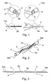
- Fig. 1 presents one hoisting rope 1aa of the new hoisting roping 1a as well as one hoisting rope 1bb of the old hoisting roping 1b opened up at their ends.
- the hoisting ropes 1aa and 1bb are opened up at their ends for essentially the same length as each other, said length being a suitable distance for the purpose and every second strand of each rope is removed for this distance.
- the core of the new hoisting rope 1bb is also removed for this distance.
- the hoisting ropes according to the example each have three remaining strands 2a, 2b, and the old rope 1bb also has the core 3 of the rope remaining.
- sleeves 4, 4a are threaded onto the rope, the diameter of said sleeves being only slightly greater than the outer diameter of the ropes, in which case the sleeves 4, 4a only just fit onto the ropes.
- Fig. 2 presents a new hoisting rope 1aa and an old hoisting rope 1bb in a situation in which the ends of the hoisting ropes have started to be spliced together.
- the strands 2a of the new hoisting rope 1aa have started to be threaded together with the strands 2b of the old rope around the core 3 of the new rope 1aa.
- the sleeves 4 and 4a are still so far away from each other that the cutting points 5 of the removed strands are visible on the side of the future joint 5a with respect to the sleeves 4 and 4a.
- the joint location is strengthened by means of the sleeves 4, 4a, e.g. according to what is presented in Fig. 3 .
- one sleeve 4, as well as one sleeve 4a positioned essentially in the centre of the extension point 5a in order to strengthen the joint are placed onto the cutting point 5 of the strands on both the new and the old rope.
- All the sleeves 4, 4a are compressed tightly onto the rope with a suitable tool.
- At least the inner edges of the sleeves are beveled. The sleeves keep the cut and spliced strands inside them reliably.
- the finished joint is suitably flexible and very strong, and the thin sleeves do not become entangled in the jump guards of the rope pulleys. If necessary there can be more joint-strengthening sleeves 4a at the centre of the joint 5a between the sleeves 4, e.g. there can be altogether two or three sleeves 4a.
- Figs. 4-10 present different methods and arrangements for replacing the old hoisting roping 1b of an elevator after the joint described above has been made.
- Figs. 4-10 present only the complete hoisting ropings 1a and 1b, not their separate hoisting ropes 1aa and 1bb installed parallel to each other.
- the hoisting roping 1a contains a plurality of hoisting ropes 1aa that are essentially similar to each other and positioned side by side and correspondingly the hoisting roping 1b contains a plurality of hoisting ropes 1bb that are essentially similar to each other and positioned side by side.
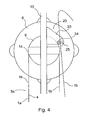
- Fig. 4 presents a simplified and magnified side view of a traction appliance 20 for a hoisting rope used in the method according to the invention.
- the traction appliance 20 contains a frame 23, to which is fixed a friction wheel 24 and a rope lifting wheel 25.
- the friction wheel 24 is provided with a friction surface that enables good friction grip, such as with a rubber lining or plastic lining or e.g. with a polyurethane lining, with a combination of the aforementioned or with some other suitable and flexible lining.
- the friction wheel can also be made so that instead of a flexible material the friction wheel 24 is spring-mounted by means of a separate spring or similar.
- the rim of the lifting wheel 25 is provided with a V-groove, serration or other suitable surface.
- the friction wheel 24 and the lifting wheel 25 are fitted to the frame 23 with bearings allowing rotation and positioned in relation to each other such that the lifting wheel 25 can be tightened with a tightening element suited to the purpose against the friction wheel 24.
- the tightening allows so much adjustment tolerance that hoisting ropes of essentially all diameters can be installed and tightly compressed between the wheels 24 and 25.
- the traction appliance 20 is provided with fixing means, which are fitted such that the traction appliance 20 can be fixed either to the guide rail 10 of the elevator car 7, to the structures of the hoisting machine 8 or to another suitable point, and the dimensions of the traction appliance 20 and the situations of the wheels 24, 25 are selected so that after fixing, the outer rim of the friction wheel 24 presses against the traction sheave 9.
- the friction wheel 24 can press against the outer rim of the traction sheave 9 and/or against the rope in the grooves of the traction sheave or also against the side or the inner rim of the traction sheave.
- the method and the appliance arrangement can be utilized beneficially so that the hoisting roping (1b, 1a) moves between the traction sheave (9) and the friction wheel (24) to a first direction, and between the friction wheel (24) and the lifting wheel (25) to a second direction.
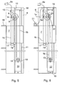
- Fig. 5 presents a simplified side view of a traction sheave elevator equipped with hoisting roping 1b comprised of parallel hoisting ropes 1bb and with a counterweight 12, in which the hoisting roping replacement method according to the invention can be used.
- the elevator car 7 is suspended on the hoisting roping 1b and it moves backwards and forwards in the elevator shaft 6 along guide rails 10 in an essentially vertical direction.
- the elevator receives its lifting power from a hoisting machine 8 provided with a traction sheave 9, which is connected at least to an elevator control system 8a.
- the first end of the hoisting roping 1b is fixed to the fixing element 15 disposed in the upper part of the elevator shaft 6, from where the hoisting roping is led to pass first under the elevator car 7 around the diverting pulleys 17 to the traction sheave 9 of the hoisting machine 8 in the upper part of the elevator shaft, from where the hoisting roping 1b is further led to travel to the diverting pulley 13 of the counterweight 12, and after passing around the diverting pulley 13 the roping is led to the fixing point 16 disposed in the upper part of the elevator shaft, to which the second end of the hoisting roping is fixed.
- Both the traction sheave 9 and the diverting pulley 13 of the counterweight 12 are provided with jump guards 14, which can also if necessary be disposed on other rope pulleys.
- the elevator shaft 6 in Fig. 5 is truncated in such a way that of the floor levels only the bottommost, the next to topmost and the topmost floor 18 are visible.
- the rope suspension can, of course, also be different to that described.
- Fig. 6 presents an elevator according to Fig. 6 , in which the old hoisting roping 1b is currently being replaced with new hoisting roping 1a.
- the elevator car 7 is driven at first to a suitable location in the shaft with regard to the replacement, which in the elevator according to the example is in the upper part of the elevator shaft.
- the elevator car 7 is driven so that the roof of the car is essentially at the level of the topmost floor 18 and locked into position e.g. by means of the safety gear 7a of the elevator.
- the car staying in position is ensured with a safety chain or with other suitable means.
- the counterweight 12 is in this case in the lower part of the elevator shaft, where it is supported e.g.
- the hoisting ropes 1aa of the new hoisting roping 1a that is still on reels 21 are taken to the topmost floor 18.
- the reels 21 can be placed also elsewhere than on the topmost floor 18, e.g. on the bottommost floor, in which case the counterweight 12 is supported e.g. at the top end of the shaft.
- the traction appliance 20 that is described in more detail in connection with Fig. 4 is fixed either to the guide rail 10 of the elevator car 7, to the structures of the hoisting machine 8 or to another suitable point such that after the fixing the friction wheel 24 presses against the traction sheave 9.
- the hoisting ropes on the side of the counterweight 12 are supported temporarily by fastening them to a suitable support point 22 e.g. on the top part of the elevator car 7.
- the hoisting ropes 1aa of the new hoisting roping 1a are threaded through the rope bars in the fixing points 15 and the new ropes 1aa are joined to the detached ends of the old ropes 1bb in the manner presented in Figs. 1-3 .
- the ropes can be guided into the shaft also with other suitable methods. Additionally special guide pipes are placed if necessary between the reels 21 and the rope bars, so that the new ropes do not become entangled with each other, become damaged or damage the structures of the building, such as doors and door frames, etc, as they leave the reels.
- the guide pipes prevent the ropes from rubbing against sharp edges and prevent the ropes from making places dirty.
- the guide pipes are not shown in the figures.
- the safety circuit of the door of the topmost floor is bypassed with the stop button, in which case the hoisting machine 8 of the elevator can be driven while the doors of the topmost floor are open.
- the hoisting machine 8 is started in service drive and the new hoisting roping 1a is driven into position with service drive by pulling the new roping into position by means of the old hoisting roping 1b, which old hoisting roping 1b is guided to pass between the friction wheel 24 of the traction appliance 20 and the lifting wheel 25.
- the old rope 1b is at the same time guided into the elevator shaft or if desired onto a rope reel.
- the driving of the ropes is stopped when the rope is driven so far that the ends of the new hoisting ropes 1aa come out of through the throat between the friction wheel and the lifting wheel of the traction appliance 20 so far that the ends can be fastened to their fixing points 16.
- the final ends of the old hoisting ropes 1bb are fastened e.g. to the previous temporary support point 22 for the ropes and the new ropes are cut between the joint location 5a and the traction appliance 20 such that the joint location remains on the side of the old ropes 1bb and such that the new ropes 1aa extend to their fixing points 16.
- the ends of the old ropes 1bb are carefully guided down and the new ropes 1aa are fastened e.g. to the previous temporary support point 22 for the ropes, after which the tightening between the friction wheel 24 and the lifting wheel 25 of the traction appliance 20 is loosened and the ends of the new ropes 1aa are fastened to their fixing points 16.
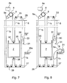
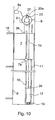
- Fig. 7 presents a traction sheave elevator suspended in a different way to that presented above, in which the hoisting roping replacement method according to the invention can also be used.
- the figure presents a simplified side view of a traction sheave elevator without counterweight provided with hoisting roping 1b comprising parallel hoisting ropes 1bb.
- the elevator car 7 is suspended on the hoisting roping 1b and it moves backwards and forwards in the elevator shaft 6 along guide rails in an essentially vertical direction.
- the elevator receives its lifting power from a hoisting machine 8 provided with a traction sheave 9, which is connected at least to an elevator control system 8a.
- the first end of the hoisting roping 1b is fixed to the first fixing point 31 of the rope compensation appliance situated on the top part of the elevator car 7, from where the hoisting roping is led to run first upwards to the diverting pulley 30 of the rope compensation appliance and after passing over the top of it to the first diverting pulleys 27 in the lower part of the shaft 6, and after passing around the bottom of which the hoisting roping 1b is led to the diverting pulley 28 situated below the elevator car 7.
- the hoisting roping 1b After passing around the top of the diverting pulley 28 the hoisting roping 1b is further led to the second diverting pulleys 29 in the lower part of the elevator shaft 6, and after passing around the bottom of which the hoisting roping 1b is led to the traction sheave 9 of the hoisting machine 8 in the machine room 26 situated above the elevator shaft 6 via the diverting pulley 9a. From the traction sheave 9 the roping is led onwards to the diverting pulley 9a and after passing around the bottom of this the roping is once again led to the traction sheave 9.
- Figs. 8 and 9 present an elevator according to Fig. 7 , in which the old hoisting roping 1b is currently being replaced with new hoisting roping 1a.
- the elevator car 7 is driven at first to a suitable location in the shaft with regard to the replacement, which in the elevator according to the example is in the lower part of the elevator shaft.
- the elevator car 7 is driven so that the roof of the car is essentially at a level midway between the next to bottommost and the bottommost floor 18a and locked into position e.g. by means of the safety gear of the elevator.
- the car staying in position is ensured with a safety chains 35 or with other suitable means, which safety chains 35 are fixed to a sufficiently strong structure in the elevator shaft.
- the hoisting ropes 1aa of the new hoisting roping 1a that is still on reels 21 are situated on the bottommost floor 18a.
- the driving of the ropes is stopped when the rope is driven so far that the starting ends of the new hoisting ropes 1aa come past all the rope pulleys so far that the starting ends can be fastened to their fixing points 34.
- the new ropes 1aa are cut so that the joint location 5a remains on the side of the old ropes 1bb and so that the new ropes 1aa extend to their fixing points 34.
- the ends of the old ropes 1bb are carefully guided onto the rope reels 36 and the ends of the new ropes 1aa are fastened to their fixing points 34.
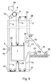
- Fig. 10 presents a simplified side view of another traction sheave elevator provided with hoisting roping 1b comprising parallel hoisting ropes 1bb and with a counterweight 12, in which the hoisting roping replacement method according to the invention can be used.
- the elevator car 7 is suspended on the hoisting roping 1b with a suspension ratio 1:1 and it moves backwards and forwards in the elevator shaft 6 along guide rails 10 in an essentially vertical direction.
- the elevator receives its lifting power from a hoisting machine 8 provided with a traction sheave 9, which is connected at least to an elevator control system 8a.
- the first end of the hoisting roping 1b is fixed to the fixing element 38 on the top part of the elevator car 7, from where the hoisting roping is led to run to the traction sheave 9 of the hoisting machine 8 in the upper part of the elevator shaft or in the machine room, and after passing around the traction sheave 9 the hoisting roping 1b is further led to the fixing point 39 situated on the counterweight 12 that moves along guide rails 11 in an essentially vertical direction, to which the second end of the hoisting roping is fastened.
- the elevator shaft 6 in Fig. 10 is truncated in such a way that of the floor levels only the bottommost, the next to topmost and the topmost floor 18 are visible.
- a simpler traction appliance 20a is used than the traction appliance 20 described earlier.
- This solution contains only one friction wheel 37, essentially similar in construction to the friction wheel 24, which is fitted to press against the outer surface of the traction sheave 9 such that the hoisting ropes 1bb of the old hoisting roping 1b and the hoisting ropes 1aa of the new hoisting roping 1a press without slipping against the traction sheave 9 in connection with replacement of the roping.
- the friction wheel 37 is pressed strongly against the traction sheave 9 such that the hoisting ropes remain compressed between the friction wheel 37 and the traction sheave 9.
- the compression force of the friction wheel 37 is dimensioned so that the hoisting ropes do not slip on the traction sheave although the ends of the hoisting ropes are detached from their fixing points 38 and 39.
- the hoisting ropes 1aa of the new hoisting roping 1a that is still on reels 21 are taken to the topmost floor 18.
- the reels 21 and the actual performance of the replacement are not shown in Fig. 10 . Instead the reels 21 are presented in a corresponding position in Fig. 6 .
- the hoisting ropes are driven, either all at the same time or one at a time, with the hoisting machine 8 of the elevator such that the hoisting ropes 1bb of the old hoisting roping 1b pull the new hoisting ropes 1aa of the new hoisting roping 1a into position in the place of the old at the same time as the old hoisting ropes are guided either onto reels or into a suitable collection place.
- the new hoisting ropes are pulled into their position the extension is detached, the new hoisting ropes are cut to their right lengths and the ends of the new hoisting ropes are fastened to their fixing points 38 and 39.
- the contact area between the friction wheel 24, 37 and the traction sheave 9 is preferably located aside from the zenith of the traction sheave 9. This way the need for deviating horizontally the roping 1b to be fed between the friction wheel 24 and the lifting wheel 25 is diminished. This way also the traction between the roping 1a, 1b and the traction sheave 9 can be increased on a chosen side of the contact area between traction sheave 9 and the friction wheel 24.
- the elevator car can be locked into its position during replacement of the hoisting ropes in some other way than by lowering it to rest on the safety gear.
- the locking can in this case also be, for instance, by means of a guide rail brake or an arresting stop.
- the elevator car suspension presented can be different to what is described above.
- the positioning and number of the diverting pulleys can vary and the compensation appliance can also be in the upper part of the elevator shaft, in which case certain details of the rope replacement are different than those explained in the examples above.
- the core of the ropes used can be any suitable material whatever, such as steel, textile, Kevlar, Teflon, etc.
- the friction surface of the friction wheel can be any material whatsoever that is suitable and essentially soft and that possesses essentially great friction, such as e.g. rubber, plastic or urethane and correspondingly there can be serration or some other suitable friction surface on the rim of the lifting wheel instead of V-grooves.
Landscapes
- Lift-Guide Devices, And Elevator Ropes And Cables (AREA)
Description
- The present invention relates to a method for replacing the hoisting roping of an elevator as disclosed in the preamble of claim 1 and a traction appliance arrangement used in the replacement as disclosed in the preamble of
claim 10. - The hoisting ropes used in elevators wear in use and can even break when they are worn. For this reason the safety regulations for elevators require that the hoisting ropes in elevators with hoisting ropes must be replaced with new ones at certain intervals. According to prior art the hoisting ropes are generally replaced by first removing the old hoisting ropes and after that installing the new hoisting ropes. A drawback of this solution is that replacement of the ropes with this method is awkward and takes a lot of time. Especially in elevators without counterweight, in which the suspension ratio is great, e.g. between 4:1-12:1, replacing the ropes with this conventional method is very awkward and slow owing to the numerous diverting pulleys and large rope lengths, nor is it always necessarily safe.
- Prior art also includes solutions in which the new ropes are drawn into position by means of the old hoisting ropes. In this case the ends of the old hoisting ropes are detached and the new ropes are attached to the second free ends and then the new ropes are guided into place by pulling on the old ropes. One problem is making a joint between the old and the new hoisting ropes that is durable and suitably thin. Joints that are sufficiently strong can easily become so thick that they do not bend well around the rope pulleys and in addition they are easily entangled on the rope jump guards. A further problem is that this method is only suitable for thin and relatively short ropes, which are so light that they can be pulled into position by human muscle power. This method is not suited to thick and long ropes.
- One prior art method in this context is pulling with a cable stocking that is intended for pulling cables. One problem with this, however, is the aforementioned thick joint between the ropes, in which case the joints easily entangle with the rope pump guards connected to the rope pulleys and the ropes fall into the shaft, causing hazards and at least becoming themselves damaged. Another problem is the uncertain durability of the joint, which has also caused falling of the ropes.
- Joints are also made with wire, by splicing and securing with tape as well as by bundling some of the strands of the rope ends between the ends of the ropes. When bundling, some of the strands in the ends of the ropes are left longer and these strands are tightly bent at about halfway along the strands and then interlaced at the points of the bend. The joint is further secured with taping and greased. A problem in all the jointing methods mentioned, however, is that they are essentially laborious and uncertain or they are not at all suited to large lifting heights.
- Another prior-art method for making a joint in ropes is placing an essentially large, compressive sleeve around the ends of the ropes so that the intact ends of the new and old rope are positioned inside the sleeve and the sleeve is tightly, compressed around the ends of the rope. The joint is suitable for pulling ropes by hand, but it is not sufficiently strong for pulling mechanically. Likewise, owing to the large sleeve, the extension requires a large bending radius and looser jump guards on the rope pulleys, thus this method is not suited to solutions in which the diverting pulleys are small.
TheJP 9086823 A independent claims 1 and 9.
TheJP 2066092 A
TheJP 5044785 A JP 4327483 A
TheJP 2003089486 A - The purpose of this invention is to eliminate aforementioned drawbacks and to achieve an easy, quick and safe method for replacing the hoisting ropes of an elevator. Another purpose is to achieve a method that is suitable for use in many different types of suspension and for replacing the hoisting ropes of many different-sized elevators. In this case the purpose is aloo that the method is suited for replacing the hoisting ropes of e.g., both elevators with machine room and elevators without machine room, and likewise for replacing the hoisting ropes of elevators with counterweight and elevators without counterweight. The purpose of the invention is also to achieve a simple and operationally reliable traction appliance arrangement to use in the replacement of hoisting ropes, which receives its operating power from the elevator's own hoisting machine via the traction sheave of the elevator - The method of the invention is characterized by what is disclosed in the characterization part of claim 1 and the traction appliance arrangement of the invention is characterized by what is disclosed in the characterization part of
claim 10. Other embodiments of the invention are characterized by what is disclosed in the other claims. - Some inventive embodiments are also discussed in the descriptive section of the present application. The inventive content may also consist of several separate inventions, especially if the invention is considered in the light of expressions or implicit sub-tasks or from the point of view of advantages or categories of advantages achieved. In this case, some of the attributes contained in the claims below may be superfluous from the point of view of separate inventive concepts. Correspondingly, each of the different details presented in connection with the embodiment of the invention can also be used in other embodiments.
- The method according to the invention is characterized by claim 1 and the arrangement of the invention is characterized by
claim 9. Avantageous embodiment of the invention are subject matter of the dependent claims. According to the invention both the ropes of the new hoisting roping and the ropes of the old hoisting roping are joined together, after which the new hoisting roping is pulled into position by means of the old hoisting roping and a friction wheel which is arranged to press against the traction sheave and rotated by the traction sheave. Thus, the hoisting machine of the elevator can be utilized. - Further the old roping is guided to pass between the friction wheel and a lifting wheel arranged to be fitted against the friction wheel.
- The method according to a preferred embodiment of the invention is characterized in that the ropes of the new roping and the ropes of the old roping are joined to each other by splicing the ropes together at one of their ends and by strengthening the joint by means of compressive sleeves.
- The method according to a preferred embodiment of the invention is characterized in that the ropes of the roping to be replaced are hoisting ropes and in that one of the ends of each of the new and old hoisting ropes is provided with one or more compressive sleeves, the ends are opened up for a suitable length, every second strand from the opened ends is removed and the core of one of the hoisting ropes is out off, and the ends of the opened hoisting ropes are spliced together with the remaining strands around the core of the other hoisting rope, and in that the joint location is reinforced at least at the point of the ends of the cut strands with compressive sleeves.
- The method according to a yet another preferred embodiment of the invention is characterized in that the joint location is additionally reinforced with one or more compressive sleeves between the ends of the cut strands.
- The method according to a yet another preferred embodiment of the invention is characterized in that at least the following procedures are performed in connection with replacement of the hoisting roping: the elevator car is locked into position in the elevator shaft; the ends that extend the hoisting ropes of the old hoisting roping are detached from their first fixing points; the hoisting ropes of the new hoisting roping and the hoisting ropes of the old hoisting roping are joined together at one of their ends and the joint location is secured by means of compressive sleeves on top of the ropes; the hoisting ropes of the old hoisting roping are detached from their second fixing point; and the hoisting ropes of the old hoisting roping are pulled out of their position by means of the hoisting machine of the elevator using service drive while at the same time feeding the hoisting ropes of the new hoisting roping into the place of the old hoisting ropes.
- The method according to a yet another preferred embodiment of the invention is characterized in that in connection with replacement of the hoisting roping in an elevator equipped with a counterweight at least the following procedures are performed: the elevator car and the counterweight are locked into position in the elevator shaft; the traction appliance for the ropes is fastened in such a way that the friction wheel in the traction appliance rests against the traction sheave of the hoisting machine; the ends of the hoisting ropes of the old hoisting roping on the counterweight side are detached from their fixing points; the ends of the hoisting ropes of the old hoisting roping on the counterweight side are fitted and tightened between the friction wheel and the lifting wheel in the traction appliance; the ends of the old hoisting ropes on the elevator car side are detached from their fixing points; the hoisting ropes of the new hoisting roping and the hoisting ropes of the old hoisting roping are joined together at one of their ends and the joint location is secured by means of compressive sleeves on top of the ropes; and the hoisting ropes of the old hoisting roping are pulled out of their position by means of the hoisting machine of the elevator and the traction appliance using service drive while at the same time feeding the hoisting ropes of the new hoisting roping into the place of the old hoisting ropes.
- The method according to a yet another preferred embodiment of the invention is characterized in that in connection with replacement of the hoisting roping in an elevator equipped with a counterweight at least the following procedures are performed: the elevator car and the counterweight are locked into position in the elevator shaft; the traction appliance for the ropes is fastened in such a way that the friction wheel in the traction appliance presses against the traction sheave of the hoisting machine; the ends of the hoisting ropes of the old hoisting roping on the counterweight side are detached from their fixing points; the ends of the old hoisting ropes on the elevator car side are detached from their fixing points; the hoisting ropes of the new hoisting roping and the hoisting ropes of the old hoisting roping are joined together at one of their ends and the joint location is secured by means of compressive sleeves on top of the ropes; and the hoisting ropes of the old hoisting roping are pulled out of their position by means of the hoisting machine of the elevator and the friction wheel of the traction appliance using service drive while at the same time feeding the hoisting ropes of the new hoisting roping into the place of the old hoisting ropes.
- The method according to a yet another preferred embodiment of the invention is characterized in that in connection with replacement of the hoisting roping in an elevator without counterweight at least the following procedures are performed: the elevator car is locked into position in the elevator shaft; the ends that extend the hoisting ropes of the old hoisting roping are detached from their first fixing points; the hoisting ropes of the new hoisting roping and the hoisting ropes of the old hoisting roping are joined together at one of their ends and the joint location is secured by means of compressive sleeves on top of the ropes; the hoisting ropes of the old hoisting roping are detached from their second fixing point; and the hoisting ropes of the old hoisting roping are pulled out of their position by means of the hoisting machine of the elevator using service drive while at the same time feeding the hoisting ropes of the new hoisting roping into the place of the old hoisting ropes.
- Likewise the traction appliance arrangement according to the invention is characterized in that the arrangement comprises at least a traction appliance fixed into position in the elevator shaft, which appliance contains a frame, onto which frame a friction wheel provided with a suitable friction surface is fitted with bearings allowing rotation, which friction wheel is arranged to press against the traction sheave.
- The lifting wheel provided with a suitable friction surface is fitted to the frame with bearings allowing rotation, in addition to the friction wheel, and the elevator hoisting rope to be replaced is arranged for placement between the friction surfaces of the friction wheel and the lifting wheel. At least one of the wheels is fitted to be tightened against the other wheel when the elevator rope is placed between the friction surfaces of the wheels.
- The traction appliance arrangement according to a preferred embodiment of the invention is characterized in that the friction surface of the friction wheel is rubber, plastic, urethane or other suitable flexible material having essentially large friction.
- The traction appliance arrangement according to yet another preferred embodiment of the invention is characterized in that the rim of the lifting wheel is provided with grooving, serration or other suitable surface having essentially large friction.
- The traction appliance arrangement according to yet another preferred embodiment of the invention is characterized in that the dimensions of the traction appliance and the situations of the friction and the lifting wheels are selected so that when the traction appliance is fixed into position, the outer rim of the friction wheel rests against the traction sheave of the hoisting machine.
- One advantage of the method and traction appliance arrangement is, among others, that even in a complex rope suspension the hoisting roping can be easily, ergonomically, efficiently and safely replaced. Another advantage is that the old and the new hoisting ropes can be joined to each other almost seamlessly with an essentially flexible joint without essentially increasing the diameter of the joint location, in which case the new ropes can be pulled into position in a single operation using the old hoisting ropes as an aid, even though the jump guards on the rope pulleys are very close to the ropes. A further advantage is that the joint location of the ropes is in terms of tensile strength sufficiently reliable and strong for mechanical replacement, so that the method can also be used for replacing essentially thick and strong ropes, which ropes would be too heavy to be pulled by hand. In this case the method can be used e.g. in so-called high-rise elevators. Another advantage is that the joint is safe and certain, because an incorrectly spliced extension cannot be used by accident since the sleeves are essentially precisely dimensioned and cannot be installed onto an incorrectly spliced extension. The flexible joint location also travels well in the grooves of the rope pulleys when performing the replacement. An additional advantage is that all the ropes of the elevator can be replaced simultaneously, in which case the replacement is fast and superfluous friction forces are avoided. As a result of the fast replacement, the elevator is out of service for a shorter time and the costs of the replacement remain small. Another advantage is that the joint is very tough, and does not in any case break unexpectedly. Yet another advantage is that the solution according to the invention enables replacement of the ropes without disassembling the elevator equipment, nor is a separate electric hoist needed in the replacement and the need for other necessary tools is minimal. The solution according to the invention is very versatile and is suited to many different suspension solutions, and an extremely good solution for steel wire ropes of which the diameter is 4 mm or greater. In the following, the invention will be described in more detail by the aid of one of its embodiments with reference to the attached drawings, wherein
- Fig. 1
- presents both a new and an old hoisting rope disassembled at their ends,
- Fig. 2
- presents the splicing together of a new and an old hoisting rope,
- Fig. 3
- presents both a new and an old hoisting rope joined together,
- Fig. 4
- presents a magnified side-view of a traction appliance used in the elevator solution according to
Figs. 5 and 6 , - Fig. 5
- presents a simplified side-view of a traction sheave elevator with counterweight, in which the method according to the invention can be used,
- Fig. 6
- presents an elevator according to
Fig. 5 , in which the hoisting ropes are currently being replaced, - Fig. 7
- presents a simplified side-view of a traction sheave elevator without counterweight, in which the method according to the invention can be used,
- Fig. 8
- presents an elevator according to
Fig. 7 , in which the hoisting ropes have just begun to be replaced and - Fig. 9
- presents an elevator according to
Fig. 7 , in which replacement of the hoisting ropes has progressed further thanFig. 8 and - Fig. 10
- presents a simplified side-view of another traction sheave elevator with counterweight, in which the method according to the invention can be used.
-
Fig. 1 presents one hoisting rope 1aa of thenew hoisting roping 1a as well as one hoisting rope 1bb of theold hoisting roping 1b opened up at their ends. The hoisting ropes 1aa and 1bb are opened up at their ends for essentially the same length as each other, said length being a suitable distance for the purpose and every second strand of each rope is removed for this distance. The core of the new hoisting rope 1bb is also removed for this distance. In this case the hoisting ropes according to the example each have three remainingstrands core 3 of the rope remaining. Before the strands are opened up and cut off a suitable number of thin and essentiallyshort sleeves sleeves sleeves sleeves sleeves 4 are threaded onto the end of the new rope 1aa and onesleeve 4a is threaded onto the end of the old rope 1bb. -
Fig. 2 presents a new hoisting rope 1aa and an old hoisting rope 1bb in a situation in which the ends of the hoisting ropes have started to be spliced together. Thestrands 2a of the new hoisting rope 1aa have started to be threaded together with thestrands 2b of the old rope around thecore 3 of the new rope 1aa. Thesleeves sleeves - When the
strands sleeves Fig. 3 . In this case onesleeve 4, as well as onesleeve 4a positioned essentially in the centre of theextension point 5a in order to strengthen the joint, are placed onto thecutting point 5 of the strands on both the new and the old rope. All thesleeves sleeves 4a at the centre of the joint 5a between thesleeves 4, e.g. there can be altogether two or threesleeves 4a. -
Figs. 4-10 present different methods and arrangements for replacing theold hoisting roping 1b of an elevator after the joint described above has been made. For the sake of clarityFigs. 4-10 present only thecomplete hoisting ropings roping 1a contains a plurality of hoisting ropes 1aa that are essentially similar to each other and positioned side by side and correspondingly the hoistingroping 1b contains a plurality of hoisting ropes 1bb that are essentially similar to each other and positioned side by side. -
Fig. 4 presents a simplified and magnified side view of atraction appliance 20 for a hoisting rope used in the method according to the invention. Thetraction appliance 20 contains aframe 23, to which is fixed afriction wheel 24 and arope lifting wheel 25. Thefriction wheel 24 is provided with a friction surface that enables good friction grip, such as with a rubber lining or plastic lining or e.g. with a polyurethane lining, with a combination of the aforementioned or with some other suitable and flexible lining. The friction wheel can also be made so that instead of a flexible material thefriction wheel 24 is spring-mounted by means of a separate spring or similar. Likewise the rim of thelifting wheel 25 is provided with a V-groove, serration or other suitable surface. Thefriction wheel 24 and thelifting wheel 25 are fitted to theframe 23 with bearings allowing rotation and positioned in relation to each other such that thelifting wheel 25 can be tightened with a tightening element suited to the purpose against thefriction wheel 24. The tightening allows so much adjustment tolerance that hoisting ropes of essentially all diameters can be installed and tightly compressed between thewheels traction appliance 20 is provided with fixing means, which are fitted such that thetraction appliance 20 can be fixed either to theguide rail 10 of theelevator car 7, to the structures of the hoistingmachine 8 or to another suitable point, and the dimensions of thetraction appliance 20 and the situations of thewheels friction wheel 24 presses against thetraction sheave 9. Depending on the construction and the fixing, thefriction wheel 24 can press against the outer rim of thetraction sheave 9 and/or against the rope in the grooves of the traction sheave or also against the side or the inner rim of the traction sheave. - The method and the appliance arrangement can be utilized beneficially so that the hoisting roping (1b, 1a) moves between the traction sheave (9) and the friction wheel (24) to a first direction, and between the friction wheel (24) and the lifting wheel (25) to a second direction.
-
Fig. 5 presents a simplified side view of a traction sheave elevator equipped with hoistingroping 1b comprised of parallel hoisting ropes 1bb and with acounterweight 12, in which the hoisting roping replacement method according to the invention can be used. Theelevator car 7 is suspended on the hoistingroping 1b and it moves backwards and forwards in theelevator shaft 6 alongguide rails 10 in an essentially vertical direction. The elevator receives its lifting power from a hoistingmachine 8 provided with atraction sheave 9, which is connected at least to anelevator control system 8a. The first end of the hoistingroping 1b is fixed to the fixingelement 15 disposed in the upper part of theelevator shaft 6, from where the hoisting roping is led to pass first under theelevator car 7 around the divertingpulleys 17 to thetraction sheave 9 of the hoistingmachine 8 in the upper part of the elevator shaft, from where the hoistingroping 1b is further led to travel to the divertingpulley 13 of thecounterweight 12, and after passing around the divertingpulley 13 the roping is led to thefixing point 16 disposed in the upper part of the elevator shaft, to which the second end of the hoisting roping is fixed. Both thetraction sheave 9 and the divertingpulley 13 of thecounterweight 12 are provided withjump guards 14, which can also if necessary be disposed on other rope pulleys. Theelevator shaft 6 inFig. 5 is truncated in such a way that of the floor levels only the bottommost, the next to topmost and thetopmost floor 18 are visible. The rope suspension can, of course, also be different to that described. -
Fig. 6 presents an elevator according toFig. 6 , in which theold hoisting roping 1b is currently being replaced withnew hoisting roping 1a. With the rope replacement method according to the invention theelevator car 7 is driven at first to a suitable location in the shaft with regard to the replacement, which in the elevator according to the example is in the upper part of the elevator shaft. Theelevator car 7 is driven so that the roof of the car is essentially at the level of thetopmost floor 18 and locked into position e.g. by means of thesafety gear 7a of the elevator. In addition the car staying in position is ensured with a safety chain or with other suitable means. Correspondingly thecounterweight 12 is in this case in the lower part of the elevator shaft, where it is supported e.g. on the floor of theshaft 6 by means ofsupport elements 19. Before starting the replacement the hoisting ropes 1aa of thenew hoisting roping 1a that is still onreels 21 are taken to thetopmost floor 18. Depending on the suspension solution of the elevator thereels 21 can be placed also elsewhere than on thetopmost floor 18, e.g. on the bottommost floor, in which case thecounterweight 12 is supported e.g. at the top end of the shaft. - After this the
traction appliance 20 that is described in more detail in connection withFig. 4 is fixed either to theguide rail 10 of theelevator car 7, to the structures of the hoistingmachine 8 or to another suitable point such that after the fixing thefriction wheel 24 presses against thetraction sheave 9. Next the hoisting ropes on the side of thecounterweight 12 are supported temporarily by fastening them to asuitable support point 22 e.g. on the top part of theelevator car 7. After the supporting the ends of the ropes on the side of thecounterweight 12 are detached from their fixingpoint 16 and the freed ends of the ropes are guided to pass between thefriction wheel 24 of thetraction appliance 20 and thelifting wheel 25, after which thelifting wheel 25 is firmly tightened against thefriction wheel 24, so that the ropes are compressed sufficiently strongly between the lifting wheel and the friction wheel. After this the temporary support of the hoisting ropes is removed by detaching the ropes from thesupport point 22. - Next the ends of the hoisting ropes on the side of the elevator car are detached from their fixing points 15, the hoisting ropes 1aa of the
new hoisting roping 1a are threaded through the rope bars in the fixing points 15 and the new ropes 1aa are joined to the detached ends of the old ropes 1bb in the manner presented inFigs. 1-3 . The ropes can be guided into the shaft also with other suitable methods. Additionally special guide pipes are placed if necessary between thereels 21 and the rope bars, so that the new ropes do not become entangled with each other, become damaged or damage the structures of the building, such as doors and door frames, etc, as they leave the reels. In addition the guide pipes prevent the ropes from rubbing against sharp edges and prevent the ropes from making places dirty. The guide pipes are not shown in the figures. Also, before pulling the new ropes into position the safety circuit of the door of the topmost floor is bypassed with the stop button, in which case the hoistingmachine 8 of the elevator can be driven while the doors of the topmost floor are open. After this the hoistingmachine 8 is started in service drive and thenew hoisting roping 1a is driven into position with service drive by pulling the new roping into position by means of theold hoisting roping 1b, whichold hoisting roping 1b is guided to pass between thefriction wheel 24 of thetraction appliance 20 and thelifting wheel 25. Theold rope 1b is at the same time guided into the elevator shaft or if desired onto a rope reel. - The driving of the ropes is stopped when the rope is driven so far that the ends of the new hoisting ropes 1aa come out of through the throat between the friction wheel and the lifting wheel of the
traction appliance 20 so far that the ends can be fastened to their fixing points 16. After this the final ends of the old hoisting ropes 1bb are fastened e.g. to the previoustemporary support point 22 for the ropes and the new ropes are cut between thejoint location 5a and thetraction appliance 20 such that the joint location remains on the side of the old ropes 1bb and such that the new ropes 1aa extend to their fixing points 16. Next the ends of the old ropes 1bb are carefully guided down and the new ropes 1aa are fastened e.g. to the previoustemporary support point 22 for the ropes, after which the tightening between thefriction wheel 24 and thelifting wheel 25 of thetraction appliance 20 is loosened and the ends of the new ropes 1aa are fastened to their fixing points 16. - When the first ends of the new ropes 1aa are fastened to their fixing points 16, the rope tightnesses are equalized by means of the hoisting machine such that no slack sections remain in the
roping 1a. Next the second ends of the new ropes 1aa are fastened to their fixing points 15 and the ropes are cut above the fixing points. After this theelevator car 7 and thecounterweight 12 are detached from their supports and driven the necessary equalization runs and if necessary the rope tightnesses are equalized. -
Fig. 7 presents a traction sheave elevator suspended in a different way to that presented above, in which the hoisting roping replacement method according to the invention can also be used. The figure presents a simplified side view of a traction sheave elevator without counterweight provided with hoistingroping 1b comprising parallel hoisting ropes 1bb. Theelevator car 7 is suspended on the hoistingroping 1b and it moves backwards and forwards in theelevator shaft 6 along guide rails in an essentially vertical direction. The elevator receives its lifting power from a hoistingmachine 8 provided with atraction sheave 9, which is connected at least to anelevator control system 8a. The first end of the hoistingroping 1b is fixed to thefirst fixing point 31 of the rope compensation appliance situated on the top part of theelevator car 7, from where the hoisting roping is led to run first upwards to the divertingpulley 30 of the rope compensation appliance and after passing over the top of it to the first divertingpulleys 27 in the lower part of theshaft 6, and after passing around the bottom of which the hoistingroping 1b is led to the divertingpulley 28 situated below theelevator car 7. After passing around the top of the divertingpulley 28 the hoistingroping 1b is further led to the second divertingpulleys 29 in the lower part of theelevator shaft 6, and after passing around the bottom of which the hoistingroping 1b is led to thetraction sheave 9 of the hoistingmachine 8 in themachine room 26 situated above theelevator shaft 6 via the divertingpulley 9a. From thetraction sheave 9 the roping is led onwards to the divertingpulley 9a and after passing around the bottom of this the roping is once again led to thetraction sheave 9. After passing around the top of the traction sheave a second time the roping is led downwards to the divertingpulley 32 on the roof of the elevator car, after passing around the bottom of which the hoisting roping is led to run upwards to the divertingpulleys 33 in themachine room 26, after passing around the top of which the roping is led to thefixing point 34 in the rope compensation appliance of the elevator car, to which the second end of the hoisting roping is fixed. In elevators without counterweight also the rope suspension can of course be different to what is described above. Theelevator shaft 6 inFigs 7-9 is truncated in such a way that of the floor levels only thebottommost floor 18a and the next to bottommost floor are visible. -
Figs. 8 and9 present an elevator according toFig. 7 , in which theold hoisting roping 1b is currently being replaced withnew hoisting roping 1a. With the rope replacement method according to the invention theelevator car 7 is driven at first to a suitable location in the shaft with regard to the replacement, which in the elevator according to the example is in the lower part of the elevator shaft. Theelevator car 7 is driven so that the roof of the car is essentially at a level midway between the next to bottommost and thebottommost floor 18a and locked into position e.g. by means of the safety gear of the elevator. In addition the car staying in position is ensured with asafety chains 35 or with other suitable means, whichsafety chains 35 are fixed to a sufficiently strong structure in the elevator shaft. Before starting the replacement the hoisting ropes 1aa of thenew hoisting roping 1a that is still onreels 21 are situated on thebottommost floor 18a. - After this the first ends of the hoisting ropes are detached from their fixing points 31 and the new ropes 1aa of the
new roping 1a are joined one at a time to the detached ends of the old ropes 1bb as described inFigs. 1-3 . Before pulling thenew ropes 1a into position voice contact is made between the person supervising in the machine room and the person supervising the rope reels. Voice contact is maintained essentially throughout the period of the replacement. Next the safety circuit of the door of the bottommost floor is bypassed by means of the stop button, in which case the hoistingmachine 8 can be driven while the door of the bottommost floor is open and in which case movement of the elevator car can if necessary be stopped also from below. After this the second ends of the old hoisting ropes 1bb are detached from their fixing points 34 and the hoistingmachine 8 is started in service drive and thenew hoisting roping 1a is driven into position with service drive by pulling thenew roping 1a into position by means of theold hoisting roping 1b, whichold hoisting roping 1b is at the same time guided onto therope reel 36 on thebottommost floor 18a or if desired into the elevator shaft. - The driving of the ropes is stopped when the rope is driven so far that the starting ends of the new hoisting ropes 1aa come past all the rope pulleys so far that the starting ends can be fastened to their fixing points 34. After this the new ropes 1aa are cut so that the
joint location 5a remains on the side of the old ropes 1bb and so that the new ropes 1aa extend to their fixing points 34. Next the ends of the old ropes 1bb are carefully guided onto therope reels 36 and the ends of the new ropes 1aa are fastened to their fixing points 34. - When the starting ends of the new ropes 1aa are fastened to their fixing points 34, the final ends of the new ropes are cut at a suitable point and the final ends of the new ropes 1aa are fastened to their fixing points 31. After this the
elevator car 7 is detached from being supported by the safety gear and is driven the necessary equalization runs by means of the hoistingmachine 8 to equalize the rope forces and the rope tightnesses are equalized if necessary by means of the hoisting machine such that no slack sections remain in theroping 1a. -
Fig. 10 presents a simplified side view of another traction sheave elevator provided with hoistingroping 1b comprising parallel hoisting ropes 1bb and with acounterweight 12, in which the hoisting roping replacement method according to the invention can be used. Theelevator car 7 is suspended on the hoistingroping 1b with a suspension ratio 1:1 and it moves backwards and forwards in theelevator shaft 6 alongguide rails 10 in an essentially vertical direction. The elevator receives its lifting power from a hoistingmachine 8 provided with atraction sheave 9, which is connected at least to anelevator control system 8a. The first end of the hoistingroping 1b is fixed to the fixingelement 38 on the top part of theelevator car 7, from where the hoisting roping is led to run to thetraction sheave 9 of the hoistingmachine 8 in the upper part of the elevator shaft or in the machine room, and after passing around thetraction sheave 9 the hoistingroping 1b is further led to thefixing point 39 situated on thecounterweight 12 that moves alongguide rails 11 in an essentially vertical direction, to which the second end of the hoisting roping is fastened. Theelevator shaft 6 inFig. 10 is truncated in such a way that of the floor levels only the bottommost, the next to topmost and thetopmost floor 18 are visible. - In the solution according to
Fig. 10 asimpler traction appliance 20a is used than thetraction appliance 20 described earlier. This solution contains only onefriction wheel 37, essentially similar in construction to thefriction wheel 24, which is fitted to press against the outer surface of thetraction sheave 9 such that the hoisting ropes 1bb of theold hoisting roping 1b and the hoisting ropes 1aa of thenew hoisting roping 1a press without slipping against thetraction sheave 9 in connection with replacement of the roping. - In the elevator arrangement according to
Fig. 10 replacement of the hoisting roping is performed e.g. in the way that theelevator car 7 is driven at first to a suitable location in the shaft with regard to the replacement, which in the elevator according to the example is in the upper part of theelevator shaft 6. Theelevator car 7 is locked into position e.g. by means of thesafety gear 7a of the elevator. In addition the car staying in position is ensured with a safety chain or with other suitable means. Correspondingly thecounterweight 12 is in this case in the lower part of the elevator shaft, where it is supported e.g. on the floor of theshaft 6 by means ofsupport elements 19. Additionally thefriction wheel 37 is pressed strongly against thetraction sheave 9 such that the hoisting ropes remain compressed between thefriction wheel 37 and thetraction sheave 9. The compression force of thefriction wheel 37 is dimensioned so that the hoisting ropes do not slip on the traction sheave although the ends of the hoisting ropes are detached from their fixing points 38 and 39. Before starting the replacement the hoisting ropes 1aa of thenew hoisting roping 1a that is still onreels 21 are taken to thetopmost floor 18. Thereels 21 and the actual performance of the replacement are not shown inFig. 10 . Instead thereels 21 are presented in a corresponding position inFig. 6 . - When it is verified in the manner described above that the hoisting ropes 1bb of the
old hoisting roping 1b do not slip, the second ends of the old hoisting ropes are detached from their fixing points 39 and the first ends of the old hoisting ropes from their fixing points 38 and a sleeved extension is made on the first end of the old hoisting ropes according to what was explained earlier. After making the extension the hoisting ropes are driven, either all at the same time or one at a time, with the hoistingmachine 8 of the elevator such that the hoisting ropes 1bb of theold hoisting roping 1b pull the new hoisting ropes 1aa of thenew hoisting roping 1a into position in the place of the old at the same time as the old hoisting ropes are guided either onto reels or into a suitable collection place. When the new hoisting ropes are pulled into their position the extension is detached, the new hoisting ropes are cut to their right lengths and the ends of the new hoisting ropes are fastened to their fixing points 38 and 39. - The contact area between the
friction wheel traction sheave 9 is preferably located aside from the zenith of thetraction sheave 9. This way the need for deviating horizontally theroping 1b to be fed between thefriction wheel 24 and thelifting wheel 25 is diminished. This way also the traction between theroping traction sheave 9 can be increased on a chosen side of the contact area betweentraction sheave 9 and thefriction wheel 24. - It is obvious to the person skilled in the art that the invention is not limited to the embodiments described above, in which the invention is described using examples, but that many adaptations and different embodiments of the invention are possible within the scope of the inventive concept defined by the claims presented below. Thus for example the elevator car can be locked into its position during replacement of the hoisting ropes in some other way than by lowering it to rest on the safety gear. The locking can in this case also be, for instance, by means of a guide rail brake or an arresting stop.
- It is further obvious to the person skilled in the art that the elevator car suspension presented can be different to what is described above. The positioning and number of the diverting pulleys can vary and the compensation appliance can also be in the upper part of the elevator shaft, in which case certain details of the rope replacement are different than those explained in the examples above.
- It is also obvious to the person skilled in the art that the sequence of the different phases of the method can differ to that presented. Thus for example detachment of the second ends of the hoisting ropes of the old hoisting roping can also be performed before connecting the ends of the old and the new hoisting ropes.
- It is also obvious to the person skilled in the art that the core of the ropes used can be any suitable material whatever, such as steel, textile, Kevlar, Teflon, etc.
- It is further obvious to the person skilled in the art that the construction of the equipment used in the replacement of the ropes of an elevator with counterweight can differ to what is presented above. Thus the friction surface of the friction wheel can be any material whatsoever that is suitable and essentially soft and that possesses essentially great friction, such as e.g. rubber, plastic or urethane and correspondingly there can be serration or some other suitable friction surface on the rim of the lifting wheel instead of V-grooves.
Claims (11)
- Method for replacing the roping of an elevator, which elevator comprises at least guide rails (10) along which an elevator car (7) provided with safety gear (7a) travels in the elevator shaft in an essentially vertical direction, a hoisting machine (8), a traction sheave (9) and roping (1b), whereby the ropes (1aa) of the new roping (1a) and the ropes (1bb) of the old roping (1b) are joined to each other at one of their ends, after which the new roping (1a) is pulled into position by means of the old roping (1b) and a friction wheel (24, 37), which friction wheel (24, 37) is arranged to press against the traction sheave (9) and rotated by the traction sheave (9), characterized in that the old roping (1b) is guided to pass between the friction wheel (24) and a lifting wheel (25) arranged to be fitted against the friction wheel (24).
- Method according to claim 1, characterized in that the ropes (1aa) of the new roping (1a) and the ropes (1bb) of the old roping (1b) are joined to each other by splicing the ropes (1aa and 1bb) together at one of their ends and by strengthening the joint by means of compressive sleeves (4, 4a) .
- Method according to claim 2, characterized in that the ropes of the roping (1a, 1b) to be replaced are hoisting ropes (1aa and ebb), and in that one of the ends of each of the new and old hoisting ropes (1aa and 1bb) is provided with one or more compressive sleeves (4), the ends are opened up for a suitable length, every second strand from the opened ends is removed and the core of one of the hoisting ropes (1aa or 1bb) is cut off, and the ends of the opened hoisting ropes (1aa and 1bb) are spliced together with the remaining strands (2a, 2b) around the core (3) of the other hoisting rope (1aa or 1bb), and in that the joint location (5a) is reinforced at least at the point of the ends (5) of the cut strands with compressive sleeves (4).
- Method according to claims 2 or 3, characterized in that the joint location (5a) is additionally reinforced with one or more compressive sleeves (4a) between the ends (5) of the cut strands.
- Method according to any of the preceding claims, characterized in that at least the following procedures are performed in connection with replacement of the hoisting roping:- the elevator car (7) is locked into position in the elevator shaft (6) - the ends that extend the hoisting ropes (1bb) of the old hoisting roping (1b) are detached from their first fixing points (15, 31, 38)- the hoisting ropes (1aa) of the new hoisting roping (1a) and the hoisting ropes (1bb) of the old huisting roping (1b) are joined together at one of their ends and the joint location (5a) is secured by means of compressive sleeves (4, 4a) on top of the ropes- the hoisting ropes (1bb) of the old hoisting roping (1b) are detached from their second fixing point (16, 34, 39) - the hoisting ropes (1bb) of the old hoisting roping (1b) are pulled out of their position by means of the hoisting machine (8) of the elevator using service drive while at the same tine feeding the hoisting ropes (1aa) of the new hoisting roping (1a) into the place of the old hoisting ropes (1bb).
- Method according to claim 2 or according to claim 2 and any of the preceding claims 3 to 5, in an elevator equipped with a counterweight (12), characterized in that in connection with replacement of the hoisting roping at least the following procedures are performed:- the elevator car (7) and the counterweight (12) are locked into position in the elevator shaft (6)- the traction appliance (20) for the ropes is fastened in such a way that the friction wheel (24) in the traction appliance rests against the traction sheave (9) of the hoisting machine (8)- the ends of the hoisting ropes (1bb) of the old hoisting roping (1b) on the counterweight (12) side are detached from their fixing points (15)- the ends of the hoisting ropes (1bb) of the old hoisting roping (1b) on the counterweight (12) side are fitted and tightened between the friction wheel (24) and the lifting wheel (25) in the traction appliance (20)- the ends of the old hoisting ropes (1bb) on the elevator car (7) side are detached from their fixing points (15)- the hoisting ropes (1aa) of the new hoisting roping (1a) and the hoisting ropes (1bb) of the old hoisting roping (1b) are joined together at one of their ends and the joint location (5a) is secured by means of compressive sleeves (4, 4a) on top of the ropes- the hoisting ropes (1bb) of the old hoisting roping (1b) are pulled out of their position by means of the hoisting machine (8) of the elevator and the traction appliance (20) using service drive while at the same time feeding the hoisting ropes (1aa) of the new hoisting roping (1a) into the place of the old hoisting ropes (1bb).
- Method according to claims 1 or 2-4 in an elevator equipped with a counterweight (12) characterized in that in connection with replacement of the hoisting ropes at least the following procedures are performed:- the elevator car (7) and the counterweight (17) are locked into position in the elevator shaft (6)- the traction appliance (20a) for the ropes is fastened in such a way that the friction wheel (37) In the traction appliance presses against the traction sheave (9) of the hoisting machine (8)- the ends of the hoisting ropes (1bb) of the old hoisting roping (1b) on the counterweight (12) side are detached from their fixing points (39)- the ends of the old hoisting ropes (1bb) on the elevator car (7) side are detached from their fixing points (38)- the hoisting ropes (1aa) of the new hoisting roping (1a) and the hoisting ropes (1bb) of the old hoisting roping (1b) are joined together at one of their ends and the joint location (5a) is secured by means of compressive sleeves (4, 4a) on top of the ropes- the hoisting ropes (1bb) of the old hoisting roping (1b) are pulled out of their position by means of the hoisting machine (8) of the elevator and the friction wheel (37) of the traction appliance (20a) using service drive while at the same time feeding the hoisting ropes (1aa) of the new hoisting roping (1a) into the place of the old hoisting ropes (1bb).
- Method according to claims 1-5 above in an elevator without counterweight, characterized in that in connection with replacement of the hoisting ropes at least the following procedures are performed:- the elevator car (7) is locked into position in the elevator shaft (6) - the ends that extend the hoisting ropes (1bb) of the old hoisting roping (1b) are detached from their first fixing points (15, 31)- the hoisting ropes (1aa) of the new hoisting roping (1a) and the hoisting ropes (1bb) of the old hoisting roping (1b) are joined together at one of their ends and the joint location (5a) is secured by means of compressive sleeves (4, 4a) on top of the ropes- the ends of the old hoisting ropes (1bb) of the old hoisting roping (1b) are detached from their fixing point (16, 34)- the hoisting ropes (2bb) of the old hoisting roping (1b) are pulled out of their position by means of the hoisting machine (8) of the elevator using service drive while at the same time feeding the hoisting ropes (1aa) of the new hoisting roping (1a) into the place of the old hoisting ropes (1bb).
- Traction appliance arrangement for replacing the elevator ropes in an elevator provided with a hoisting machine (8) and a traction sheave (9), which arrangement comprises at least a traction appliance (20, 20a), which contains a frame (23), onto which frame a friction wheel (24, 37) provided with a friction surface is fitted with bearings allowing rotation, which friction wheel is arranged to press against the traction sheave (9), characterized in that the traction appliance (20, 20a) is fixed into position in the elevator shaft, and that a lifting wheel (25) provided with a friction surface is fitted with bearings allowing rotation to the frame (23), in addition to the friction wheel (24), and in that the elevator hoisting rope to be replaced is arranged for placement between the friction surfaces of the friction wheel (24) and the lifting wheel (25), and in that at least one of the wheels (24 or 25) is fitted to be tightened against the other wheel when the elevator rope is placed between the friction surfaces of the wheels.
- Fraction appliance arrangement according to claim 9, characterized in that the friction surface of the friction wheel (24, 37) is rubber, plastic, urethane or another flexible material.
- Traction appliance arrangement according to claim 9 or 10, characterized in that the rim of the lifting wheel (25) is provided with a grooving or serration.
Applications Claiming Priority (2)
| Application Number | Priority Date | Filing Date | Title |
|---|---|---|---|
| FI20060440A FI118534B (en) | 2006-05-08 | 2006-05-08 | A method for replacing a lift hoisting rope and a traction device arrangement for changing |
| PCT/FI2007/000110 WO2007128860A1 (en) | 2006-05-08 | 2007-04-27 | A method for replacing the hoisting roping of an elevator and a traction appliance arrangement used in the replacement |
Publications (3)
| Publication Number | Publication Date |
|---|---|
| EP2016016A1 EP2016016A1 (en) | 2009-01-21 |
| EP2016016A4 EP2016016A4 (en) | 2011-09-28 |
| EP2016016B1 true EP2016016B1 (en) | 2013-01-09 |
Family
ID=36539887
Family Applications (1)
| Application Number | Title | Priority Date | Filing Date |
|---|---|---|---|
| EP07730579A Not-in-force EP2016016B1 (en) | 2006-05-08 | 2007-04-27 | A method for replacing the hoisting roping of an elevator and a traction appliance arrangement used in the replacement |
Country Status (6)
| Country | Link |
|---|---|
| US (1) | US8112861B2 (en) |
| EP (1) | EP2016016B1 (en) |
| CN (1) | CN101472827B (en) |
| AU (1) | AU2007247066B2 (en) |
| FI (1) | FI118534B (en) |
| WO (1) | WO2007128860A1 (en) |
Families Citing this family (21)
| Publication number | Priority date | Publication date | Assignee | Title |
|---|---|---|---|---|
| AU2002228028B2 (en) * | 2001-01-04 | 2006-04-13 | Kone Corporation | Gearless cable lift with a dual wind drive disk mechanism |
| FI20070694A0 (en) * | 2007-09-11 | 2007-09-11 | Kone Corp | Elevator arrangement |
| JP2011068437A (en) * | 2009-09-24 | 2011-04-07 | Toshiba Elevator Co Ltd | Renewal method of elevator device |
| FI122065B (en) * | 2009-12-21 | 2011-08-15 | Kone Corp | Procedure for replacing carrying ropes in an elevator and an elevator |
| FI20116094A7 (en) * | 2011-11-04 | 2013-05-05 | Kone Corp | Method for installing elevator hoisting rope |
| JP5571708B2 (en) * | 2012-01-26 | 2014-08-13 | 株式会社日立ビルシステム | How to replace the main rope of the elevator |
| FI125124B (en) * | 2012-05-23 | 2015-06-15 | Kone Corp | Elevator system and procedure |
| EP2711324B1 (en) * | 2012-09-20 | 2019-03-20 | KONE Corporation | An elevator arrangement and a method |
| JP5841929B2 (en) * | 2012-11-22 | 2016-01-13 | 株式会社日立ビルシステム | How to change the main rope of the elevator |
| EP2743227A1 (en) * | 2012-12-14 | 2014-06-18 | Kone Corporation | Elevator rope |
| PL3003951T3 (en) * | 2013-05-28 | 2017-09-29 | Inventio Ag | Roping brake device |
| FI127314B (en) * | 2015-04-30 | 2018-03-29 | Kone Corp | METHOD FOR HANDLING ROPES AND A METHOD FOR MODERNIZING ROPES AND ARRANGEMENTS FOR THE REMOVAL OF ROPES |
| JP6385892B2 (en) * | 2015-06-09 | 2018-09-05 | 日立オートモティブシステムズ株式会社 | Load drive device |
| EP3543194A1 (en) | 2018-03-23 | 2019-09-25 | Otis Elevator Company | Drive belt for a people conveyor |
| CN108975117B (en) * | 2018-08-31 | 2021-03-12 | 福建省特种设备检验研究院莆田分院 | A speed limiter wire rope stripping device for elevator inspection |
| CN109279519B (en) * | 2018-10-11 | 2020-04-21 | 湖北江汉建筑工程机械有限公司 | Method for replacing steel wire rope of tower crane hoisting mechanism |
| CN109292601B (en) * | 2018-12-07 | 2021-05-18 | 王玉可 | Method for replacing steel wire rope of elevator |
| CN111776898B (en) * | 2020-06-29 | 2022-08-09 | 浙江富士美电梯有限公司 | Elevator with adjustable load capacity and running speed |
| WO2022223119A1 (en) * | 2021-04-22 | 2022-10-27 | Kone Corporation | A construction elevator arrangement and a method for producing the same |
| EP4532392A1 (en) * | 2022-06-01 | 2025-04-09 | KONE Corporation | An arrangement for replacing elevator suspension ropes and a method |
| CN115285821B (en) * | 2022-08-23 | 2024-01-19 | 山东里能鲁西矿业有限公司 | System and method for quickly separating new and old steel wire ropes from each other and replacing ropes of multi-rope friction type elevator |
Family Cites Families (6)
| Publication number | Priority date | Publication date | Assignee | Title |
|---|---|---|---|---|
| JPH0791012B2 (en) * | 1988-09-01 | 1995-10-04 | 株式会社日立ビルシステムサービス | Driving method of elevator main rope |
| JPH04327483A (en) * | 1991-04-30 | 1992-11-17 | Toshiba Erebeeta Technos Kk | Replacement of elevator rope and connection thereof |
| JPH0544785A (en) * | 1991-08-12 | 1993-02-23 | Tesac Corp | Splicing method of wire rope |
| JP3213686B2 (en) * | 1995-09-28 | 2001-10-02 | 三菱電機ビルテクノサービス株式会社 | Main rope replacement method and moving jig for elevator |
| JP4089986B2 (en) * | 1997-12-02 | 2008-05-28 | 三菱電機ビルテクノサービス株式会社 | Hydraulic rope main rope replacement method |
| JP2003089486A (en) * | 2001-09-18 | 2003-03-25 | Mitsubishi Electric Building Techno Service Co Ltd | Device and method for replacing elevator main rope |
-
2006
- 2006-05-08 FI FI20060440A patent/FI118534B/en not_active IP Right Cessation
-
2007
- 2007-04-27 CN CN2007800226415A patent/CN101472827B/en not_active Expired - Fee Related
- 2007-04-27 AU AU2007247066A patent/AU2007247066B2/en not_active Ceased
- 2007-04-27 WO PCT/FI2007/000110 patent/WO2007128860A1/en not_active Ceased
- 2007-04-27 EP EP07730579A patent/EP2016016B1/en not_active Not-in-force
-
2008
- 2008-11-10 US US12/268,372 patent/US8112861B2/en not_active Expired - Fee Related
Also Published As
| Publication number | Publication date |
|---|---|
| US8112861B2 (en) | 2012-02-14 |
| AU2007247066B2 (en) | 2013-06-06 |
| CN101472827A (en) | 2009-07-01 |
| EP2016016A4 (en) | 2011-09-28 |
| US20090127033A1 (en) | 2009-05-21 |
| EP2016016A1 (en) | 2009-01-21 |
| AU2007247066A1 (en) | 2007-11-15 |
| FI118534B (en) | 2007-12-14 |
| FI20060440A0 (en) | 2006-05-08 |
| WO2007128860A1 (en) | 2007-11-15 |
| CN101472827B (en) | 2011-12-07 |
Similar Documents
| Publication | Publication Date | Title |
|---|---|---|
| EP2016016B1 (en) | A method for replacing the hoisting roping of an elevator and a traction appliance arrangement used in the replacement | |
| EP2007669B1 (en) | Method and appliance for collecting rope | |
| US8746414B2 (en) | Elevator system | |
| EP1273695B1 (en) | Rope, and elevator using the same | |
| US7137483B2 (en) | Rope and elevator using the same | |
| AU2017268631B2 (en) | Overbraided non-metallic tension members | |
| EP1591406B2 (en) | Method for changing the rope of a traction sheave elevator | |
| JP2007099515A (en) | Method for mounting support means of lift cage to lift cage and lift shaft | |
| AU2017276316B2 (en) | Elevator system suspension member | |
| JP2001287877A (en) | Elevator main rope replacement method and device | |
| JP2603730B2 (en) | How to change the elevator main rope | |
| TH41995B (en) | Methods for the replacement of the elevator hoist rope system and the replacement towing unit arrangement kit. | |
| TH90049A (en) | Methods for the replacement of the elevator hoist rope system and the replacement towing unit arrangement kit. | |
| EP1953110A1 (en) | Hoist unit for elevator installation, and rope mounting method for elevator | |
| JP5778738B2 (en) | Elevator installation apparatus and method | |
| JP2003034475A (en) | How to change the elevator main rope | |
| HK1116460B (en) | Elevator with carrier and traction means | |
| HK1116150B (en) | Lift system | |
| HK1116150A1 (en) | Lift system | |
| HK1116460A1 (en) | Elevator with carrier and traction means |
Legal Events
| Date | Code | Title | Description |
|---|---|---|---|
| PUAI | Public reference made under article 153(3) epc to a published international application that has entered the european phase |
Free format text: ORIGINAL CODE: 0009012 |
|
| 17P | Request for examination filed |
Effective date: 20081107 |
|
| AK | Designated contracting states |
Kind code of ref document: A1 Designated state(s): AT BE BG CH CY CZ DE DK EE ES FI FR GB GR HU IE IS IT LI LT LU LV MC MT NL PL PT RO SE SI SK TR |
|
| AX | Request for extension of the european patent |
Extension state: AL BA HR MK RS |
|
| A4 | Supplementary search report drawn up and despatched |
Effective date: 20110830 |
|
| RIC1 | Information provided on ipc code assigned before grant |
Ipc: B66B 7/06 20060101ALI20110824BHEP Ipc: B66B 7/00 20060101AFI20110824BHEP |
|
| REG | Reference to a national code |
Ref country code: DE Ref legal event code: R079 Ref document number: 602007027935 Country of ref document: DE Free format text: PREVIOUS MAIN CLASS: B66B0007000000 Ipc: B66B0019020000 |
|
| DAX | Request for extension of the european patent (deleted) | ||
| RIC1 | Information provided on ipc code assigned before grant |
Ipc: B66B 19/02 20060101AFI20120717BHEP |
|
| GRAP | Despatch of communication of intention to grant a patent |
Free format text: ORIGINAL CODE: EPIDOSNIGR1 |
|
| GRAS | Grant fee paid |
Free format text: ORIGINAL CODE: EPIDOSNIGR3 |
|
| GRAA | (expected) grant |
Free format text: ORIGINAL CODE: 0009210 |
|
| AK | Designated contracting states |
Kind code of ref document: B1 Designated state(s): AT BE BG CH CY CZ DE DK EE ES FI FR GB GR HU IE IS IT LI LT LU LV MC MT NL PL PT RO SE SI SK TR |
|
| REG | Reference to a national code |
Ref country code: GB Ref legal event code: FG4D |
|
| REG | Reference to a national code |
Ref country code: CH Ref legal event code: EP Ref country code: AT Ref legal event code: REF Ref document number: 592629 Country of ref document: AT Kind code of ref document: T Effective date: 20130115 |
|
| REG | Reference to a national code |
Ref country code: IE Ref legal event code: FG4D |
|
| REG | Reference to a national code |
Ref country code: DE Ref legal event code: R096 Ref document number: 602007027935 Country of ref document: DE Effective date: 20130314 |
|
| PG25 | Lapsed in a contracting state [announced via postgrant information from national office to epo] |
Ref country code: SI Free format text: LAPSE BECAUSE OF FAILURE TO SUBMIT A TRANSLATION OF THE DESCRIPTION OR TO PAY THE FEE WITHIN THE PRESCRIBED TIME-LIMIT Effective date: 20130109 |
|
| REG | Reference to a national code |
Ref country code: NL Ref legal event code: VDEP Effective date: 20130109 |
|
| REG | Reference to a national code |
Ref country code: AT Ref legal event code: MK05 Ref document number: 592629 Country of ref document: AT Kind code of ref document: T Effective date: 20130109 |
|
| REG | Reference to a national code |
Ref country code: LT Ref legal event code: MG4D |
|
| PG25 | Lapsed in a contracting state [announced via postgrant information from national office to epo] |
Ref country code: AT Free format text: LAPSE BECAUSE OF FAILURE TO SUBMIT A TRANSLATION OF THE DESCRIPTION OR TO PAY THE FEE WITHIN THE PRESCRIBED TIME-LIMIT Effective date: 20130109 Ref country code: BE Free format text: LAPSE BECAUSE OF FAILURE TO SUBMIT A TRANSLATION OF THE DESCRIPTION OR TO PAY THE FEE WITHIN THE PRESCRIBED TIME-LIMIT Effective date: 20130109 Ref country code: LT Free format text: LAPSE BECAUSE OF FAILURE TO SUBMIT A TRANSLATION OF THE DESCRIPTION OR TO PAY THE FEE WITHIN THE PRESCRIBED TIME-LIMIT Effective date: 20130109 Ref country code: SE Free format text: LAPSE BECAUSE OF FAILURE TO SUBMIT A TRANSLATION OF THE DESCRIPTION OR TO PAY THE FEE WITHIN THE PRESCRIBED TIME-LIMIT Effective date: 20130109 Ref country code: BG Free format text: LAPSE BECAUSE OF FAILURE TO SUBMIT A TRANSLATION OF THE DESCRIPTION OR TO PAY THE FEE WITHIN THE PRESCRIBED TIME-LIMIT Effective date: 20130409 Ref country code: IS Free format text: LAPSE BECAUSE OF FAILURE TO SUBMIT A TRANSLATION OF THE DESCRIPTION OR TO PAY THE FEE WITHIN THE PRESCRIBED TIME-LIMIT Effective date: 20130509 Ref country code: ES Free format text: LAPSE BECAUSE OF FAILURE TO SUBMIT A TRANSLATION OF THE DESCRIPTION OR TO PAY THE FEE WITHIN THE PRESCRIBED TIME-LIMIT Effective date: 20130420 |
|
| PG25 | Lapsed in a contracting state [announced via postgrant information from national office to epo] |
Ref country code: PT Free format text: LAPSE BECAUSE OF FAILURE TO SUBMIT A TRANSLATION OF THE DESCRIPTION OR TO PAY THE FEE WITHIN THE PRESCRIBED TIME-LIMIT Effective date: 20130509 Ref country code: FI Free format text: LAPSE BECAUSE OF FAILURE TO SUBMIT A TRANSLATION OF THE DESCRIPTION OR TO PAY THE FEE WITHIN THE PRESCRIBED TIME-LIMIT Effective date: 20130109 Ref country code: NL Free format text: LAPSE BECAUSE OF FAILURE TO SUBMIT A TRANSLATION OF THE DESCRIPTION OR TO PAY THE FEE WITHIN THE PRESCRIBED TIME-LIMIT Effective date: 20130109 Ref country code: PL Free format text: LAPSE BECAUSE OF FAILURE TO SUBMIT A TRANSLATION OF THE DESCRIPTION OR TO PAY THE FEE WITHIN THE PRESCRIBED TIME-LIMIT Effective date: 20130109 Ref country code: GR Free format text: LAPSE BECAUSE OF FAILURE TO SUBMIT A TRANSLATION OF THE DESCRIPTION OR TO PAY THE FEE WITHIN THE PRESCRIBED TIME-LIMIT Effective date: 20130410 Ref country code: LV Free format text: LAPSE BECAUSE OF FAILURE TO SUBMIT A TRANSLATION OF THE DESCRIPTION OR TO PAY THE FEE WITHIN THE PRESCRIBED TIME-LIMIT Effective date: 20130109 |
|
| PG25 | Lapsed in a contracting state [announced via postgrant information from national office to epo] |
Ref country code: RO Free format text: LAPSE BECAUSE OF FAILURE TO SUBMIT A TRANSLATION OF THE DESCRIPTION OR TO PAY THE FEE WITHIN THE PRESCRIBED TIME-LIMIT Effective date: 20130109 Ref country code: SK Free format text: LAPSE BECAUSE OF FAILURE TO SUBMIT A TRANSLATION OF THE DESCRIPTION OR TO PAY THE FEE WITHIN THE PRESCRIBED TIME-LIMIT Effective date: 20130109 Ref country code: DK Free format text: LAPSE BECAUSE OF FAILURE TO SUBMIT A TRANSLATION OF THE DESCRIPTION OR TO PAY THE FEE WITHIN THE PRESCRIBED TIME-LIMIT Effective date: 20130109 Ref country code: CZ Free format text: LAPSE BECAUSE OF FAILURE TO SUBMIT A TRANSLATION OF THE DESCRIPTION OR TO PAY THE FEE WITHIN THE PRESCRIBED TIME-LIMIT Effective date: 20130109 Ref country code: EE Free format text: LAPSE BECAUSE OF FAILURE TO SUBMIT A TRANSLATION OF THE DESCRIPTION OR TO PAY THE FEE WITHIN THE PRESCRIBED TIME-LIMIT Effective date: 20130109 |
|
| PLBE | No opposition filed within time limit |
Free format text: ORIGINAL CODE: 0009261 |
|
| STAA | Information on the status of an ep patent application or granted ep patent |
Free format text: STATUS: NO OPPOSITION FILED WITHIN TIME LIMIT |
|
| PG25 | Lapsed in a contracting state [announced via postgrant information from national office to epo] |
Ref country code: MC Free format text: LAPSE BECAUSE OF FAILURE TO SUBMIT A TRANSLATION OF THE DESCRIPTION OR TO PAY THE FEE WITHIN THE PRESCRIBED TIME-LIMIT Effective date: 20130109 Ref country code: CY Free format text: LAPSE BECAUSE OF FAILURE TO SUBMIT A TRANSLATION OF THE DESCRIPTION OR TO PAY THE FEE WITHIN THE PRESCRIBED TIME-LIMIT Effective date: 20130109 |
|
| REG | Reference to a national code |
Ref country code: CH Ref legal event code: PL |
|
| 26N | No opposition filed |
Effective date: 20131010 |
|
| PG25 | Lapsed in a contracting state [announced via postgrant information from national office to epo] |
Ref country code: IT Free format text: LAPSE BECAUSE OF FAILURE TO SUBMIT A TRANSLATION OF THE DESCRIPTION OR TO PAY THE FEE WITHIN THE PRESCRIBED TIME-LIMIT Effective date: 20130109 |
|
| REG | Reference to a national code |
Ref country code: IE Ref legal event code: MM4A |
|
| REG | Reference to a national code |
Ref country code: DE Ref legal event code: R097 Ref document number: 602007027935 Country of ref document: DE Effective date: 20131010 |
|
| PG25 | Lapsed in a contracting state [announced via postgrant information from national office to epo] |
Ref country code: LI Free format text: LAPSE BECAUSE OF NON-PAYMENT OF DUE FEES Effective date: 20130430 Ref country code: CH Free format text: LAPSE BECAUSE OF NON-PAYMENT OF DUE FEES Effective date: 20130430 |
|
| PG25 | Lapsed in a contracting state [announced via postgrant information from national office to epo] |
Ref country code: IE Free format text: LAPSE BECAUSE OF NON-PAYMENT OF DUE FEES Effective date: 20130427 |
|
| PG25 | Lapsed in a contracting state [announced via postgrant information from national office to epo] |
Ref country code: MT Free format text: LAPSE BECAUSE OF FAILURE TO SUBMIT A TRANSLATION OF THE DESCRIPTION OR TO PAY THE FEE WITHIN THE PRESCRIBED TIME-LIMIT Effective date: 20130109 |
|
| PG25 | Lapsed in a contracting state [announced via postgrant information from national office to epo] |
Ref country code: TR Free format text: LAPSE BECAUSE OF FAILURE TO SUBMIT A TRANSLATION OF THE DESCRIPTION OR TO PAY THE FEE WITHIN THE PRESCRIBED TIME-LIMIT Effective date: 20130109 |
|
| PG25 | Lapsed in a contracting state [announced via postgrant information from national office to epo] |
Ref country code: HU Free format text: LAPSE BECAUSE OF FAILURE TO SUBMIT A TRANSLATION OF THE DESCRIPTION OR TO PAY THE FEE WITHIN THE PRESCRIBED TIME-LIMIT; INVALID AB INITIO Effective date: 20070427 Ref country code: LU Free format text: LAPSE BECAUSE OF NON-PAYMENT OF DUE FEES Effective date: 20130427 |
|
| REG | Reference to a national code |
Ref country code: FR Ref legal event code: PLFP Year of fee payment: 10 |
|
| REG | Reference to a national code |
Ref country code: FR Ref legal event code: PLFP Year of fee payment: 11 |
|
| REG | Reference to a national code |
Ref country code: FR Ref legal event code: PLFP Year of fee payment: 12 |
|
| PGFP | Annual fee paid to national office [announced via postgrant information from national office to epo] |
Ref country code: DE Payment date: 20200420 Year of fee payment: 14 Ref country code: FR Payment date: 20200420 Year of fee payment: 14 |
|
| PGFP | Annual fee paid to national office [announced via postgrant information from national office to epo] |
Ref country code: GB Payment date: 20200427 Year of fee payment: 14 |
|
| REG | Reference to a national code |
Ref country code: DE Ref legal event code: R119 Ref document number: 602007027935 Country of ref document: DE |
|
| GBPC | Gb: european patent ceased through non-payment of renewal fee |
Effective date: 20210427 |
|
| PG25 | Lapsed in a contracting state [announced via postgrant information from national office to epo] |
Ref country code: FR Free format text: LAPSE BECAUSE OF NON-PAYMENT OF DUE FEES Effective date: 20210430 Ref country code: GB Free format text: LAPSE BECAUSE OF NON-PAYMENT OF DUE FEES Effective date: 20210427 Ref country code: DE Free format text: LAPSE BECAUSE OF NON-PAYMENT OF DUE FEES Effective date: 20211103 |