EP2015889B1 - Dispositif et procédé pour réparer des composants structuraux - Google Patents
Dispositif et procédé pour réparer des composants structuraux Download PDFInfo
- Publication number
- EP2015889B1 EP2015889B1 EP06759562.9A EP06759562A EP2015889B1 EP 2015889 B1 EP2015889 B1 EP 2015889B1 EP 06759562 A EP06759562 A EP 06759562A EP 2015889 B1 EP2015889 B1 EP 2015889B1
- Authority
- EP
- European Patent Office
- Prior art keywords
- structural component
- flange
- sleeve
- passageway
- opening
- Prior art date
- Legal status (The legal status is an assumption and is not a legal conclusion. Google has not performed a legal analysis and makes no representation as to the accuracy of the status listed.)
- Active
Links
- 238000000034 method Methods 0.000 title claims description 15
- 125000006850 spacer group Chemical group 0.000 claims description 34
- 239000000853 adhesive Substances 0.000 claims description 12
- 230000001070 adhesive effect Effects 0.000 claims description 12
- 230000008439 repair process Effects 0.000 description 24
- 239000012790 adhesive layer Substances 0.000 description 21
- 230000002950 deficient Effects 0.000 description 16
- 239000000463 material Substances 0.000 description 8
- 239000002131 composite material Substances 0.000 description 5
- 238000004519 manufacturing process Methods 0.000 description 5
- 230000008901 benefit Effects 0.000 description 4
- 230000000712 assembly Effects 0.000 description 3
- 238000000429 assembly Methods 0.000 description 3
- 230000001747 exhibiting effect Effects 0.000 description 3
- 239000004593 Epoxy Substances 0.000 description 2
- XAGFODPZIPBFFR-UHFFFAOYSA-N aluminium Chemical compound [Al] XAGFODPZIPBFFR-UHFFFAOYSA-N 0.000 description 2
- 229910052782 aluminium Inorganic materials 0.000 description 2
- 238000012986 modification Methods 0.000 description 2
- 230000004048 modification Effects 0.000 description 2
- 239000007787 solid Substances 0.000 description 2
- 239000010935 stainless steel Substances 0.000 description 2
- 229910001220 stainless steel Inorganic materials 0.000 description 2
- 239000004696 Poly ether ether ketone Substances 0.000 description 1
- 229910001069 Ti alloy Inorganic materials 0.000 description 1
- 230000002411 adverse Effects 0.000 description 1
- 238000005422 blasting Methods 0.000 description 1
- 230000008859 change Effects 0.000 description 1
- 230000007797 corrosion Effects 0.000 description 1
- 238000005260 corrosion Methods 0.000 description 1
- 230000007547 defect Effects 0.000 description 1
- 238000005553 drilling Methods 0.000 description 1
- 239000011152 fibreglass Substances 0.000 description 1
- 230000003116 impacting effect Effects 0.000 description 1
- 230000006872 improvement Effects 0.000 description 1
- 229920002530 polyetherether ketone Polymers 0.000 description 1
- 229920000642 polymer Polymers 0.000 description 1
- 238000002360 preparation method Methods 0.000 description 1
- 230000008569 process Effects 0.000 description 1
- 230000000135 prohibitive effect Effects 0.000 description 1
- 239000011347 resin Substances 0.000 description 1
- 229920005989 resin Polymers 0.000 description 1
- 238000007788 roughening Methods 0.000 description 1
- 239000002759 woven fabric Substances 0.000 description 1
Images


Classifications
-
- B—PERFORMING OPERATIONS; TRANSPORTING
- B23—MACHINE TOOLS; METAL-WORKING NOT OTHERWISE PROVIDED FOR
- B23P—METAL-WORKING NOT OTHERWISE PROVIDED FOR; COMBINED OPERATIONS; UNIVERSAL MACHINE TOOLS
- B23P6/00—Restoring or reconditioning objects
-
- B—PERFORMING OPERATIONS; TRANSPORTING
- B29—WORKING OF PLASTICS; WORKING OF SUBSTANCES IN A PLASTIC STATE IN GENERAL
- B29C—SHAPING OR JOINING OF PLASTICS; SHAPING OF MATERIAL IN A PLASTIC STATE, NOT OTHERWISE PROVIDED FOR; AFTER-TREATMENT OF THE SHAPED PRODUCTS, e.g. REPAIRING
- B29C73/00—Repairing of articles made from plastics or substances in a plastic state, e.g. of articles shaped or produced by using techniques covered by this subclass or subclass B29D
- B29C73/04—Repairing of articles made from plastics or substances in a plastic state, e.g. of articles shaped or produced by using techniques covered by this subclass or subclass B29D using preformed elements
- B29C73/06—Repairing of articles made from plastics or substances in a plastic state, e.g. of articles shaped or produced by using techniques covered by this subclass or subclass B29D using preformed elements using plugs sealing in the hole
-
- B—PERFORMING OPERATIONS; TRANSPORTING
- B64—AIRCRAFT; AVIATION; COSMONAUTICS
- B64F—GROUND OR AIRCRAFT-CARRIER-DECK INSTALLATIONS SPECIALLY ADAPTED FOR USE IN CONNECTION WITH AIRCRAFT; DESIGNING, MANUFACTURING, ASSEMBLING, CLEANING, MAINTAINING OR REPAIRING AIRCRAFT, NOT OTHERWISE PROVIDED FOR; HANDLING, TRANSPORTING, TESTING OR INSPECTING AIRCRAFT COMPONENTS, NOT OTHERWISE PROVIDED FOR
- B64F5/00—Designing, manufacturing, assembling, cleaning, maintaining or repairing aircraft, not otherwise provided for; Handling, transporting, testing or inspecting aircraft components, not otherwise provided for
- B64F5/40—Maintaining or repairing aircraft
-
- F—MECHANICAL ENGINEERING; LIGHTING; HEATING; WEAPONS; BLASTING
- F16—ENGINEERING ELEMENTS AND UNITS; GENERAL MEASURES FOR PRODUCING AND MAINTAINING EFFECTIVE FUNCTIONING OF MACHINES OR INSTALLATIONS; THERMAL INSULATION IN GENERAL
- F16B—DEVICES FOR FASTENING OR SECURING CONSTRUCTIONAL ELEMENTS OR MACHINE PARTS TOGETHER, e.g. NAILS, BOLTS, CIRCLIPS, CLAMPS, CLIPS OR WEDGES; JOINTS OR JOINTING
- F16B11/00—Connecting constructional elements or machine parts by sticking or pressing them together, e.g. cold pressure welding
- F16B11/006—Connecting constructional elements or machine parts by sticking or pressing them together, e.g. cold pressure welding by gluing
-
- Y—GENERAL TAGGING OF NEW TECHNOLOGICAL DEVELOPMENTS; GENERAL TAGGING OF CROSS-SECTIONAL TECHNOLOGIES SPANNING OVER SEVERAL SECTIONS OF THE IPC; TECHNICAL SUBJECTS COVERED BY FORMER USPC CROSS-REFERENCE ART COLLECTIONS [XRACs] AND DIGESTS
- Y10—TECHNICAL SUBJECTS COVERED BY FORMER USPC
- Y10T—TECHNICAL SUBJECTS COVERED BY FORMER US CLASSIFICATION
- Y10T156/00—Adhesive bonding and miscellaneous chemical manufacture
- Y10T156/10—Methods of surface bonding and/or assembly therefor
- Y10T156/1052—Methods of surface bonding and/or assembly therefor with cutting, punching, tearing or severing
- Y10T156/1056—Perforating lamina
-
- Y—GENERAL TAGGING OF NEW TECHNOLOGICAL DEVELOPMENTS; GENERAL TAGGING OF CROSS-SECTIONAL TECHNOLOGIES SPANNING OVER SEVERAL SECTIONS OF THE IPC; TECHNICAL SUBJECTS COVERED BY FORMER USPC CROSS-REFERENCE ART COLLECTIONS [XRACs] AND DIGESTS
- Y10—TECHNICAL SUBJECTS COVERED BY FORMER USPC
- Y10T—TECHNICAL SUBJECTS COVERED BY FORMER US CLASSIFICATION
- Y10T428/00—Stock material or miscellaneous articles
- Y10T428/20—Patched hole or depression
-
- Y—GENERAL TAGGING OF NEW TECHNOLOGICAL DEVELOPMENTS; GENERAL TAGGING OF CROSS-SECTIONAL TECHNOLOGIES SPANNING OVER SEVERAL SECTIONS OF THE IPC; TECHNICAL SUBJECTS COVERED BY FORMER USPC CROSS-REFERENCE ART COLLECTIONS [XRACs] AND DIGESTS
- Y10—TECHNICAL SUBJECTS COVERED BY FORMER USPC
- Y10T—TECHNICAL SUBJECTS COVERED BY FORMER US CLASSIFICATION
- Y10T428/00—Stock material or miscellaneous articles
- Y10T428/24—Structurally defined web or sheet [e.g., overall dimension, etc.]
- Y10T428/24273—Structurally defined web or sheet [e.g., overall dimension, etc.] including aperture
- Y10T428/24322—Composite web or sheet
Definitions
- the present invention relates in general to the field of repairing structural components.
- Structural components often are damaged during manufacture or while in service. If damage to a structural component affects the structural integrity of the component or undesirably affects the ability for loads to be transmitted between the structural component and other structural components, the structural component is replaced or repaired. Replacement is sometimes cost prohibitive and/or is very difficult to accomplish. For example, the tooling required to replicate a part may no longer exist. In some circumstances, therefore, repair is highly desirable over replacement. It is very important that the repair made to the structural component result in a repaired component that exhibits mechanical properties (e.g., tensile strength, stiffness, etc.) that are at least comparable to the original, unrepaired, undamaged structural component.
- mechanical properties e.g., tensile strength, stiffness, etc.
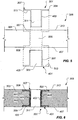
- Figure 1 depicts a structural component 101 exhibiting various exemplary types of damage that may be incurred during manufacture and/or in service. Note that, for each of the defect examples exhibited by structural component 101, the desired configuration of structural component 101 is shown in phantom.
- structural component 101 may define an elongated fastener hole 103 or 105, rather than substantially round fastener holes 107 and 109, respectively.
- Elongated fastener holes 103, 105 are positioned substantially correctly with respect to other features of structural component 101 but are not shaped appropriately. Elongated fastener holes 103, 105 may be produced by inferior drilling processes during manufacture.
- round fastener holes 107, 109 may become elongated (i.e., become elongated fastener holes 103, 105, respectively) while in service as a result of structural component 101 moving with respect to fasteners (not shown) extending through round fastener holes 107, 109.
- a fastener hole 111 that is larger in diameter than a desired fastener hole 113 may be drilled or otherwise generated in structural component 101. If structural component 101 is attached to another structural component (not shown) by a fastener (also not shown) extending through enlarged fastener hole 111, structural component 101 may not be sufficiently affixed to the other structural component, thus allowing structural component 101 to move with respect to the fastener or with respect to the other structural component. Furthermore, a desired fastener hole 115 may actually be produced in structural component 101 at an undesired location, as fastener hole 117, thus preventing structural component 101 from being attached to other structural components.
- two (or more) overlapping holes 118a and 118b may be generated in structural component 101. Whether either of holes 118a and 118b is in a desirable location, having overlapping holes is not acceptable. This undesirable configuration is often referred to as a "double-drilled" hole.
- Corners and other edges of structural component 101 may also be damaged during manufacture or while in service.
- a corner portion 119 and/or an edge portion 121 of structural component 101 may be broken off, worn away, or otherwise undesirably removed from structural component 101, leaving structural component 101 with improper edges 123, 125, respectively.
- structural component 101 may be trimmed or cut incorrectly, producing edges 123 and/or 125.
- Structural component 101 may not perform as designed because portion 119 or 121 is missing.
- One way of repairing damaged structural components is to add additional structural components, often known as "doublers," to reinforce the damaged structural component.
- doublers additional structural components
- a first doubler 201 and a second doubler 203 are added to structural component 101 so that a properly-sized fastener hole 205 can be provided for attaching structural component 101 to another structural component.
- the addition of such doublers changes the effective thickness of structural component 101 to include the thicknesses of doublers 201 and 203.
- the use of doublers may not be possible.
- US 4,577,450 discloses a waterproof floor panel fastening system for providing waterproof joints for use around entry doors.
- US 2005/0125946 discloses a drilled hole composite lug assembly typically used in joints such as clevis type joints.
- US 4,577,450 which is considered to represent the closest prior art for the subject-matter of the independent claims, discloses a device for repairing a structural component, comprising: a first member adapted for bonding to the structural component and having a flange and a sleeve extending from the flange, the sleeve being disposable in an opening of the structural component, the first member defining a passageway therethrough; and a second member adapted for bonding to the structural component and having a flange and a sleeve extending from the flange, the sleeve of the second member defining a passageway.
- US 4,577,450 discloses furthermore a method for repairing a structural component defining an opening, comprising the steps of: providing a first member having a flange and a sleeve extending from the flange, the first member defining a passageway; bonding the first member to the structural component such that the sleeve of the first member is disposed in the opening of the structural component; providing a second member having a flange and a sleeve extending from the flange, the second member defining a passageway; and bonding the second member to the structural component such that the sleeve of the second member is disposed in the passageway of the first member.
- the present invention provides a device for repairing a structural component, the structural component having an upper surface and a lower surface.
- the device includes a spacer sleeve which is disposable in an opening of the structural component, the exterior diameter of the spacer sleeve being adhesively bonded to the opening.
- the device further includes a first member adapted for bonding and having a flange and a sleeve extending from the flange.
- the flange of the first member is adapted to sit within a counterbore of the lower surface of the structural component, and has a desired thickness such that the flange sits flush with the lower surface of the structural component.
- the sleeve is disposable in a passageway defined by the spacer sleeve, the sleeve of the first member defining a passageway therethrough.
- the device further includes a second member adapted for bonding and having a flange and a sleeve extending from the flange.
- the flange of the second member is adapted to sit within a counterbore of the upper surface of the structural component, and has a desired thickness such that the flange of the second member sits flush with the upper surface of the structural component.
- a first adhesive is applied to the passageway defined by the spacer sleeve, the upper surface, and the lower surface, the first adhesive being utilized to adhesively bond the sleeve of the first member to the interior diameter of the spacer sleeve, to adhesively bond the flange of the first member to the lower surface, and to adhesively bond the flange of the second member to the upper surface; and a second adhesive is applied between the sleeve of the first member and the sleeve of the second member, the second adhesive being utilized to securely bond the second sleeve to the first sleeve.
- the present invention provides a repaired structural component, the structural component having an upper surface and a lower surface, the component comprising: a structural component defining an opening; and a device for repairing a structural component according to the first aspect of the invention, wherein: the spacer sleeve is disposed in the opening of the structural component, the exterior diameter of the spacer sleeve being adhesively bonded to the opening; the first member is bonded to the structural component and the spacer sleeve: the sleeve is disposed in the passageway defined by the spacer sleeve, and the second member is bonded to the structural component and the first member.
- the present invention provides a method for repairing a structural component defining an opening, comprising the steps of: counterboring a first counterbore on an upper surface of the structural component; counterboring a second counterbore on a lower surface of the structural component; providing a spacer sleeve defining a passageway; bonding the exterior diameter of the spacer sleeve to the opening of the structural component such that the spacer sleeve is disposed in the opening of the structural component; providing a first member having a flange and a sleeve extending from the flange, the first member defining a passageway and bonding the first member to the structural component and to the passageway defined by the spacer sleeve such that the sleeve of the first member is disposed in the passageway of the spacer sleeve, and such that the flange sits flush within the second counterbore of the lower surface of the structural component.
- the method further includes the steps of providing a second member having a flange and a sleeve extending from the flange, the second member defining a passageway and bonding the second member to the structural component and to the passageway defined by the first member such that the sleeve of the second member is disposed in the passageway of the first member, and such that the flange sits flush with the first counterbore of the upper surface of the structural component.
- the present invention provides significant advantages, including: (1) providing a means for repairing a structural component without adding significant weight to the repaired structural component; (2) providing a means for repairing a structural component without the use of doublers; (3) providing a means for repairing a structural component without impacting the interchangeability and/or the replaceability of the structural component; and (4) providing a means for repairing a structural component in a field environment.
- the present invention represents a device for repairing a structural component and a method of using the device.
- the device fills a portion of a hole, such as a defective fastener hole, defined by the structural component.
- the device when installed, defines a new fastener hole for use in fastening the structural component to another component in an assembly.
- the device substantially fills all of a hole, such as a defective fastener hole, defined by the structural component.
- a new hole is then generated through the repair device and the structural component.
- the device is attached to opposing sides of the structural component with a replacement structural portion attached therebetween.
- Figures 3-6 depict a first illustrative embodiment of a device 301 for repairing a defective structural component 303, forming repaired structural component 305.
- device 301 comprises a first member 401 slidingly mated with a second member 307.
- First member 401 comprises a flange 405 and a sleeve 501 extending from flange 405.
- First member 401 by way of flange 405 and sleeve 501, defines a passageway 503 therethrough.
- Second member 307 comprises a flange 309 and a sleeve 403 extending from flange 309.
- Second member 307 by way of flange 309 and sleeve 403, defines a passageway 311 therethrough.
- sleeve 403 of second member 307 slides into passageway 503 of first member 401.
- structural component 303 defines an opening 505 therethrough.
- Opening 505 may be an elongated or otherwise defective hole, such as a fastener hole 103 or 105 of Figure 1 , or may be a newly- formed hole that has an inappropriate diameter, such as fastener hole 111 of Figure 1 . Moreover, it may be desirable in certain situations to enlarge a defective hole or opening to remove damaged material adjacent the opening. For example, if structural component 303 comprises a composite material, structural component 303 may be delaminated adjacent a defective hole, such as fastener hole 103 or 105 of Figure 1 . Thus, it may be desirable to drill a new hole (i.e., opening 505) in the same location as the defective hole but having a larger diameter to remove the delaminated material. Moreover, if the holes are overlapping (e.g., holes 118a and 118b in Figure 1 ) it is desirable to drill a new hole (i.e., opening 505) encompassing the overlapping holes.
- the holes are overlapping (e.g., holes 118a and 118
- any repair to structural component 303 is substantially flush with an upper surface 313 of structural component 303 and substantially flush with a lower surface 407 of structural component 303. Accordingly, in the illustrated embodiment, structural component 03 is counterbored, generally at 507 and/or at 509, to receive flanges 309 and 405, respectively.
- opening 505 is prepared, if any preparation is needed, an adhesive is applied to portions of structural component 303 defining counterbores 507, 509 and or to lower surfaces 511, 513 of flanges 309, 405, respectively.
- Adhesive is applied to sleeve 501 of first member 401 and/or to opening 505 of structural component 303.
- first member 401 is placed into opening 505 of structural component 303, such that flange 405 is received into counterbore 509.
- Second member 307 is then placed into passageway 503 of first member 401, such that flange 309 of second member 307 is received in counterbore 507.
- Figure 6 depicts device 301 operably associated with structural component 303 to form repaired structural component 305.
- a first adhesive layer 603 is disposed between flange 405 of first member 401 and structural component 303 and a second adhesive layer 601 is disposed between flange 309 of second member 307 and structural component 303.
- an adhesive layer 701 extends between device 301 and structural. component 303 to retain device 301 with structural component 303.
- first member 401 it is preferable for first member 401 to be adhesively bonded to second member 307 by an adhesive layer 605.
- a fastener (not shown) is disposed through passageway 311 defined by second member 307 so that repaired structural component 305 may be attached to another member or component. Accordingly, the diameter of passageway 311 is sized appropriately for the fastener to be used.
- An outer diameter of sleeve 501 of first member 401 is sized to appropriately fill opening 505 with adhesive layer 701 disposed between sleeve 501 and structural component 303, if adhesive layer 701 is present.
- the outer diameter of sleeve 501 is sized to substantially fill opening 505 if no adhesive layer 701 is employed between sleeve 501 and structural component 303.
- flanges 309 and 405 preferably exhibit outer diameters of at least two times the diameter of passageway 311 of second member 307.
- each cover ply 703a or 703b comprises a single ply of woven fabric (e.g., fiberglass or the like) pre-impregnated with a resin compatible with the material of structural component 303 to minimize the change in thickness of repaired structural component 305 over structural component 303.
- woven fabric e.g., fiberglass or the like
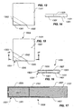
- Figure 8 depicts a second illustrative embodiment of a device 801 according to the present invention for repairing a defective structural component 803, forming repaired structural component 805.
- Device 801 comprises a spacer sleeve 807, a first member 809, and a second member 811.
- First member 809 and second member 811 correspond to first member 401 and second member 307, respectively, of Figures 3-7 .
- Spacer sleeve 807 may be produced in many different outer diameter sizes to accommodate the multitude of sizes of openings 505 of structural component 303 while having only a single or a few inner diameter sizes to cooperate with first and second members 809, 811.
- spacer sleeve 807 is placed in opening 505 defined by structural component 303, and adhesively bonded to structural component 803 by an adhesive layer 812 prior to installing first member 809 and second member 811.
- First member 809 is then inserted into a passageway 813 defined by spacer sleeve 807, adhesively bonded to structural component 803 by an adhesive layer 817, and adhesively bonded to spacer sleeve 807 by an adhesive layer 818.
- Second member 811 is then inserted into a passageway 815 defined by first member 809, adhesively bonded to structural component 803 by an adhesive layer 820, and adhesively bonded to first member 809 by an adhesive layer 822.
- a passageway 823 defined by second member 811 is configured to receive a fastener (not shown) for attaching repaired structural component 805 to another member or component.
- a fastener (not shown) for attaching repaired structural component 805 to another member or component.
- FIGs 9 and 10 depict an illustrative embodiment of a device 901 not according to the claimed invention for repairing a defective structural component 903, forming repaired structural component 905.
- device 901 comprises a plug 907 and a disc 1001.
- Plug 907 comprises a flange 909 and a solid shank 1003 extending from flange 909.
- flange 909 and disc 1001 are recessed into structural component 903.
- Device 901 is adhesively bonded to structural component 903.
- an adhesive layer 1005 extends along substantially all of an interface between plug 907 and structural component 903.
- plug 907 may be adhesively bonded to structural component 903 at flange 909.
- Disc 1001 is adhesively bonded to solid shank 1003 of plug 907 and to structural component 903 by an adhesive layer 1007.
- opening 911 is a fastener opening.
- Figures 11-17 depict a method not according to the claimed invention of repairing a defective structural component 1101 using a structural component repair device 1501.
- a corner 1103 (shown in phantom) of structural component 1101 has been broken away from structural component 1101.
- Figure 12 in some situations it is desirable to remove a further portion 1201 (shown in phantom) from structural component 1101. It is particularly advantageous to remove further material if structural component 1101 includes damaged material proximate a broken edge 1105.
- a lower tray 1301 of device 1501 has been adhesively bonded to a lower surface 1401 of structural component 1101 and to edges 1303, 1305 of structural component 1101.
- a replacement portion 1503 is adhesively bonded to lower tray 1301, to structural component 1101, and to an upper tray 1505 of device 1501.
- Upper tray 1505 is also adhesively bonded to an upper surface 1507 of structural component 1101 and to edges 1303, 1305 of structural component 1101.
- a repaired structural component 1509 comprises structural component 1101, replacement portion 1503, and device 1501 (i.e., upper tray 1505 and lower tray 1301) adhesively bonded to structural component 1101 and replacement portion 1503.
- Figure 17 depicts, in cross-section, one particular embodiment of a repaired structural component 1509 not according to the claimed invention.
- structural component 1101 and replacement portion 1503 are preferably recessed to accommodate device 1501.
- Replacement portion 1503 is adhesively bonded to upper tray 1505, lower tray 1301, and structural component 1101 by an adhesive layer 1701.
- Upper tray 1505 and lower tray 1301 are also adhesively bonded to structural component 1101 by adhesive layer 1701.
- adhesive layer 1701 is shown in Figure 17 as being contiguous, the scope of the present invention is not so limited. Rather, adhesive layer 1701 may comprise a plurality of separate adhesive layers bonding device 1501 and replacement portion 1503 to structural component 1101.
- a cover ply e.g., cover ply 703a or 703b of Figure 7
- a cover ply may be applied over upper tray 1505 and/or lower tray 1301, as described above in relation to Figure 7 .
- Figure 18 depicts an embodiment alternative to that of Figure 17 .
- a repaired structural component 1801 not according to the claimed invention comprises a structural component repair device 1802 having an upper tray 1803 and a lower tray 1805.
- Flanges 1807 and 1809 of upper tray 1803 and lower tray 1805 respectively overlap and are adhesively bonded to one another, edges 1303 and 1305 of structural component 1101, and an edge 1811 of replacement portion 1503 by adhesive layers 1811 a- 1811 d.
- the embodiment of Figure 18 generally corresponds to the embodiment of Figure 17 .
- surfaces of the device e.g., devices 301, 801, 901, 1501, or the like
- another component e.g., structural component 303, 803, 903, 1101, or the like
- texturing include roughening by grit (or other media) blasting and knurling.
- the device e.g., devices 301, 801, 901, 1501, or the like
- the device for repairing a defective structural component may comprise many different materials.
- the selection of a particular material for the device is implementation specific.
- the structural component e.g., structural component 303, 803, 903, 1101, or the like
- the repair device preferably comprises aluminum or stainless steel.
- the structural component comprises a carbon- or graphite-epoxy composite material
- the repair device preferably comprises a stainless steel or a titanium alloy.
- the repair device may also comprise a composite material, such as carbon- or graphite- reinforced polymeric materials (e.g., carbon- or graphite-reinforced epoxy, carbon- or graphite-reinforced polyetheretherketone polymer, or the like).
- a composite material such as carbon- or graphite- reinforced polymeric materials (e.g., carbon- or graphite-reinforced epoxy, carbon- or graphite-reinforced polyetheretherketone polymer, or the like).
- elements comprising the device according to the present invention for repairing a defective structural component are made as thin as possible.
- a flange and a sleeve of the device exhibit thicknesses, in one embodiment, of about 0.2 millimeters.
- any of the elements of the present invention may be trimmed, cut, or otherwise adapted to be operable with a structural component at the time of assembly with the structural component.
Landscapes
- Engineering & Computer Science (AREA)
- Mechanical Engineering (AREA)
- General Engineering & Computer Science (AREA)
- Manufacturing & Machinery (AREA)
- Transportation (AREA)
- Aviation & Aerospace Engineering (AREA)
- Working Measures On Existing Buildindgs (AREA)
Claims (10)
- Un dispositif (801) pour la réparation d'un composant de structure (803), le composant de structure possédant une surface supérieure et une surface inférieure, le dispositif comprenant :un manchon d'espacement (807) pouvant être disposé dans une ouverture (505) du composant de structure, le diamètre extérieur du manchon d'espacement étant lié de manière adhésive à l'ouverture,un premier élément (809) adapté pour une liaison et possédant :une bride (405), la bride étant adaptée de façon à se loger à l'intérieur d'un contre-alésage de la surface inférieure du composant de structure, la bride possédant une épaisseur souhaitée de sorte que la bride soit à fleur avec la surface inférieure du composant de structure, etun manchon (501) s'étendant à partir de la bride, le manchon pouvant être disposé dans un canal défini par le manchon d'espacement, le manchon du premier élément définissant a canal au travers de celui-ciun deuxième élément (811) adapté pour une liaison et possédant :une bride (309), la bride étant adaptée de façon à se loger à l'intérieur d'un contre-alésage de la surface supérieure du composant de structure, la bride possédant une épaisseur souhaitée de sorte que la bride soit à fleur avec la surface supérieure du composant de structure, etun manchon (403) s'étendant à partir de la bride, le manchon du deuxième élément définissant un canal, le manchon étant adapté de façon à se loger à l'intérieur du canal défini par le premier élément,un premier adhésif (817, 818, 820) appliqué au canal défini par le manchon d'espacement, la surface supérieure et la surface inférieure, le premier adhésif étant utilisé de façon à lier de manière adhésive le manchon du premier élément au diamètre intérieur du manchon d'espacement, de façon à lier de manière adhésive la bride du premier élément à la surface inférieure et à lier de manière adhésive la bride du deuxième élément à la surface supérieure, etun deuxième adhésif (822) appliqué entre le manchon du premier élément et le manchon du deuxième élément, le deuxième adhésif étant utilisé de façon à lier de manière fixe le deuxième manchon au premier manchon.
- Un composant de structure réparé, le composant de structure possédant une surface supérieure et une surface inférieure, le composant comprenant :un composant de structure définissant une ouverture, etun dispositif destiné à la réparation d'un composant de structure selon la Revendication 1, où :le manchon d'espacement est disposé dans l'ouverture du composant de structure, le diamètre extérieur du manchon d'espacement étant lié de manière adhésive à l'ouverture,le premier élément est lié au composant de structure et au manchon d'espacement,le manchon est disposé dans le canal défini par le manchon d'espacement,le deuxième élément est lié au composant de structure et au premier élément.
- Le composant de structure réparé selon la Revendication 2, où le composant de structure définit un évidement destiné à recevoir un élément parmi la bride du premier élément et la bride du deuxième élément.
- Le composant de structure réparé selon la Revendication 2, où une surface du manchon d'espacement est texturée.
- Le composant de structure réparé selon la Revendication 2, comprenant en outre :un pli de couverture lié au composant de structure et à au moins un élément parmi la bride du premier élément et la bride du deuxième élément.
- Le composant de structure réparé selon la Revendication 2, où au moins une surface du premier élément et du deuxième élément est texturée.
- Un procédé pour la réparation d'un composant de structure définissant une ouverture, comprenant les opérations suivantes :le contre-alésage d'un premier contre-alésage sur une surface supérieure du composant de structure,le contre-alésage d'un deuxième contre-alésage sur une surface inférieure du composant de structure,la fourniture d'un manchon d'espacement définissant un canal,la liaison du diamètre extérieur du manchon d'espacement à l'ouverture du composant de structure de sorte que le manchon d'espacement soit disposé dans l'ouverture du composant de structure,la fourniture d'un premier élément possédant une bride et un manchon s'étendant à partir de la bride, le premier élément définissant un canal,la liaison du premier élément au composant de structure et au canal défini par le manchon d'espacement de sorte que le manchon du premier élément soit disposé dans le canal du manchon d'espacement et de sorte que la bride soit placée à fleur à l'intérieur du deuxième contre-alésage de la surface inférieure du composant de structure,la fourniture d'un deuxième élément possédant une bride et un manchon s'étendant à partir de la bride, le deuxième élément définissant un canal, etla liaison du deuxième élément au composant de structure et au canal défini par le premier élément de sorte que le manchon du deuxième élément soit disposé dans le canal du premier élément et de sorte que la bride soit à fleur avec le premier contre-alésage de la surface supérieure du composant de structure.
- Le procédé, selon la Revendication 7, comprenant en outre l'opération suivante :l'application d'un pli de couverture sur au moins un élément parmi le premier élément et le deuxième élément.
- Le procédé, selon la Revendication 7, comprenant en outre l'opération suivante :le texturage d'au moins une surface du premier élément et du deuxième élément.
- Le procédé, selon la Revendication 7, comprenant en outre l'opération suivante :l'évidement du composant de structure de façon à recevoir au moins un élément parmi la bride du premier élément et la bride du deuxième élément.
Applications Claiming Priority (1)
| Application Number | Priority Date | Filing Date | Title |
|---|---|---|---|
| PCT/US2006/018240 WO2007133198A1 (fr) | 2006-05-11 | 2006-05-11 | Dispositif et procédé pour réparer des composants structuraux |
Publications (3)
| Publication Number | Publication Date |
|---|---|
| EP2015889A1 EP2015889A1 (fr) | 2009-01-21 |
| EP2015889A4 EP2015889A4 (fr) | 2013-01-02 |
| EP2015889B1 true EP2015889B1 (fr) | 2014-07-09 |
Family
ID=38694176
Family Applications (1)
| Application Number | Title | Priority Date | Filing Date |
|---|---|---|---|
| EP06759562.9A Active EP2015889B1 (fr) | 2006-05-11 | 2006-05-11 | Dispositif et procédé pour réparer des composants structuraux |
Country Status (11)
| Country | Link |
|---|---|
| US (2) | US8152952B2 (fr) |
| EP (1) | EP2015889B1 (fr) |
| JP (1) | JP2009536884A (fr) |
| CN (1) | CN101437645B (fr) |
| AU (1) | AU2006343591A1 (fr) |
| BR (1) | BRPI0621639A2 (fr) |
| CA (2) | CA2650272C (fr) |
| DE (1) | DE06759562T1 (fr) |
| EA (1) | EA200802319A1 (fr) |
| MX (1) | MX2008014396A (fr) |
| WO (1) | WO2007133198A1 (fr) |
Families Citing this family (25)
| Publication number | Priority date | Publication date | Assignee | Title |
|---|---|---|---|---|
| FR2956054B1 (fr) | 2010-02-10 | 2012-04-27 | Snecma | Procede de reparation d'une bride d'un carter |
| JPWO2011105540A1 (ja) * | 2010-02-26 | 2013-06-20 | 三菱重工業株式会社 | 複合材の修理方法およびこれを用いた複合材 |
| CN103492172B (zh) * | 2010-11-05 | 2016-03-02 | 贝尔直升机泰克斯特龙公司 | 可模制的飞离工具结构系统 |
| FR2970238B1 (fr) * | 2011-01-07 | 2013-01-25 | Airbus Operations Sas | Piece et procede de reparation d'une structure endommagee, en particulier de peau d'aeronef, ainsi qu'un kit de reparation de mise en oeuvre |
| DE112012003671T5 (de) * | 2011-09-04 | 2014-07-03 | Honda Motor Co., Ltd. | Faserverstärktes Kunststoffelement und Verfahren zur Herstellung eines faserverstärkten Kunststoffelements |
| US8784604B2 (en) * | 2011-10-13 | 2014-07-22 | Textron Innovations Inc. | Method and apparatus for out-of-autoclave adhesive shear bonding of structures |
| US9849640B2 (en) * | 2012-03-28 | 2017-12-26 | Bell Helicopter Textron Inc. | Processes for repairing complex laminated composites |
| CN103028889B (zh) * | 2012-12-25 | 2016-03-16 | 西南铝业(集团)有限责任公司 | 一种挤压筒内套的修复方法 |
| US10060295B2 (en) | 2013-03-01 | 2018-08-28 | United Technologies Corporation | Repair of surface damage at edges of cellular panels |
| US9279684B2 (en) * | 2013-04-02 | 2016-03-08 | Rosemount Aerospace Inc. | Air data probe sense port repair |
| EP3036445B1 (fr) * | 2013-08-20 | 2019-12-18 | United Technologies Corporation | Remplacement d'une ouverture par une bague annulaire dans un élément composite stratifié |
| US20150108828A1 (en) * | 2013-10-21 | 2015-04-23 | Caterpillar Inc. | Method of remanufacturing a wheel housing |
| US10288097B2 (en) * | 2014-08-06 | 2019-05-14 | Honda Motor Co., Ltd. | Fiber-reinforced resin member and method for producing fiber-reinforced resin member |
| FR3025127B1 (fr) * | 2014-08-28 | 2017-03-17 | Snecma | Reparation d'un assemblage comprenant un corps principal et un renfort |
| US10392132B2 (en) * | 2016-07-29 | 2019-08-27 | The Boeing Company | Curved aircraft substructure repair systems and methods |
| FR3055565B1 (fr) * | 2016-09-02 | 2018-08-17 | Safran Aircraft Engines | Douillage en vis-a-vis pour la reparation de trous de serrage |
| DE102018107482B4 (de) | 2018-03-28 | 2022-09-01 | Airbus Helicopters Deutschland GmbH | Verfahren zum austausch eines in eine sandwich-platte integrierten lastaufnahme- oder lastverteilungselements |
| US10518597B1 (en) * | 2018-10-05 | 2019-12-31 | Shock Therapy, LLC | Toe link support and method of supporting a toe link |
| EP3639969B1 (fr) * | 2018-10-17 | 2020-12-02 | LEONARDO S.p.A. | Procédé et outil de reconditionnement d'un filetage endommagé |
| DE102019107202A1 (de) * | 2019-03-20 | 2020-09-24 | Airbus Operations Gmbh | Bearbeitungsverfahren, Applikationswerkzeug und Bearbeitungsanordnung zum Ändern oder Reparieren einer Oberflächenstelle einer Werkstückoberfläche eines Faserverbundwerkstücks |
| CN109940337B (zh) * | 2019-03-28 | 2020-11-10 | 正茂集团有限责任公司 | 锚链弯环机中心胎具定位孔的修复方法 |
| DE102019110464A1 (de) * | 2019-04-23 | 2020-10-29 | Carl Zeiss Fixture Systems Gmbh | Vorrichtung zur Halterung eines zu vermessenden Karosseriebauteils in einer Referenzlage |
| US11566645B2 (en) * | 2020-07-22 | 2023-01-31 | Li-Sheng Lan | Positioning and fastening system for combining planks |
| US20220041519A1 (en) * | 2020-08-05 | 2022-02-10 | General Electric Company | Method for repairing composite components using filler material |
| CN112756904A (zh) * | 2020-12-28 | 2021-05-07 | 国营第六一六厂 | 一种五轴镗床再制造修复用导向套及修复方法 |
Citations (1)
| Publication number | Priority date | Publication date | Assignee | Title |
|---|---|---|---|---|
| JPH08169057A (ja) * | 1994-12-16 | 1996-07-02 | Showa Aircraft Ind Co Ltd | 接着治具およびその製作方法 |
Family Cites Families (27)
| Publication number | Priority date | Publication date | Assignee | Title |
|---|---|---|---|---|
| US3252493A (en) * | 1964-05-22 | 1966-05-24 | Gen Dynamics Corp | Three part fastener with spacer means |
| US4112993A (en) * | 1977-04-26 | 1978-09-12 | Sps Technologies, Inc. | Grommet assembly |
| FR2511908A1 (fr) * | 1981-08-26 | 1983-03-04 | Snecma | Procede de brasage-diffusion destine aux pieces en superalliages |
| US4521732A (en) * | 1982-03-16 | 1985-06-04 | Pegg David T | Pulse sequence for use in performing nuclear magnetic resonance spectroscopy |
| EP0144320B1 (fr) * | 1983-06-06 | 1988-01-07 | The Boeing Company | Systeme d'accrochage de panneau de plancher impermeable, accessible d'en haut |
| DE3474594D1 (en) * | 1984-03-29 | 1988-11-17 | Oxford Res Syst | Method of operating a nuclear magnetic resonance spectrometer |
| GB2169372B (en) * | 1985-01-07 | 1988-09-14 | Rexnord Inc | Improvements in and relating to fasteners |
| ZA87954B (en) * | 1986-02-18 | 1987-09-30 | Coors Co Adolph | Apparatus and method for trimming a can body |
| US4817264A (en) | 1987-08-10 | 1989-04-04 | Shur-Lok Corporation | Fastener and assembly process |
| US5085748A (en) * | 1989-01-24 | 1992-02-04 | Nippon Steel Chemical Co., Ltd. | Process for enriching carbon 13 |
| US5145893A (en) * | 1989-03-21 | 1992-09-08 | Ciba-Geigy Corporation | Non-migrating 1-hydrocarbyloxy hindered amine derivatives as polymer stabilizers |
| GB8929005D0 (en) * | 1989-12-22 | 1990-02-28 | Refurbished Turbine Components | Turbine blade repair |
| FR2667531B1 (fr) * | 1990-10-08 | 1993-01-22 | Framatome Sa | Procede et dispositif de pose d'un filet rapporte helicouidal dans une ouverture taraudee de grand diametre et utilisation de ce procede et de ce dispositif. |
| US5093957A (en) * | 1991-07-08 | 1992-03-10 | Atr International, Inc. | Compression fitting for use in a two-sided honeycomb panel |
| AU668691B2 (en) * | 1991-08-09 | 1996-05-16 | Nycomed Innovation Ab | Use of persistent free-radicals in magnetic resonance imaging |
| JP2002508687A (ja) * | 1997-06-19 | 2002-03-19 | ナイコムド イメージング エーエス | 磁気共鳴(mr)イメージング剤の生体外分極を含むオーバーハウザー磁気共鳴画像(ormi)法 |
| US6278893B1 (en) * | 1998-01-05 | 2001-08-21 | Nycomed Imaging As | Method of magnetic resonance imaging of a sample with ex vivo polarization of an MR imaging agent |
| GB9801398D0 (en) * | 1998-01-22 | 1998-03-18 | Anggard Erik E | Chemical compounds |
| US20020058869A1 (en) * | 1999-05-19 | 2002-05-16 | Oskar Axelsson | Methods of magnetic resonance imaging (MRI) using contract agent solutions formed from the dissolution of hyperpolarised materials |
| US6295834B1 (en) * | 1999-06-30 | 2001-10-02 | Medi-Physics, Inc. | NMR polarization monitoring coils, hyperpolarizers with same, and methods for determining the polarization level of accumulated hyperpolarized noble gases during production |
| US6949169B2 (en) * | 2000-07-12 | 2005-09-27 | University Of New Hampshire | Apparatus and method for polarizing polarizable nuclear species |
| WO2002036005A1 (fr) * | 2000-11-03 | 2002-05-10 | Amersham Health As | Procedes et dispositifs destines a des echantillons rmn polarises |
| US20040049108A1 (en) * | 2000-11-03 | 2004-03-11 | Ardenkjaer-Larsen Jan Henrik | Methods and devices for polarised nmr samples |
| JP2002302121A (ja) | 2001-04-06 | 2002-10-15 | Futawa Co Ltd | 構造体 |
| US6515260B1 (en) * | 2001-11-07 | 2003-02-04 | Varian, Inc. | Method and apparatus for rapid heating of NMR samples |
| US7351402B2 (en) * | 2003-08-21 | 2008-04-01 | Massachusetts Institute Of Technology | Polarizing agents for dynamic nuclear polarization |
| US7047596B2 (en) | 2003-12-09 | 2006-05-23 | Sikorsky Aircraft Corp. | Structural bushing application for highly loaded composites lugs |
-
2006
- 2006-05-11 EP EP06759562.9A patent/EP2015889B1/fr active Active
- 2006-05-11 BR BRPI0621639-0A patent/BRPI0621639A2/pt not_active Application Discontinuation
- 2006-05-11 CA CA2650272A patent/CA2650272C/fr active Active
- 2006-05-11 WO PCT/US2006/018240 patent/WO2007133198A1/fr active Application Filing
- 2006-05-11 CN CN2006800545473A patent/CN101437645B/zh not_active Expired - Fee Related
- 2006-05-11 US US12/300,052 patent/US8152952B2/en not_active Expired - Fee Related
- 2006-05-11 EA EA200802319A patent/EA200802319A1/ru unknown
- 2006-05-11 MX MX2008014396A patent/MX2008014396A/es unknown
- 2006-05-11 DE DE06759562T patent/DE06759562T1/de active Pending
- 2006-05-11 JP JP2009509526A patent/JP2009536884A/ja active Pending
- 2006-05-11 AU AU2006343591A patent/AU2006343591A1/en not_active Abandoned
- 2006-05-11 CA CA2777788A patent/CA2777788C/fr active Active
-
2012
- 2012-04-02 US US13/437,665 patent/US8808823B2/en active Active
Patent Citations (1)
| Publication number | Priority date | Publication date | Assignee | Title |
|---|---|---|---|---|
| JPH08169057A (ja) * | 1994-12-16 | 1996-07-02 | Showa Aircraft Ind Co Ltd | 接着治具およびその製作方法 |
Non-Patent Citations (1)
| Title |
|---|
| BAKER A A ED - MIDDLETON DONALD H: "Repair Techniques for Composite Structures", 1 January 1990, COMPOSITE MATERIALS IN AIRCRAFT STRUCTURES, LONGMAN, NEW YORK, PAGE(S) 207 - 227, ISBN: 978-0-582-01712-2, XP008103764 * |
Also Published As
| Publication number | Publication date |
|---|---|
| CA2650272C (fr) | 2012-08-28 |
| US20090208691A1 (en) | 2009-08-20 |
| JP2009536884A (ja) | 2009-10-22 |
| CN101437645B (zh) | 2010-12-01 |
| CA2777788C (fr) | 2016-06-28 |
| CA2777788A1 (fr) | 2007-11-22 |
| EP2015889A1 (fr) | 2009-01-21 |
| EP2015889A4 (fr) | 2013-01-02 |
| CN101437645A (zh) | 2009-05-20 |
| MX2008014396A (es) | 2009-02-06 |
| WO2007133198A9 (fr) | 2008-04-03 |
| US20120189807A1 (en) | 2012-07-26 |
| EA200802319A1 (ru) | 2009-06-30 |
| AU2006343591A1 (en) | 2007-11-22 |
| DE06759562T1 (de) | 2009-07-30 |
| US8808823B2 (en) | 2014-08-19 |
| CA2650272A1 (fr) | 2007-11-22 |
| BRPI0621639A2 (pt) | 2011-12-20 |
| US8152952B2 (en) | 2012-04-10 |
| WO2007133198A1 (fr) | 2007-11-22 |
Similar Documents
| Publication | Publication Date | Title |
|---|---|---|
| EP2015889B1 (fr) | Dispositif et procédé pour réparer des composants structuraux | |
| US10689086B2 (en) | Splice joints for composite aircraft fuselages and other structures | |
| US9592901B2 (en) | Multi-directional load joint system | |
| US7807249B2 (en) | Composite article having reinforcing fibers oriented to suppress or delay ply splitting | |
| US9347473B2 (en) | Apparatus for joining members and assembly thereof | |
| EP3036445B1 (fr) | Remplacement d'une ouverture par une bague annulaire dans un élément composite stratifié | |
| US20060067806A1 (en) | Unified multi-part head for a staked fastener | |
| EP2040057A1 (fr) | Procédé pour le contrôle de qualité d'une liaison collée structurale | |
| US20040194284A1 (en) | Adhesive encapsulated blind rivet system | |
| US20120128408A1 (en) | Composite sandwich shell edge joint | |
| EP3482917B1 (fr) | Jonction des éléments | |
| KR20090013791A (ko) | 구조 요소의 수리용 장치 및 방법 | |
| EP0180865A2 (fr) | Pièce de réparation applicable sur la face inaccessible d'un panneau | |
| WO2003011594A1 (fr) | Moule a panneau stratifie et procede de production correspondant | |
| Crilly | Producibility Considerations in Adhesive Bonded Structures |
Legal Events
| Date | Code | Title | Description |
|---|---|---|---|
| PUAI | Public reference made under article 153(3) epc to a published international application that has entered the european phase |
Free format text: ORIGINAL CODE: 0009012 |
|
| 17P | Request for examination filed |
Effective date: 20081126 |
|
| AK | Designated contracting states |
Kind code of ref document: A1 Designated state(s): AT BE BG CH CY CZ DE DK EE ES FI FR GB GR HU IE IS IT LI LT LU LV MC NL PL PT RO SE SI SK TR |
|
| AX | Request for extension of the european patent |
Extension state: AL BA HR MK YU |
|
| DAX | Request for extension of the european patent (deleted) | ||
| RBV | Designated contracting states (corrected) |
Designated state(s): DE FR GB IT |
|
| DET | De: translation of patent claims | ||
| A4 | Supplementary search report drawn up and despatched |
Effective date: 20121129 |
|
| RIC1 | Information provided on ipc code assigned before grant |
Ipc: F16B 5/01 20060101AFI20121123BHEP Ipc: B29C 73/04 20060101ALN20121123BHEP Ipc: B64F 5/00 20060101ALN20121123BHEP Ipc: B23P 6/00 20060101ALI20121123BHEP |
|
| 17Q | First examination report despatched |
Effective date: 20130607 |
|
| REG | Reference to a national code |
Ref country code: DE Ref legal event code: R079 Ref document number: 602006042215 Country of ref document: DE Free format text: PREVIOUS MAIN CLASS: B23K0031020000 Ipc: F16B0005010000 |
|
| GRAP | Despatch of communication of intention to grant a patent |
Free format text: ORIGINAL CODE: EPIDOSNIGR1 |
|
| RIC1 | Information provided on ipc code assigned before grant |
Ipc: F16B 5/01 20060101AFI20140310BHEP Ipc: B23P 6/00 20060101ALI20140310BHEP Ipc: B29C 73/04 20060101ALN20140310BHEP Ipc: B64F 5/00 20060101ALN20140310BHEP |
|
| INTG | Intention to grant announced |
Effective date: 20140328 |
|
| GRAS | Grant fee paid |
Free format text: ORIGINAL CODE: EPIDOSNIGR3 |
|
| GRAA | (expected) grant |
Free format text: ORIGINAL CODE: 0009210 |
|
| AK | Designated contracting states |
Kind code of ref document: B1 Designated state(s): DE FR GB IT |
|
| REG | Reference to a national code |
Ref country code: GB Ref legal event code: FG4D |
|
| REG | Reference to a national code |
Ref country code: DE Ref legal event code: R096 Ref document number: 602006042215 Country of ref document: DE Effective date: 20140814 |
|
| REG | Reference to a national code |
Ref country code: DE Ref legal event code: R097 Ref document number: 602006042215 Country of ref document: DE |
|
| PLBE | No opposition filed within time limit |
Free format text: ORIGINAL CODE: 0009261 |
|
| STAA | Information on the status of an ep patent application or granted ep patent |
Free format text: STATUS: NO OPPOSITION FILED WITHIN TIME LIMIT |
|
| 26N | No opposition filed |
Effective date: 20150410 |
|
| REG | Reference to a national code |
Ref country code: FR Ref legal event code: PLFP Year of fee payment: 11 |
|
| REG | Reference to a national code |
Ref country code: FR Ref legal event code: PLFP Year of fee payment: 12 |
|
| REG | Reference to a national code |
Ref country code: FR Ref legal event code: PLFP Year of fee payment: 13 |
|
| PGFP | Annual fee paid to national office [announced via postgrant information from national office to epo] |
Ref country code: DE Payment date: 20220527 Year of fee payment: 17 |
|
| PGFP | Annual fee paid to national office [announced via postgrant information from national office to epo] |
Ref country code: IT Payment date: 20230519 Year of fee payment: 18 Ref country code: FR Payment date: 20230525 Year of fee payment: 18 |
|
| PGFP | Annual fee paid to national office [announced via postgrant information from national office to epo] |
Ref country code: GB Payment date: 20230529 Year of fee payment: 18 |
|
| REG | Reference to a national code |
Ref country code: DE Ref legal event code: R119 Ref document number: 602006042215 Country of ref document: DE |
|
| PG25 | Lapsed in a contracting state [announced via postgrant information from national office to epo] |
Ref country code: DE Free format text: LAPSE BECAUSE OF NON-PAYMENT OF DUE FEES Effective date: 20231201 |