EP2014891A1 - Radiator for small-sized vehicle - Google Patents
Radiator for small-sized vehicle Download PDFInfo
- Publication number
- EP2014891A1 EP2014891A1 EP08010450A EP08010450A EP2014891A1 EP 2014891 A1 EP2014891 A1 EP 2014891A1 EP 08010450 A EP08010450 A EP 08010450A EP 08010450 A EP08010450 A EP 08010450A EP 2014891 A1 EP2014891 A1 EP 2014891A1
- Authority
- EP
- European Patent Office
- Prior art keywords
- radiator
- crankcase
- cooling fan
- cooling
- exhaust port
- Prior art date
- Legal status (The legal status is an assumption and is not a legal conclusion. Google has not performed a legal analysis and makes no representation as to the accuracy of the status listed.)
- Granted
Links
- 238000001816 cooling Methods 0.000 claims abstract description 101
- XLYOFNOQVPJJNP-UHFFFAOYSA-N water Substances O XLYOFNOQVPJJNP-UHFFFAOYSA-N 0.000 claims abstract description 40
- 239000000498 cooling water Substances 0.000 description 26
- 230000005540 biological transmission Effects 0.000 description 23
- 230000000740 bleeding effect Effects 0.000 description 4
- 238000013459 approach Methods 0.000 description 3
- 239000002828 fuel tank Substances 0.000 description 3
- 230000003014 reinforcing effect Effects 0.000 description 2
- 229920003002 synthetic resin Polymers 0.000 description 2
- 239000000057 synthetic resin Substances 0.000 description 2
- 238000010792 warming Methods 0.000 description 2
- 238000003466 welding Methods 0.000 description 2
- 235000014676 Phragmites communis Nutrition 0.000 description 1
- 230000008878 coupling Effects 0.000 description 1
- 238000010168 coupling process Methods 0.000 description 1
- 238000005859 coupling reaction Methods 0.000 description 1
- 230000007423 decrease Effects 0.000 description 1
- 230000000694 effects Effects 0.000 description 1
- 239000000446 fuel Substances 0.000 description 1
- 238000002347 injection Methods 0.000 description 1
- 239000007924 injection Substances 0.000 description 1
- 230000000630 rising effect Effects 0.000 description 1
- 238000011144 upstream manufacturing Methods 0.000 description 1
- 238000009423 ventilation Methods 0.000 description 1
Images




Classifications
-
- F—MECHANICAL ENGINEERING; LIGHTING; HEATING; WEAPONS; BLASTING
- F01—MACHINES OR ENGINES IN GENERAL; ENGINE PLANTS IN GENERAL; STEAM ENGINES
- F01P—COOLING OF MACHINES OR ENGINES IN GENERAL; COOLING OF INTERNAL-COMBUSTION ENGINES
- F01P11/00—Component parts, details, or accessories not provided for in, or of interest apart from, groups F01P1/00 - F01P9/00
- F01P11/10—Guiding or ducting cooling-air, to, or from, liquid-to-air heat exchangers
-
- F—MECHANICAL ENGINEERING; LIGHTING; HEATING; WEAPONS; BLASTING
- F01—MACHINES OR ENGINES IN GENERAL; ENGINE PLANTS IN GENERAL; STEAM ENGINES
- F01P—COOLING OF MACHINES OR ENGINES IN GENERAL; COOLING OF INTERNAL-COMBUSTION ENGINES
- F01P2050/00—Applications
- F01P2050/16—Motor-cycles
-
- F—MECHANICAL ENGINEERING; LIGHTING; HEATING; WEAPONS; BLASTING
- F01—MACHINES OR ENGINES IN GENERAL; ENGINE PLANTS IN GENERAL; STEAM ENGINES
- F01P—COOLING OF MACHINES OR ENGINES IN GENERAL; COOLING OF INTERNAL-COMBUSTION ENGINES
- F01P5/00—Pumping cooling-air or liquid coolants
- F01P5/02—Pumping cooling-air; Arrangements of cooling-air pumps, e.g. fans or blowers
- F01P5/06—Guiding or ducting air to, or from, ducted fans
Definitions
- the present invention relates to a radiator for a small-sized vehicle where an engine main unit provided with a water jacket is mounted on a body frame, a radiator is arranged on the side of a crankcase forming a part of the engine main unit, a cooling fan that sucks cooling wind to let the cooling wind pass in the radiator is attached to one end of a crankshaft rotatably supported by the crankcase and is arranged inside the radiator and a shroud having an exhaust port and covering the cooling fan from the side is provided between the radiator and the crankcase.
- Patent Document No. JP-A 2005-233012 that discloses that a radiator is arranged outside a cooling fan provided to one end of a crankshaft and an exhaust port is provided to a shroud provided between a crankcase and the radiator and covering the cooling fan from the side is known.
- a generator is arranged on the reverse side to the radiator of the cooling fan, annular space is formed on the side of the generator, cooling wind which is sucked by the cooling fan and passes the radiator flows to the exhaust port, however, as the cooling wind also flows to the side of the annular space around the generator, the smooth flow to the exhaust port of the cooling wind is hindered, and as the efficiency of the cooling fan drops, cooling efficiency is deteriorated.
- the invention is made in view of such a situation and provides a radiator for a small-sized vehicle where cooling efficiency is enhanced by making cooling wind smoothly flow from a cooling fan to an exhaust port.
- the invention according to Claim 1 is based upon a radiator for a small-sized vehicle where an engine main unit provided with a water jacket is mounted on a body frame, a radiator is arranged on the side of a crankcase forming a part of the engine main unit, a cooling fan that sucks cooling wind to pass the radiator is attached to one end of a crankshaft rotatably supported by the crankcase and is arranged inside the radiator and a shroud having an exhaust port and covering the cooling fan from the side is provided between the radiator and the crankcase, and has a characteristic that a current plate for obstructing a flow of cooling wind from the cooling fan to the side of the crankcase in a part corresponding to the exhaust port is fixed not on the sides of the exhaust port and the cooling fan but on the side of the crankcase.
- the invention according to Claim 2 is based upon the configuration of the invention according to Claim 1 and has a characteristic that the current plate is attached to the shroud.
- the invention according to Claim 3 is based upon the configuration of the invention according to Claim 1 or 2 and has a characteristic that the current plate is formed in the shape of a circular arc along a rotational locus of an outermost end in a radial direction of the cooling fan in a side view.
- the invention according to Claim 4 is based upon the configuration of the invention according to any of Claims 1 to 3 and has a characteristic that a generator is arranged between the cooling fan and the crankcase and a turned part extended from an inner end of the current plate to the side of the crankcase is integrated with the current plate arranged outside the generator.
- the current plate is attached to the shroud and the shroud to which the current plate is attached can be attached to the crankcase, the current plate does not obstruct the attachment when the cooling fan is attached to the crankshaft, compared with a case that a current plate is attached to a crankcase and ease of assembly can be enhanced.
- the current plate is formed in the shape of the circular arc along the rotational locus of the outermost end in the radial direction of the cooling fan in the side view, the flow from the cooling fan to the side of the crankcase of cooling wind can be more effectively hindered.
- turbulence is prevented from being caused in a small quantity of cooling wind flowing between the generator and the current plate by opposing the turned part turned on the side of the crankcase from the inner end of the current plate to the periphery of the generator and the cooling wind can more smoothly flow on the side of the exhaust port.
- a body frame F of the scooter type motorcycle which is a small-sized vehicle is provided with: a head pipe 13 that steerably supports a front fork 11 that journals a front wheel WF at its lower end and straddles the front wheel WF and a steering handlebar 12 coupled to an upper end of the front fork 11; a cylindrical main pipe 14 extended backward and downward from the head pipe 13; a pair of right and left lower frames 15 connected to a lower part of the main pipe 14 and extended backward; a cross pipe 16 that connects rear ends of both lower frames 15; a pair of right and left rear frame pipes 17 each front end of which is linked to each of both ends of the cross pipe 16; and upper frames 18 each of which couples an intermediate part of the main pipe 14 and each intermediate part of both rear frame pipes 17 on the upsides of both lower frames 15.
- the lower frames 15 are connected to both right and left sides of the lower part of the main pipe 14 by welding, are extended on both sides, further are bent on the rear sides, and are extended backward. Each rear end of the lower frames 15 is connected to each of both right and left ends of the cross pipe 16 by welding.
- the power unit P including a water-cooled single-cylinder engine E arranged on the front side of a rear wheel WR and a transmission M arranged on the left side of the rear wheel WR is supported vertically rockably by each front of both rear frame pipes 17 of the body frame F and the rear wheel WR is journalled to the rear of the power unit P.
- the transmission M is linked to a crank case 21 of the engine E, and is housed in a transmission case 22 extended to the left side of the rear wheel WR.
- a rear cushion unit 23 is provided between the rear of the transmission case 22 and the left rear frame pipe 17 out of the pair of right and left rear frame pipes 17.
- a goods housing 24 that can house a helmet and others is arranged from the upside of the engine E to the front side of the engine E between both rear frame pipes 17 and between both upper frames 18 and the rear of the goods housing 24 is covered with a seat 25 arranged at the back of the head pipe 13 from the upside.
- a fuel tank 26 covered with the rear of the seat 25 from the upside is arranged between the rears of both rear frame pipes 17 at the back of the goods housing 24, and the goods housing 24 and the fuel tank 26 are supported by the body frame F.
- a part of the engine E, the body frame F, the goods housing 24 and the fuel tank 26 are covered with a body cover 29, and a pair of right and left step floors 27 for putting feet of a rider seated on the seat 25 and a floor tunnel 28 rising upward between both step floors 27 are formed inside the body cover 29.
- the floor tunnel 28 includes: a tunnel main part 30 which is supported by the pair of right and left upper frames 18, which ranges to each inner end of both step floors 27, which rises upward and a part of an upper part of which is open; and a cover 31 that openably closes an opening of the upper part of the tunnel main part 30.
- the front of the goods housing 24 is housed in the floor tunnel 28.
- a hinge mechanism (not shown) for openably supporting the seat 25 is provided between the front of the seat 25 and the main pipe 14, the seat 25 can be turned forward and diagonally upward so as to enable housing and extracting goods such as a helmet in/from the goods housing 24, and the cover 31 is turned together with the seat 25 so as to open the upside of the front of the goods housing 24.
- the main unit 33 of the engine E is provided with: a crankcase 21 that rotatably supports a crankshaft 34 having an axis extending in a direction of the width of the body frame F; a cylinder block 36 having a cylinder bore 35 and connected to the crankcase 21; a cylinder head 37 connected to the cylinder block 36; and a head cover 38 connected to the cylinder head 37, and as to the crankcase 21, a left case half 39 and a right case half 40 are connected on faces perpendicular to the axis of the crankshaft 34.
- the above-mentioned engine main unit 33 is mounted on the body frame F in a substantially longitudinal direction of the body frame F so that the front of an axis of the cylinder bore 35 is slightly higher and a pair of right and left brackets 41 provided to an upper part on the rear side of the crankcase 21 are rockably supported by stays 42 provided to each intermediate part of the rear frame pipes 17 of the body frame F via a supporting shaft 43 and each mount rubber 44.
- a piston 48 slidably fitted inside the cylinder bore 35 is linked with the crankshaft 34 via a connecting rod 49.
- a camshaft 50 is rotatably supported by the cylinder head 37, and an intake valve and an exhaust valve (respectively not shown) provided to the cylinder head 37 are opened and closed by the camshaft 50.
- a timing chain 52 is housed in a chain passage 51 provided to the right case half 40 of the crankcase 21, the cylinder block 36 and the cylinder head 37, and the timing chain 52 is wound onto a driving sprocket 53 provided to the crankshaft 34 and onto a driven sprocket 54 provided to the camshaft 50.
- the torque of the crankshaft 34 is transmitted to the camshaft 50 at speed reducing ratio of 1/2.
- a downstream end of an intake pipe 55 curved backward from the cylinder head 37 is connected to a side wall of an upper part of the cylinder head 37 and a fuel injection valve 56 is attached to the intake pipe 55.
- An upstream end of the intake pipe 55 is connected to a throttle body 57 arranged on the upside of the engine main unit 33 and the throttle body 57 is connected to an air cleaner 58 (see Fig. 1 ) arranged on the upside of the transmission case 22.
- the transmission case 22 is configured by a case main body 61 integrated with the left case half 39 of the crankcase 21 and extended backward, a left cover 62 connected to the case main body 61 from the left, and a right cover 63 fastened to the rear of the case main body 61 from the right.
- the transmission M is configured by a belt type continuously variable transmission 64 that continuously shifts the torque of the crankshaft 34 and a speed reducing gear train 66 provided between an axle 65 of the rear wheel WR and the belt type continuously variable transmission 64.
- the belt type continuously variable transmission 64 is housed in a transmission chamber 67 formed between the case main body 61 and the left cover 62 in the transmission case 22 and the speed reducing gear train 66 is housed in a gear chamber 68 formed between the case main body 61 and the right cover 63 in the transmission case 22.
- the belt type continuously variable transmission 64 is provided with a driving pulley 70 provided to a left end of the crankshaft 34 in the transmission chamber 67, a driven pulley 71 arranged in the rear of the transmission chamber 67 and an endless V belt 72 wound onto the driving pulley 70 and onto the driven pulley 71.
- the driving pulley 70 is provided with a pulley half 73 on the fixed side fixed to the crankshaft 34 and a pulley half 74 on the movable side that can approach and can be separated from the pulley half 73 on the fixed side and the pulley half 74 on the movable side is pressed in a direction in which the pulley half on the movable side approaches the pulley half 73 on the fixed side by a centrifugal weight 75 moved on the outside in a radial direction as the number of revolutions of the crankshaft 34 increases.
- An output shaft 76 having a parallel axis to the crankshaft 34 is rotatably supported by the case main body 61 and the right cover 63 in the rear of the transmission case 22, the driven pulley 71 is provided with a pulley half 77 on the fixed side supported relatively rotatably by the output shaft 76 and a pulley half 78 on the movable side that can approach and can be separated from the pulley half 77 on the fixed side, and the pulley half 78 on the movable side is pressed toward the pulley half 77 on the fixed side by a spring 79.
- a clutch 80 for starting is provided between the pulley half 77 on the fixed side and the output shaft 76.
- the output shaft 76, an intermediate shaft 81 parallel to the output shaft 76 and the axle 65 are rotatably supported by the rear of the case main body 61 and the right cover 63 in the transmission case 22, the speed reducing gear train 66 is provided between the output shaft 76 and the axle 65 via the intermediate shaft 81, and the rear wheel WR is provided to a right end of the axle 65 protruded on the right side piercing the right cover 63.
- the torque of the crankshaft 34 is transmitted to the driving pulley 70 and is transmitted from the driving pulley 70 to the rear wheel WR via the V belt 72, the driven pulley 71, the clutch 80 for starting and the speed reducing gear train 66.
- a kick shaft 83 having a parallel axis to the crankshaft 34 is rotatably supported by the case main body 61 and a left cover 62 in an intermediate part in a longitudinal direction of the transmission case 22 and a kick pedal 84 is fixed to an end protruded from the left cover 62 of the kick shaft 83.
- a return spring 85 is provided between the kick shaft 83 and the case main body 61.
- a fitting member 87 coaxially opposite to a fitted member 86 provided to the end of the crankshaft 34 is supported by the left cover 62 of the transmission case 22 so that the fitting member can be rotated coaxially with the crankshaft 34 and can be moved in an axial direction of the crankshaft, and a speed increasing gear train 88 is provided between the kick shaft 83 and the fitting member 87.
- the rotation of the kick shaft 83 is increased by the speed increasing gear train 88 according to stepping on the kick pedal 84 and is transmitted to the fitting member 87, the fitting member 87 is forward rotated until it is fitted to the fitted member 86, and thereby, rotating motive power for starting is transmitted to the crankshaft 34.
- Plural vanes 89 for taking cooling air in the transmission chamber 67 by the rotation of the pulley half 73 on the fixed side are fixed to an outside face of the pulley half 73 on the fixed side of the driving pulley 70 and an outside air intake duct 90 for taking cooling air in the transmission chamber 67 from the outside by the rotation of the vanes 89 together with the pulley half 73 on the fixed side is attached to the front of the left cover 62 of the transmission case 22.
- a reed valve 91 for taking air for ventilation in the crankcase 21 is attached to the left side of the cylinder block 36 in the engine main unit 33.
- a rotor 93 is fixed to a right end of the crankshaft 34 and a stator 94 forming a generator 95 together with the rotor 93 is fixed to the right case half 40 of the crankcase 21 with the stator surrounded by the rotor 93.
- a radiator 96 is arranged on the side of the crankcase 21 outside the generator 95 and a cooling fan 97 that sucks cooling wind for the cooling wind to pass the radiator 96 is attached to the right end of the crankshaft 34 with the generator 95 held between the cooling fan and the right case half 40 of the crankcase 21.
- a cylindrical supporting case 40a surrounding the generator 95 from the side is integrated with the right case half 40, a shroud 98 for covering the cooling fan 97 from the side is provided between the radiator 96 and the supporting case 40a, and the radiator 96 is covered with a radiator cover 99 made of synthetic resin from the outside.
- the radiator 96 is formed by coupling an upper tank 100 and a lower tank 101 via a cooling core 102 and is attached to the right case half 40 of the crankcase 21 provided to the engine main unit 33. That is, a single supporting boss 103 arranged corresponding to the rear of the upper tank 100 and a pair of supporting bosses 104 arranged corresponding to the front and the rear of the lower tank 101 are provided to the right case half 40, the upper tank 100 is fastened to the supporting boss 103 by a bolt 105, and the lower tank 101 is fastened to the supporting bosses 104 by bolts 106.
- the radiator 96 is arranged on the downside of the supporting shaft 43
- the radiator 96 is arranged on the side of the crankcase 21 with a front end arranged in front of the supporting shaft 43
- an attitude of the radiator 96 in a state in which the radiator is attached to the crankcase 21 is inclined by an angle ⁇ with an axis L of the cylinder bore 35 in the cylinder block 36 of the engine main unit 33 so that the rear is higher as shown in Fig. 3
- the radiator 96 is inclined forward by an angle ⁇ with a horizontal plane.
- the front of the upper tank 100 is formed so that it is lower than the rear to avoid the supporting shaft 43 and the front of the upper tank 100 in the radiator 96 is arranged on the downside of the supporting shaft 43 in a side view.
- the shroud 98 is integrally provided with: a cylindrical part 98a that surrounds the cooling fan 97 from the side; a touched plate 98b a circumference of which is touched to an inner surface of the radiator 96 and which is linked with one end of the cylindrical part 98a; and a pair of side plates 98c protruded from the touched plate 98b with the side plates close and opposite to both sides of the radiator 96 in parts except an upper part of the upper tank 100 and a lower part of the lower tank 101, and is made of synthetic resin.
- a circular opening 107 to which the center on the side of an inner surface of a cooling core 102 in the radiator 96 is opposite is provided to the substantial center of the touched plate 98b coaxially with a rotational axis of the cooling fan 97, that is, the axis of the crankshaft 34, and an exhaust port 108 open downward is provided to a lower part of the cylindrical part 98a.
- plural guide projections 109 radially extended from the axis of the opening 107 are protruded at intervals in a circumferential direction of the opening 107 on an inner surface of the touched part 98b in a part corresponding to the exhaust port 108.
- the shroud 98 is attached to the radiator 96, each end of attachment arms 112, 113 protruded upward from an upper part of the cylindrical part 98a of the shroud 98 is attached to each support 110, 111 provided to the front and the rear of the upper tank 100 of the radiator 96 by each clip 114, and an end of an attachment arm 116 protruded downward from an intermediate part in a longitudinal direction of the touched plate 98b of the shroud 98 is attached to a support 115 provided to the downside of an intermediate part in a longitudinal direction of the lower tank 101 of the radiator 96 by a clip 114.
- the radiator cover 99 is attached to the shroud 98 and is fastened to a pair of supporting projections 117 protruded in positions vertically at an interval of the side plate 98c on the front side out of both side plates 98c of the shroud 98 and to a supporting projection 117 protruded from an upper part of the side plate 98c on the rear side by each screw 118.
- a four-sided air intake 119 to which an outside face of the cooling core 102 of the radiator 96 is opposite is formed in the radiator cover 99 and a louver 120 arranged in the air intake 119 is provided to the radiator cover 99.
- a current plate 122 for preventing cooling wind from the cooling fan 97 from flowing on the side of the crankcase 21 in a part corresponding to the exhaust port 108 is fixed on the side of the right case half 40 of the crankcase 21 of the exhaust port 108 and the cooling fan 97.
- the current plate 122 is attached to the shroud 98 by fastening it to a pair of mounting bosses 123 protruded from a lower part of the touched plate 98b of the shroud 98 by each screw 124 and is formed in the shape of a circular arc along a rotational locus of an outermost end in a radial direction of the cooling fan 97 in a side view.
- the generator 95 is arranged between the cooling fan 97 and the crankcase 21, the current plate 122 is arranged outside the generator 95, and a turned part 122a extended on the side of the crankcase 21 from its inner end is integrated with the current plate 122.
- the radiator 96 forms a part of a cooling system that enables circulating cooling water in a water jacket 125 (see Fig. 2 ) provided to the cylinder block 36 and the cylinder head 37 of the engine main unit 33 and the cooling system is provided with: a water pump 126 that supplies cooling water to the water jacket 125; the radiator 96 interposed between the water jacket 125 and a suction opening 135 (see Fig.
- a thermostat 127 arranged in front of the radiator 96 for switching a state in which cooling water from the water jacket 125 is returned to the water pump 126 without passing the radiator 96 and a state in which cooling water that passes the radiator 96 from the water jacket 125 is returned to the water pump 126 according to the temperature of the cooling water.
- a pump case 128 of the water pump 126 includes a case main body 129 fitted and fixed to the cylinder head 37 from its right side and a pump cover 130 fastened to the case main body 129 as shown in Fig. 2 and a pump shaft 131 a rotational axis of which is extended in a lateral direction of the body frame F and which is fluid-tight and rotatably supported by the case main body 129 is coupled to the camshaft 50 coaxially and so that the pump shaft cannot be relatively rotated.
- an impeller 133 is fixed to the pump shaft 131 in a pump room 132 formed in the pump case 128.
- a thermostat case 134 housing the thermostat 127 inside is fastened and fixed to the pump cover 130 of the pump case 128 so that the thermostat case is separated in a longitudinal direction (backward in this embodiment) from an axis of the pump shaft 131 and is overlapped with the pump case 128 in the longitudinal direction, and an axis of the thermostat case 134 is inclined so that the axis on the upside is located more outside.
- a water supply pipe 137 extended upward is integrated with the rear of the upper tank 100 of the radiator 96 and a cap 138 openable by turning is installed at an upper end of the water supply pipe 137.
- An inlet pipe 139 having an axis extending in the longitudinal direction of the body frame F is provided to an intermediate part of the water supply pipe 137 at the back of the supporting shaft 43 with the inlet pipe located on the upside of the supporting shaft 43 in a side view.
- a leading-out pipe 140 for leading out cooling water from an uppermost end of the water jacket 125 is provided to the cylinder head 37 of the engine main unit 33 with the leading-out pipe located on the downside of the inlet pipe 139 in a side view, the leading-out pipe 140 and the inlet pipe 139 are coupled via a first conduit 141 which is a rubber hose, the first conduit 141 is extended to be higher from the leading-out pipe 140 toward the inlet pipe 139, and is laid so that the first conduit passes the upside of the supporting shaft 43 in a side view.
- a flat reinforcing plate 142 is provided between the front of the upper tank 100 and the inlet pipe 139, and a circular opening 143 into which the supporting shaft 43 can be inserted is provided to the reinforcing plate 142 with one end of the supporting shaft 43 opposite in a side view in a state in which the engine main unit 33 is supported by the body frame F via the supporting shaft 43.
- a branch connecting pipe 144 is provided to an intermediate part of the leading-out pipe 140.
- a water jacket-side connecting pipe 145 is protruded inward and diagonally upward from an upper part of the thermostat case 134 the axis of which is inclined so that the axis on the upside is located more outside, and the branch connecting pipe 144 and the water jacket-side connecting pipe 145 are coupled via a second conduit 146 such as a rubber hose for leading cooling water from the water jacket 125 to the side of the thermostat 127.
- An outlet pipe 147 is protruded forward from the lower part of the lower tank 101 of the radiator 96 and a radiator-side connecting pipe 148 is protruded outward and diagonally downward from a lower part of the thermostat case 134.
- the outlet pipe 147 and the radiator-side connecting pipe 148 are coupled via a third conduit 149 such as a rubber hose for leading cooling water from the radiator 96.
- a fourth conduit 150 such as a rubber hose for leading cooling water from the water pump 126 is connected to a discharge pipe 151 provided to the pump case 128 and the other end of the fourth conduit 150 is connected to an inlet pipe 152 provided to the cylinder block 36 so that the other end communicates with a lower part of the water jacket 125.
- a conduit for air bleeding 153 for bleeding air from an upper part of the pump room 132 in the pump case 128 is connected to an upper part of the pump case 128.
- a connecting pipe 154 for connecting a rubber hose is provided to the water supply pipe 137 and is connected to a reservoir (not shown) open to the atmosphere and arranged separately from the radiator 96.
- a reservoir (not shown) open to the atmosphere and arranged separately from the radiator 96.
- cooling water discharged from the water pump 126 driven by the camshaft 50 is supplied to the water jacket 125 in the engine main unit 33 through the fourth conduit 150 and after the cooling water cools the engine E while it passes the water jacket 125, it is supplied to the upper tank 100 of the radiator 96 via the first conduit 141.
- the cooling water the temperature of which lowers while it flows from the upper tank 100 into the lower tank 101 via the cooling core 102 and passes the radiator 96 is returned to the suction opening 135 of the water pump 126 via the third conduit 149 and the thermostat 127.
- the thermostat 127 is operated to circulate the cooling water without passing the radiator 96, the cooling water flows from the water jacket 125 into the water pump 126 via the second conduit 146 and the thermostat 127 without passing the radiator 96, and the temperature promptly rises.
- a position regulator 99a that blocks the turning to a released position of the cap 138 is integrated with the radiator cover 99 with the position regulator covering the cap 138.
- a cutout 155 via which a part of the cap 188 is opposite to the outside is provided to the position regulator 99a.
- the radiator 96 is arranged on the side of the crankcase 21, the cooling fan 97 that sucks cooling wind to pass the cooling water in the radiator 96 is attached to one end of the crankshaft 34 and is arranged inside the radiator 96, the shroud 98 that is provided with the exhaust port 108 in the lower part and covers the cooling fan 97 from the side is provided between the radiator 96 and the supporting case 40a in the right case half 40 of the crankcase 21, and the current plate 122 for preventing cooling wind from the cooling fan 97 from flowing on the side of the crankcase 21 in the part corresponding to the exhaust port 108 is fixed not to the side of the exhaust port 108 and the cooling fan 97 but to the side of the crankcase 21.
- the current plate 122 As the current plate 122 is attached to the shroud 98 and the shroud 98 to which the current plate 122 is attached can be attached to the crankcase 21, the current plate 122 never obstructs when the cooling fan 97 is attached to the crankshaft 34, compared with a case that the current plate 122 is attached to the crankcase 21 and ease of assembly can be enhanced.
- the current plate 122 is formed in the shape of the circular arc along the rotational locus of the outermost end in the radial direction of the cooling fan 97 in the side view, a flow of cooling wind from the cooling fan 97 to the side of the crankcase 21 can be more effectively blocked.
- cooling wind can more smoothly flow on the side of the exhaust port 108 without causing turbulence in a small quantity of cooling wind that flows between the generator 95 and the current plate 122 by making the turned part 122a opposite to the periphery of the generator 95.
- leading-out pipe 140 provided to the cylinder head 37 of the engine main unit 33 for leading out cooling water from the uppermost part of the water jacket 125 of the engine main unit 33 and the inlet pipe 139 provided to the upper tank 100 of the radiator 96 on the upside of the supporting shaft 43 for rockably supporting the power unit P including the engine main unit 33 by the body frame F are coupled via the first conduit 141 that passes the upside of the supporting shaft 43 in the side view to be higher from the leading-out pipe 140 to the side of the inlet pipe 139.
- the supporting shaft 43 is arranged at the back of the front end of the radiator 96, the inclination of the first conduit 141 is inhibited and the length of the first conduit 141 can be reduced.
- the radiator 96 is not required to be arranged in a position that does not obstruct work for inserting the supporting shaft 43 when the engine main unit 33 to the crankcase 21 of which the radiator 96 is attached is mounted on the body frame F, the radiator 96 can be arranged in an optimum position, and a degree of freedom in the layout can be enhanced:
- the inlet pipe 139 is provided to the upper tank 100 of the radiator 96 with the inlet pipe having an axis extending in the longitudinal direction of the body frame F and located on the upside of the supporting shaft 43 in the side view, an overhang in front of the inlet pipe 139 from the radiator 96 is inhibited and the whole radiator 96 can be compacted.
- the thermostat 127 provided with the thermostat case 134 the axis of which is inclined so that the upside is located more outside is arranged in front of the radiator 96
- the water jacket-side connecting pipe 145 for connecting the second conduit 146 for leading cooling water from the water jacket 125 is protruded inward and diagonally upward from the upper part of the thermostat case 134
- the radiator-side connecting pipe 148 for connecting the third conduit 149 for leading cooling water from the radiator 96 is protruded outward and diagonally downward from the lower part of the thermostat case 134, the space for which the thermostat 127 accounts in the lateral direction of the body frame F is reduced, the thermostat 127 can be compacted, and in addition, the length of the second conduit 146 connected to the water jacket-side connecting pipe 145 for leading cooling water from the water jacket 125 and the length of the third conduit 149 connected to the radiator-side connecting pipe 148 for leading cooling water from the radiator 96 can be possibly reduced.
- the water pump 126 is attached to the outer side of the cylinder head 37 of the engine main unit 33 with the pump shaft 131 extended in the lateral direction of the body frame F, as the thermostat case 134 is fixed to the pump case 128 of the water pump 126 with the thermostat case separated from the axis of the pump shaft 131 in the longitudinal direction and with the thermostat case overlapped with the pump case 128 in the longitudinal direction, the conduits 141, 146, 149, 150 related to the water pump 126 and the thermostat 127 can be laid out compactly in the lateral direction of the body frame F.
- the invention can be also applied to another small-sized vehicle such as a three-wheeled vehicle.
- the invention is directed to enhance cooling efficiency by making cooling wind smoothly flow from a cooling fan to an exhaust port in a radiator for a small-sized vehicle
- a radiator is arranged on the side of a crankcase forming a part of an engine main unit provided with a water jacket and mounted on a body frame
- the cooling fan that sucks cooling wind to pass the radiator is attached to one end of a crankshaft and is arranged inside the radiator and a shroud having the exhaust port and covering the cooling fan from the side is provided between the radiator and the crankcase.
- a current plate 122 for obstructing a flow of cooling wind from a cooling fan 97 to the side of a crankcase 21 in a part corresponding to an exhaust port 108 is fixed not on the sides of the exhaust port 108 and the cooling fan 97 but on the side of the crankcase 21.
Landscapes
- Engineering & Computer Science (AREA)
- Chemical & Material Sciences (AREA)
- Combustion & Propulsion (AREA)
- Mechanical Engineering (AREA)
- General Engineering & Computer Science (AREA)
- Automatic Cycles, And Cycles In General (AREA)
- Cylinder Crankcases Of Internal Combustion Engines (AREA)
Abstract
Description
- The present invention relates to a radiator for a small-sized vehicle where an engine main unit provided with a water jacket is mounted on a body frame, a radiator is arranged on the side of a crankcase forming a part of the engine main unit, a cooling fan that sucks cooling wind to let the cooling wind pass in the radiator is attached to one end of a crankshaft rotatably supported by the crankcase and is arranged inside the radiator and a shroud having an exhaust port and covering the cooling fan from the side is provided between the radiator and the crankcase.
- Patent Document No.
JP-A 2005-233012 - However, in the invention disclosed in Patent Document No.
JP-A-2005-233012 - The invention is made in view of such a situation and provides a radiator for a small-sized vehicle where cooling efficiency is enhanced by making cooling wind smoothly flow from a cooling fan to an exhaust port.
- To achieve the object, the invention according to
Claim 1 is based upon a radiator for a small-sized vehicle where an engine main unit provided with a water jacket is mounted on a body frame, a radiator is arranged on the side of a crankcase forming a part of the engine main unit, a cooling fan that sucks cooling wind to pass the radiator is attached to one end of a crankshaft rotatably supported by the crankcase and is arranged inside the radiator and a shroud having an exhaust port and covering the cooling fan from the side is provided between the radiator and the crankcase, and has a characteristic that a current plate for obstructing a flow of cooling wind from the cooling fan to the side of the crankcase in a part corresponding to the exhaust port is fixed not on the sides of the exhaust port and the cooling fan but on the side of the crankcase. - The invention according to Claim 2 is based upon the configuration of the invention according to
Claim 1 and has a characteristic that the current plate is attached to the shroud. - The invention according to Claim 3 is based upon the configuration of the invention according to
Claim 1 or 2 and has a characteristic that the current plate is formed in the shape of a circular arc along a rotational locus of an outermost end in a radial direction of the cooling fan in a side view. - Further, the invention according to
Claim 4 is based upon the configuration of the invention according to any ofClaims 1 to 3 and has a characteristic that a generator is arranged between the cooling fan and the crankcase and a turned part extended from an inner end of the current plate to the side of the crankcase is integrated with the current plate arranged outside the generator. - According to the invention disclosed in
Claim 1, as cooling wind that is sucked by the cooling fan and passes the radiator is prevented from flowing from the cooling fan to the side of the crankcase in the vicinity of the exhaust port of the shroud by the current plate and smoothly flows into the exhaust port, the cooling efficiency of the radiator can be enhanced. - According to the invention disclosed in Claim 2, as the current plate is attached to the shroud and the shroud to which the current plate is attached can be attached to the crankcase, the current plate does not obstruct the attachment when the cooling fan is attached to the crankshaft, compared with a case that a current plate is attached to a crankcase and ease of assembly can be enhanced.
- According to the invention disclosed in Claim 3, as the current plate is formed in the shape of the circular arc along the rotational locus of the outermost end in the radial direction of the cooling fan in the side view, the flow from the cooling fan to the side of the crankcase of cooling wind can be more effectively hindered.
- Further according to the invention disclosed in
Claim 4, turbulence is prevented from being caused in a small quantity of cooling wind flowing between the generator and the current plate by opposing the turned part turned on the side of the crankcase from the inner end of the current plate to the periphery of the generator and the cooling wind can more smoothly flow on the side of the exhaust port. -
-
Fig. 1 is a left side view showing a scooter type motorcycle. -
Fig. 2 is a sectional view showing a power unit viewed along a line 2-2 inFig. 1 . -
Fig. 3 is a side view viewed along a line 3-3 inFig. 2 a part of which is cut. -
Fig. 4 is a sectional view viewed along a line 4-4 inFig. 3 . -
Fig. 5 is a view viewed from a direction shown by anarrow 5 inFig. 3 a part of which is cut. -
Fig. 6 is a view corresponding toFig. 3 in a state in which a radiator cover and a radiator are omitted. -
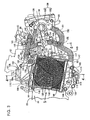
Fig. 7 shows a shroud and the radiator viewed along a line 7-7 inFig. 4 . -
Fig. 8 is a sectional view viewed along a line 8-8 inFig. 3 . - One embodiment shown in
Figs. 1 to 8 of the attached drawings of the invention will be described below. - First as shown in
Fig. 1 , a body frame F of the scooter type motorcycle which is a small-sized vehicle is provided with: ahead pipe 13 that steerably supports a front fork 11 that journals a front wheel WF at its lower end and straddles the front wheel WF and asteering handlebar 12 coupled to an upper end of the front fork 11; a cylindrical main pipe 14 extended backward and downward from thehead pipe 13; a pair of right and leftlower frames 15 connected to a lower part of the main pipe 14 and extended backward; across pipe 16 that connects rear ends of bothlower frames 15; a pair of right and left rear frame pipes 17 each front end of which is linked to each of both ends of thecross pipe 16; andupper frames 18 each of which couples an intermediate part of the main pipe 14 and each intermediate part of both rear frame pipes 17 on the upsides of bothlower frames 15. - The
lower frames 15 are connected to both right and left sides of the lower part of the main pipe 14 by welding, are extended on both sides, further are bent on the rear sides, and are extended backward. Each rear end of thelower frames 15 is connected to each of both right and left ends of thecross pipe 16 by welding. - The power unit P including a water-cooled single-cylinder engine E arranged on the front side of a rear wheel WR and a transmission M arranged on the left side of the rear wheel WR is supported vertically rockably by each front of both rear frame pipes 17 of the body frame F and the rear wheel WR is journalled to the rear of the power unit P.
- The transmission M is linked to a
crank case 21 of the engine E, and is housed in atransmission case 22 extended to the left side of the rear wheel WR. Arear cushion unit 23 is provided between the rear of thetransmission case 22 and the left rear frame pipe 17 out of the pair of right and left rear frame pipes 17. - A goods housing 24 that can house a helmet and others is arranged from the upside of the engine E to the front side of the engine E between both rear frame pipes 17 and between both
upper frames 18 and the rear of thegoods housing 24 is covered with aseat 25 arranged at the back of thehead pipe 13 from the upside. Afuel tank 26 covered with the rear of theseat 25 from the upside is arranged between the rears of both rear frame pipes 17 at the back of thegoods housing 24, and the goods housing 24 and thefuel tank 26 are supported by the body frame F. - A part of the engine E, the body frame F, the goods housing 24 and the
fuel tank 26 are covered with abody cover 29, and a pair of right andleft step floors 27 for putting feet of a rider seated on theseat 25 and a floor tunnel 28 rising upward between bothstep floors 27 are formed inside thebody cover 29. - The floor tunnel 28 includes: a tunnel main part 30 which is supported by the pair of right and left
upper frames 18, which ranges to each inner end of bothstep floors 27, which rises upward and a part of an upper part of which is open; and a cover 31 that openably closes an opening of the upper part of the tunnel main part 30. The front of thegoods housing 24 is housed in the floor tunnel 28. - A hinge mechanism (not shown) for openably supporting the
seat 25 is provided between the front of theseat 25 and the main pipe 14, theseat 25 can be turned forward and diagonally upward so as to enable housing and extracting goods such as a helmet in/from thegoods housing 24, and the cover 31 is turned together with theseat 25 so as to open the upside of the front of the goods housing 24. - As shown in
Figs. 2 and3 , themain unit 33 of the engine E is provided with: acrankcase 21 that rotatably supports acrankshaft 34 having an axis extending in a direction of the width of the body frame F; acylinder block 36 having acylinder bore 35 and connected to thecrankcase 21; acylinder head 37 connected to thecylinder block 36; and ahead cover 38 connected to thecylinder head 37, and as to thecrankcase 21, aleft case half 39 and aright case half 40 are connected on faces perpendicular to the axis of thecrankshaft 34. - The above-mentioned engine
main unit 33 is mounted on the body frame F in a substantially longitudinal direction of the body frame F so that the front of an axis of thecylinder bore 35 is slightly higher and a pair of right andleft brackets 41 provided to an upper part on the rear side of thecrankcase 21 are rockably supported bystays 42 provided to each intermediate part of the rear frame pipes 17 of the body frame F via a supportingshaft 43 and eachmount rubber 44. - A
piston 48 slidably fitted inside thecylinder bore 35 is linked with thecrankshaft 34 via a connectingrod 49. Acamshaft 50 is rotatably supported by thecylinder head 37, and an intake valve and an exhaust valve (respectively not shown) provided to thecylinder head 37 are opened and closed by thecamshaft 50. Atiming chain 52 is housed in achain passage 51 provided to theright case half 40 of thecrankcase 21, thecylinder block 36 and thecylinder head 37, and thetiming chain 52 is wound onto a drivingsprocket 53 provided to thecrankshaft 34 and onto a drivensprocket 54 provided to thecamshaft 50. Hereby, the torque of thecrankshaft 34 is transmitted to thecamshaft 50 at speed reducing ratio of 1/2. - A downstream end of an
intake pipe 55 curved backward from thecylinder head 37 is connected to a side wall of an upper part of thecylinder head 37 and afuel injection valve 56 is attached to theintake pipe 55. An upstream end of theintake pipe 55 is connected to athrottle body 57 arranged on the upside of the enginemain unit 33 and thethrottle body 57 is connected to an air cleaner 58 (seeFig. 1 ) arranged on the upside of thetransmission case 22. - As shown in
Fig. 2 , thetransmission case 22 is configured by a casemain body 61 integrated with theleft case half 39 of thecrankcase 21 and extended backward, aleft cover 62 connected to the casemain body 61 from the left, and aright cover 63 fastened to the rear of the casemain body 61 from the right. - The transmission M is configured by a belt type continuously
variable transmission 64 that continuously shifts the torque of thecrankshaft 34 and a speed reducinggear train 66 provided between anaxle 65 of the rear wheel WR and the belt type continuouslyvariable transmission 64. The belt type continuouslyvariable transmission 64 is housed in atransmission chamber 67 formed between the casemain body 61 and theleft cover 62 in thetransmission case 22 and the speed reducinggear train 66 is housed in agear chamber 68 formed between the casemain body 61 and theright cover 63 in thetransmission case 22. - The belt type continuously
variable transmission 64 is provided with adriving pulley 70 provided to a left end of thecrankshaft 34 in thetransmission chamber 67, a drivenpulley 71 arranged in the rear of thetransmission chamber 67 and anendless V belt 72 wound onto thedriving pulley 70 and onto the drivenpulley 71. - The driving
pulley 70 is provided with apulley half 73 on the fixed side fixed to thecrankshaft 34 and apulley half 74 on the movable side that can approach and can be separated from thepulley half 73 on the fixed side and thepulley half 74 on the movable side is pressed in a direction in which the pulley half on the movable side approaches thepulley half 73 on the fixed side by acentrifugal weight 75 moved on the outside in a radial direction as the number of revolutions of thecrankshaft 34 increases. - An
output shaft 76 having a parallel axis to thecrankshaft 34 is rotatably supported by the casemain body 61 and theright cover 63 in the rear of thetransmission case 22, the drivenpulley 71 is provided with apulley half 77 on the fixed side supported relatively rotatably by theoutput shaft 76 and apulley half 78 on the movable side that can approach and can be separated from thepulley half 77 on the fixed side, and thepulley half 78 on the movable side is pressed toward thepulley half 77 on the fixed side by aspring 79. Aclutch 80 for starting is provided between thepulley half 77 on the fixed side and theoutput shaft 76. - The
output shaft 76, anintermediate shaft 81 parallel to theoutput shaft 76 and theaxle 65 are rotatably supported by the rear of the casemain body 61 and theright cover 63 in thetransmission case 22, the speed reducinggear train 66 is provided between theoutput shaft 76 and theaxle 65 via theintermediate shaft 81, and the rear wheel WR is provided to a right end of theaxle 65 protruded on the right side piercing theright cover 63. - Therefore, the torque of the
crankshaft 34 is transmitted to thedriving pulley 70 and is transmitted from thedriving pulley 70 to the rear wheel WR via theV belt 72, the drivenpulley 71, theclutch 80 for starting and the speed reducinggear train 66. - When the engine E is driven at low speed, centrifugal force that acts on the
centrifugal weight 75 of thedriving pulley 70 is small, therefore, groove width between thepulley half 77 on the fixed side and thepulley half 78 on the movable side is reduced by thespring 79 of the drivenpulley 71, and the gear ratio is at a low level. When the number of revolutions of thecrankshaft 34 is increased from this condition, centrifugal force that acts on thecentrifugal weight 75 increases, groove width between thepulley half 73 on the fixed side and thepulley half 74 on the movable side respectively of thedriving pulley 70 decreases, and as the groove width between thepulley half 77 on the fixed side and thepulley half 78 on the movable side respectively of the drivenpulley 71 is accordingly increased, the gear ratio continuously changes from the low level to a top level. - A
kick shaft 83 having a parallel axis to thecrankshaft 34 is rotatably supported by the casemain body 61 and aleft cover 62 in an intermediate part in a longitudinal direction of thetransmission case 22 and akick pedal 84 is fixed to an end protruded from theleft cover 62 of thekick shaft 83. In addition, areturn spring 85 is provided between thekick shaft 83 and the casemain body 61. - In the meantime, a
fitting member 87 coaxially opposite to a fittedmember 86 provided to the end of thecrankshaft 34 is supported by theleft cover 62 of thetransmission case 22 so that the fitting member can be rotated coaxially with thecrankshaft 34 and can be moved in an axial direction of the crankshaft, and a speed increasinggear train 88 is provided between thekick shaft 83 and thefitting member 87. The rotation of thekick shaft 83 is increased by the speed increasinggear train 88 according to stepping on thekick pedal 84 and is transmitted to thefitting member 87, thefitting member 87 is forward rotated until it is fitted to the fittedmember 86, and thereby, rotating motive power for starting is transmitted to thecrankshaft 34. - Plural vanes 89 for taking cooling air in the
transmission chamber 67 by the rotation of thepulley half 73 on the fixed side are fixed to an outside face of thepulley half 73 on the fixed side of the drivingpulley 70 and an outsideair intake duct 90 for taking cooling air in thetransmission chamber 67 from the outside by the rotation of the vanes 89 together with thepulley half 73 on the fixed side is attached to the front of theleft cover 62 of thetransmission case 22. Areed valve 91 for taking air for ventilation in thecrankcase 21 is attached to the left side of thecylinder block 36 in the enginemain unit 33. - Also referring to
Fig. 4 , arotor 93 is fixed to a right end of thecrankshaft 34 and astator 94 forming agenerator 95 together with therotor 93 is fixed to theright case half 40 of thecrankcase 21 with the stator surrounded by therotor 93. Aradiator 96 is arranged on the side of thecrankcase 21 outside thegenerator 95 and a coolingfan 97 that sucks cooling wind for the cooling wind to pass theradiator 96 is attached to the right end of thecrankshaft 34 with thegenerator 95 held between the cooling fan and theright case half 40 of thecrankcase 21. - Further, also referring to
Fig. 5 , a cylindrical supportingcase 40a surrounding thegenerator 95 from the side is integrated with theright case half 40, ashroud 98 for covering the coolingfan 97 from the side is provided between theradiator 96 and the supportingcase 40a, and theradiator 96 is covered with aradiator cover 99 made of synthetic resin from the outside. - The
radiator 96 is formed by coupling anupper tank 100 and alower tank 101 via acooling core 102 and is attached to theright case half 40 of thecrankcase 21 provided to the enginemain unit 33. That is, a single supportingboss 103 arranged corresponding to the rear of theupper tank 100 and a pair of supportingbosses 104 arranged corresponding to the front and the rear of thelower tank 101 are provided to theright case half 40, theupper tank 100 is fastened to the supportingboss 103 by abolt 105, and thelower tank 101 is fastened to the supportingbosses 104 bybolts 106. - At least a part of the
radiator 96, the front of theupper tank 100 in theradiator 96 in this embodiment is arranged on the downside of the supportingshaft 43, theradiator 96 is arranged on the side of thecrankcase 21 with a front end arranged in front of the supportingshaft 43, an attitude of theradiator 96 in a state in which the radiator is attached to thecrankcase 21 is inclined by an angle α with an axis L of the cylinder bore 35 in thecylinder block 36 of the enginemain unit 33 so that the rear is higher as shown inFig. 3 , and in a state in which the enginemain unit 33 with theradiator 96 is supported by the body frame F via the supportingshaft 43, theradiator 96 is inclined forward by an angle β with a horizontal plane. In addition, the front of theupper tank 100 is formed so that it is lower than the rear to avoid the supportingshaft 43 and the front of theupper tank 100 in theradiator 96 is arranged on the downside of the supportingshaft 43 in a side view. - Also referring to
Figs. 6 and7 , theshroud 98 is integrally provided with: acylindrical part 98a that surrounds the coolingfan 97 from the side; a touchedplate 98b a circumference of which is touched to an inner surface of theradiator 96 and which is linked with one end of thecylindrical part 98a; and a pair ofside plates 98c protruded from the touchedplate 98b with the side plates close and opposite to both sides of theradiator 96 in parts except an upper part of theupper tank 100 and a lower part of thelower tank 101, and is made of synthetic resin. Acircular opening 107 to which the center on the side of an inner surface of acooling core 102 in theradiator 96 is opposite is provided to the substantial center of the touchedplate 98b coaxially with a rotational axis of the coolingfan 97, that is, the axis of thecrankshaft 34, and anexhaust port 108 open downward is provided to a lower part of thecylindrical part 98a. In addition,plural guide projections 109 radially extended from the axis of theopening 107 are protruded at intervals in a circumferential direction of theopening 107 on an inner surface of the touchedpart 98b in a part corresponding to theexhaust port 108. - The
shroud 98 is attached to theradiator 96, each end ofattachment arms cylindrical part 98a of theshroud 98 is attached to each support 110, 111 provided to the front and the rear of theupper tank 100 of theradiator 96 by eachclip 114, and an end of anattachment arm 116 protruded downward from an intermediate part in a longitudinal direction of the touchedplate 98b of theshroud 98 is attached to asupport 115 provided to the downside of an intermediate part in a longitudinal direction of thelower tank 101 of theradiator 96 by aclip 114. - The
radiator cover 99 is attached to theshroud 98 and is fastened to a pair of supportingprojections 117 protruded in positions vertically at an interval of theside plate 98c on the front side out of bothside plates 98c of theshroud 98 and to a supportingprojection 117 protruded from an upper part of theside plate 98c on the rear side by eachscrew 118. - A four-
sided air intake 119 to which an outside face of thecooling core 102 of theradiator 96 is opposite is formed in theradiator cover 99 and alouver 120 arranged in theair intake 119 is provided to theradiator cover 99. - When the cooling
fan 97 is operated, air taken from theair intake 119 passes thecooling core 102 of theradiator 96, cools theradiator 96 and further, is exhausted outside from theexhaust port 108 of theshroud 98. - A
current plate 122 for preventing cooling wind from the coolingfan 97 from flowing on the side of thecrankcase 21 in a part corresponding to theexhaust port 108 is fixed on the side of theright case half 40 of thecrankcase 21 of theexhaust port 108 and the coolingfan 97. Thecurrent plate 122 is attached to theshroud 98 by fastening it to a pair of mountingbosses 123 protruded from a lower part of the touchedplate 98b of theshroud 98 by eachscrew 124 and is formed in the shape of a circular arc along a rotational locus of an outermost end in a radial direction of the coolingfan 97 in a side view. - In addition, the
generator 95 is arranged between the coolingfan 97 and thecrankcase 21, thecurrent plate 122 is arranged outside thegenerator 95, and a turnedpart 122a extended on the side of thecrankcase 21 from its inner end is integrated with thecurrent plate 122. - The
radiator 96 forms a part of a cooling system that enables circulating cooling water in a water jacket 125 (seeFig. 2 ) provided to thecylinder block 36 and thecylinder head 37 of the enginemain unit 33 and the cooling system is provided with: awater pump 126 that supplies cooling water to thewater jacket 125; theradiator 96 interposed between thewater jacket 125 and a suction opening 135 (seeFig. 2 ) of thepump 126; and athermostat 127 arranged in front of theradiator 96 for switching a state in which cooling water from thewater jacket 125 is returned to thewater pump 126 without passing theradiator 96 and a state in which cooling water that passes theradiator 96 from thewater jacket 125 is returned to thewater pump 126 according to the temperature of the cooling water. - A
pump case 128 of thewater pump 126 includes a casemain body 129 fitted and fixed to thecylinder head 37 from its right side and apump cover 130 fastened to the casemain body 129 as shown inFig. 2 and a pump shaft 131 a rotational axis of which is extended in a lateral direction of the body frame F and which is fluid-tight and rotatably supported by the casemain body 129 is coupled to thecamshaft 50 coaxially and so that the pump shaft cannot be relatively rotated. In addition, animpeller 133 is fixed to thepump shaft 131 in apump room 132 formed in thepump case 128. - Also referring to
Fig. 8 , athermostat case 134 housing thethermostat 127 inside is fastened and fixed to thepump cover 130 of thepump case 128 so that the thermostat case is separated in a longitudinal direction (backward in this embodiment) from an axis of thepump shaft 131 and is overlapped with thepump case 128 in the longitudinal direction, and an axis of thethermostat case 134 is inclined so that the axis on the upside is located more outside. - A
water supply pipe 137 extended upward is integrated with the rear of theupper tank 100 of theradiator 96 and acap 138 openable by turning is installed at an upper end of thewater supply pipe 137. Aninlet pipe 139 having an axis extending in the longitudinal direction of the body frame F is provided to an intermediate part of thewater supply pipe 137 at the back of the supportingshaft 43 with the inlet pipe located on the upside of the supportingshaft 43 in a side view. In the meantime, a leading-outpipe 140 for leading out cooling water from an uppermost end of thewater jacket 125 is provided to thecylinder head 37 of the enginemain unit 33 with the leading-out pipe located on the downside of theinlet pipe 139 in a side view, the leading-outpipe 140 and theinlet pipe 139 are coupled via afirst conduit 141 which is a rubber hose, thefirst conduit 141 is extended to be higher from the leading-outpipe 140 toward theinlet pipe 139, and is laid so that the first conduit passes the upside of the supportingshaft 43 in a side view. - A flat reinforcing
plate 142 is provided between the front of theupper tank 100 and theinlet pipe 139, and acircular opening 143 into which the supportingshaft 43 can be inserted is provided to the reinforcingplate 142 with one end of the supportingshaft 43 opposite in a side view in a state in which the enginemain unit 33 is supported by the body frame F via the supportingshaft 43. - A branch connecting pipe 144 is provided to an intermediate part of the leading-out
pipe 140. In the meantime, a water jacket-side connecting pipe 145 is protruded inward and diagonally upward from an upper part of thethermostat case 134 the axis of which is inclined so that the axis on the upside is located more outside, and the branch connecting pipe 144 and the water jacket-side connecting pipe 145 are coupled via asecond conduit 146 such as a rubber hose for leading cooling water from thewater jacket 125 to the side of thethermostat 127. - An
outlet pipe 147 is protruded forward from the lower part of thelower tank 101 of theradiator 96 and a radiator-side connecting pipe 148 is protruded outward and diagonally downward from a lower part of thethermostat case 134. Theoutlet pipe 147 and the radiator-side connecting pipe 148 are coupled via athird conduit 149 such as a rubber hose for leading cooling water from theradiator 96. - One end of a
fourth conduit 150 such as a rubber hose for leading cooling water from thewater pump 126 is connected to adischarge pipe 151 provided to thepump case 128 and the other end of thefourth conduit 150 is connected to aninlet pipe 152 provided to thecylinder block 36 so that the other end communicates with a lower part of thewater jacket 125. - A conduit for air bleeding 153 for bleeding air from an upper part of the
pump room 132 in thepump case 128 is connected to an upper part of thepump case 128. - Further, a connecting
pipe 154 for connecting a rubber hose is provided to thewater supply pipe 137 and is connected to a reservoir (not shown) open to the atmosphere and arranged separately from theradiator 96. When cooling water in theradiator 96 is turned high temperature and is expanded, extra cooling water flows into the reservoir and when the cooling water in theradiator 96 is turned low temperature, the cooling water is returned from the reservoir into theradiator 96. Air accumulated in thewater supply pipe 137 is exhausted into the reservoir by the above-mentioned flow of cooling water between theradiator 96 and the reservoir. That is, when the engine E is operated, air bleeding from the cooling system is also performed satisfactorily. - In such a cooling system, when the warming up of the engine E is completed, cooling water discharged from the
water pump 126 driven by thecamshaft 50 is supplied to thewater jacket 125 in the enginemain unit 33 through thefourth conduit 150 and after the cooling water cools the engine E while it passes thewater jacket 125, it is supplied to theupper tank 100 of theradiator 96 via thefirst conduit 141. The cooling water the temperature of which lowers while it flows from theupper tank 100 into thelower tank 101 via thecooling core 102 and passes theradiator 96 is returned to thesuction opening 135 of thewater pump 126 via thethird conduit 149 and thethermostat 127. In the meantime, when the engine E is in warming up and the temperature of cooling water is low, thethermostat 127 is operated to circulate the cooling water without passing theradiator 96, the cooling water flows from thewater jacket 125 into thewater pump 126 via thesecond conduit 146 and thethermostat 127 without passing theradiator 96, and the temperature promptly rises. - As shown in
Figs. 3 and5 , aposition regulator 99a that blocks the turning to a released position of thecap 138 is integrated with theradiator cover 99 with the position regulator covering thecap 138. In addition, acutout 155 via which a part of the cap 188 is opposite to the outside is provided to theposition regulator 99a. - Next, to explain the action of this embodiment, the
radiator 96 is arranged on the side of thecrankcase 21, the coolingfan 97 that sucks cooling wind to pass the cooling water in theradiator 96 is attached to one end of thecrankshaft 34 and is arranged inside theradiator 96, theshroud 98 that is provided with theexhaust port 108 in the lower part and covers the coolingfan 97 from the side is provided between theradiator 96 and the supportingcase 40a in theright case half 40 of thecrankcase 21, and thecurrent plate 122 for preventing cooling wind from the coolingfan 97 from flowing on the side of thecrankcase 21 in the part corresponding to theexhaust port 108 is fixed not to the side of theexhaust port 108 and the coolingfan 97 but to the side of thecrankcase 21. - Therefore, as cooling wind sucked by the cooling
fan 97 and passing theradiator 96 is prevented from flowing from the coolingfan 97 to the side of thecrankcase 21 in the vicinity of theexhaust port 108 of theshroud 98 by thecurrent plate 122 and smoothly flows into theexhaust port 108, the cooling efficiency of theradiator 96 can be enhanced. - As the
current plate 122 is attached to theshroud 98 and theshroud 98 to which thecurrent plate 122 is attached can be attached to thecrankcase 21, thecurrent plate 122 never obstructs when the coolingfan 97 is attached to thecrankshaft 34, compared with a case that thecurrent plate 122 is attached to thecrankcase 21 and ease of assembly can be enhanced. - In addition, as the
current plate 122 is formed in the shape of the circular arc along the rotational locus of the outermost end in the radial direction of the coolingfan 97 in the side view, a flow of cooling wind from the coolingfan 97 to the side of thecrankcase 21 can be more effectively blocked. - Further, as the
generator 95 is arranged between the coolingfan 97 and thecrankcase 21 and the turnedpart 122a extended from the inner end of thecurrent plate 122 to the side of thecrankcase 21 is integrated with thecurrent plate 122 arranged outside thegenerator 95, cooling wind can more smoothly flow on the side of theexhaust port 108 without causing turbulence in a small quantity of cooling wind that flows between thegenerator 95 and thecurrent plate 122 by making the turnedpart 122a opposite to the periphery of thegenerator 95. - Besides, the leading-out
pipe 140 provided to thecylinder head 37 of the enginemain unit 33 for leading out cooling water from the uppermost part of thewater jacket 125 of the enginemain unit 33 and theinlet pipe 139 provided to theupper tank 100 of theradiator 96 on the upside of the supportingshaft 43 for rockably supporting the power unit P including the enginemain unit 33 by the body frame F are coupled via thefirst conduit 141 that passes the upside of the supportingshaft 43 in the side view to be higher from the leading-outpipe 140 to the side of theinlet pipe 139. - Therefore, air in the
water jacket 125 is led on the side of theradiator 96 via thefirst conduit 141, no conduit dedicated to air bleeding is required, interference between thefirst conduit 141 and the supportingshaft 43 can be avoided, the number of parts is reduced, and a conduit layout around theradiator 96 can be simplified. - In addition, as the supporting
shaft 43 is arranged at the back of the front end of theradiator 96, the inclination of thefirst conduit 141 is inhibited and the length of thefirst conduit 141 can be reduced. - Besides, as the
opening 143 into which the supportingshaft 43 can be inserted is provided to theradiator 96 with one end of the supportingshaft 43 opposite to the opening in the side view in the state in which the enginemain unit 33 is supported by the body frame F via the supportingshaft 43, theradiator 96 is not required to be arranged in a position that does not obstruct work for inserting the supportingshaft 43 when the enginemain unit 33 to thecrankcase 21 of which theradiator 96 is attached is mounted on the body frame F, theradiator 96 can be arranged in an optimum position, and a degree of freedom in the layout can be enhanced: - Besides, as the
inlet pipe 139 is provided to theupper tank 100 of theradiator 96 with the inlet pipe having an axis extending in the longitudinal direction of the body frame F and located on the upside of the supportingshaft 43 in the side view, an overhang in front of theinlet pipe 139 from theradiator 96 is inhibited and thewhole radiator 96 can be compacted. - Besides, as the
thermostat 127 provided with thethermostat case 134 the axis of which is inclined so that the upside is located more outside is arranged in front of theradiator 96, the water jacket-side connecting pipe 145 for connecting thesecond conduit 146 for leading cooling water from thewater jacket 125 is protruded inward and diagonally upward from the upper part of thethermostat case 134 and the radiator-side connecting pipe 148 for connecting thethird conduit 149 for leading cooling water from theradiator 96 is protruded outward and diagonally downward from the lower part of thethermostat case 134, the space for which thethermostat 127 accounts in the lateral direction of the body frame F is reduced, thethermostat 127 can be compacted, and in addition, the length of thesecond conduit 146 connected to the water jacket-side connecting pipe 145 for leading cooling water from thewater jacket 125 and the length of thethird conduit 149 connected to the radiator-side connecting pipe 148 for leading cooling water from theradiator 96 can be possibly reduced. - The
water pump 126 is attached to the outer side of thecylinder head 37 of the enginemain unit 33 with thepump shaft 131 extended in the lateral direction of the body frame F, as thethermostat case 134 is fixed to thepump case 128 of thewater pump 126 with the thermostat case separated from the axis of thepump shaft 131 in the longitudinal direction and with the thermostat case overlapped with thepump case 128 in the longitudinal direction, theconduits water pump 126 and thethermostat 127 can be laid out compactly in the lateral direction of the body frame F. - The embodiment of the invention has been described above, however, the invention is not limited to the embodiment and various design changes without deviating from the invention disclosed in the scope of the claims are allowed.
- For example, in the embodiment, the case applied to the scooter type motorcycle is described, however, the invention can be also applied to another small-sized vehicle such as a three-wheeled vehicle.
- The invention is directed to enhance cooling efficiency by making cooling wind smoothly flow from a cooling fan to an exhaust port in a radiator for a small-sized vehicle where a radiator is arranged on the side of a crankcase forming a part of an engine main unit provided with a water jacket and mounted on a body frame, the cooling fan that sucks cooling wind to pass the radiator is attached to one end of a crankshaft and is arranged inside the radiator and a shroud having the exhaust port and covering the cooling fan from the side is provided between the radiator and the crankcase.
- A
current plate 122 for obstructing a flow of cooling wind from a coolingfan 97 to the side of acrankcase 21 in a part corresponding to anexhaust port 108 is fixed not on the sides of theexhaust port 108 and the coolingfan 97 but on the side of thecrankcase 21.
Claims (4)
- A radiator for a small-sized vehicle where an engine main unit (33) provided with a water jacket (125) is mounted on a body frame (F), a radiator (96) is arranged on the side of a crankcase (21) forming a part of the engine main unit (33), a cooling fan (97) that sucks cooling wind to pass the radiator (96) is attached to one end of a crankshaft (34) rotatably supported by the crankcase (21) and is arranged inside the radiator (96) and a shroud (98) having an exhaust port (108) and covering the cooling fan (97) from the side is provided between the radiator (96) and the crankcase (21),
wherein a current plate (122) for obstructing a flow of cooling wind from the cooling fan (97) to the side of the crankcase (21) in a part corresponding to the exhaust port (108) is fixed not on the sides of the exhaust port (108) and the cooling fan (97) but on the side of the crankcase (21). - The radiator for the small-sized vehicle according to Claim 1, wherein the current plate (122) is attached to the shroud (98).
- The radiator for the small-sized vehicle according to Claim 1 or 2, wherein the current plate (122) is formed in the shape of a circular arc along a rotational locus of an outermost end in a radial direction of the cooling fan (97) in a side view.
- The radiator for the small-sized vehicle according to any of Claims 1 to 3,
wherein: a generator (95) is arranged between the cooling fan (97) and the crankcase (21); and
a turned part (122a) extended from an inner end of the current plate (122) to the side of the crankcase (21) is integrated with the current plate (122) arranged outside the generator (95).
Applications Claiming Priority (1)
| Application Number | Priority Date | Filing Date | Title |
|---|---|---|---|
| JP2007183272A JP4953951B2 (en) | 2007-07-12 | 2007-07-12 | Radiator device for small vehicles |
Publications (2)
| Publication Number | Publication Date |
|---|---|
| EP2014891A1 true EP2014891A1 (en) | 2009-01-14 |
| EP2014891B1 EP2014891B1 (en) | 2019-04-03 |
Family
ID=39956715
Family Applications (1)
| Application Number | Title | Priority Date | Filing Date |
|---|---|---|---|
| EP08010450.8A Ceased EP2014891B1 (en) | 2007-07-12 | 2008-06-09 | Radiator for small-sized vehicle |
Country Status (3)
| Country | Link |
|---|---|
| EP (1) | EP2014891B1 (en) |
| JP (1) | JP4953951B2 (en) |
| CN (1) | CN101344029B (en) |
Cited By (3)
| Publication number | Priority date | Publication date | Assignee | Title |
|---|---|---|---|---|
| WO2018115132A1 (en) | 2016-12-22 | 2018-06-28 | Piaggio & C. S.P.A | Cooling system of the engine of a motorcycle |
| EP3534041A1 (en) * | 2018-02-28 | 2019-09-04 | Honda Motor Co., Ltd. | Power unit |
| CN113027602A (en) * | 2021-03-24 | 2021-06-25 | 北京北方车辆集团有限公司 | Integrated single-channel heat flow power all-in-one machine |
Families Citing this family (2)
| Publication number | Priority date | Publication date | Assignee | Title |
|---|---|---|---|---|
| JP5189008B2 (en) * | 2009-02-19 | 2013-04-24 | 本田技研工業株式会社 | Crankcase structure of internal combustion engine |
| ITUB20155584A1 (en) * | 2015-11-13 | 2017-05-13 | Piaggio & C Spa | Engine cooling system of a motor vehicle |
Citations (5)
| Publication number | Priority date | Publication date | Assignee | Title |
|---|---|---|---|---|
| US4946482A (en) * | 1986-10-15 | 1990-08-07 | Kawasaki Jukogyo Kabushiki Kaisha | Dust removing apparatus for air cleaner |
| EP0950802A2 (en) * | 1998-04-17 | 1999-10-20 | Honda Giken Kogyo Kabushiki Kaisha | Engine operated working machine |
| EP1020351A2 (en) * | 1999-01-11 | 2000-07-19 | Honda Giken Kogyo Kabushiki Kaisha | Swing-type power unit |
| US20050081803A1 (en) * | 2003-10-17 | 2005-04-21 | Atsuhiro Yoshimatsu | Liquid-cooled, vertical shaft type combustion engine |
| JP2005233012A (en) | 2004-02-17 | 2005-09-02 | Honda Motor Co Ltd | Radiator mounting structure to the internal combustion engine body |
Family Cites Families (3)
| Publication number | Priority date | Publication date | Assignee | Title |
|---|---|---|---|---|
| JPS58142315A (en) * | 1982-02-17 | 1983-08-24 | Nitto Electric Ind Co Ltd | Liquid crystal display device |
| JP4407925B2 (en) * | 2004-07-14 | 2010-02-03 | 本田技研工業株式会社 | Cooling device with cooling fan |
| JP4512025B2 (en) * | 2005-11-09 | 2010-07-28 | 本田技研工業株式会社 | Motorcycle |
-
2007
- 2007-07-12 JP JP2007183272A patent/JP4953951B2/en not_active Expired - Fee Related
-
2008
- 2008-06-09 EP EP08010450.8A patent/EP2014891B1/en not_active Ceased
- 2008-07-10 CN CN2008101361444A patent/CN101344029B/en not_active Expired - Fee Related
Patent Citations (5)
| Publication number | Priority date | Publication date | Assignee | Title |
|---|---|---|---|---|
| US4946482A (en) * | 1986-10-15 | 1990-08-07 | Kawasaki Jukogyo Kabushiki Kaisha | Dust removing apparatus for air cleaner |
| EP0950802A2 (en) * | 1998-04-17 | 1999-10-20 | Honda Giken Kogyo Kabushiki Kaisha | Engine operated working machine |
| EP1020351A2 (en) * | 1999-01-11 | 2000-07-19 | Honda Giken Kogyo Kabushiki Kaisha | Swing-type power unit |
| US20050081803A1 (en) * | 2003-10-17 | 2005-04-21 | Atsuhiro Yoshimatsu | Liquid-cooled, vertical shaft type combustion engine |
| JP2005233012A (en) | 2004-02-17 | 2005-09-02 | Honda Motor Co Ltd | Radiator mounting structure to the internal combustion engine body |
Cited By (4)
| Publication number | Priority date | Publication date | Assignee | Title |
|---|---|---|---|---|
| WO2018115132A1 (en) | 2016-12-22 | 2018-06-28 | Piaggio & C. S.P.A | Cooling system of the engine of a motorcycle |
| EP3534041A1 (en) * | 2018-02-28 | 2019-09-04 | Honda Motor Co., Ltd. | Power unit |
| CN113027602A (en) * | 2021-03-24 | 2021-06-25 | 北京北方车辆集团有限公司 | Integrated single-channel heat flow power all-in-one machine |
| CN113027602B (en) * | 2021-03-24 | 2022-09-30 | 北京北方车辆集团有限公司 | Integrated single-channel heat flow power all-in-one machine |
Also Published As
| Publication number | Publication date |
|---|---|
| JP2009019582A (en) | 2009-01-29 |
| JP4953951B2 (en) | 2012-06-13 |
| CN101344029B (en) | 2011-04-06 |
| EP2014891B1 (en) | 2019-04-03 |
| CN101344029A (en) | 2009-01-14 |
Similar Documents
| Publication | Publication Date | Title |
|---|---|---|
| JP6561771B2 (en) | Saddle riding vehicle | |
| JP5362015B2 (en) | Water-cooled power unit structure | |
| CN101344030B (en) | Engine cooling system for small vehicles | |
| JP5924769B2 (en) | Cooling structure in forced air-cooled engine | |
| JP4812636B2 (en) | Cooling water passage structure for water-cooled internal combustion engine | |
| JP4731498B2 (en) | Radiator for motorcycle | |
| EP2014891B1 (en) | Radiator for small-sized vehicle | |
| JP6601149B2 (en) | Saddle riding vehicle | |
| JP6582870B2 (en) | Saddle riding vehicle | |
| EP2014890B1 (en) | Cooling system of engine for motorcycle | |
| JP2002129960A (en) | Radiator device for vehicles | |
| JP4999582B2 (en) | Transmission case cooling structure for motorcycle power unit | |
| JP6620515B2 (en) | Saddle riding vehicle | |
| JP6610165B2 (en) | Saddle riding vehicle | |
| JP4530928B2 (en) | Radiator device for small vehicles | |
| JP4970171B2 (en) | Blow-by gas ventilation system for vehicles | |
| CN1962350A (en) | two-wheeled motor vehicle | |
| JP6565595B2 (en) | Saddle riding vehicle | |
| CN100484822C (en) | straddle vehicle | |
| JP6582869B2 (en) | Saddle riding vehicle | |
| JP6657776B2 (en) | Saddle-type vehicle | |
| JP6668681B2 (en) | Saddle-type vehicle | |
| JP6657774B2 (en) | Saddle-type vehicle | |
| JP6668680B2 (en) | Saddle-type vehicle | |
| JP6613810B2 (en) | Saddle riding vehicle |
Legal Events
| Date | Code | Title | Description |
|---|---|---|---|
| PUAI | Public reference made under article 153(3) epc to a published international application that has entered the european phase |
Free format text: ORIGINAL CODE: 0009012 |
|
| 17P | Request for examination filed |
Effective date: 20080609 |
|
| AK | Designated contracting states |
Kind code of ref document: A1 Designated state(s): AT BE BG CH CY CZ DE DK EE ES FI FR GB GR HR HU IE IS IT LI LT LU LV MC MT NL NO PL PT RO SE SI SK TR |
|
| AX | Request for extension of the european patent |
Extension state: AL BA MK RS |
|
| 17Q | First examination report despatched |
Effective date: 20090220 |
|
| AKX | Designation fees paid |
Designated state(s): DE ES FR IT |
|
| GRAP | Despatch of communication of intention to grant a patent |
Free format text: ORIGINAL CODE: EPIDOSNIGR1 |
|
| INTG | Intention to grant announced |
Effective date: 20181023 |
|
| GRAS | Grant fee paid |
Free format text: ORIGINAL CODE: EPIDOSNIGR3 |
|
| GRAA | (expected) grant |
Free format text: ORIGINAL CODE: 0009210 |
|
| AK | Designated contracting states |
Kind code of ref document: B1 Designated state(s): DE ES FR IT |
|
| REG | Reference to a national code |
Ref country code: DE Ref legal event code: R096 Ref document number: 602008059567 Country of ref document: DE |
|
| RAP2 | Party data changed (patent owner data changed or rights of a patent transferred) |
Owner name: HONDA MOTOR CO., LTD. |
|
| PG25 | Lapsed in a contracting state [announced via postgrant information from national office to epo] |
Ref country code: ES Free format text: LAPSE BECAUSE OF FAILURE TO SUBMIT A TRANSLATION OF THE DESCRIPTION OR TO PAY THE FEE WITHIN THE PRESCRIBED TIME-LIMIT Effective date: 20190403 |
|
| REG | Reference to a national code |
Ref country code: DE Ref legal event code: R119 Ref document number: 602008059567 Country of ref document: DE |
|
| PLBE | No opposition filed within time limit |
Free format text: ORIGINAL CODE: 0009261 |
|
| STAA | Information on the status of an ep patent application or granted ep patent |
Free format text: STATUS: NO OPPOSITION FILED WITHIN TIME LIMIT |
|
| 26N | No opposition filed |
Effective date: 20200106 |
|
| PG25 | Lapsed in a contracting state [announced via postgrant information from national office to epo] |
Ref country code: DE Free format text: LAPSE BECAUSE OF NON-PAYMENT OF DUE FEES Effective date: 20200101 |
|
| PG25 | Lapsed in a contracting state [announced via postgrant information from national office to epo] |
Ref country code: FR Free format text: LAPSE BECAUSE OF NON-PAYMENT OF DUE FEES Effective date: 20190630 |
|
| PGFP | Annual fee paid to national office [announced via postgrant information from national office to epo] |
Ref country code: IT Payment date: 20210511 Year of fee payment: 14 |
|
| PG25 | Lapsed in a contracting state [announced via postgrant information from national office to epo] |
Ref country code: IT Free format text: LAPSE BECAUSE OF NON-PAYMENT OF DUE FEES Effective date: 20220609 |