EP2014606A1 - Flurförderzeug mit mindestens einer Antenne zum Senden und Empfangen von Daten - Google Patents
Flurförderzeug mit mindestens einer Antenne zum Senden und Empfangen von Daten Download PDFInfo
- Publication number
- EP2014606A1 EP2014606A1 EP08005428A EP08005428A EP2014606A1 EP 2014606 A1 EP2014606 A1 EP 2014606A1 EP 08005428 A EP08005428 A EP 08005428A EP 08005428 A EP08005428 A EP 08005428A EP 2014606 A1 EP2014606 A1 EP 2014606A1
- Authority
- EP
- European Patent Office
- Prior art keywords
- antenna
- truck according
- wires
- truck
- flexible material
- Prior art date
- Legal status (The legal status is an assumption and is not a legal conclusion. Google has not performed a legal analysis and makes no representation as to the accuracy of the status listed.)
- Granted
Links
- 239000000463 material Substances 0.000 claims abstract description 21
- 229920003023 plastic Polymers 0.000 claims abstract description 5
- 239000012780 transparent material Substances 0.000 description 2
- 230000005540 biological transmission Effects 0.000 description 1
- 239000002800 charge carrier Substances 0.000 description 1
- 230000001419 dependent effect Effects 0.000 description 1
- 229910003460 diamond Inorganic materials 0.000 description 1
- 239000010432 diamond Substances 0.000 description 1
- 238000002372 labelling Methods 0.000 description 1
- 239000004033 plastic Substances 0.000 description 1
- 230000035939 shock Effects 0.000 description 1
- 230000000007 visual effect Effects 0.000 description 1
Images

Classifications
-
- H—ELECTRICITY
- H01—ELECTRIC ELEMENTS
- H01Q—ANTENNAS, i.e. RADIO AERIALS
- H01Q19/00—Combinations of primary active antenna elements and units with secondary devices, e.g. with quasi-optical devices, for giving the antenna a desired directional characteristic
- H01Q19/10—Combinations of primary active antenna elements and units with secondary devices, e.g. with quasi-optical devices, for giving the antenna a desired directional characteristic using reflecting surfaces
-
- B—PERFORMING OPERATIONS; TRANSPORTING
- B66—HOISTING; LIFTING; HAULING
- B66F—HOISTING, LIFTING, HAULING OR PUSHING, NOT OTHERWISE PROVIDED FOR, e.g. DEVICES WHICH APPLY A LIFTING OR PUSHING FORCE DIRECTLY TO THE SURFACE OF A LOAD
- B66F9/00—Devices for lifting or lowering bulky or heavy goods for loading or unloading purposes
- B66F9/06—Devices for lifting or lowering bulky or heavy goods for loading or unloading purposes movable, with their loads, on wheels or the like, e.g. fork-lift trucks
- B66F9/075—Constructional features or details
- B66F9/0755—Position control; Position detectors
-
- H—ELECTRICITY
- H01—ELECTRIC ELEMENTS
- H01Q—ANTENNAS, i.e. RADIO AERIALS
- H01Q1/00—Details of, or arrangements associated with, antennas
- H01Q1/27—Adaptation for use in or on movable bodies
- H01Q1/32—Adaptation for use in or on road or rail vehicles
- H01Q1/325—Adaptation for use in or on road or rail vehicles characterised by the location of the antenna on the vehicle
- H01Q1/3283—Adaptation for use in or on road or rail vehicles characterised by the location of the antenna on the vehicle side-mounted antennas, e.g. bumper-mounted, door-mounted
-
- H—ELECTRICITY
- H01—ELECTRIC ELEMENTS
- H01Q—ANTENNAS, i.e. RADIO AERIALS
- H01Q1/00—Details of, or arrangements associated with, antennas
- H01Q1/40—Radiating elements coated with or embedded in protective material
Definitions
- the present invention relates to an industrial truck with at least one antenna for transmitting and receiving data from or to RFID transponders.
- RFID transponders where RFID stands for Radio Frequency Identification Device. Possible areas of use are, for example, the labeling of goods and / or products as well as the marking of storage positions and other special locations in a warehouse.
- an antenna for an RFID transponder which acts as a cuboid plastic housing underneath and / or laterally of the fork carriage is attached.
- Such an antenna can, for example, read out a transponder integrated in the charge carrier.
- a disadvantage of such an antenna has been found, however, that it can be easily damaged in daily use.
- the invention has for its object to provide an industrial truck with an antenna for RFID data that is reliably suitable for permanent use without limiting the visibility or the functionality of the truck.
- the truck according to the invention is equipped with at least one antenna for transmitting and receiving data from or to RFID transponders.
- the antenna consists of a network of wires embedded in a flexible material.
- the particular advantage of such an antenna is that the network of wires in the flexible material has a degree of flexibility and flexibility and thus can not easily be damaged.
- the flexible material is also transparent. This means that if the antenna should be located in the field of view of an operator, a visual obstruction is limited. In particular, this also proves to be advantageous if the antenna due to their mounting position on the truck during operation briefly or permanently should get into the driver's field of vision.
- the wires in the network are linked together to form a wire mesh.
- the dimensions of the wire mesh are matched to the frequency.
- the wire mesh forms a planar antenna, which has improved transmission and reception properties.
- the wire mesh has at least two groups of wires which run transversely to one another.
- a wire mesh may for example have a rectangular shape, a square shape or a diamond shape. Since the wires in the wire mesh do not necessarily have to be straight, there is also the possibility of further geometric configurations of the wire mesh.
- a transmitting and / or receiving unit for the antenna for the proper operation of the antenna.
- this can additionally be embedded in the flexible material and be supplied with data and / or power via leads led out of the flexible material.
- a transparent rubber material is provided as a flexible material.
- a transparent plastic material may be used.
- the antenna is preferably mounted in the front section of the truck near the ground.
- the antenna is attached to the load support.
- the antenna is mounted between the fork arms on the load carrier.
- the attached antenna depends at least partially freely over a lower edge of the load carrier. It is also possible to attach the antenna to the vehicle body.
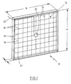
- Fig. 1 shows in a schematic view of an antenna that is specially designed for receiving and sending data to RFID transponders.
- the antenna shown has a substantially rectangular configuration with a width B and a height H.
- the antenna has a depth T.
- the antenna may have a substantially rectangular shape.
- the depth T is significantly smaller than the dimensions in width and height, so that the antenna as a whole still has a high degree of flexibility and can dodge in shocks and touches.
- the antenna body 10 is made of a transparent material having a certain degree of flexibility.
- a transparent material for example, a transparent rubber material into consideration, but also transparent plastic materials can be used.
- the transparent material does not have to ensure complete transparency. Also, to a certain extent clouded transparency can be used in the antenna according to the invention.
- the network 12 used consists of wires.
- the net 12 consists of a first group of approximately parallel wires 14 arranged perpendicular to a second group of parallel wires 16.
- the nodes 18 are the wires conductively connected together.
- the individual wires 14, 16 may consist of interwoven or otherwise connected wire strands.
- the ends of the wires 14 and 16 need not necessarily be formed as free ends. It is also conceivable that the ends of the wires are electrically conductively connected to each other or terminate approximately flush with the corresponding transverse wires.
- a transmitting and receiving unit 20 is provided in the center of the network 12. Via a connecting line 22, the transmitting and receiving unit is connected to additional devices in the periphery.
- the transmitting and receiving unit converts the data to be sent into control commands for the wires of the antenna.
- closer parameters to the antenna used and its wires are preferably stored, so that the processing of the data to the specific antenna can be carried out by the transmitting and receiving unit.
- Fig. 2 shows a schematic view of the front structure of an industrial truck 24. To recognize is schematically the driver's seat 26 with a steering wheel. As a load support means a load fork 28 is provided, which protrudes from a front part of a mast 30. Between the load forks 28, the antenna 32 according to the invention is arranged. The antenna 32 projects partially beyond the lower edge 34 of the mast. The antenna 32 is occasionally referred to as apron antenna due to their arrangement in the front part of the truck. As in Fig. 2 shown only schematically, the antenna is connected via a line 36 to a higher-level control unit, via which the signals for the RFID transponder can be read and evaluated.
Landscapes
- Engineering & Computer Science (AREA)
- Transportation (AREA)
- Structural Engineering (AREA)
- Remote Sensing (AREA)
- Civil Engineering (AREA)
- Life Sciences & Earth Sciences (AREA)
- Geology (AREA)
- Mechanical Engineering (AREA)
- Forklifts And Lifting Vehicles (AREA)
- Details Of Aerials (AREA)
Abstract
Description
- Die vorliegende Erfindung betrifft ein Flurförderzeug mit mindestens einer Antenne zum Senden und Empfangen von Daten von oder an RFID-Transponder.
- Im Bereich der Logistik gibt es zahlreiche Einsatzmöglichkeiten für RFID-Transponder, wobei RFID für Radio Frequency Identification Device steht. Mögliche Einsatzbereiche sind beispielsweise die Kennzeichnung von Waren und/oder Produkten sowie die Kennzeichnung von Lagerpositionen sowie weiteren besonderen Orten in einem Lager.
- Aus
EP 1 710 203 A1 ist eine Antenne für einen RFID-Transponder bekannt, die als ein quaderförmiges Kunststoffgehäuse unterhalb und/oder seitlich des Gabelträgers befestigt ist. Eine solche Antenne kann beispielsweise einen in den Ladungsträger integrierten Transponder auslesen. Als nachteilig an einer solchen Antenne hat sich jedoch herausgestellt, daß diese im täglichen Einsatz leicht beschädigt werden kann. - Der Erfindung liegt die Aufgabe zugrunde, ein Flurförderzeug mit einer Antenne für RFID-Daten bereitzustellen, die ohne Einschränkung der Sicht oder der Funktionalität des Flurförderzeugs zuverlässig für den dauerhaften Einsatz geeignet ist.
- Die erfindungsgemäße Aufgabe wird durch eine Antenne mit den Merkmalen aus Anspruch 1 gelöst. Weitere vorteilhafte Ausgestaltungen bilden den Gegenstand der Unteransprüche.
- Das erfindungsgemäße Flurförderzeug ist mit mindestens einer Antenne zum Senden und Empfangen von Daten von oder an RFID-Transponder ausgestattet. Erfindungsgemäß besteht die Antenne aus einem Netz von Drähten, die in ein flexibles Material eingebettet sind. Der besondere Vorteil einer solchen Antenne besteht darin, daß das Netz von Drähten in dem flexiblen Material ein gewisses Maß an Flexibilität und Biegsamkeit besitzt und so nicht so leicht beschädigt werden kann.
- In einer bevorzugten Ausgestaltung ist das flexible Material zudem transparent ausgebildet. Dies bedeutet, daß wenn die Antenne sich im Sichtfeld einer Bedienperson befinden sollte, eine Sichtbehinderung nur eingeschränkt auftritt. Insbesondere erweist sich dies auch als vorteilhaft, wenn die Antenne aufgrund ihrer Montageposition am Flurförderzeug während des Betriebs kurzzeitig oder dauerhaft in das Blickfeld des Fahrers geraten sollte.
- In einer bevorzugten Ausgestaltung sind die Drähte in dem Netz zu einem Drahtgeflecht miteinander verknüpft. Je nach Frequenz, auf der Daten mit der Antenne gesendet und empfangen werden, sind die Dimensionen des Drahtgeflechts auf die Frequenz abgestimmt. Insgesamt bildet das Drahtgeflecht eine flächige Antenne, die über verbesserte Sende- und Empfangseigenschaften verfügt.
- In einer bevorzugten Weiterbildung weist das Drahtgeflecht mindestens zwei Gruppen von Drähten auf, die quer zueinander verlaufen. Ein solches Drahtgeflecht kann beispielsweise eine Rechteckform, eine quadratische Form oder eine Rautenform besitzen. Da die Drähte in dem Drahtgeflecht nicht unbedingt gradlinig verlaufen müssen, besteht auch die Möglichkeit zu weiteren geometrischen Ausgestaltungen des Drahtgeflechts.
- Für den ordnungsgemäßen Betrieb der Antenne ist in der Regel eine Sende-und/oder Empfangseinheit für die Antenne vorgesehen. Bevorzugt kann diese zusätzlich mit in das flexible Material eingebettet sein und über aus dem flexiblen Material herausgeführte Leitungen mit Daten und/oder Leistung versorgt werden.
- Zweckmäßigerweise ist als flexibles Material ein transparentes Gummimaterial vorgesehen. Alternativ dazu kann auch ein transparentes Kunststoffmaterial eingesetzt werden.
- Die Antenne ist bevorzugt im vorderen Abschnitt des Flurförderzeugs in Bodennähe angebracht. Bevorzugt ist die Antenne am Lasttragmittel befestigt.
- In einer bevorzugten Ausgestaltung ist die Antenne zwischen den Gabelarmen am Lastträger angebracht. Zweckmäßigerweise hängt die angebrachte Antenne mindestens teilweise frei über eine Unterkante des Lastträgers. Auch ist es möglich, die Antenne an dem Fahrzeugkörper anzubringen.
- Ein bevorzugtes Ausführungsbeispiel wird nachfolgend näher erläutert.
- Es zeigt:
- Fig. 1
- eine vergrößerte Ansicht der Antenne, und
- Fig. 2
- die am Flurförderzeug angebrachte Antenne.
-
Fig. 1 zeigt in einer schematischen Ansicht eine Antenne, die speziell zum Empfangen und Senden von Daten an RFID-Transponder ausgebildet ist. Die dargestellte Antenne besitzt eine im wesentlichen rechteckige Ausgestaltung mit einer Breite B und einer Höhe H. Wie in der perspektivischen Darstellung ebenfalls zu erkennen ist, besitzt die Antenne eine Tiefe T. Die Antenne kann eine im wesentlichen rechteckige Form besitzen. Allgemein ist die Tiefe T deutlich geringer als die Abmessungen in Breite und Höhe, so daß die Antenne insgesamt noch ein hohes Maß an Flexibilität besitzt und bei Stößen und Berührungen ausweichen kann. - Der Antennenkörper 10 besteht aus einem transparenten Material, das einen gewissen Grad an Flexibilität besitzt. Als Material kommt beispielsweise ein transparentes Gummimaterial in Betracht, aber auch transparente Kunststoffmaterialien können eingesetzt werden. Das transparente Material muß keine vollständige Durchsicht gewährleisten. Auch eine bis zu einem gewissen Grad eingetrübte Transparenz kann bei der erfindungsgemäßen Antenne eingesetzt werden.
- In
Fig. 1 ist zu erkennen, daß das verwendete Netz 12 aus Drähten besteht. In dem dargestellten Beispiel besteht das Netz 12 aus einer ersten Gruppe von annähernd parallel verlaufenden Drähten 14, die senkrecht zu einer zweiten Gruppe von parallel verlaufenden Drähten 16 angeordnet sind. In den Knotenpunkten 18 sind die Drähte leitend miteinander verbunden. Um für das Netz 12 aus Drähten 14 bzw. 16 eine ausreichende Flexibilität sicherzustellen, können die einzelnen Drähte 14, 16 aus miteinander verwobenen oder sonstwie verbundenen Drahtlitzen bestehen. - Anders als in
Fig. 1 dargestellt, müssen die Enden der Drähte 14 und 16 nicht notwendig als freie Enden ausgebildet sein. Es ist auch denkbar, daß die Enden der Drähte miteinander elektrisch leitend verbunden sind oder ungefähr bündig mit den entsprechend querlaufenden Drähten abschließen. - Im Zentrum des Netzes 12 ist eine Sende- und Empfangseinheit 20 vorgesehen. Über eine Verbindungsleitung 22 ist die Sende- und Empfangseinheit mit zusätzlichen Geräten in der Peripherie verbunden. Die Sende- und Empfangseinheit setzt die zu sendenden Daten in Steuerbefehle für die Drähte der Antenne um. Bevorzugt sind in der Sende- und Empfangseinheit nähere Parameter zu der verwendeten Antenne und deren Drähte abgelegt, so daß die Aufarbeitung der Daten an die konkrete Antenne durch die Sende- und Empfangseinheit erfolgen kann.
-
Fig. 2 zeigt in einer schematischen Ansicht den vorderen Aufbau eines Flurförderzeugs 24. Zu erkennen ist schematisch der Fahrerplatz 26 mit einem Lenkrad. Als Lasttragmittel ist eine Lastgabel 28 vorgesehen, die aus einem vorderen Teil eines Hubgerüsts 30 vorsteht. Zwischen den Lastgabeln 28 ist die erfindungsgemäße Antenne 32 angeordnet. Die Antenne 32 steht teilweise über die Unterkante 34 des Hubgerüsts vor. Die Antenne 32 wird aufgrund ihrer Anordnung im vorderen Teil des Flurförderzeugs gelegentlich auch als Schürzenantenne bezeichnet. Wie inFig. 2 lediglich schematisch dargestellt, wird die Antenne über eine Leitung 36 mit einer übergeordneten Steuereinheit verbunden, über die die Signale für die RFID-Transponder gelesen und ausgewertet werden können.
Claims (11)
- Flurförderzeug mit mindestens einer Antenne zum Senden und Empfangen von Daten von und/oder an RFID-Transponder, dadurch gekennzeichnet, daß die Antenne ein Netz (12) aus Drähten (14, 16) aufweist, die in ein flexibles Material (10) eingebettet sind.
- Flurförderzeug nach Anspruch 1, dadurch gekennzeichnet, daß das flexible Material (10) transparent ausgebildet ist.
- Flurförderzeug nach Anspruch 1 oder 2, dadurch gekennzeichnet, daß die Drähte in dem Netz (12) zu einem Drahtgeflecht miteinander verknüpft sind.
- Flurförderzeug nach Anspruch 3, dadurch gekennzeichnet, daß das Drahtgeflecht mindestens zwei Gruppen (19, 21) von Drähten aufweist, die quer zueinander verlaufen.
- Flurförderzeug nach einem der Ansprüche 1 bis 4, dadurch gekennzeichnet, daß eine Empfangs- und/oder Sendeeinheit (20) für die Antenne in das flexible Material zusätzlich eingebettet ist.
- Flurförderzeug nach einem der Ansprüche 1 bis 5, dadurch gekennzeichnet, daß als flexibles Material ein transparentes Gummimaterial vorgesehen ist.
- Flurförderzeug nach einem der Ansprüche 1 bis 5, dadurch gekennzeichnet, daß als flexibles Material ein transparentes Kunststoffmaterial vorgesehen ist.
- Flurförderzeug nach einem der Ansprüche 1 bis 7, dadurch gekennzeichnet, daß die Antenne (32) im vorderen Abschnitt des Flurförderzeugs in Bodennähe angebracht ist.
- Flurförderzeug nach einem der Ansprüche 1 bis 8, dadurch gekennzeichnet, daß die Antenne (32) an einem Lasttragmittel angebracht ist.
- Flurförderzeug nach einem der Ansprüche 1 bis 9, dadurch gekennzeichnet, daß die Antenne (32) zwischen den Gabelarmen (28) am Lastträger (30) angebracht ist.
- Flurförderzeug nach Anspruch 10, dadurch gekennzeichnet, daß die Antenne (32) mindestens teilweise frei über den Lastträger (30) vorsteht.
Applications Claiming Priority (1)
| Application Number | Priority Date | Filing Date | Title |
|---|---|---|---|
| DE102007032191A DE102007032191A1 (de) | 2007-07-11 | 2007-07-11 | Flurförderzeug mit mindestens einer Antenne zum Senden und Empfangen von Daten |
Publications (2)
| Publication Number | Publication Date |
|---|---|
| EP2014606A1 true EP2014606A1 (de) | 2009-01-14 |
| EP2014606B1 EP2014606B1 (de) | 2010-02-10 |
Family
ID=39711051
Family Applications (1)
| Application Number | Title | Priority Date | Filing Date |
|---|---|---|---|
| EP08005428A Ceased EP2014606B1 (de) | 2007-07-11 | 2008-03-22 | Flurförderzeug mit mindestens einer Antenne zum Senden und Empfangen von Daten |
Country Status (3)
| Country | Link |
|---|---|
| US (1) | US7800548B2 (de) |
| EP (1) | EP2014606B1 (de) |
| DE (2) | DE102007032191A1 (de) |
Cited By (1)
| Publication number | Priority date | Publication date | Assignee | Title |
|---|---|---|---|---|
| US9354070B2 (en) | 2013-10-31 | 2016-05-31 | Crown Equipment Corporation | Systems, methods, and industrial vehicles for determining the visibility of features |
Families Citing this family (4)
| Publication number | Priority date | Publication date | Assignee | Title |
|---|---|---|---|---|
| US8497812B2 (en) * | 2009-01-30 | 2013-07-30 | Raytheon Company | Composite radome and radiator structure |
| EP3866069B1 (de) | 2015-05-06 | 2023-08-02 | Crown Equipment Corporation | Industrielles fahrzeug zur identifizierung defekter sequenzierter etiketten und etikettenlayout zur verwendung damit |
| MX368185B (es) | 2015-05-06 | 2019-09-23 | Crown Equip Corp | Etiqueta de diagnóstico de un lector de etiquetas de vehículo industrial. |
| DE102020213995A1 (de) | 2020-11-06 | 2022-05-12 | Volkswagen Aktiengesellschaft | Antennenvorrichtung |
Citations (5)
| Publication number | Priority date | Publication date | Assignee | Title |
|---|---|---|---|---|
| WO2003034360A1 (en) * | 2001-10-13 | 2003-04-24 | Escort Memory Systems | Flexible rfid antenna panel and system |
| WO2003042916A1 (en) * | 2001-11-12 | 2003-05-22 | 3M Innovative Properties Company | Radio frequency identification systems for asset tracking |
| WO2006094102A1 (en) * | 2005-03-01 | 2006-09-08 | International Paper Company | Mounting bracket |
| EP1710203A1 (de) | 2005-04-06 | 2006-10-11 | Still Gmbh | Flurförderzeug mit einem Lastaufnahmemittel |
| US20060255954A1 (en) * | 2005-05-13 | 2006-11-16 | Ems Technologies, Inc. | Radio frequency identification (RFID) system for a forklift |
Family Cites Families (9)
| Publication number | Priority date | Publication date | Assignee | Title |
|---|---|---|---|---|
| US2063531A (en) * | 1935-05-10 | 1936-12-08 | Hugh Bryan | Automobile antenna |
| US2129766A (en) * | 1937-02-19 | 1938-09-13 | Travis J Hoskins | Radio aerial for automobiles |
| US4370658A (en) * | 1981-04-29 | 1983-01-25 | Hill Fred G | Antenna apparatus and method for making same |
| DE19828122A1 (de) * | 1998-06-25 | 1999-12-30 | Fuba Automotive Gmbh | Antennen aus flächigen Elementen |
| US6933891B2 (en) * | 2002-01-29 | 2005-08-23 | Calamp Corp. | High-efficiency transparent microwave antennas |
| US7151979B2 (en) * | 2002-11-26 | 2006-12-19 | International Paper Company | System and method for tracking inventory |
| US20050014429A1 (en) * | 2003-07-16 | 2005-01-20 | Ruediger Tueshaus | Wire mesh panel and method |
| DE202005015095U1 (de) * | 2005-09-24 | 2006-01-19 | Jungheinrich Aktiengesellschaft | System zur Erkennung und Verwaltung von Paletten |
| DE102005046947B4 (de) * | 2005-09-30 | 2008-09-11 | Continental Automotive Gmbh | Leitfähiges Textil, Antenne und Fahrzeugsitz |
-
2007
- 2007-07-11 DE DE102007032191A patent/DE102007032191A1/de not_active Withdrawn
-
2008
- 2008-03-22 EP EP08005428A patent/EP2014606B1/de not_active Ceased
- 2008-03-22 DE DE502008000359T patent/DE502008000359D1/de active Active
- 2008-04-15 US US12/103,450 patent/US7800548B2/en not_active Expired - Fee Related
Patent Citations (5)
| Publication number | Priority date | Publication date | Assignee | Title |
|---|---|---|---|---|
| WO2003034360A1 (en) * | 2001-10-13 | 2003-04-24 | Escort Memory Systems | Flexible rfid antenna panel and system |
| WO2003042916A1 (en) * | 2001-11-12 | 2003-05-22 | 3M Innovative Properties Company | Radio frequency identification systems for asset tracking |
| WO2006094102A1 (en) * | 2005-03-01 | 2006-09-08 | International Paper Company | Mounting bracket |
| EP1710203A1 (de) | 2005-04-06 | 2006-10-11 | Still Gmbh | Flurförderzeug mit einem Lastaufnahmemittel |
| US20060255954A1 (en) * | 2005-05-13 | 2006-11-16 | Ems Technologies, Inc. | Radio frequency identification (RFID) system for a forklift |
Cited By (1)
| Publication number | Priority date | Publication date | Assignee | Title |
|---|---|---|---|---|
| US9354070B2 (en) | 2013-10-31 | 2016-05-31 | Crown Equipment Corporation | Systems, methods, and industrial vehicles for determining the visibility of features |
Also Published As
| Publication number | Publication date |
|---|---|
| DE502008000359D1 (de) | 2010-03-25 |
| EP2014606B1 (de) | 2010-02-10 |
| DE102007032191A1 (de) | 2009-01-15 |
| US7800548B2 (en) | 2010-09-21 |
| US20090015494A1 (en) | 2009-01-15 |
Similar Documents
| Publication | Publication Date | Title |
|---|---|---|
| EP2014606B1 (de) | Flurförderzeug mit mindestens einer Antenne zum Senden und Empfangen von Daten | |
| EP3425570B1 (de) | Rfid-transponder für eine kontaktlose kommunikation mit plastikgehäuse | |
| EP1767471B1 (de) | System zur Erkennung und Verwaltung von Paletten | |
| DE102007059168A1 (de) | Kommunikationsmodul mit Schlitzantenne | |
| EP1710203B1 (de) | Flurförderzeug mit einem Lastaufnahmemittel | |
| DE102011115967A1 (de) | Windschutzscheibe | |
| EP0895212A2 (de) | Rollwagen mit einem Transponder | |
| DE102008050616A1 (de) | Stapelbarer Transportwagen | |
| DE102008024487B4 (de) | Halbleitervorrichtung mit integrierter Spule und Verfahren zu deren Herstellung | |
| EP2281266B1 (de) | Antennenanordnung für eine chipkarte | |
| EP2628646A1 (de) | Aufprallsensorsystem mit zumindest einem Drucksensor | |
| EP2529337B1 (de) | Sicherheitsanhänger, anordnung mit einem sicherheitsanhänger und verfahren zum betreiben eines sicherheitsanhängers | |
| DE202014001474U1 (de) | UHF- RFID- Transponder | |
| WO2012159618A1 (de) | Rfid-transponder mit abgebogener schlitzantenne | |
| DE10107072B4 (de) | Verfahren zur Herstellung einer Chipkarte | |
| EP4065453B1 (de) | Fördervorrichtung, bearbeitungsanlage, verfahren zum fördern und/oder bearbeiten von gegenständen | |
| EP3174741B1 (de) | Antenne für einen empfänger oder sender in einem kraftfahrzeug, insbesondere für ein reifenzustandsüberwachungssystem | |
| DE602005003682T2 (de) | Antenneneinheit | |
| EP4092641B1 (de) | Kofferaufbau für ein nutzfahrzeug und verfahren zur herstellung eines flächenelements für einen solchen kofferaufbau | |
| EP3676108B1 (de) | Mit einem rfid angeordneter fahrzeugreifen | |
| DE10136549A1 (de) | Scheibe mit einem Folien-Heizelement | |
| DE19628803A1 (de) | Transponder | |
| DE19942217A1 (de) | Antennenanordnung | |
| EP4046958A1 (de) | Flurförderzeug mit erfassungseinrichtungen an gabelzinken | |
| EP0672376A2 (de) | Fensterwischer |
Legal Events
| Date | Code | Title | Description |
|---|---|---|---|
| PUAI | Public reference made under article 153(3) epc to a published international application that has entered the european phase |
Free format text: ORIGINAL CODE: 0009012 |
|
| AK | Designated contracting states |
Kind code of ref document: A1 Designated state(s): AT BE BG CH CY CZ DE DK EE ES FI FR GB GR HR HU IE IS IT LI LT LU LV MC MT NL NO PL PT RO SE SI SK TR |
|
| AX | Request for extension of the european patent |
Extension state: AL BA MK RS |
|
| 17P | Request for examination filed |
Effective date: 20090205 |
|
| GRAP | Despatch of communication of intention to grant a patent |
Free format text: ORIGINAL CODE: EPIDOSNIGR1 |
|
| AKX | Designation fees paid |
Designated state(s): DE GB SE |
|
| GRAS | Grant fee paid |
Free format text: ORIGINAL CODE: EPIDOSNIGR3 |
|
| GRAA | (expected) grant |
Free format text: ORIGINAL CODE: 0009210 |
|
| AK | Designated contracting states |
Kind code of ref document: B1 Designated state(s): DE GB SE |
|
| REG | Reference to a national code |
Ref country code: GB Ref legal event code: FG4D Free format text: NOT ENGLISH |
|
| REF | Corresponds to: |
Ref document number: 502008000359 Country of ref document: DE Date of ref document: 20100325 Kind code of ref document: P |
|
| REG | Reference to a national code |
Ref country code: SE Ref legal event code: TRGR |
|
| PLBE | No opposition filed within time limit |
Free format text: ORIGINAL CODE: 0009261 |
|
| STAA | Information on the status of an ep patent application or granted ep patent |
Free format text: STATUS: NO OPPOSITION FILED WITHIN TIME LIMIT |
|
| 26N | No opposition filed |
Effective date: 20101111 |
|
| PGFP | Annual fee paid to national office [announced via postgrant information from national office to epo] |
Ref country code: SE Payment date: 20170324 Year of fee payment: 10 |
|
| PGFP | Annual fee paid to national office [announced via postgrant information from national office to epo] |
Ref country code: GB Payment date: 20170330 Year of fee payment: 10 |
|
| PG25 | Lapsed in a contracting state [announced via postgrant information from national office to epo] |
Ref country code: SE Free format text: LAPSE BECAUSE OF NON-PAYMENT OF DUE FEES Effective date: 20180323 |
|
| GBPC | Gb: european patent ceased through non-payment of renewal fee |
Effective date: 20180322 |
|
| PG25 | Lapsed in a contracting state [announced via postgrant information from national office to epo] |
Ref country code: GB Free format text: LAPSE BECAUSE OF NON-PAYMENT OF DUE FEES Effective date: 20180322 |
|
| PGFP | Annual fee paid to national office [announced via postgrant information from national office to epo] |
Ref country code: DE Payment date: 20200528 Year of fee payment: 13 |
|
| REG | Reference to a national code |
Ref country code: DE Ref legal event code: R119 Ref document number: 502008000359 Country of ref document: DE |
|
| PG25 | Lapsed in a contracting state [announced via postgrant information from national office to epo] |
Ref country code: DE Free format text: LAPSE BECAUSE OF NON-PAYMENT OF DUE FEES Effective date: 20211001 |