EP2014252B1 - Manipulateur et dispositif de manipulation doté de celui-ci - Google Patents
Manipulateur et dispositif de manipulation doté de celui-ci Download PDFInfo
- Publication number
- EP2014252B1 EP2014252B1 EP08010984A EP08010984A EP2014252B1 EP 2014252 B1 EP2014252 B1 EP 2014252B1 EP 08010984 A EP08010984 A EP 08010984A EP 08010984 A EP08010984 A EP 08010984A EP 2014252 B1 EP2014252 B1 EP 2014252B1
- Authority
- EP
- European Patent Office
- Prior art keywords
- rack
- driving
- manipulator
- rod
- removable
- Prior art date
- Legal status (The legal status is an assumption and is not a legal conclusion. Google has not performed a legal analysis and makes no representation as to the accuracy of the status listed.)
- Expired - Fee Related
Links
Images


Classifications
-
- A—HUMAN NECESSITIES
- A61—MEDICAL OR VETERINARY SCIENCE; HYGIENE
- A61B—DIAGNOSIS; SURGERY; IDENTIFICATION
- A61B34/00—Computer-aided surgery; Manipulators or robots specially adapted for use in surgery
- A61B34/70—Manipulators specially adapted for use in surgery
-
- A—HUMAN NECESSITIES
- A61—MEDICAL OR VETERINARY SCIENCE; HYGIENE
- A61B—DIAGNOSIS; SURGERY; IDENTIFICATION
- A61B34/00—Computer-aided surgery; Manipulators or robots specially adapted for use in surgery
- A61B34/70—Manipulators specially adapted for use in surgery
- A61B34/71—Manipulators operated by drive cable mechanisms
-
- A—HUMAN NECESSITIES
- A61—MEDICAL OR VETERINARY SCIENCE; HYGIENE
- A61B—DIAGNOSIS; SURGERY; IDENTIFICATION
- A61B34/00—Computer-aided surgery; Manipulators or robots specially adapted for use in surgery
- A61B34/30—Surgical robots
Definitions
- the present invention relates to a manipulator and a manipulation device using the same, and more particular to a compact manipulator for a medical application and a manipulation device using the same.
- a manipulator as described in the preamble portion of patent claim 1 is known from JP 1 281 883 A .
- a high-frequency end-effecter is bored into a body of a patient while observing an affected part by using a diagnosis apparatus such as an MRI, an ultrasonic scanner, an endoscope or the like, thereby treating the affected part within a body cavity.
- a diagnosis apparatus such as an MRI, an ultrasonic scanner, an endoscope or the like
- JP-2003-534038 A (patent document 1) describes a manipulation device (a medical apparatus) provided with a guide portion accommodating a puncture needle and a driving apparatus of the puncture needle, in which a guide portion is divided into two portions, a puncture needle is friction bonded between the two portions by a driving roller, and a motor is driven in accordance with a remote control, thereby enabling a linear movement sticking a end-effecter from a body surface of a patient.
- JP-09-285989 A describes a multistage telescopic apparatus for obtaining a great linear moving amount while having a small installed space.
- the puncture can be carried out in accordance with a remote control, however, it is hard to correspond to the other treatment than the puncture. Further, since the end-effecter is linearly inserted to the affected portion from the body surface of the patient, there is a case that it is hard to insert while avoiding the other internal organ, blood vessel or the like (hereinafter, refer to as an obstacle) which should not be injured than the affected portion.
- JP 1 281 883 A discloses a manipulator comprising a manipulator shaft portion; a first rod supported so as to be capable of linearly moving with respect to said manipulator shaft portion and driven by a driving force; a first gear rotatably supported to said first rod and moved in accordance with a movement of said first rod; a first rack fixed to said manipulator shaft portion; a second rack supported so as to be capable of linearly moving in the same direction as said first rod with respect to said manipulator shaft portion; and an end-effecter driven by the driving force generated in accordance with a movement of said second rack, wherein said first rack and said second rack are arranged in parallel in such a manner that a cogged surface of said first rack and a cogged surface of said second rack come face to face, and said first gear is pinched between said first rack and said second rack, and is arranged in a state of engaging with each of said first rack and said second rack.
- An object of the present invention is to provide a manipulator which can enlarge a moving range of an end-effecter in a manipulator leading end while being compact, and a manipulation device using the same.
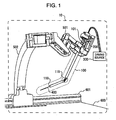
- Fig. 1 is a perspective view of a manipulation device 10 in accordance with the present embodiment.
- the manipulation device 10 is constituted by a manipulator 100, a driving apparatus, a link mechanism 500 and the like, and is structured such as to correspond to various treatments by replacing a plurality of manipulators 100.
- the driving apparatus is constituted by a removable driving mechanism 200, a driving source 300 and the like.
- the manipulator 100 is provided with a manipulator bending portion 119. Accordingly, the manipulator 100 has a freedom avoiding an obstacle.
- the manipulator bending portion 119 is provided in an intermediate portion of the manipulator 100.
- a needle 400 corresponding to a end-effecter is stored in an inner portion of the manipulator 100, from a manipulator leading end portion 118 to the manipulator bending portion 119.
- the needle 400 is arranged so as to be linearly moved by the manipulator 100 and be taken in and out of the manipulator leading end portion 118. Further, the manipulator 100 is connected to the removable driving mechanism 200 via the removable mechanism 101.
- the removable driving mechanism 200 is supported to a rail 601, for example, installed in a bed 600, via a link mechanism 501 and an arm 502.
- a lower end portion of the arm 502 is fixed to the rail 601 so as to be installed.
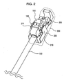
- Fig. 2 shows an enlarged view in the vicinity of the removable mechanism 101.
- the removable mechanism 101 provided in the manipulator 100 is fitted to the removable driving mechanism 200, and the removable mechanism 101 is fixed by a lever 201 of the removable driving mechanism 200. Details of them are mentioned later.
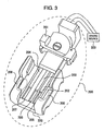
- Fig. 3 is a perspective view of the removable driving mechanism 200.
- the removable driving mechanism 200 is constituted by a base portion 220, a plurality of driving racks, a lever 201 and the like.
- a plurality of driving racks are constituted by a first driving rack 204, a second driving rack 203 and a third driving rack 202.
- the base portion 220 has a plurality of driving rack grooves, left and right guide grooves 208 and 209, and left and right side walls 210 and 211.
- a plurality of driving rack grooves are constituted by a first driving rack groove 207, a second driving rack groove 206 and a third driving rack groove 205.
- the first driving rack groove 207, the second driving rack groove 206 and the third driving rack groove 205 are formed in parallel to each other on an upper surface of a bottom wall of the base portion 220. Further, the first driving rack 204 is movably arranged within the first driving rack groove 207, the second driving rack 203 is arranged within the second driving rack groove 206, and the third driving rack 202 is arranged within the third driving rack groove 205. Each of the driving racks 202 to 204 is independently driven by a driving source 300, and is linearly moved in a groove direction within each of the rack grooves 205 and 207.
- the left and right guide grooves 208 and 209 are provided for guiding the removable mechanism 101 to a predetermined position of the removable driving mechanism 200 at a time of connecting the removable mechanism 101 to the removable driving mechanism 200, and are provided so as to be positioned in both sides of the rack grooves 205 and 207 in the base portion 220 and in the manipulator side.
- the left and right side walls 210 and 211 are provided for fixing the removable mechanism 101 connected to the removable driving mechanism 200, and are attached rotatably to the upper surface of the base portion 200 so as to be positioned in an opposite manipulator side in the base portion 200.
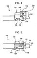
- Fig. 4 is a side elevational view of the removable mechanism 101 provided in the manipulator 100
- Fig. 5 is a bottom elevational view of Fig. 4
- the removable mechanism 101 has a plurality of contact devices, left and right guides 106 and 107, a fixing device 102, a lock cover 145, a lock rack 146 and a lock bar guide 147.
- a plurality of contact devices are constituted by a first contact rack 105, a contact gear 104 and a second contact rack 103.
- the first contact rack 105, the contact gear 104 and the second contact rack 103 are provided in such a manner as to be capable of engaging with the first driving rack 204, the second driving rack 203 and the third driving rack 202 respectively at a time of connecting the removable mechanism 101 to the removable driving mechanism 200.
- the left and right guides 106 and 107 have the same outer surface shapes as inner surface shapes of the left and right guide grooves 208 and 209, and are provided in both sides of the removable mechanism 101.
- the fixing device 102 is attached to a rear end surface of the removable mechanism 101, and is structured such as to be capable of being locked to the lever 201.
- the cylindrical lock bar 145 passes through the lock rack 146 so as to protrude to both sides, and the both side protruding portions are arranged so as to move up and down within the lock bar guide 147.
- the lock rack 146 is arranged so as to be movable up and down in accordance with a vertical motion of the lock bar 145, and a lower surface thereof forms a cogged surface. When the lock rack 146 is moved down, the cogged surface in the lower surface engages with the contact gear 104, and the engagement is canceled at a time when the lock rack 146 is moved up.
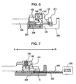
- Fig. 6 is a cross sectional view showing a connected state between the removable mechanism 101 and the removable driving mechanism 200
- Fig. 7 is a cross sectional view showing a connected state between the second driving rack 203 and the contact gear 104
- Fig. 8 is a cross sectional view showing a lock state of the contact gear 104.
- the connection between the removable mechanism 101 and the removable driving mechanism 200 is carried out by inserting the left and right guides 106 and 107 to the left and right guide grooves 208 and 209, rotating the lever 201 in a direction of an arrow in Fig. 3 , and pressing the lever 201 against the fixing device 102 as shown in Fig. 6 .
- the driving force is transmitted from the removable driving mechanism 200 to the manipulator 100 on the basis of an engagement between the first contact rack 105 provided in the removable mechanism 101 and the first driving rack 204, an engagement between the contact gear 104 and the second driving rack 203, and an engagement between the second contact track 103 and the third driving rack 202.
- the contact gear 104 is engaged with the second driving rack 203.
- the second driving rack 203 is connected a driving apparatus side rod 302 having a flexibility.
- the driving apparatus side rod 302 passes through a driving apparatus side tube 305 having a flexibility. It is possible to linearly move the second driving rack 203 in a direction A-B by fixing the driving apparatus side tube 305, and linearly moving the driving apparatus side rod 302 in the direction A-B by the driving source 300.
- the linear motion of the second driving rack 203 is converted into a rotating motion by the contact gear 104.
- the driving apparatus side rod 302 it is possible to avoid a deterioration of a controllability caused by a slack or the like, in comparison with a driving transmission by a wire or the like.
- a fatigue breakage frequently comes into question, however, in the case of the rod, the fatigue breakage is hard to be generated.
- at a time of transmitting the linear motion and the rotating motion at least two wires are generally necessary in the case of the wire, however, in the case of the rod, it is possible to transmit the linear motion by one rod, thereby contributing to a downsizing, an improvement of a maintenance performance and the like.
- the contact gear 104 is unexpectedly rotated from the initial state. Accordingly, in the present embodiment, it is possible to prevent the contact gear 104 from being unexpectedly rotated by fixing the contact gear 104 by moving the lock bar 145 along the lock bar guide 147, and pressing the lock rack 146 against the contact gear 104 as shown in Fig. 8 so as to engage the cogged surface of the lock rack 146 with the cogged surface of the contact gear 104.
- the lock bar 145 comes into contact with the side wall 210 and the side wall 211 as shown in Fig. 2 , and is pushed up along the lock bar guide 147. Accordingly, as shown in Fig. 7 , the lock rack 146 and the contact gear 104 are not engaged with each other, and it is possible to rotate the contact gear 104 by the driving source 300. It is possible to prevent such an accident as to neglect canceling the fixation of the contact rack 104 or the like, by a mechanism by which the lock rack 146 does not automatically engage with the contact gear 104 at a time of attaching.
- the linear moving amounts of the first driving rack 204, the second driving rack 203 and the third driving rack 202 are limited. Accordingly, in the case that a great linear moving amount is necessary in the manipulator 100, it is necessary to amplify the linear moving amount from the removable mechanism 101 of the linear moving manipulator 100 to the manipulator leading end portion 118.
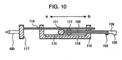
- Fig. 9 is a schematic view of a mechanism amplifying the linear moving amount in the manipulator 100
- Fig. 10 is a cross sectional view of the translational speed enhancement mechanism in Fig. 9 .
- the manipulator bending portion 119 is omitted for simplifying the drawing, in Fig. 9 .
- the first rod 109 connected to the first contact rack 105 is supported to the manipulator shaft portion 110 so as to be linearly movable in the direction A-B.
- the second rod 108 connected to the second contact rack 103 is supported to the manipulator shaft portion 110 so as to be linearly movable in the direction A-B.
- the second rod 108 and the first rod 109 are arranged in parallel.
- the fixed rack (the first rack) 113 is fixed to the manipulator shaft portion 110, and is engaged with the first gear 112.
- the output rack (the third rack) 114 is supported to the manipulator shaft portion 110 so as to be linearly movable in the direction A-B, and is engaged with the second gear 111.
- the first gear 112 is supported to the first rod 109 by its shaft, and is engaged with the transmission rack 115 so as to be rotatable.
- the second gear 111 is supported to the second rod 108 by its shaft, and is engaged with the transmission rack (the second rack) 115 so as to be rotatable.
- the transmission rack 115 is arranged within the transmission rack groove 116 formed in the manipulator shaft portion 110 so as to be long in the direction A-B, and is linearly moved in the direction A-B along the transmission rack shaft 116.
- the first gear 112 is pinched between the fixed rack 113 and the transmission rack 115, and is arranged in a state of being engaged with each of the fixed rack 113 and the transmission rack 115.
- the second gear 111 is pinched between the transmission rack 115 and the output rack 114 as shown in Fig. 10 , and is arranged in a state of being engaged with each of the transmission rack 115 and the output rack 114.
- a handle 117 is fixed to a leading end of the output rack 114 as shown in Fig. 9 , and a needle 400 is attached to the handle 117 in a replaceable manner.
- Fig. 11 is a view explaining a motion of the translational speed enhancement mechanism in Fig. 9 .
- Fig. 11A shows a reference state of the translational speed enhancement mechanism
- Fig. 11B shows a one-stage amplified state of the translational speed enhancement mechanism
- Fig. 11C shows a two-stage amplified state of the translational speed enhancement mechanism, respectively.
- the first rod 109 is linearly moved in the direction B in the state of Fig. 11A , the first gear 112 is moved in the direction B together with the first rod 109 while rotating. Accordingly, the transmission rack 115 engaged with the first gear 112 is exposed to both of a driving force in the direction B caused by the rotation of the first gear 112 and a driving force in the direction B caused by the movement of the first gear 112, and is linearly moved along the transmission rack groove 116 in the direction B at a moving amount which is twice as much as the linear moving amount of the first rod 109. At this time, if the second rod 108 is set to the fixed state, the second gear 111 is rotated on the basis of a linear movement of the transmission rack 115.
- the output rack 114 is linearly moved in the direction A at an equal moving amount to a moving amount of the transmission rack 115. Accordingly, the output rack 114 is linearly moved in a needle point direction at a moving amount which is twice as much as the moving amount of the first rod 109, as shown in Fig. 11B .
- the second gear 111 is moved in the direction A together with the second rod 108 while rotating. Accordingly, the output rack 114 engaging with the second gear 111 is exposed to both the driving force in the direction A caused by the rotation of the second gear 111 and the driving force in the direction A caused by the movement of the second gear 111, and is linearly moved in the direction A at a moving amount which is twice as much as the linear moving amount of the second rod 108, as shown in Fig. 11C .
- the motion mentioned above is explained on the basis of the example in which the second rod 108 is first fixed so as to linearly move the first rod 109, and the first rod 109 is next fixed so as to linearly move the second rod 108, however, the same effect can be obtained even if the moving orders of the second rod 108 and the first rod 109 are inverted. Further, the second rod 108 and the first rod 109 may be simultaneously moved linearly. In this case, it is possible to obtain a large moving amount for a short operating time.
- the translational speed enhancement mechanism is driven by the driving source 300 such as the motor or the like via the removable driving mechanism 200, however, may be driven by a manual driving source.
- the second rod 108 and the first rod 109 may be directly driven by the driving source such as the motor or the like, or manually. In the case of being driven manually, even if a moving amount of a human finger or the like is small, a large linear moving amount can be obtained, and there is an advantage that an operability is good.
- the number of the driving rack provided in the removable driving mechanism 200 is not limited to three including the first driving rack 204, the second driving rack 203 and the third driving rack 202, but may have a necessary number of driving racks required by the manipulator having the maximum degree of freedom in a plurality of replaced manipulators.
- the removable driving mechanism 200 can correspond to various manipulators by unifying the removable mechanism 101 of the replaced manipulator 100.
- the embodiment mentioned above uses two driving racks including the first driving rack 204 and the third driving rack 202, for the mechanism amplifying the linear moving amount, however, it is possible to use one to a plurality of driving racks without being limited to two driving racks.
- the transmission rack 115 is set to a fixed rack fixed to the manipulator shaft portion 110, and only the set of the second gear 111, the output rack 114 and the second rod 108 may be used. At this time, it is possible to linearly move the output rack at the linear moving amount which is twice as much as the linear moving amount of the second rod 108.
- the output rack 114 is set to a new transmission rack, and is connected to a third gear connected to the third rod, and the new output rack is provided in the third gear. At this time, it is possible to linearly move the output rack at a total moving amount obtained by doubling each of the moving amounts of three rods. Further, it is preferable to arrange plural sets of mechanisms each constituted by the transmission rack 115, the second rod 108, the second gear 11 and the output rack 114.
- the mechanism amplifying the linear moving amount in accordance with the present embodiment is constituted by the gear and the rack, and does not use any wire. Accordingly, it is possible to avoid the fatigue disconnection, the slack or the like of the wire, and a maintenance performance is improved. Further, it is possible amplify the linear moving amount regardless of a magnitude of a diameter of the gear.
- the driving force required by one driving mechanism is increased at an equal rate to an amplification factor of the linear moving amount, at a time of outputting a predetermined force.
- the driving force required for linearly moving the output rack into a plurality of driving mechanisms.
- the driving force required by one driving mechanism corresponds to a value obtained by dividing the amplification factor of the linear moving amount by the number of the driving mechanisms.
- the mechanism amplifying the linear moving range in accordance with the present embodiment employs the gears and the racks, however, may employ rollers and plates which come into rolling contact with each other.
- the narrow manipulator which can carry out such a treatment as to insert the end-effecter while avoiding the obstacle within the human body, while having a large moving range of the leading end.
- the manipulation device which can attach and detach the manipulator in the replaceable manner, is structured as a general purpose manner which can be driven by the removable driving mechanism, and can carry out the multifunction treatment with the removable mechanism having both the maintenance performance and the controllability.
Claims (4)
- Manipulateur (100) comprenant :une partie d'arbre de manipulateur (110) ;une première tige (109) supportée de manière à pouvoir se déplacer dans un plan linéaire par rapport à ladite partie d'arbre de manipulateur (110) et à être entraînée par une force motrice ;un premier engrenage (112) supporté de manière rotative par ladite première tige (109) et déplacé en fonction d'un déplacement de ladite première tige (109) ;une première crémaillère (113) fixée à ladite partie d'arbre de manipulateur (110) ;une deuxième crémaillère (115) supportée de manière à pouvoir se déplacer de manière linéaire dans la même direction que ladite première tige (109) par rapport à ladite partie d'arbre de manipulateur (110) ; etun organe terminal actif (400) entraîné par la force motrice générée en fonction d'un déplacement de ladite deuxième crémaillère (115) ;dans lequel ladite première crémaillère (113) et ladite deuxième crémaillère (115) sont disposées en parallèle de sorte qu'une surface dentée de ladite première crémaillère (113) et une surface dentée de ladite deuxième crémaillère (115) se trouvent face à face, et ledit premier engrenage (112) est pincé entre ladite première crémaillère (113) et ladite deuxième crémaillère (115), et est disposé dans un état d'engagement avec ladite première crémaillère (113) et ladite deuxième crémaillère (115),caractérisé en ce que le manipulateur (100) est doté d'une deuxième tige (108) supportée de manière à pouvoir se déplacer dans un plan linéaire par rapport à ladite partie d'arbre de manipulateur (110) et à être entraînée par la force motrice, d'un deuxième engrenage (111) supporté de manière rotative par ladite deuxième tige (108) et d'une troisième crémaillère (114) supportée de manière à pouvoir se déplacer dans un plan linéaire dans la même direction que ladite deuxième tige (108) par rapport à ladite partie d'arbre de manipulateur (110), et en ce que ladite deuxième crémaillère (115) et ladite troisième crémaillère (114) sont disposées en parallèle de sorte qu'une surface dentée de ladite deuxième crémaillère (115) et une surface dentée de ladite troisième crémaillère (114) se trouvent face à face, ledit deuxième engrenage (111) est pincé entre ladite deuxième crémaillère (115) et ladite troisième crémaillère (114), et est disposé dans un état d'engagement avec ladite deuxième crémaillère (115) et ladite troisième crémaillère (114), et ledit organe terminal actif (400) est entraîné par une force motrice générée en fonction du déplacement de ladite troisième crémaillère (114).
- Manipulateur selon la revendication 1,
scaractérisé en ce que plusieurs ensembles de mécanismes sont disposés en ligne, le mécanisme comprenant ladite deuxième crémaillère (115), ladite deuxième tige (108), ledit deuxième engrenage (111) et ladite troisième crémaillère (114). - Dispositif de manipulation (10) comprenant :un manipulateur (100) selon la revendication 1 ; etun appareil d'entraînement entraînant ledit manipulateur (100),caractérisé en ce queladite première tige (109) est entraînée par une force motrice dudit appareil d'entraînement.
- Dispositif de manipulation selon la revendication 3, caractérisé en ce qu'un mécanisme amovible (101) est disposé sur ledit manipulateur (100), un mécanisme d'entraînement amovible (200) est disposé sur ledit appareil d'entraînement, et le mécanisme amovible (101) sur ledit manipulateur (100) peut être détaché par rapport au mécanisme d'entraînement amovible (200) sur ledit appareil d'entraînement.
Applications Claiming Priority (1)
| Application Number | Priority Date | Filing Date | Title |
|---|---|---|---|
| JP2007159875A JP5041361B2 (ja) | 2007-06-18 | 2007-06-18 | マニピュレータおよびこれを用いたマニピュレータ装置 |
Publications (3)
| Publication Number | Publication Date |
|---|---|
| EP2014252A2 EP2014252A2 (fr) | 2009-01-14 |
| EP2014252A3 EP2014252A3 (fr) | 2011-08-24 |
| EP2014252B1 true EP2014252B1 (fr) | 2012-10-10 |
Family
ID=40040114
Family Applications (1)
| Application Number | Title | Priority Date | Filing Date |
|---|---|---|---|
| EP08010984A Expired - Fee Related EP2014252B1 (fr) | 2007-06-18 | 2008-06-17 | Manipulateur et dispositif de manipulation doté de celui-ci |
Country Status (3)
| Country | Link |
|---|---|
| US (1) | US8758327B2 (fr) |
| EP (1) | EP2014252B1 (fr) |
| JP (1) | JP5041361B2 (fr) |
Families Citing this family (12)
| Publication number | Priority date | Publication date | Assignee | Title |
|---|---|---|---|---|
| DE102010023789A1 (de) * | 2010-06-15 | 2011-12-15 | Eb-Invent Gmbh | Knickarmroboter |
| JP5835906B2 (ja) * | 2010-09-30 | 2015-12-24 | オリンパス株式会社 | 屈曲関節機構並びにその屈曲関節機構を有する術具及びその屈曲関節機構を有するマニピュレータ |
| JP5702256B2 (ja) * | 2011-09-29 | 2015-04-15 | Ntn株式会社 | リンク作動装置 |
| WO2013047414A1 (fr) * | 2011-09-29 | 2013-04-04 | Ntn株式会社 | Dispositif de commande d'articulation |
| RU2481073C1 (ru) * | 2011-12-20 | 2013-05-10 | Юрий Иванович Русанов | Устройство выдвижных элементов зажима и их позиционное расположение внутри сферического корпуса многофункциональной диагностико-хирургической робототехнической системы с возможностью информационно-компьютерного управления им. ю.и. русанова |
| JP6042652B2 (ja) | 2012-07-30 | 2016-12-14 | オリンパス株式会社 | 術具及び医療用マニピュレータ |
| JP5996492B2 (ja) | 2013-07-25 | 2016-09-21 | オリンパス株式会社 | 関節機構および医療機器 |
| DE102013220329A1 (de) * | 2013-10-09 | 2015-04-09 | Deutsches Zentrum für Luft- und Raumfahrt e.V. | Repositionierbares Robotersystem |
| DE102013224753A1 (de) | 2013-12-03 | 2015-06-03 | Richard Wolf Gmbh | Instrument, insbesondere ein medizinisch-endoskopisches Instrument oder Technoskop |
| JP6105024B2 (ja) | 2014-10-28 | 2017-03-29 | Thk株式会社 | ロボットにおける回転駆動機構 |
| WO2016068098A1 (fr) * | 2014-10-28 | 2016-05-06 | Thk株式会社 | Mécanisme d'entraînement en rotation dans des robots |
| CN107877498A (zh) * | 2017-11-09 | 2018-04-06 | 无锡百禾工业机器人有限公司 | 一种四轴机械手 |
Family Cites Families (7)
| Publication number | Priority date | Publication date | Assignee | Title |
|---|---|---|---|---|
| JPH01281883A (ja) * | 1988-04-28 | 1989-11-13 | Toshiba Corp | マニピュレータ装置の差動昇降装置 |
| JPH0642601A (ja) * | 1992-07-22 | 1994-02-18 | Murakoshi Koki:Kk | 逓倍移動装置 |
| JPH09285989A (ja) * | 1996-04-19 | 1997-11-04 | Yamaha Motor Co Ltd | 産業用ロボットの多段式伸縮装置 |
| WO2001074259A1 (fr) | 2000-03-30 | 2001-10-11 | Siemens Aktiengesellschaft | Dispositif medical avec mecanisme d'entrainement pour une aiguille |
| US7766894B2 (en) * | 2001-02-15 | 2010-08-03 | Hansen Medical, Inc. | Coaxial catheter system |
| JP4528136B2 (ja) * | 2005-01-11 | 2010-08-18 | 株式会社日立製作所 | 手術装置 |
| US20120191107A1 (en) * | 2010-09-17 | 2012-07-26 | Tanner Neal A | Systems and methods for positioning an elongate member inside a body |
-
2007
- 2007-06-18 JP JP2007159875A patent/JP5041361B2/ja not_active Expired - Fee Related
-
2008
- 2008-06-17 EP EP08010984A patent/EP2014252B1/fr not_active Expired - Fee Related
- 2008-06-18 US US12/141,199 patent/US8758327B2/en not_active Expired - Fee Related
Also Published As
| Publication number | Publication date |
|---|---|
| EP2014252A2 (fr) | 2009-01-14 |
| JP5041361B2 (ja) | 2012-10-03 |
| US20080310945A1 (en) | 2008-12-18 |
| EP2014252A3 (fr) | 2011-08-24 |
| US8758327B2 (en) | 2014-06-24 |
| JP2008307310A (ja) | 2008-12-25 |
Similar Documents
| Publication | Publication Date | Title |
|---|---|---|
| EP2014252B1 (fr) | Manipulateur et dispositif de manipulation doté de celui-ci | |
| US11642188B2 (en) | Actuator and drive for manipulating a tool | |
| US10213094B2 (en) | Slack correction mechanism, manipulator, and manipulator system | |
| US7103931B2 (en) | Table drive system for medical imaging apparatus | |
| JP6157258B2 (ja) | マニピュレータ及びマニピュレータシステム | |
| US8840627B2 (en) | Device for supporting an elongated body and for the controlled translational movement of the same | |
| CN100531666C (zh) | 内窥镜 | |
| CN101574271B (zh) | 医疗用系统 | |
| EP3103374A1 (fr) | Mécanisme d'ajustement d'équilibre de traction, manipulateur, et système de manipulateur | |
| US20160038239A1 (en) | Medical manipulator | |
| EP1908390A1 (fr) | Endoscope | |
| JP5980764B2 (ja) | 術具 | |
| US20060155262A1 (en) | Surgical operation apparatus and manipulator for use therein | |
| EP1769722A3 (fr) | Système endoscopique avec un endoscope et un instrument médical raccordé à l'endoscope | |
| US20230126521A1 (en) | Endoscope | |
| US20160324589A1 (en) | Surgical-manipulator manipulating device and surgical manipulator system | |
| US20120053417A1 (en) | Endoscope and hardness adjuster | |
| CN105636545A (zh) | 手术器具 | |
| US11504199B2 (en) | Medical manipulator | |
| CN114191079A (zh) | 一种独立驱动式介入手术机器人 | |
| JP2012081010A (ja) | 内視鏡及び硬度調整装置 | |
| US20130079711A1 (en) | Endoscope manipulation adapter | |
| CN217118454U (zh) | 医疗设备的驱动装置及驱动系统 | |
| CN114305592B (zh) | 一种偏摆机构及手术器械 | |
| CN113499018A (zh) | 内镜镜身推送装置及消化内镜机器人 |
Legal Events
| Date | Code | Title | Description |
|---|---|---|---|
| PUAI | Public reference made under article 153(3) epc to a published international application that has entered the european phase |
Free format text: ORIGINAL CODE: 0009012 |
|
| 17P | Request for examination filed |
Effective date: 20080617 |
|
| AK | Designated contracting states |
Kind code of ref document: A2 Designated state(s): AT BE BG CH CY CZ DE DK EE ES FI FR GB GR HR HU IE IS IT LI LT LU LV MC MT NL NO PL PT RO SE SI SK TR |
|
| AX | Request for extension of the european patent |
Extension state: AL BA MK RS |
|
| PUAL | Search report despatched |
Free format text: ORIGINAL CODE: 0009013 |
|
| AK | Designated contracting states |
Kind code of ref document: A3 Designated state(s): AT BE BG CH CY CZ DE DK EE ES FI FR GB GR HR HU IE IS IT LI LT LU LV MC MT NL NO PL PT RO SE SI SK TR |
|
| AX | Request for extension of the european patent |
Extension state: AL BA MK RS |
|
| RIC1 | Information provided on ipc code assigned before grant |
Ipc: A61B 19/00 20060101AFI20110720BHEP |
|
| GRAP | Despatch of communication of intention to grant a patent |
Free format text: ORIGINAL CODE: EPIDOSNIGR1 |
|
| AKX | Designation fees paid |
Designated state(s): DE |
|
| GRAS | Grant fee paid |
Free format text: ORIGINAL CODE: EPIDOSNIGR3 |
|
| GRAA | (expected) grant |
Free format text: ORIGINAL CODE: 0009210 |
|
| AK | Designated contracting states |
Kind code of ref document: B1 Designated state(s): DE |
|
| REG | Reference to a national code |
Ref country code: DE Ref legal event code: R096 Ref document number: 602008019229 Country of ref document: DE Effective date: 20121206 |
|
| PLBE | No opposition filed within time limit |
Free format text: ORIGINAL CODE: 0009261 |
|
| STAA | Information on the status of an ep patent application or granted ep patent |
Free format text: STATUS: NO OPPOSITION FILED WITHIN TIME LIMIT |
|
| 26N | No opposition filed |
Effective date: 20130711 |
|
| REG | Reference to a national code |
Ref country code: DE Ref legal event code: R097 Ref document number: 602008019229 Country of ref document: DE Effective date: 20130711 |
|
| PGFP | Annual fee paid to national office [announced via postgrant information from national office to epo] |
Ref country code: DE Payment date: 20170613 Year of fee payment: 10 |
|
| REG | Reference to a national code |
Ref country code: DE Ref legal event code: R119 Ref document number: 602008019229 Country of ref document: DE |
|
| PG25 | Lapsed in a contracting state [announced via postgrant information from national office to epo] |
Ref country code: DE Free format text: LAPSE BECAUSE OF NON-PAYMENT OF DUE FEES Effective date: 20190101 |