EP2012415A2 - Verfahren zur Steuerung eines DC/DC-Aufwärtswandlers und entsprechender Wandler - Google Patents
Verfahren zur Steuerung eines DC/DC-Aufwärtswandlers und entsprechender Wandler Download PDFInfo
- Publication number
- EP2012415A2 EP2012415A2 EP08104601A EP08104601A EP2012415A2 EP 2012415 A2 EP2012415 A2 EP 2012415A2 EP 08104601 A EP08104601 A EP 08104601A EP 08104601 A EP08104601 A EP 08104601A EP 2012415 A2 EP2012415 A2 EP 2012415A2
- Authority
- EP
- European Patent Office
- Prior art keywords
- comp
- converter
- threshold
- ocp
- comparison flag
- Prior art date
- Legal status (The legal status is an assumption and is not a legal conclusion. Google has not performed a legal analysis and makes no representation as to the accuracy of the status listed.)
- Withdrawn
Links
- 238000000034 method Methods 0.000 title claims description 12
- 238000004146 energy storage Methods 0.000 claims abstract 2
- 238000006243 chemical reaction Methods 0.000 description 1
- 230000003247 decreasing effect Effects 0.000 description 1
- 238000011835 investigation Methods 0.000 description 1
- 238000009738 saturating Methods 0.000 description 1
- 230000003068 static effect Effects 0.000 description 1
Images




Classifications
-
- H—ELECTRICITY
- H02—GENERATION; CONVERSION OR DISTRIBUTION OF ELECTRIC POWER
- H02M—APPARATUS FOR CONVERSION BETWEEN AC AND AC, BETWEEN AC AND DC, OR BETWEEN DC AND DC, AND FOR USE WITH MAINS OR SIMILAR POWER SUPPLY SYSTEMS; CONVERSION OF DC OR AC INPUT POWER INTO SURGE OUTPUT POWER; CONTROL OR REGULATION THEREOF
- H02M3/00—Conversion of DC power input into DC power output
- H02M3/02—Conversion of DC power input into DC power output without intermediate conversion into AC
- H02M3/04—Conversion of DC power input into DC power output without intermediate conversion into AC by static converters
- H02M3/10—Conversion of DC power input into DC power output without intermediate conversion into AC by static converters using discharge tubes with control electrode or semiconductor devices with control electrode
- H02M3/145—Conversion of DC power input into DC power output without intermediate conversion into AC by static converters using discharge tubes with control electrode or semiconductor devices with control electrode using devices of a triode or transistor type requiring continuous application of a control signal
- H02M3/155—Conversion of DC power input into DC power output without intermediate conversion into AC by static converters using discharge tubes with control electrode or semiconductor devices with control electrode using devices of a triode or transistor type requiring continuous application of a control signal using semiconductor devices only
-
- H—ELECTRICITY
- H02—GENERATION; CONVERSION OR DISTRIBUTION OF ELECTRIC POWER
- H02M—APPARATUS FOR CONVERSION BETWEEN AC AND AC, BETWEEN AC AND DC, OR BETWEEN DC AND DC, AND FOR USE WITH MAINS OR SIMILAR POWER SUPPLY SYSTEMS; CONVERSION OF DC OR AC INPUT POWER INTO SURGE OUTPUT POWER; CONTROL OR REGULATION THEREOF
- H02M1/00—Details of apparatus for conversion
- H02M1/14—Arrangements for reducing ripples from DC input or output
- H02M1/15—Arrangements for reducing ripples from DC input or output using active elements
-
- H—ELECTRICITY
- H02—GENERATION; CONVERSION OR DISTRIBUTION OF ELECTRIC POWER
- H02M—APPARATUS FOR CONVERSION BETWEEN AC AND AC, BETWEEN AC AND DC, OR BETWEEN DC AND DC, AND FOR USE WITH MAINS OR SIMILAR POWER SUPPLY SYSTEMS; CONVERSION OF DC OR AC INPUT POWER INTO SURGE OUTPUT POWER; CONTROL OR REGULATION THEREOF
- H02M3/00—Conversion of DC power input into DC power output
- H02M3/02—Conversion of DC power input into DC power output without intermediate conversion into AC
- H02M3/04—Conversion of DC power input into DC power output without intermediate conversion into AC by static converters
- H02M3/10—Conversion of DC power input into DC power output without intermediate conversion into AC by static converters using discharge tubes with control electrode or semiconductor devices with control electrode
- H02M3/145—Conversion of DC power input into DC power output without intermediate conversion into AC by static converters using discharge tubes with control electrode or semiconductor devices with control electrode using devices of a triode or transistor type requiring continuous application of a control signal
- H02M3/155—Conversion of DC power input into DC power output without intermediate conversion into AC by static converters using discharge tubes with control electrode or semiconductor devices with control electrode using devices of a triode or transistor type requiring continuous application of a control signal using semiconductor devices only
- H02M3/156—Conversion of DC power input into DC power output without intermediate conversion into AC by static converters using discharge tubes with control electrode or semiconductor devices with control electrode using devices of a triode or transistor type requiring continuous application of a control signal using semiconductor devices only with automatic control of output voltage or current, e.g. switching regulators
Definitions
- This invention relates in general to voltage converters and more particularly to a method of controlling a step-up DC-DC converter and a related converter.
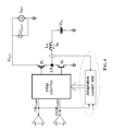
- FIG. 1 depicts a typical functioning scheme of a hysteretic step-up converter.
- the maximum duration of the charge phase T ON and the minimum duration of the discharge phase T OFF are pre-established.
- a feedback voltage FB representative of the output voltage (in the depicted case it is generated by a voltage divider), is compared with a reference value FB REF .
- FB FB REF
- the switch N 1 is turned off and energy stored up to that moment in the inductor is discharged on the load. After the inductor has discharged, the system remains in a stand-by state until FB ⁇ FB REF .
- the control block CONTROL turns the switch N 1 in function of a first comparison flag FB COMP and of a second comparison flag OCP COMP , generated by comparing the voltage LX on the inductor (that is proportional to the current that flows therethrough) with a second reference voltage OCP REF .
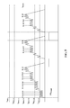
- the current through the inductor is constantly monitored such that during the phase it increases (T ON ) does not overcome a pre-established threshold (proportional to the voltage OCP REF ), such to limit the input current and preventing the inductor from saturating.
- the slope of the current through the inductor is proportional to the supply voltage V IN during the charge phase T ON and to V OUT -V IN during the discharge phase TOFF.
- energy stored in the inductor is proportional to the current, thus as soon as FB ⁇ FB REF , the inductor discharges completely on the output tank capacitance causing a relatively large voltage ripple, and the increase of the peak current through the inductor causes a larger mean square value of the input current, thus causing an abrupt increase of power losses in the power switch, with a consequent reduction of conversion efficiency.
- the value of the maximum current through the inductor is increased stepwise up to attain a maximum pre-established value.
- a relatively low current threshold is thus set in presence of a load that absorbs a relatively small current and a higher current threshold when the load absorbs a relatively large current.
- the output voltage of the converter and the inductor voltage are compared with respective thresholds, thus depending from the result of these distinct comparisons, the ripple of the output voltage of the converter is effectively limited by adjusting the comparison threshold of the inductor voltage.
- the number of occurrences of the output voltage of the converter reaching its respective threshold is down counted and the number of occurrences of the inductor voltage reaching its respective threshold is up-counted: when the resulting count attains a certain value, the comparison threshold of the inductor voltage is incremented and the counting is reset.
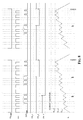
- the comparison threshold of the current through the inductor is adjusted in function of the comparison flags FB COMP and OCP COMP , as schematically depicted in Figure 4 .
- different levels of current limitation are established up to a maximum level I MAX .
- I MAX maximum level
- it is possible to set m 4 uniformly spaced current thresholds.
- the device When again FB ⁇ FB REF , the device will start switching again with a current limitation threshold set at the immediately smaller level than the level of the recorded last current limitation threshold.
- the device adjusts the control to the load being supplied. If the peak current through the inductor is excessively small, is increased for ensuring a sufficient output current or decreased if too large stepwise.
- the advantage is that the peak current through the inductor will be adjusted to the lowest possible value compatible to load conditions. Therefore, the ripple and the switching losses tied to the mean square of the current are reduced.
- the converter of this invention may be realized by adding an external digital counter (UP/DOWN) and few additional switches to a common step-up converter without introducing any static current dissipating circuits. This feature is important for realizing converters with reduced stand-by power consumptions.
- UP/DOWN external digital counter
- the invention is outstandingly effective for controlling the peak current through the inductor in function of the load current, without requiring any complex control loop and external compensation components.
Landscapes
- Engineering & Computer Science (AREA)
- Power Engineering (AREA)
- Dc-Dc Converters (AREA)
Applications Claiming Priority (1)
| Application Number | Priority Date | Filing Date | Title |
|---|---|---|---|
| IT000060A ITVA20070060A1 (it) | 2007-07-04 | 2007-07-04 | Metodo di controllo di un convertitore step-up dc-dc e relativo convertitore |
Publications (2)
| Publication Number | Publication Date |
|---|---|
| EP2012415A2 true EP2012415A2 (de) | 2009-01-07 |
| EP2012415A3 EP2012415A3 (de) | 2010-05-26 |
Family
ID=39863075
Family Applications (1)
| Application Number | Title | Priority Date | Filing Date |
|---|---|---|---|
| EP08104601A Withdrawn EP2012415A3 (de) | 2007-07-04 | 2008-07-02 | Verfahren zur Steuerung eines DC/DC-Aufwärtswandlers und entsprechender Wandler |
Country Status (3)
| Country | Link |
|---|---|
| US (1) | US7868596B2 (de) |
| EP (1) | EP2012415A3 (de) |
| IT (1) | ITVA20070060A1 (de) |
Cited By (2)
| Publication number | Priority date | Publication date | Assignee | Title |
|---|---|---|---|---|
| CN101997410B (zh) * | 2009-08-20 | 2012-10-10 | 立锜科技股份有限公司 | 具有瞬时控制功能的切换式电源电路与其控制电路与方法 |
| CN107306080A (zh) * | 2016-04-19 | 2017-10-31 | 联发科技(新加坡)私人有限公司 | 直流转直流电压转换器及其控制方法 |
Families Citing this family (7)
| Publication number | Priority date | Publication date | Assignee | Title |
|---|---|---|---|---|
| US9099919B2 (en) | 2011-05-09 | 2015-08-04 | The Hong Kong University Of Science And Technology | Single-inductor-multiple-output regulator with synchronized current mode hysteretic control |
| JP2012253953A (ja) * | 2011-06-06 | 2012-12-20 | Mitsumi Electric Co Ltd | 昇圧型dc−dcコンバータ |
| US9048728B2 (en) * | 2012-10-08 | 2015-06-02 | Texas Instruments Incorporated | Switch pairs between resistor network and high/low DC converter comparator input |
| KR101905586B1 (ko) * | 2012-12-21 | 2018-10-10 | 한국전자통신연구원 | 최대 전력 추출 장치 |
| FR3083883B1 (fr) | 2018-07-10 | 2020-06-12 | Continental Automotive France | Procede de controle d'un convertisseur de tension continu-continu |
| US10615694B2 (en) | 2018-09-07 | 2020-04-07 | Dialog Semiconductor (Uk) Limited | Circuit and method for suppressing audio noise in DC-DC converters |
| US10511225B1 (en) | 2018-09-07 | 2019-12-17 | Dialog Semiconductor (Uk) Limited | Low IQ hysteretic-PWM automated hybrid control architecture for a switching converter |
Citations (2)
| Publication number | Priority date | Publication date | Assignee | Title |
|---|---|---|---|---|
| US20060125454A1 (en) | 2004-12-10 | 2006-06-15 | Tien-Tzu Chen | Switching voltage regulator operating without a discontinuous mode |
| US20060158168A1 (en) | 2002-06-07 | 2006-07-20 | Shinichi Yoshida | Switching power supply device and switching power supply system |
Family Cites Families (5)
| Publication number | Priority date | Publication date | Assignee | Title |
|---|---|---|---|---|
| US5481178A (en) * | 1993-03-23 | 1996-01-02 | Linear Technology Corporation | Control circuit and method for maintaining high efficiency over broad current ranges in a switching regulator circuit |
| JP3636321B2 (ja) * | 2002-04-24 | 2005-04-06 | ローム株式会社 | スイッチング電源装置 |
| US6724174B1 (en) * | 2002-09-12 | 2004-04-20 | Linear Technology Corp. | Adjustable minimum peak inductor current level for burst mode in current-mode DC-DC regulators |
| JP4017490B2 (ja) * | 2002-10-02 | 2007-12-05 | 株式会社デンソー | Dc/dcコンバータ |
| US7372238B1 (en) * | 2004-04-29 | 2008-05-13 | National Semiconductor Corporation | Apparatus and method for step-down switching voltage regulation |
-
2007
- 2007-07-04 IT IT000060A patent/ITVA20070060A1/it unknown
-
2008
- 2008-07-02 EP EP08104601A patent/EP2012415A3/de not_active Withdrawn
- 2008-07-03 US US12/167,772 patent/US7868596B2/en active Active
Patent Citations (2)
| Publication number | Priority date | Publication date | Assignee | Title |
|---|---|---|---|---|
| US20060158168A1 (en) | 2002-06-07 | 2006-07-20 | Shinichi Yoshida | Switching power supply device and switching power supply system |
| US20060125454A1 (en) | 2004-12-10 | 2006-06-15 | Tien-Tzu Chen | Switching voltage regulator operating without a discontinuous mode |
Cited By (6)
| Publication number | Priority date | Publication date | Assignee | Title |
|---|---|---|---|---|
| CN101997410B (zh) * | 2009-08-20 | 2012-10-10 | 立锜科技股份有限公司 | 具有瞬时控制功能的切换式电源电路与其控制电路与方法 |
| CN107306080A (zh) * | 2016-04-19 | 2017-10-31 | 联发科技(新加坡)私人有限公司 | 直流转直流电压转换器及其控制方法 |
| EP3240171A1 (de) * | 2016-04-19 | 2017-11-01 | MediaTek Singapore Pte Ltd. | Gleichspannungswandler mit burst-betrieb und dynamisch anpassbarer spitzenstromregelung |
| US10033279B2 (en) | 2016-04-19 | 2018-07-24 | Mediatek Singapore Pte. Ltd. | DC-DC voltage converter and associated control method capable of dynamically adjusting upper boundary of inductor current |
| TWI632764B (zh) * | 2016-04-19 | 2018-08-11 | 新加坡商聯發科技(新加坡)私人有限公司 | 直流轉直流電壓轉換器及其控制方法 |
| CN107306080B (zh) * | 2016-04-19 | 2019-06-28 | 联发科技(新加坡)私人有限公司 | 直流转直流电压转换器及其控制方法 |
Also Published As
| Publication number | Publication date |
|---|---|
| EP2012415A3 (de) | 2010-05-26 |
| US20090015230A1 (en) | 2009-01-15 |
| US7868596B2 (en) | 2011-01-11 |
| ITVA20070060A1 (it) | 2009-01-05 |
Similar Documents
| Publication | Publication Date | Title |
|---|---|---|
| EP2012415A2 (de) | Verfahren zur Steuerung eines DC/DC-Aufwärtswandlers und entsprechender Wandler | |
| US8519691B2 (en) | Current limiting for DC-DC converters | |
| US7957165B2 (en) | DC-DC converter with a plurality of soft-start control circuits | |
| US9515556B2 (en) | Current pulse count control in a voltage regulator | |
| US7714547B2 (en) | Method and apparatus for constant on-time switch mode converters | |
| US8669748B2 (en) | Device for synchronous DC-DC conversion and synchronous DC-DC converter | |
| JP6211916B2 (ja) | スイッチングレギュレータ | |
| JP6161339B2 (ja) | 昇圧型スイッチングレギュレータおよび半導体装置 | |
| US6600300B2 (en) | Digitally controlled DC/DC converter | |
| US9825524B2 (en) | Dynamic control loop for switching regulators | |
| US20120153919A1 (en) | Switching Mode Power Supply Control | |
| US10948934B1 (en) | Voltage regulator with piecewise linear loadlines | |
| US9667144B2 (en) | DC-DC converter with reverse current detecting circuit | |
| US20080101102A1 (en) | Circuits and methods for controlling a converter | |
| US7035071B1 (en) | Current limit with adaptive cycle skipping for switching regulators | |
| US8164319B2 (en) | System and method for adapting clocking pulse widths for DC-to-DC converters | |
| US20240313638A1 (en) | Current limit control circuit for boost converter in ccm | |
| US6922346B2 (en) | System and method to limit maximum duty cycle and/or provide a maximum volt-second clamp | |
| CN222301615U (zh) | 开关模式电源smps和集成电路ic设备 | |
| US8120339B2 (en) | Switching power supply with switching circuits | |
| EP4243261B1 (de) | Modul zur steuerung eines schalt-abwärts-aufwärtswandlers mit überstromerkennung und verfahren zur steuerung eines schalt-abwärts-aufwärtswandlers | |
| US11588408B2 (en) | Power supply circuit, corresponding device and method | |
| JP2010063231A (ja) | スイッチングレギュレータ | |
| KR20210103398A (ko) | 전력 변환기 제어를 위한 온-타임 연장 | |
| JP4871022B2 (ja) | スイッチング電源用制御回路 |
Legal Events
| Date | Code | Title | Description |
|---|---|---|---|
| PUAI | Public reference made under article 153(3) epc to a published international application that has entered the european phase |
Free format text: ORIGINAL CODE: 0009012 |
|
| AK | Designated contracting states |
Kind code of ref document: A2 Designated state(s): AT BE BG CH CY CZ DE DK EE ES FI FR GB GR HR HU IE IS IT LI LT LU LV MC MT NL NO PL PT RO SE SI SK TR |
|
| AX | Request for extension of the european patent |
Extension state: AL BA MK RS |
|
| 17P | Request for examination filed |
Effective date: 20090320 |
|
| RAP1 | Party data changed (applicant data changed or rights of an application transferred) |
Owner name: STMICROELECTRONICS SRL |
|
| PUAL | Search report despatched |
Free format text: ORIGINAL CODE: 0009013 |
|
| AK | Designated contracting states |
Kind code of ref document: A3 Designated state(s): AT BE BG CH CY CZ DE DK EE ES FI FR GB GR HR HU IE IS IT LI LT LU LV MC MT NL NO PL PT RO SE SI SK TR |
|
| AX | Request for extension of the european patent |
Extension state: AL BA MK RS |
|
| AKX | Designation fees paid |
Designated state(s): DE FR GB IT |
|
| RAP1 | Party data changed (applicant data changed or rights of an application transferred) |
Owner name: STMICROELECTRONICS SRL |
|
| STAA | Information on the status of an ep patent application or granted ep patent |
Free format text: STATUS: THE APPLICATION HAS BEEN WITHDRAWN |
|
| 18W | Application withdrawn |
Effective date: 20120702 |