EP2010985B1 - Steuerung für eine bedieneinheit - Google Patents
Steuerung für eine bedieneinheit Download PDFInfo
- Publication number
- EP2010985B1 EP2010985B1 EP07723862A EP07723862A EP2010985B1 EP 2010985 B1 EP2010985 B1 EP 2010985B1 EP 07723862 A EP07723862 A EP 07723862A EP 07723862 A EP07723862 A EP 07723862A EP 2010985 B1 EP2010985 B1 EP 2010985B1
- Authority
- EP
- European Patent Office
- Prior art keywords
- relative movement
- control unit
- blocking
- set forth
- angle transmitter
- Prior art date
- Legal status (The legal status is an assumption and is not a legal conclusion. Google has not performed a legal analysis and makes no representation as to the accuracy of the status listed.)
- Active
Links
Images


Classifications
-
- G—PHYSICS
- G05—CONTROLLING; REGULATING
- G05G—CONTROL DEVICES OR SYSTEMS INSOFAR AS CHARACTERISED BY MECHANICAL FEATURES ONLY
- G05G1/00—Controlling members, e.g. knobs or handles; Assemblies or arrangements thereof; Indicating position of controlling members
- G05G1/08—Controlling members for hand actuation by rotary movement, e.g. hand wheels
-
- B—PERFORMING OPERATIONS; TRANSPORTING
- B60—VEHICLES IN GENERAL
- B60K—ARRANGEMENT OR MOUNTING OF PROPULSION UNITS OR OF TRANSMISSIONS IN VEHICLES; ARRANGEMENT OR MOUNTING OF PLURAL DIVERSE PRIME-MOVERS IN VEHICLES; AUXILIARY DRIVES FOR VEHICLES; INSTRUMENTATION OR DASHBOARDS FOR VEHICLES; ARRANGEMENTS IN CONNECTION WITH COOLING, AIR INTAKE, GAS EXHAUST OR FUEL SUPPLY OF PROPULSION UNITS IN VEHICLES
- B60K35/00—Instruments specially adapted for vehicles; Arrangement of instruments in or on vehicles
- B60K35/10—Input arrangements, i.e. from user to vehicle, associated with vehicle functions or specially adapted therefor
-
- G—PHYSICS
- G05—CONTROLLING; REGULATING
- G05G—CONTROL DEVICES OR SYSTEMS INSOFAR AS CHARACTERISED BY MECHANICAL FEATURES ONLY
- G05G5/00—Means for preventing, limiting or returning the movements of parts of a control mechanism, e.g. locking controlling member
- G05G5/04—Stops for limiting movement of members, e.g. adjustable stop
-
- G—PHYSICS
- G05—CONTROLLING; REGULATING
- G05G—CONTROL DEVICES OR SYSTEMS INSOFAR AS CHARACTERISED BY MECHANICAL FEATURES ONLY
- G05G5/00—Means for preventing, limiting or returning the movements of parts of a control mechanism, e.g. locking controlling member
- G05G5/06—Means for preventing, limiting or returning the movements of parts of a control mechanism, e.g. locking controlling member for holding members in one or a limited number of definite positions only
-
- G—PHYSICS
- G06—COMPUTING OR CALCULATING; COUNTING
- G06F—ELECTRIC DIGITAL DATA PROCESSING
- G06F3/00—Input arrangements for transferring data to be processed into a form capable of being handled by the computer; Output arrangements for transferring data from processing unit to output unit, e.g. interface arrangements
- G06F3/01—Input arrangements or combined input and output arrangements for interaction between user and computer
- G06F3/016—Input arrangements with force or tactile feedback as computer generated output to the user
-
- G—PHYSICS
- G06—COMPUTING OR CALCULATING; COUNTING
- G06F—ELECTRIC DIGITAL DATA PROCESSING
- G06F3/00—Input arrangements for transferring data to be processed into a form capable of being handled by the computer; Output arrangements for transferring data from processing unit to output unit, e.g. interface arrangements
- G06F3/01—Input arrangements or combined input and output arrangements for interaction between user and computer
- G06F3/03—Arrangements for converting the position or the displacement of a member into a coded form
- G06F3/033—Pointing devices displaced or positioned by the user, e.g. mice, trackballs, pens or joysticks; Accessories therefor
- G06F3/0362—Pointing devices displaced or positioned by the user, e.g. mice, trackballs, pens or joysticks; Accessories therefor with detection of one-dimensional [1D] translations or rotations of an operating part of the device, e.g. scroll wheels, sliders, knobs, rollers or belts
Definitions
- the present invention relates to a control unit according to the preamble of patent claim 1.
- Such a control unit is from the EP 0 961 305 A2 known.
- Such operating units are used in motor vehicles when different functions can be controlled by means of an operating device. It is often necessary in motor vehicles to assign a control element different functions, for example, if the motor vehicle has a display in which a variety of operating functions are displayed and selectable. Thus, a designed with a few levels fan control and provided with many levels volume control by means of a control unit, which is for example a control knob, a turntable or a control element to be adjusted.
- a displacement measuring system for detecting a rotational movement of a control element of a control unit in a motor vehicle is in the DE 103 42 326 A1 described.
- a rotary switch consisting of a control element, arranged on a printed circuit board light emitting device and also arranged on the circuit board, the light evaluating receiver, wherein the light emitting device and the receiver are arranged in such a way that an optoelectronic detection of switching positions of the rotary switch is enabled wherein the light emitting device in the interior of a hollow cylindrical extension of Operating element, is directed radially directed outwards and the extension at the level of the light emitting device regularly distributed on the circumference openings and relative to the light emitting device, at least two receivers are arranged on the outside of the extension.
- Such an angle sensor can be used in various embodiments in operating units and depending on the number of openings in the extension, a variety of resolutions with respect to the angle of rotation of the operating unit can be detected.
- the use of such angle encoders is hereby expressly incorporated, since such displacement measuring systems can be used as angle encoders in the control unit according to the invention.
- optical absolute value encoder is in DE 103 53 429 A1 described.
- angle encoders mentioned in the cited references are exemplary of incremental and absolute angle encoders that can be used in the invention.
- angle encoder it is of course of course possible to use known angle encoder in an inventive control unit.
- the object of the invention is to provide an operating unit with which a secure actuation of an actuator, that is a blocking device, in response to a relative movement of two mutually moving parts of a control unit is made possible.
- the embodiment of the operating unit according to the invention now makes it possible to provide an operating unit with a blocking device which enables a delay-free engagement of a ball in a blocking position between the first part and the second part.
- the actuator is depending on the relative movement between the first and second part so far or shortly before the actual blocking position activated that the blocking device is activated at exactly the right moment to be able to pinch in the means for blocking in the selected position, so that a passing over a rest - or a blocking position - is avoided.
- an angle sensor which interacts directly with the transmitter and the actuator, it is now possible the actuator as a function of the rotational movement, that is to move dynamically in the blocking position.
- the resolution of the angle transmitter coincides with the number of blocking positions of the actuator system.
- the resolution of the angle encoder is a multiple of the number of blocking positions. With respect to a multiple, it is particularly advantageous to form an integer multiple, such as a double, triple, quadruple, etc., the number of blocking positions as a resolution in the angle encoder. It should be noted here that the design variants of the DE 10 2005 042 883 is referred to directly.
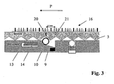
- FIGS. 1 to 3 show a schematic representation of an actuator 1 for an end stop for clockwise rotation, as a blocking device 1, which is part of a control element 2.
- a control element 2 which is part of a control element 2.
- generic control units 2 are primarily designed as a turntable, it is of course conceivable according to the invention that the ring gear 3, which forms the second part 3 in these embodiments, is arranged on the circumference of a turntable of the control unit 2.
- Such controls 2 are provided with a latching device 4, which is formed in this embodiment of a detent spring 5 and a ball 6.
- This locking device 4 generates a rest for the operator, which supplies a corresponding haptic feedback to the operator of the operating element 2, depending on the number of teeth 7 in the ring gear 3.
- other locking devices 4 in combination with a second part 3 are used.
- a groove 9 is provided in addition to the locking device 4, in which a ball 10 is movably and feasibly inserted.
- a permanent magnet 12 is installed in the first part 8.
- the ball 10 is held by the permanent magnet 12 in the rest position, that is at the lower end 11 of the groove 9.
- the first part 8 contains an electromagnet 13, which has a coil 14.
- the ball 10 at least partially consists of a magnetizable material.
- the FIG. 1 describes the operating unit in a rest position and at the same time shows a system with a blocking function as an actuator, in which the second part in the FIG. 1 moved to the left is blockable.
- the arrangement in the operating element 2 would have to be constructed correspondingly mirror-inverted.
- the switching thresholds 16 are shown in principle with main pawls 17 and between increments 18.
- the main pawls which are shown as wider lines 17 correspond in their distance to the spacing of the teeth 7 in the ring gear 3 and thus the catch.
- the example corresponds to an embodiment according to the subclaims. According to the subclaims, a threefold multiple is in this embodiment the main pauses, that is, the resolution of the angle encoder, formed as intermediate increments 18 and drawn.
- an arbitrary multiple of the main load 17 as Eiseninkremente 19 as indicated in the embodiment indicated by the dash-dotted line.
- the advantage here is the movement of the ball in the groove 9 dynamically, that is, in response to the rotational speed of the second part can be controlled.
- a high resolution due to a large resolution of the intermediate increments 18 between the main pawls 17, produces a high number of pulses, which in turn are convertible into signals for driving the coil 14 of the electromagnet.
- the switch-on threshold is dynamically adaptable to the relative movement between the first part 8 and the second part 3.
- the sprocket 3 is moved in the direction of arrow P, as in the FIG. 2 shown, on the one hand over the time to detect the individual increments 17, 18 of the opto-electronic means, the rotational speed of the ring gear 3 can be determined so that the coil 14 of the electromagnet 13 can be activated in dependence on the rotational speed of the ring gear 3. If the ring gear 3 is moved very quickly, an early activation of the coil, which has taken place well in advance of the blocking position, must move the ball 10 out of the lower end of the groove, in order to prevent a ratchet from passing over the ring gear 3.
- the toothed ring 3 is moved slowly, then a later activation of the coil 14, which takes place shortly before the blocking position, is sufficient to move the ball 10 into the upper end of the groove and thus to block the ring gear 3 and thus the relative movement. It is thus created the possibility of taking into account the times of construction of the inductances in the electromagnet in time with respect to the rotational movement of the ring gear. If the ring gear 3 is moved slowly, for example, only half the voltage can be switched to the coil, so that the ball 10 moves slower to the upper end of the groove 10.
- FIG. 2 Is exemplary in the FIG. 2 a dash 20 entered, in which the coil 14 is activated and in the FIG. 3 the path is marked with a dot-dash line 21, which the sprocket 3 covers after activation.
- a path of 2.1 mm is shown. This length corresponds approximately to the distance between the teeth. 7
- the rotational speed is detected here with an optical sensor, which may be a fork light barrier, for example.
- a coding disk located in this optical system is designed so that an n-fold resolution, that is to say a multiple of the main pegs 17, can be evaluated. This makes it possible to accurately detect the rotational speed.
- the blocking function is then blocked, for example, by means of a ball 10, which can be attracted via an electromagnet 13 and a ring gear 3. Depending on the rotational speed, this blocking element 3 is driven dynamically, that is adapted. At low rotational speeds, the blocking function is activated later.
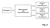
- FIG. 4 is a schematic diagram reproduce, which reflects the interaction between the angle sensor, the evaluation electronics and the actuator.
- any angle encoders can be used as angle encoders, wherein angle encoders, which are designed according to the principle of optoelectronic detection, are preferably used.
- the number of angle encoders is not limited, so that according to the invention also a superposition of the signals from encoders in the microcontroller of the evaluation electronics is conceivable.
- the angular movements for example, generated as pulses relative movements of the first 8 and second 3 part are detected by the transmitter and a main branch 17 or the increments 18, 19 assigned.
- the actuator 1 is moved into the correct position of the ring gear 3 to select a resolution in the angle encoder so here only main pauses 17, for example, the individual teeth 7, evaluate and depending on the relative movement a short before the Blocking position detected detent 17, 18, 19 to control or drive at a high relative movement detected far before the selected blocking position latching 17, 18, 19 for driving the actuator 1.
- the control unit in combination with angle sensor, transmitter and actuator 1 the possibility is now created dynamically, that is, to trigger the switch-on threshold for the actuator as a function of the relative movement. If, according to the invention, the resolution of the angle sensor is increased by a multiple of the main pauses, then the response accuracy and thus the control of the actuator 1 increases.
- the operating unit can be used for different functions. If, for example, the operating unit 2 is used for the ventilation control, then it is conceivable that this ventilation has three stages. The stages of ventilation, for example, each five Stilrasten 17 are spaced apart.
- the evaluation electronics, or the microcontroller located therein, defines the position 0 with an end stop, the positions 1 and 2 with a center detent and the position 3 with an end stop.
- the electronic evaluation the control signal for accurate achievement of the end stop of stage 3 must be done sooner or later. If the turntable is moved very quickly, the evaluation electronics sets the switch-on threshold to an increment 18 far in front of the blocking position that is actually to be reached, so that the blocking position in the switching stage 3 is unambiguously assigned to a position of the turntable. Accordingly, a very much closer to the blocking position located increment 18 or a main branch 17 is selected when the operator of the control element 2 the Turntable moves slowly.
- This dynamic adaptation of the selection of the switch-on threshold of the actuator 1 offers the advantage according to the invention that the blocking position is always unambiguously assigned. A driving over a blocking position is thus excluded.
- the FIG. 5 shows in its uppermost first diagram the force curve on a turntable in a control element 2 as almost sinusoidal.
- the dotted lines extending from the upper first diagram to the second middle diagram and the third lower diagram show the position of the ball 6 in the in FIG. 1 shown position.
- the main branch 17 in the angle encoder example of the maximum force can be assigned.
- the middle second diagram shows the pulse-shaped evaluation of the voltage as a function of a rotation angle ⁇ of a turntable of a control element 2 according to the invention.
- the evaluated pulses are entered in the diagram as vertical bars.
- the bottom diagram shows the division of an angle encoder in main pegs 17 and intermediate increments 18.
- the blocking device 1 blocks the rotational movement of the control unit 2 so that the force increases sharply, as shown in the upper diagram and the operator haptically receives feedback that an end stop has been reached.
- the power curve is deliberately limited, since it is customary to provide such turntable in operating units with slip clutches.
- the haptic feedback of the end stop is significantly above the haptic feedback that the operator experiences when he moves the control unit on the notches.
- Such a superposition according to the invention of a plurality of protractors and the knowledge of the control of the coils in the electromagnet permit a very precise actuation of the blocking device as a function of the relative movement in order to achieve a predefinable blocking position.
Landscapes
- Engineering & Computer Science (AREA)
- Physics & Mathematics (AREA)
- General Physics & Mathematics (AREA)
- General Engineering & Computer Science (AREA)
- Theoretical Computer Science (AREA)
- Automation & Control Theory (AREA)
- Human Computer Interaction (AREA)
- Combustion & Propulsion (AREA)
- Chemical & Material Sciences (AREA)
- Transportation (AREA)
- Mechanical Engineering (AREA)
- Mechanical Control Devices (AREA)
- Manipulator (AREA)
- Vehicle Body Suspensions (AREA)
- Massaging Devices (AREA)
- Steering Control In Accordance With Driving Conditions (AREA)
Description
- Die vorliegende Erfindung betrifft eine Bedieneinheit nach dem Oberbegriff des Patentanspruchs 1.
- Eine derartige Bedieneinheit ist aus der
EP 0 961 305 A2 bekannt. - Derartige Bedieneinheiten werden in Kraftfahrzeugen eingesetzt, wenn mittels einer Bedieneinrichtung unterschiedliche Funktionen steuerbar sind. Häufig ist es in Kraftfahrzeugen notwendig, einem Bedienelement unterschiedliche Funktionen zuzuweisen, wenn beispielsweise das Kraftfahrzeug ein Display aufweist, in den unterschiedlichste Bedienfunktionen angezeigt und auswählbar sind. So kann eine mit wenigen Stufen ausgestaltete Lüfterregulierung und eine mit vielen Stufen versehene Lautstärkeregelung mittels einer Bedieneinheit, die beispielsweise ein Bedienknopf, ein Drehteller oder ein Bedienelement ist, einzustellen sein.
- Um diese vielfachen Funktionen und Einstellungen in einer Bedieneinheit für den Bediener haptisch erkennbar zu gestalten, ist aus der unveröffentlichten
DE 10 2005 042 883 eine Blockiervorrichtung bekannt, mittels der eine individuelle Erzeugung von Endanschlägen an unterschiedlichsten Positionen einer Betätigungsvorrichtung darstellbar ist. Dieser Stand der Technik beschreibt die Anordnung einer Kugel in einer Nut, die mittels eines Elektromagneten positionierbar und mittels eines Permanentmagneten in ihre Ursprungsposition bewegbar ist. Hierbei rastet die Kugel in eine Verzahnung, des zweiten Teils, das relativ zur Nut bewegbar ist, durch die Aktivierung des Elektromagneten in die Verzahnung ein. Dabei verklemmt sich die Kugel zwischen der Verzahnung und der Nut und erzeugt dadurch eine für den Bediener haptisch erfassbare Begrenzung der Drehbewegung des Bedienelementes. Informationen über die Ansteuerung der Elektromagnete können der Druckschrift nicht entnommen werden. - Ein Beispiel für ein Wegmesssystem zur Erfassung einer Drehbewegung eines Bedienelementes einer Bedieneinheit in einem Kraftfahrzeug ist in der
DE 103 42 326 A1 beschrieben. Beschrieben ist ein Drehschalter bestehend aus einem Bedienelement, einer auf einer Leiterplatte angeordneten Lichtemissionseinrichtung und einem ebenfalls auf der Leiterplatte angeordneten das Licht auswertenden Empfänger, wobei die Lichtemissionseinrichtung und der Empfänger in der Weise angeordnet sind, das eine optoelektronische Erfassung von Schaltstellungen des Drehschalters ermöglicht ist, wobei die Lichtemissionseinrichtung im Inneren einer hohlzylinderförmigen Verlängerung des Bedienelementes, radial nach aussen gerichtet befestigt ist und die Verlängerung in Höhe der Lichtemissionseinrichtung regelmässig am Umfang verteilte Öffnungen aufweist und gegenüber der Lichtemissionseinrichtung, an der Aussenseite der Verlängerung mindestens zwei Empfänger angeordnet sind. Ein derartiger Winkelgeber ist in verschiedensten Ausführungsvarianten in Bedieneinheiten einsetzbar und je nach Anzahl der Öffnungen in der Verlängerung, sind unterschiedlichste Auflösungen in Bezug auf den Winkel des Verdrehens der Bedieneinheit detektierbar. Auf den Einsatz derartiger Winkelgeber wird hiermit ausdrücklich Bezug genommen, da derartige Wegmesssysteme als Winkelgeber in der erfindungsgemässen Bedieneinheit einsetzbar sind. - Ein weiteres Beispiel für einen optischen Absolutwertgeber ist in der
DE 103 53 429 A1 beschrieben. - Die in den zitierten Druckschriften genannten Winkelgeber stehen beispielhaft für inkrementale und absolute Winkelgeber, die in Erfindung einsetzbar sind. Darüber hinaus ist es natürlich selbstverständlich möglich bekannte Winkelgeber in einer erfindungsgemässen Bedieneinheit einzusetzen.
- Aufgabe der Erfindung ist es, eine Bedieneinheit bereitzustellen, mit der ein sicheres Betätigen einer Aktuatorik, das heisst einer Blockiereinrichtung, in Abhängigkeit einer Relativbewegung zweier gegeneinander bewegten Teile einer Bedieneinheit ermöglicht wird.
- Die erfindungsgemässe Aufgabe wird gelöst durch die Merkmale des Anspruchs 1.
- Durch die erfindungsgemässe Ausgestaltung der Bedieneinheit ist nun die Möglichkeit geschaffen, eine Bedieneinheit mit einer Blockiereinrichtung zu versehen, die ein verzögerungsfreies Einrasten einer Kugel in eine zwischen dem ersten Teil und dem zweiten Teil befindlichen Blockierposition zu ermöglichen. Hierbei wird die Aktuatorik je nach Relativbewegung zwischen erstem und zweitem Teil so weit oder kurz vor der eigentlichen Blockierposition angesteuert, dass die Blockiereinrichtung genau im richtigen Moment aktiviert wird, um in die Mittel zum Blockieren in die ausgewählte Position einklemmen zu können, so dass ein Überfahren einer Rast - beziehungsweise einer Blockierposition - vermieden wird. Durch den Einsatz eines Winkelgebers, der unmittelbar mit der Auswerteelektronik und der Aktuatorik zusammenwirkt, ist es nun möglich die Aktuatorik in Abhängigkeit der Drehbewegung, das heißt dynamisch in die Blockierposition zu bewegen.
- Ist das relativ zum ersten Teil bewegliche zweite Teil mit einer Verzahnung versehen, so ist es vorteilhaft, wenn die Auflösung des Winkelgebers mit der Anzahl der Blockierpositionen der Aktuatorik übereinstimmt. Ein weiterer Vorteil ergibt sich dann, wenn die Auflösung des Winkelgebers ein Vielfaches der Anzahl der Blockierpositionen ist. In Bezug auf ein Vielfaches ist es besonders vorteilhaft ein ganzzahliges Vielfaches, wie ein zweifaches, dreifaches, vierfaches, etc., der Anzahl der Blockierpositionen als Auflösung im Winkelgeber auszubilden. Anzumerken bleibt hier noch, dass auf die Ausgestaltungsvarianten der
DE 10 2005 042 883 unmittelbar Bezug genommen wird. - Nachfolgend wird die Erfindung anhand von Figuren in einem Ausführungsbeispiel näher erläutert. Es zeigt
- Figur 1
- den Schnitt durch eine prinzipielle Darstellung einer einseitig wirkenden Blockier- einrichtung, mit einer prinzipiell angedeuteten Auflösung eines Winkelgebers,
- Figur 2
- eine prinzipielle Darstellung einer erfindungsgemäßen Blockiereinrichtung in einer Bedieneinheit,
- Figur 3
- eine erfindungsgemäße Blockiereinrichtung in einer Stellung, in der das zweite Teil blockiert ist,
- Figur 4
- ein schematisches Schaltbild und
- Figur 5
- einen Spannungs- und Kräfteverlauf an der Bedieneinheit beziehungsweise in der Auswerteelektronik.
- Die
Figuren 1 bis 3 zeigen eine prinzipielle Darstellung einer Aktuatorik 1 für einen Endanschlag für das Rechtsdrehen, als Blockiereinrichtung 1, die Teil eines Bedienelementes 2 ist. Da gattungsgemäße Bedieneinheiten 2 vornehmlich als Drehsteller ausgebildet sind, ist es erfindungsgemäß natürlich vorstellbar, dass der Zahnkranz 3, der in diesen Ausführungsbeispielen das zweite Teil 3 bildet am Umfang eines Drehstellers der Bedieneinheit 2 angeordnet ist. Derartige Bedienelemente 2 sind mit einer Rasteinrichtung 4 versehen, die in diesen Ausführungsbeispiel aus einer Rastfeder 5 und einer Kugel 6 gebildet ist. Diese Rasteinrichtung 4 erzeugt für den Bediener eine Rast, die je nach Anzahl der Zähne 7 im Zahnkranz 3 eine entsprechende haptische Rückmeldung an den Bediener des Bedienelementes 2 liefert. Es ist natürlich selbstverständlich das auch andere Rasteinrichtungen 4 in Kombination mit einem zweiten Teil 3 einsetzbar sind. - Im ersten Teil 8 ist neben der Rasteinrichtung 4 eine Nut 9 vorgesehen, in der eine Kugel 10 beweglich und führbar eingelegt ist. Am unteren Ende 11 der Nut 9 ist im ersten Teil 8 ein Permanentmagnet 12 eingebaut. In der in der
Figur 1 dargestellten Ruhestellung des Bedienelementes 2 wird die Kugel 10 durch den Permanentmagneten 12 in der Ruheposition, das heißt am unteren Ende 11 der Nut 9 gehalten. Darüber hinaus enthält das erste Teil 8 einen Elektromagneten 13, der eine Spule 14 aufweist. Durch eine Aktivierung, das heißt eine Beaufschlagung der Spule 14 mit einer Spannung, ist die Kugel 10 in der Nut 9 vom unteren Ende 11 in eine Position am oberen Ende 15 der Nut 9 bewegbar. Hierbei ist es natürlich selbstverständlich, dass die Kugel 10 zumindest teilweise aus einem magnetisierbaren Werkstoff besteht. DieFigur 1 beschreibt die Bedieneinheit in einer Ruhestellung und zeigt gleichzeitig ein System, mit einer Blockierfunktion als Aktuatorik, in dem das zweite Teil in derFigur 1 nach links bewegt blockierbar ist. Bei einer Blockierung für nach rechts bewegte zweite Teile müsste die Anordnung im Bedienelement 2 entsprechend spiegelbildlich aufgebaut sein. Alternativ besteht natürlich ebenfalls die Möglichkeit eine beidseitig mit schrägen versehene Nut 9, wie aus dem Stand der Technik bekannt, einzusetzen. - Oberhalb des Zahnkranzes 3 sind prinzipiell die Schaltschwellen 16 mit Hauptrasten 17 und zwischen Inkrementen 18 dargestellt. Die Hauptrasten die als breitere Striche 17 dargestellt sind entsprechen in ihrem Abstand dem Abstand der Zähne 7 im Zahnkranz 3 und somit der Rast. Das Beispiel entspricht einer Ausgestaltungsform gemäß den Unteransprüchen. Entsprechend den Unteransprüchen ist in diesem Ausführungsbeispiel ein dreifaches Vielfaches der Hauptrasten, das heißt der Auflösung des Winkelgebers, als Zwischeninkremente 18 ausgebildet und eingezeichnet. Darüber hinaus ist ein beliebiges Vielfaches der Hauptrast 17 als Zwischeninkremente 19, wie in dem Ausführungsbeispiel mit der strichpunktierten Linie angedeutet realisierbar.
- Wird nun der Zahnkranz 3 in Richtung des Pfeils P, in der
Figur 1 nach links bewegt, wobei ein Drehsteller nach rechts verdreht werden würde, so detektiert der Winkelgeber zwischen den Hauptrasten 17 drei Zwischeninkremente 18, so dass zwischen jedem Zahn 7 des Zahnkranzes 3 vier ansteuerbare Impulse, zum Beispiel mittels einer opto-elektronischen Erfassung, detektierbar sind. Somit kann eine sehr genaue Ansteuerung der Bewegung der Kugel 10 in der Nut 9 in Bezug auf die Bewegung des Zahnkranzes 3 erfolgen. - Vorteilhaft ist hierbei das die Bewegung der Kugel in der Nut 9 dynamisch, das heißt in Abhängigkeit der Drehgeschwindigkeit des zweiten Teils ansteuerbar ist. Eine hohe Auflösung, durch eine große Auflösung der Zwischeninkremente 18 zwischen den Hauptrasten 17 erzeugt eine hohe Anzahl von Impulsen, die wiederum in Signale zur Ansteuerung der Spule 14 des Elektromagneten umwandelbar sind. Mittels einer erfindungsgemäß ausgestalteten Bedieneinheit ist die Einschaltschwelle dynamisch an die Relativbewegung zwischen erstem Teil 8 und zweitem Teil 3 anpaßbar.
- Wird nun der Zahnkranz 3 in Richtung des Pfeils P bewegt, wie in der
Figur 2 dargestellt, so ist einerseits über die Zeit zur Erfassung der einzelnen Inkremente 17, 18 der opto-elektronischen Mittel die Drehgeschwindigkeit des Zahnkranzes 3 ermittelbar, so dass in Abhängigkeit der Drehgeschwindigkeit des Zahnkranzes 3 die Spule 14 des Elektromagneten 13 aktivierbar ist. Wird der Zahnkranz 3 sehr schnell bewegt, muss ein frühzeitiges, weit vor der Blockierposition erfolgtes Aktivieren der Spule die Kugel 10 aus dem unteren Ende der Nut heraus bewegen, um kein Überfahren einer Rast im Zahnkranz 3 zu ermöglichen. Wird hingegen der Zahnkranz 3 langsam bewegt, so ist ein späteres, kurz vor der Blockierposition erfolgtes Aktivieren der Spule 14 ausreichend, um die Kugel 10 in das obere Ende der Nut zu bewegen und somit die Blockierung des Zahnkranzes 3 und damit der Relativbewegung zu bewerkstelligen. Es ist somit die Möglichkeit geschaffen, die Zeiten des Aufbaus der Induktivitäten in dem Elektromagneten zeitlich in Bezug auf die Drehbewegung des Zahnkranzes zu berücksichtigen. Wird der Zahnkranz 3 langsam bewegt, so kann beispielsweise lediglich die halbe Spannung auf die Spule geschaltet werden, so dass sich die Kugel 10 langsamer an das obere Ende der Nut 10 bewegt. Wird hingegen eine schnelle Bewegung am Zahnkranz 3 mittels der Inkremente 17, 18 detektiert, so wird die maximale Spannung auf die Spule 14 des Elektromagneten 13 gegeben und die Kugel 10 bewegt sich sehr schnell an das obere Ende 15 der Nut 10 wie inFigur 3 dargestellt. Die Kugel 10 blockiert in dieser Stellung die Bewegung des Zahnkranzes 3 nach links, also einer Verdrehrichtung nach rechts. - Beispielhaft ist in der
Figur 2 ein Strich 20 eingetragen, bei dem die Spule 14 aktiviert wird und in derFigur 3 ist der Weg mit einer strichpunktierten Linie 21 markiert, den der Zahnkranz 3 nach der Aktivierung zurücklegt. Beispielhaft ist inFigur 3 ein Weg von 2,1 mm dargestellt. Diese Länge entspricht in etwa auch dem Abstand zwischen den Zähnen 7. - Die Drehgeschwindigkeit wird hierbei mit einem optischen Sensor, der beispielsweise eine Gabellichtschranke sein kann, erfasst. Eine in diesem optischen System befindliche Codierscheibe ist dabei so ausgelegt, das eine n-fache Auflösung, das heißt ein Vielfaches der Hauptrasten 17 auswertbar ist. Hierdurch ist es möglich, die Drehgeschwindigkeit genau zu erfassen. Die Blockierfunktion wird dann zum Beispiel über eine Kugel 10, die über einen Elektromagneten 13 anziehbar ist und einen Zahnkranz 3 blockiert. In Abhängigkeit von der Drehgeschwindigkeit wird diese Blockierelement 3 dynamisch, das heißt angepasst angesteuert. Bei niedrigen Drehgeschwindigkeiten wird die Blockierfunktion später aktiviert. Bei höheren Drehgeschwindigkeiten muss die Blockierfunktion früher aktiviert werden, da sonst wegen der Kugelträgheit und dem Aufbau der Induktivitäten in der Spule der Zahnkranz 3 zu spät blockiert würde. Es ist somit eine dynamische Anpassung der Drehblockierung in einer zentralen Bedieneinheit realisierbar. Wird beispielsweise ein üblicher den Rasten entsprechender Encoder im Winkelgeber verwendet, der 36 Hauptrasten 17 aufweist, so es ist erfindungsgemäße vorstellbar, pro mechanischer Rast zwei Schaltpunkte zu realisieren, in dem zwischen jede Hauptrast 17 ein Zwischeninkrement 18 installiert wird, so dass die Auflösung des optischen Encoders von 36 auf 72 erfolgt.
- In der
Figur 4 ist ein schematisches Schaltbild wiedergeben, welches das Zusammenspiel zwischen dem Winkelgeber, der Auswertelektronik und der Aktuatorik wiedergibt. Als Winkelgeber sind hierbei beliebige Winkelgeber einsetzbar, wobei Winkelgeber, die nach den Prinzip der optoelektronischen Erfassung ausgebildet sind, bevorzugt eingesetzt werden. Hierbei ist die Anzahl der Winkelgeber nicht beschränkt, so dass erfindungsgemäß auch eine Überlagerung der Signale von Winkelgebern in dem Mikrocontroller der Auswertelektronik vorstellbar ist. Die von Winkelgeber, zum Beispiel als Impulse generierten Relativbewegungen des ersten 8 und zweiten 3 Teils werden von der Auswerteelektronik erfasst und einer Hauptrast 17 oder den Inkrementen 18, 19 zugeordnet. Vorstellbar ist es nun, damit die Aktuatorik 1 in die richtige Stelle des Zahnkranzes 3 hineinbewegt wird, eine Auflösung im Winkelgeber derart zu wählen, das hier lediglich Hauptrasten 17, die beispielsweise den einzelnen Zähnen 7 entsprechen, auszuwerten und je nach Relativbewegung eine kurz vor der Blockierposition detektierte Rast 17, 18, 19 anzusteuern oder bei einer hohen Relativbewegung eine weit vor der ausgewählten Blockierposition detektierte Rast 17, 18, 19 zur Ansteuerung der Aktuatorik 1 anzusteuern. Durch den erfindungsgemäßen Aufbau der Bedieneinheit in Kombination mit Winkelgeber, Auswerteelektronik und Aktuatorik 1 ist nun die Möglichkeit geschaffen, dynamisch, das heißt in Abhängigkeit der Relativbewegung die Einschaltschwelle für die Aktuatorik anzusteuern. Wird nun erfindungsgemäß die Auflösung des Winkelgebers um ein Vielfaches der Hauptrasten erhöht, so erhöht sich die Ansprechgenauigkeit und somit die Steuerung der Aktuatorik 1. - Wie in der
Figur 4 weiterhin dargestellt, ist es erfindungsgemäß vorstellbar mittels der Aktuatorik einen Endanschlag für rechts, eine Mittenrast und/oder einen Endanschlag für links zu realisieren. Wesentlich hierbei ist, dass je nach ausgewähltem Menüpunkt die Bedieneinheit für unterschiedliche Funktionen einsetzbar ist. Wird beispielsweise die Bedieneinheit 2 für die Lüftungsregelung eingesetzt, so ist es vorstellbar, dass diese Lüftung drei Stufen aufweist. Die Stufen der Lüftung können beispielsweise jeweils fünf Hauptrasten 17 voneinander beabstandet sein. Die Auswertelektronik, beziehungsweise der hierin befindliche Mikrocontroller, legt hierin die Position 0 mit einem Endanschlag, die Positionen 1 und 2 mit einem Mittenrast und die Position 3 mit einem Endanschlag fest. Will nun der Bediener die Lüftung von Stufe 1 auf die Stufe 3 bewegen, so ist in der Auswerteelektronik erkennbar, dass beim Erreichen der Stufe 3 zehn Rasten zu verfahren sind. Je nach Geschwindigkeit des Verdrehens des Drehstellers der Bedieneinheit 2 muß nun die Auswertelektronik das Steuersignal zur genauen Erreichung des Endanschlags der Stufe 3 früher oder später erfolgen. Wird der Drehsteller sehr schnell bewegt, so legt die Auswerteelektronik die Einschaltschwelle auf ein Inkrement 18 weit vor der eigentlich zu erreichenden Blockierposition, so dass die Blockierposition in der Schaltstufe 3 eindeutig einer Stellung des Drehstellers zugeordnet ist. Entsprechend wird ein sehr viel näher an der Blockierposition befindliches Inkrement 18 oder eine Hauptrast 17 ausgewählt, wenn der Bediener des Bedienelementes 2 den Drehsteller langsam bewegt. Diese dynamische Anpassung der Auswahl der Einschaltschwelle der Aktuatorik 1 bietet den erfindungsgemäßen Vorteil, dass die Blockierposition stets eindeutig zugeordnet wird. Ein Überfahren einer Blockierposition wird somit ausgeschlossen. - Die
Figur 5 zeigt in ihrem obersten ersten Diagramm den Kraftverlauf an einem Drehsteller in einem Bedienelement 2 als nahezu sinusförmig auf. Die punktierten Linien, die sich vom oberen ersten Diagramm über das zweite mittlere Diagramm und das dritte untere Diagramm erstrecken, zeigen, die Position der Kugel 6 in der inFigur 1 gezeigten Position. Hierbei ist die Hauptrast 17 im Winkelgeber beispielhaft der maximalen Kraft zuordbar. Das mittlere zweite Diagramm zeigt die impulsförmige Auswertung der Spannung in Abhängigkeit eines Drehwinkels α eines Drehstellers eines erfindungsgemäßen Bedienelementes 2. Die ausgewerteten Impulse sind in dem Diagramm als senkrechte Striche eingetragen. Das unterste Diagramm zeigt die Aufteilung eines Winkelgebers in Hauptrasten 17 und Zwischeninkremente 18. Wird nun zu einem Zeitpunkt t1 die Aktuatorik mittels der Auswerteelektronik angesteuert, so blockiert die Blockiereinrichtung 1 die Drehbewegung der Bedieneinheit 2 so dass die Kraft, wie im oberen Diagramm dargestellt stark ansteigt, und der Bediener haptisch eine Rückmeldung erfährt, dass ein Endanschlag erreicht ist. Der Kraftverlauf ist dabei bewusst begrenzt wiedergegeben, da es üblich ist, derartige Drehsteller in Bedieneinheiten mit Rutschkupplungen zu versehen. Die haptische Rückmeldung des Endanschlages liegt dabei aber deutlich über der haptischen Rückmeldung, die der Bediener erfährt, wenn er die Bedieneinheit über die Rasten bewegt. - In dem untersten Diagramm der
Figur 5 ist zusätzlich der Verlauf einer analogen Spannung über einen Drehwinkel α wiedergegeben. Derartige Spannungsverläufe sind ebenfalls mittels optoelektronischer Mittel, das heißt mit Sender und Empfänger erzielbar, und können erfindungsgemäß parallel als zusätzliche Winkelgeber in erfindungsgemäßen Bedieneinheiten 2 eingesetzt werden. Durch eine überlagerte Auswertung in der Auswerteelektronik ist aus den Hauptrasten 17, den Inkrementen 18 und dem Spannungsverlauf 21 eine beliebig genaue Auflösung des Winkelgebers beziehungsweise in diesem Beispiel der beiden Winkelgeber ermittelbar. Durch eine derartige erfindungsgemäße Überlagerung von mehreren Winkelmessern und dem Wissen über die Ansteuerung der Spulen im Elektromagnet ist eine sehr genaue Ansteuerung der Blockiereinrichtung in Abhängigkeit der Relativbewegung zur Erzielung einer vorgebbaren Blockierposition ermöglicht.
Claims (7)
- Bedieneinheit (2) für einen Drehsteller in einem Kraftfährzeug, mit einem ersten Teil (8), mit einem relativ zum ersten Teil (8) beweglichen zweiten Teil (3), mit einer Auswerteelektronik, mit mindestens einem Winkelgeber zur Erfassung der Relativbewegung, wobei der Winkelgeber eine Auflösung aufweist und mit der Auswerteelektronik elektrisch verbunden ist, und mit einer Aktuatorik (1) zum mindestens teilweisen Blockieren der Relativbewegung, wobei die Aktuatorik (1) mittels der Auswerteelektronik steuerbar ist, wobei die Auswerteelektronik die Aktuatorik (1) in Abhängigkeit der Relativbewegung steuert, dadurch gekennzeichnet, dass bei einer hohen Relativbewegung des zweiten Teils (3) relativ zum ersten Teil (8) die Aktuatorik (1) weit vor und bei einer geringen Relativbewegung kurz vor einer vorgebbaren Blockierposition (20) ansteuert und dass die Auflösung des Winkelgebers ein ganzzahliges Vielfaches der Anzahl der Blockierpositionen ist.
- Bedieneinheit (2) nach Anspruch 1, dadurch gekennzeichnet, dass eine Einrichtung (4) zur Erzeugung einer Rast zwischen dem ersten Teil (8) und dem zweiten Teil (3) befestigt ist.
- Bedieneinheit (2) nach Anspruch 2, dadurch gekennzeichnet, dass jede Rastposition mit einer Blockierposition (20) übereinstimmt.
- Bedieneinheit (2) nach einem der vorstehenden Ansprüche, dadurch gekennzeichnet, dass der Winkelgeber ein inkrementaler Winkelgeber ist.
- Bedieneinheit (2) nach Anspruch 4, dadurch gekennzeichnet, dass der Winkelgeber aus mindestens einer Lichtemissionseinrichtung, mindestens einer Lichtabsorptionseinrichtung und mindestens einer zwischen der Lichtemissions- und Lichtabsorptionseinrichtung befindlichen Blende gebildet ist, die in der Weise angeordnet sind, das eine optoelektronische Erfassung der Relativbewegung detektierbar ist
- Bedieneinheit (2) nach einem der Ansprüche 4 und 5, dadurch gekennzeichnet, dass mittels der optoelektronischen Erfassung eine absolute und/oder inkrementale Erfassung der Relativbewegung erfassbar ist.
- Bedieneinheit (2) nach einem der vorstehenden Ansprüche, dadurch gekennzeichnet, dass die Aktuatorik (1) aus mindestens einer geführten Kugel (7) und mindestens einem der Kugel (7) zugeordneten Elektromagneten (13) gebildet ist, wobei die Kugel (7) durch den Elektromagneten (13) derart zwischen das erste Teil (8) und das zweite Teil (3) verschiebbar ist, dass die Bewegung des zweiten Teiles (3) zumindest teilweise blockiert ist.
Applications Claiming Priority (2)
| Application Number | Priority Date | Filing Date | Title |
|---|---|---|---|
| DE102006018522A DE102006018522B4 (de) | 2006-04-21 | 2006-04-21 | Steuerung für eine Bedieneinheit |
| PCT/EP2007/002921 WO2007121830A1 (de) | 2006-04-21 | 2007-03-31 | Steuerung für eine bedieneinheit |
Publications (2)
| Publication Number | Publication Date |
|---|---|
| EP2010985A1 EP2010985A1 (de) | 2009-01-07 |
| EP2010985B1 true EP2010985B1 (de) | 2010-07-21 |
Family
ID=38222626
Family Applications (1)
| Application Number | Title | Priority Date | Filing Date |
|---|---|---|---|
| EP07723862A Active EP2010985B1 (de) | 2006-04-21 | 2007-03-31 | Steuerung für eine bedieneinheit |
Country Status (4)
| Country | Link |
|---|---|
| EP (1) | EP2010985B1 (de) |
| AT (1) | ATE475126T1 (de) |
| DE (2) | DE102006018522B4 (de) |
| WO (1) | WO2007121830A1 (de) |
Families Citing this family (2)
| Publication number | Priority date | Publication date | Assignee | Title |
|---|---|---|---|---|
| JP4969560B2 (ja) * | 2008-11-27 | 2012-07-04 | アルプス電気株式会社 | 操作感触付与型入力装置 |
| DE102010055831A1 (de) * | 2010-12-23 | 2012-06-28 | Inventus Engineering Gmbh | Übertragungsvorrichtung |
Family Cites Families (8)
| Publication number | Priority date | Publication date | Assignee | Title |
|---|---|---|---|---|
| WO1980002135A1 (en) * | 1979-04-05 | 1980-10-16 | Otis Elevator Co | Modified slowdown and braking of an elevator car |
| US5209661A (en) * | 1990-10-29 | 1993-05-11 | Systems Control Technology, Inc. | Motor control desired dynamic load of a simulating system and method |
| DE19824149A1 (de) * | 1998-05-29 | 1999-12-02 | Nokia Mobile Phones Ltd | Drehsteller für elektrische oder elektronische Geräte |
| JP4209235B2 (ja) * | 2003-03-28 | 2009-01-14 | アルプス電気株式会社 | 力覚付与型入力装置 |
| US6917867B2 (en) * | 2003-04-10 | 2005-07-12 | Caterpillar Inc | Operator input device with tactile feedback |
| DE10342326B4 (de) * | 2003-09-11 | 2007-10-04 | Preh Gmbh | Integrierter optischer Encoder |
| DE10353429B4 (de) * | 2003-11-15 | 2006-10-19 | Preh Gmbh | Optischer Absolutwertgeber |
| DE102005042883B4 (de) * | 2005-06-02 | 2008-05-08 | Preh Gmbh | Bestätigungsvorrichtung mit Mitteln zum Blockieren von Bewegungen |
-
2006
- 2006-04-21 DE DE102006018522A patent/DE102006018522B4/de not_active Expired - Lifetime
-
2007
- 2007-03-31 DE DE502007004488T patent/DE502007004488D1/de active Active
- 2007-03-31 WO PCT/EP2007/002921 patent/WO2007121830A1/de not_active Ceased
- 2007-03-31 AT AT07723862T patent/ATE475126T1/de active
- 2007-03-31 EP EP07723862A patent/EP2010985B1/de active Active
Also Published As
| Publication number | Publication date |
|---|---|
| EP2010985A1 (de) | 2009-01-07 |
| ATE475126T1 (de) | 2010-08-15 |
| DE102006018522B4 (de) | 2008-01-03 |
| DE502007004488D1 (de) | 2010-09-02 |
| WO2007121830A1 (de) | 2007-11-01 |
| DE102006018522A1 (de) | 2007-10-25 |
Similar Documents
| Publication | Publication Date | Title |
|---|---|---|
| EP2914879B1 (de) | Vorrichtung und verfahren zum auswählen einer schalterstellung | |
| DE102004049011A1 (de) | Drehsteller | |
| DE19824149A1 (de) | Drehsteller für elektrische oder elektronische Geräte | |
| EP0938646B1 (de) | Anordnungen zum erfassen einer rotatorischen oder translatorischen bewegung | |
| WO2001000462A1 (de) | Vorrichtung zur positionserkennung eines beweglichen glieds in einem bei fahrzeugen anwendbaren verschluss | |
| WO1999010615A1 (de) | Kraftfahrzeug-schliessvorrichtung mit einer positionserkennung eines sich bewegenden stellelementes | |
| DE102012014946A1 (de) | Elektronischer Betätigungsschalter für Wasserarmaturen | |
| EP3352533A1 (de) | Lichtstellpult mit doppelwellenencoder | |
| EP2010985B1 (de) | Steuerung für eine bedieneinheit | |
| DE102004035960B4 (de) | Drehsteller | |
| WO2005027352A1 (de) | Integrierter optischer encoder | |
| DE102012017266B4 (de) | Bedienvorrichtung für eine Funktionseinrichtung eines Kraftfahrzeugs sowie Kraftfahrzeug | |
| DE102014116827B4 (de) | Doppelwellenencoder | |
| DE102012018291B4 (de) | Bedienvorrichtung für eine Funktionseinrichtung eines Kraftfahrzeugs | |
| DE3243956A1 (de) | Positionsgeber zur lagebestimmung linear verfahrbarer maschinenteile | |
| EP1740910B1 (de) | Drehsteller | |
| DE19843143C1 (de) | Kodierer zur Umwandlung einer analogen Eingabe in Digitalsignale | |
| DE102005055307A1 (de) | Drehsteller mit inkrementellem Drehwinkelgeber | |
| DE19717215A1 (de) | Optischer Inkrementgeber | |
| DE102008058650B4 (de) | Drehstellungssensorsystem | |
| DE19947483B4 (de) | Kraftfahrzeug-Türschloss | |
| DE102008049679A1 (de) | Schaltermodul mit Sensormitteln zur Erkennung von Schaltpositionen | |
| DE202016005830U1 (de) | Drehsteller zur Bedienung von Funktionen eines Kraftfahrzeugs, Kraftfahrzeug | |
| DE10360016B3 (de) | Bedienvorrichtung mit digitalen Hallsensoren | |
| DE3330500C2 (de) | Schaltungsanordnung zur Störimpulsunterdrückung |
Legal Events
| Date | Code | Title | Description |
|---|---|---|---|
| PUAI | Public reference made under article 153(3) epc to a published international application that has entered the european phase |
Free format text: ORIGINAL CODE: 0009012 |
|
| 17P | Request for examination filed |
Effective date: 20081115 |
|
| AK | Designated contracting states |
Kind code of ref document: A1 Designated state(s): AT BE BG CH CY CZ DE DK EE ES FI FR GB GR HU IE IS IT LI LT LU LV MC MT NL PL PT RO SE SI SK TR |
|
| AX | Request for extension of the european patent |
Extension state: AL BA HR MK RS |
|
| 17Q | First examination report despatched |
Effective date: 20090224 |
|
| GRAP | Despatch of communication of intention to grant a patent |
Free format text: ORIGINAL CODE: EPIDOSNIGR1 |
|
| GRAS | Grant fee paid |
Free format text: ORIGINAL CODE: EPIDOSNIGR3 |
|
| GRAA | (expected) grant |
Free format text: ORIGINAL CODE: 0009210 |
|
| AK | Designated contracting states |
Kind code of ref document: B1 Designated state(s): AT BE BG CH CY CZ DE DK EE ES FI FR GB GR HU IE IS IT LI LT LU LV MC MT NL PL PT RO SE SI SK TR |
|
| REG | Reference to a national code |
Ref country code: GB Ref legal event code: FG4D Free format text: NOT ENGLISH |
|
| REG | Reference to a national code |
Ref country code: CH Ref legal event code: EP |
|
| REG | Reference to a national code |
Ref country code: IE Ref legal event code: FG4D |
|
| REF | Corresponds to: |
Ref document number: 502007004488 Country of ref document: DE Date of ref document: 20100902 Kind code of ref document: P |
|
| REG | Reference to a national code |
Ref country code: NL Ref legal event code: VDEP Effective date: 20100721 |
|
| LTIE | Lt: invalidation of european patent or patent extension |
Effective date: 20100721 |
|
| PG25 | Lapsed in a contracting state [announced via postgrant information from national office to epo] |
Ref country code: NL Free format text: LAPSE BECAUSE OF FAILURE TO SUBMIT A TRANSLATION OF THE DESCRIPTION OR TO PAY THE FEE WITHIN THE PRESCRIBED TIME-LIMIT Effective date: 20100721 Ref country code: FI Free format text: LAPSE BECAUSE OF FAILURE TO SUBMIT A TRANSLATION OF THE DESCRIPTION OR TO PAY THE FEE WITHIN THE PRESCRIBED TIME-LIMIT Effective date: 20100721 Ref country code: LT Free format text: LAPSE BECAUSE OF FAILURE TO SUBMIT A TRANSLATION OF THE DESCRIPTION OR TO PAY THE FEE WITHIN THE PRESCRIBED TIME-LIMIT Effective date: 20100721 |
|
| REG | Reference to a national code |
Ref country code: IE Ref legal event code: FD4D |
|
| PG25 | Lapsed in a contracting state [announced via postgrant information from national office to epo] |
Ref country code: BG Free format text: LAPSE BECAUSE OF FAILURE TO SUBMIT A TRANSLATION OF THE DESCRIPTION OR TO PAY THE FEE WITHIN THE PRESCRIBED TIME-LIMIT Effective date: 20101021 Ref country code: SI Free format text: LAPSE BECAUSE OF FAILURE TO SUBMIT A TRANSLATION OF THE DESCRIPTION OR TO PAY THE FEE WITHIN THE PRESCRIBED TIME-LIMIT Effective date: 20100721 Ref country code: PT Free format text: LAPSE BECAUSE OF FAILURE TO SUBMIT A TRANSLATION OF THE DESCRIPTION OR TO PAY THE FEE WITHIN THE PRESCRIBED TIME-LIMIT Effective date: 20101122 Ref country code: PL Free format text: LAPSE BECAUSE OF FAILURE TO SUBMIT A TRANSLATION OF THE DESCRIPTION OR TO PAY THE FEE WITHIN THE PRESCRIBED TIME-LIMIT Effective date: 20100721 Ref country code: IS Free format text: LAPSE BECAUSE OF FAILURE TO SUBMIT A TRANSLATION OF THE DESCRIPTION OR TO PAY THE FEE WITHIN THE PRESCRIBED TIME-LIMIT Effective date: 20101121 Ref country code: CY Free format text: LAPSE BECAUSE OF FAILURE TO SUBMIT A TRANSLATION OF THE DESCRIPTION OR TO PAY THE FEE WITHIN THE PRESCRIBED TIME-LIMIT Effective date: 20100721 |
|
| PG25 | Lapsed in a contracting state [announced via postgrant information from national office to epo] |
Ref country code: LV Free format text: LAPSE BECAUSE OF FAILURE TO SUBMIT A TRANSLATION OF THE DESCRIPTION OR TO PAY THE FEE WITHIN THE PRESCRIBED TIME-LIMIT Effective date: 20100721 Ref country code: GR Free format text: LAPSE BECAUSE OF FAILURE TO SUBMIT A TRANSLATION OF THE DESCRIPTION OR TO PAY THE FEE WITHIN THE PRESCRIBED TIME-LIMIT Effective date: 20101022 Ref country code: SE Free format text: LAPSE BECAUSE OF FAILURE TO SUBMIT A TRANSLATION OF THE DESCRIPTION OR TO PAY THE FEE WITHIN THE PRESCRIBED TIME-LIMIT Effective date: 20100721 |
|
| PG25 | Lapsed in a contracting state [announced via postgrant information from national office to epo] |
Ref country code: IE Free format text: LAPSE BECAUSE OF FAILURE TO SUBMIT A TRANSLATION OF THE DESCRIPTION OR TO PAY THE FEE WITHIN THE PRESCRIBED TIME-LIMIT Effective date: 20100721 Ref country code: DK Free format text: LAPSE BECAUSE OF FAILURE TO SUBMIT A TRANSLATION OF THE DESCRIPTION OR TO PAY THE FEE WITHIN THE PRESCRIBED TIME-LIMIT Effective date: 20100721 |
|
| PLBE | No opposition filed within time limit |
Free format text: ORIGINAL CODE: 0009261 |
|
| STAA | Information on the status of an ep patent application or granted ep patent |
Free format text: STATUS: NO OPPOSITION FILED WITHIN TIME LIMIT |
|
| PG25 | Lapsed in a contracting state [announced via postgrant information from national office to epo] |
Ref country code: CZ Free format text: LAPSE BECAUSE OF FAILURE TO SUBMIT A TRANSLATION OF THE DESCRIPTION OR TO PAY THE FEE WITHIN THE PRESCRIBED TIME-LIMIT Effective date: 20100721 Ref country code: EE Free format text: LAPSE BECAUSE OF FAILURE TO SUBMIT A TRANSLATION OF THE DESCRIPTION OR TO PAY THE FEE WITHIN THE PRESCRIBED TIME-LIMIT Effective date: 20100721 Ref country code: RO Free format text: LAPSE BECAUSE OF FAILURE TO SUBMIT A TRANSLATION OF THE DESCRIPTION OR TO PAY THE FEE WITHIN THE PRESCRIBED TIME-LIMIT Effective date: 20100721 Ref country code: SK Free format text: LAPSE BECAUSE OF FAILURE TO SUBMIT A TRANSLATION OF THE DESCRIPTION OR TO PAY THE FEE WITHIN THE PRESCRIBED TIME-LIMIT Effective date: 20100721 Ref country code: IT Free format text: LAPSE BECAUSE OF FAILURE TO SUBMIT A TRANSLATION OF THE DESCRIPTION OR TO PAY THE FEE WITHIN THE PRESCRIBED TIME-LIMIT Effective date: 20100721 |
|
| 26N | No opposition filed |
Effective date: 20110426 |
|
| PG25 | Lapsed in a contracting state [announced via postgrant information from national office to epo] |
Ref country code: ES Free format text: LAPSE BECAUSE OF FAILURE TO SUBMIT A TRANSLATION OF THE DESCRIPTION OR TO PAY THE FEE WITHIN THE PRESCRIBED TIME-LIMIT Effective date: 20101101 |
|
| REG | Reference to a national code |
Ref country code: DE Ref legal event code: R097 Ref document number: 502007004488 Country of ref document: DE Effective date: 20110426 |
|
| BERE | Be: lapsed |
Owner name: PREH G.M.B.H. Effective date: 20110331 |
|
| PG25 | Lapsed in a contracting state [announced via postgrant information from national office to epo] |
Ref country code: MC Free format text: LAPSE BECAUSE OF NON-PAYMENT OF DUE FEES Effective date: 20110331 |
|
| REG | Reference to a national code |
Ref country code: CH Ref legal event code: PL |
|
| GBPC | Gb: european patent ceased through non-payment of renewal fee |
Effective date: 20110331 |
|
| PG25 | Lapsed in a contracting state [announced via postgrant information from national office to epo] |
Ref country code: MT Free format text: LAPSE BECAUSE OF FAILURE TO SUBMIT A TRANSLATION OF THE DESCRIPTION OR TO PAY THE FEE WITHIN THE PRESCRIBED TIME-LIMIT Effective date: 20100721 Ref country code: BE Free format text: LAPSE BECAUSE OF NON-PAYMENT OF DUE FEES Effective date: 20110331 |
|
| PG25 | Lapsed in a contracting state [announced via postgrant information from national office to epo] |
Ref country code: LI Free format text: LAPSE BECAUSE OF NON-PAYMENT OF DUE FEES Effective date: 20110331 Ref country code: CH Free format text: LAPSE BECAUSE OF NON-PAYMENT OF DUE FEES Effective date: 20110331 |
|
| PG25 | Lapsed in a contracting state [announced via postgrant information from national office to epo] |
Ref country code: GB Free format text: LAPSE BECAUSE OF NON-PAYMENT OF DUE FEES Effective date: 20110331 |
|
| REG | Reference to a national code |
Ref country code: AT Ref legal event code: MM01 Ref document number: 475126 Country of ref document: AT Kind code of ref document: T Effective date: 20120331 |
|
| PG25 | Lapsed in a contracting state [announced via postgrant information from national office to epo] |
Ref country code: LU Free format text: LAPSE BECAUSE OF NON-PAYMENT OF DUE FEES Effective date: 20110331 |
|
| PG25 | Lapsed in a contracting state [announced via postgrant information from national office to epo] |
Ref country code: AT Free format text: LAPSE BECAUSE OF NON-PAYMENT OF DUE FEES Effective date: 20120331 |
|
| PG25 | Lapsed in a contracting state [announced via postgrant information from national office to epo] |
Ref country code: TR Free format text: LAPSE BECAUSE OF FAILURE TO SUBMIT A TRANSLATION OF THE DESCRIPTION OR TO PAY THE FEE WITHIN THE PRESCRIBED TIME-LIMIT Effective date: 20100721 |
|
| PG25 | Lapsed in a contracting state [announced via postgrant information from national office to epo] |
Ref country code: HU Free format text: LAPSE BECAUSE OF FAILURE TO SUBMIT A TRANSLATION OF THE DESCRIPTION OR TO PAY THE FEE WITHIN THE PRESCRIBED TIME-LIMIT Effective date: 20100721 |
|
| REG | Reference to a national code |
Ref country code: FR Ref legal event code: PLFP Year of fee payment: 10 |
|
| REG | Reference to a national code |
Ref country code: DE Ref legal event code: R082 Ref document number: 502007004488 Country of ref document: DE Representative=s name: LOHMANNS, BERNARD, DIPL.-PHYS., DE |
|
| REG | Reference to a national code |
Ref country code: FR Ref legal event code: PLFP Year of fee payment: 11 |
|
| REG | Reference to a national code |
Ref country code: FR Ref legal event code: PLFP Year of fee payment: 12 |
|
| PGFP | Annual fee paid to national office [announced via postgrant information from national office to epo] |
Ref country code: FR Payment date: 20240320 Year of fee payment: 18 |
|
| PG25 | Lapsed in a contracting state [announced via postgrant information from national office to epo] |
Ref country code: FR Free format text: LAPSE BECAUSE OF NON-PAYMENT OF DUE FEES Effective date: 20250331 |
|
| PGFP | Annual fee paid to national office [announced via postgrant information from national office to epo] |
Ref country code: DE Payment date: 20260320 Year of fee payment: 20 |