EP2010707B1 - Reinigungsmaschine - Google Patents
Reinigungsmaschine Download PDFInfo
- Publication number
- EP2010707B1 EP2010707B1 EP07716071A EP07716071A EP2010707B1 EP 2010707 B1 EP2010707 B1 EP 2010707B1 EP 07716071 A EP07716071 A EP 07716071A EP 07716071 A EP07716071 A EP 07716071A EP 2010707 B1 EP2010707 B1 EP 2010707B1
- Authority
- EP
- European Patent Office
- Prior art keywords
- driving unit
- compartment
- housing
- treatment
- cleaning machine
- Prior art date
- Legal status (The legal status is an assumption and is not a legal conclusion. Google has not performed a legal analysis and makes no representation as to the accuracy of the status listed.)
- Not-in-force
Links
Images
Classifications
-
- D—TEXTILES; PAPER
- D06—TREATMENT OF TEXTILES OR THE LIKE; LAUNDERING; FLEXIBLE MATERIALS NOT OTHERWISE PROVIDED FOR
- D06F—LAUNDERING, DRYING, IRONING, PRESSING OR FOLDING TEXTILE ARTICLES
- D06F43/00—Dry-cleaning apparatus or methods using volatile solvents
- D06F43/02—Dry-cleaning apparatus or methods using volatile solvents having one rotary cleaning receptacle only
Definitions
- the present invention relates a cleaning machine, such as a laundry cleaning machine, comprising a fluid tight pressure vessel defined by a pressure vessel housing.
- Cleaning machines which are used with non-aqueous cleaning mediums such as dry cleaning machines for use with densified liquid treatment gas, for example carbon dioxide, are known.
- Such cleaning machines are usually equipped with a treatment chamber in which a drum is rotatably arranged for receiving objects to be cleaned, such as laundry, and a driving unit, which is operable to rotate the drum.
- the driving unit is placed outside of the treatment chamber and acts on a shaft of the drum passing though a wall of the treatment chamber.
- US 2,539,407 and US 6,148,647 disclose typical conventional cleaning machines where the first describes a clean dry machine and the latter a household washing machine (using water to clean the laundry) Since it is difficult to properly seal the rotating shaft due to the high pressure inside the treatment chamber, the driving unit of more recent machines is placed inside the treatment chamber.
- the drum of the cleaning machine should be easily accessible for loading and unloading the laundry. Therefore the driving unit is usually located behind the drum in the treatment chamber of the cleaning machine, c.f. for example US 6,351,973 B1 , where a cleaning apparatus for use with carbon dioxide is described.
- a problem associated with these known cleaning machines is that the drum has to be removed in order to enable access to the driving unit, for example a motor and possibly a transmission, for service purposes or repairs. This is a time consuming and tedious operation, especially for a machines running with densified liquid state treatment gas, such as carbon dioxide, where the components are robust and correspondingly heavy in order to withstand the high pressure in such machines.
- the driving unit can only be reached through the washing chamber of the machine. Since the washing chamber usually is very narrow for an operator to crawl into, if at all possible, the access to the driving unit may nevertheless be restricted.
- the driving unit compartment housing being arranged protruding from the treatment compartment housing and the removable closing member including a portion of the driving unit compartment housing, it is sufficient to remove the closing member for accessing the driving unit compartment.
- the driving unit compartment is accessible from outside of the cleaning machine without having to pass through the treatment compartment. Consequently, the access to the driving unit compartment is considerably facilitated compared to the prior art machines.
- the invention relates to cleaning machines for washing articles, such as garments and fabrics, and for domestic or professional use.
- the invention relates especially to cleaning machines adapted to be used with liquified treatment gas, such as carbon dioxide.
- the cleaning machine according to the invention includes a fluid tight pressure vessel housing defining a pressure vessel.
- the fluid tight pressure vessel prevents the cleaning medium from escaping the pressure vessel, which could be harmful if an unhealthy cleaning medium is used, for example carbon dioxide.
- the cleaning machine includes a treatment compartment and a driving unit compartment defined by a treatment compartment housing and a driving unit compartment housing respectively.
- the objects to be cleaned are treated with the cleaning fluid.
- any items may be housed in the driving unit compartment and preferably components of the cleaning machine which are liable to service and repairs, such as at least a portion of a motor and/or a transmission arrangement.
- the treatment compartment and the driving unit compartment are in fluid communication with each other.
- An advantage herewith is that the need of a fluid and pressure tight sealing between the driving unit compartment and the treatment compartment is eliminated.
- a fluid tight pressure seal is difficult and expensive to obtain due to the rotating shaft, especially if there are high pressure differences such as in carbon dioxide machines.
- Electrical motors are known from the prior art, which function well if exposed to the high pressure and gas of a carbon dioxide dry cleaning machine, c.f. for example US 6,351,973 B1 . Consequently, according to the invention, fluid is allowed to travel between the treatment compartment and driving unit compartment such that any pressure differences are equalized.
- a portion of the pressure vessel housing constitutes a treatment compartment hosing and a portion of the pressure vessel housing constitutes the driving unit compartment housing.
- the treatment compartment housing and the driving unit compartment housing are arranged such that driving unit compartment housing forms a protrusion at the treatment compartment housing.
- the driving unit compartment is a separate extension of the treatment compartment having a smaller cross section than the treatment compartment.
- the cleaning machine according to the invention furthermore includes a closing member, which includes at least a portion of the driving unit compartment housing and which cooperates with an opening provided in the pressure vessel housing.
- the opening is closable by the closing member such that the pressure vessel housing defines a fluid tight pressure vessel enclosing both the treatment compartment and the driving unit compartment. Items in the driving unit compartment can be reached through the opening for service or repairs purposes when the closing member is removed.
- the closing member can include a portion of the driving unit compartment housing together with adjacent portions of the pressure vessel housing. It is also possible that the closing member includes only a portion of the driving unit compartment housing.
- the closing member can have any suitable size and shape as long as it cooperates with the opening. However, normally the opening will not be larger than necessary for enable access to items in the driving unit compartment. Thus, the closing member will be smaller and consequently weigh less than an entire end wall of a prior art machine.
- the closing member when the closing member is removed from the opening, the closing member can be completely separated from the pressure vessel housing or it can be pivotally connected thereto, for example by hinges.
- the closing member includes the entire driving unit compartment housing.
- the driving unit compartment housing has a hoodlike shape, i.e. the driving unit compartment housing has side walls, one end wall and one open end as entrance opening.
- the driving unit compartment housing has the form of a circular cylinder with a hemispherical end plate at one end and an entrance opening at the other end.
- the driving unit compartment is substantially smaller than the treatment chamber. Consequently, even for a carbon dioxide cleaning machine having a closing member which includes the entire driving unit compartment housing, the closing member will have a weight manageable by a single operator.
- the cleaning machine is of a type further including, disposed in the pressure vessel, a drum, for receiving objects to be cleaned, and a driving arrangement.
- the drum is rotatbly arranged in the treatment compartment and the driving arrangement is at least partially arranged in the driving unit compartment.
- the driving arrangement is connected to the drum and operable to rotate the drum.
- the driving arrangement normally comprises a motor and possibly a transmission arrangement, which can include a gearing.
- the driving arrangement extends from the driving unit compartment into the treatment compartment through a transmission opening in the treatment compartment housing.
- Fluid communication between the treatment compartment and the driving unit compartment can be realized by a fluid communication opening, such as a separate opening or a transmission opening for the passage of parts of any driving unit.
- the driving arrangement is supported in the fluid communication opening such that liquid communication between the treatment compartment and the driving unit compartment is obstructed.
- An obstruction can be in the form of for example a shield, a bearing or a seal.
- a substantially fluid and pressure tight sealing can be provided in the transmission opening.
- a sealing even if located round a rotating shaft, is substantially less complicated than a sealing between compartments with high pressure differences, such as in a carbon dioxide cleaning machine.
- a suitable filter is provided in the separate fluid connection of the compartments, it is possible to almost entirely prevent impurities to reach the driving unit compartment from the treatment compartment.
- the entire motor is located in the driving unit compartment.
- the closing member includes the entire driving unit compartment housing, i.e. the motor is exposed for service and repairs from several sides thereof when the closing member is removed.
- the cleaning machine further includes a support structure mounted to and supported by the treatment compartment housing.
- the driving arrangement of this cleaning machine according to this embodiment is mounted to the support structure. Since the driving arrangement is fully supported without the closing member, it is especially easy to remove the closing member and thereafter perform any work on the supported driving arrangement.
- the driving arrangement is aligned in a straight line with the axis of rotation of the drum. Consequently, the driving unit compartment is located such that the axis of rotation passes through the driving unit compartment. Thereby is achieved that the transmission from the motor to the drum is especially simple.
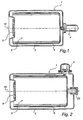
- a cleaning machine in the form of a laundry dry cleaning machine adapted to be used with liquefied carbon dioxide according to a first embodiment of the invention is shown.
- the cleaning machine comprises a fluid tight pressure vessel defined by a pressure vessel housing 1.
- the pressure vessel housing 1 includes a treatment compartment housing 2 defining a treatment compartment 3 and an driving unit compartment housing 4 defining an driving unit compartment 5.
- a drum 6 is rotatbly arranged in the treatment compartment 3.
- a driving arrangement including a motor 7 and a transmission arrangement 8, is connected to and operable to rotate the drum 6.
- the motor 7 is arranged in the driving unit compartment 5 and the transmission arrangement 8 extends from the motor 7 in the driving unit compartment 5 to the drum 6 in the treatment compartment 3.
- the treatment compartment housing 2 is provided with a laundry opening for loading/unloading the drum 6.
- the laundry opening is closable by a door 9 in a fluid and pressure tight manner.
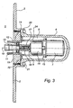
- the driving unit compartment 5 is connected to the treatment compartment 3 such that there is fluid communication between them.
- the fluid communication is realized by a fluid communication opening 11 at a rear end of the treatment compartment housing 2, which forms a passage for fluid between the treatment compartment 3 and the driving unit compartment 5.
- the fluid communication opening 11 is also a transmission opening through which the transmission arrangement 8 extends.
- a seat 19 is provided around the fluid communication opening 11 on the outside of the treatment compartment housing 2.
- the drum 6 is arranged to rotate about a horizontal ventral axis 10.
- a rotating shaft 13 of the drum 6 is supported in the fluid communication opening 11 by a bearing arrangement 12.
- the fluid communication opening 11 is located at approximately half the height of treatment compartment 3. Since the cleaning machine is adapted to operate with a level of carbon dioxide liquid up to one third of the height of treatment compartment 3, the fluid communication opening 11 is located above the maximal liquid level of the cleaning machine. Nevertheless, a sealing ring 14 is arranged in the fluid communication opening 11 for obstructing liquid flow but permitting gas flow between the treatment compartment 3 and the driving unit compartment 5.
- the driving unit compartment 5 and the treatment compartment 3, above the liquid level are filled with carbon dioxide gas and have essentially the same pressure.
- a cylindrical support structure 15 is attached to the treatment compartment housing 2 on the outside of the treatment compartment 3 beside the fluid communication opening 11 such that the support structure 15 surrounds the rim of the fluid communication opening 11.
- the support structure 15 is mounted to the treatment compartment housing 2 inside the driving unit compartment 5.
- the driving unit 7 is mounted to the free end of the support structure 15.
- a gearing arrangement 16, which is part of the transmission arrangement 8, is connected to the driving unit 7 and mounted to the inside of the cylindrical support structure 15.
- An output shaft 17 of the gearing arrangement 16 is connected to the rotating shaft 13 of the drum 6 by means of a shaft-coupling 18.
- the driving unit compartment housing 4 forms a protrusion centrally on the rear wall of the treatment compartment housing 2.
- the size of the driving unit compartment 5 is substantially less than the size of the treatment compartment 3.
- the driving unit compartment housing 4 has a hoodlike shape.
- the hoodlike driving unit compartment housing 4 comprises a cylindrical main body and a hemispherical distal end. Around a circular entrance opening at the proximal end, the hoodlike driving unit compartment housing 4 is provided with an outward facing circular flange 20.
- the circular flange 20 is removably connected to the seat 19 by bolts 21.
- a liquid and pressure tight sealing in the form of an O-ring 22 is arranged between the flange 20 and the seat 19.
- the driving unit 7 and the other parts of the driving arrangement that are arranged on the outside of the treatment compartment housing 2 are covered by the hoodlike, cylindrical driving unit compartment housing 4, which thus defines the driving unit compartment 5.
- the driving unit compartment housing 4 is positioned such that the axis of rotation 10 of the drum 6 is in line with the central axis of the cylindrical driving unit compartment housing 4.
- the round cylindrical shape of the driving unit compartment housing 4 is favourable with regard to withstanding the high pressure of a carbon dioxide cleaning machine.
- the cleaning machine includes a closing member comprising the entire driving unit compartment housing 4.
- the opening for accessing the driving unit compartment 5 corresponds to the delimitation of the driving unit compartment housing 4.
- the driving unit compartment 5 of the first embodiment of the invention can be accessed in the following way.
- the cleaning machine is emptied of the carbon dioxide fluid and the bolts 21 are unscrewed. Thereafter the closing member in form of the hoodlike driving unit compartment housing 4 is removed. Due to the limited size of the driving unit compartment 5, the driving unit compartment housing/closing member 4 has a weight of approximately 30 Kg. After the removal, the motor 7 is fully exposed and accessible from all sides except from the wall of the treatment compartment housing 2. Furthermore, the gearing arrangement 16 of the transmission arrangement 8 can be accessed through holes 24 in the support structure 15. Since the driving arrangement is supported in the fluid communication opening 11 and by the support structure 15, any service or repair work can be readily performed.
- the driving arrangement When the inspection is finished, the driving arrangement is inserted through the entrance opening of the closing member in form of the hoodlike driving unit compartment housing 4.
- the driving unit compartment housing 4 is then passed over the projecting parts of the driving arrangement and secured to the treatment compartment housing 2 by the bolts 21.
- the sealing 22 ensure the liquid and pressure tight closing of the pressure vessel housing 1.
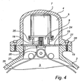
- Fig. 2 and 4 a second embodiment of the cleaning machine according to invention is shown.
- those components that correspond to components shown in Figs. 1 and 3 have the same reference numerals.
- the embodiment according to Figs. 2 and 4 differs from the first embodiment described above substantially only in that the driving unit compartment housing 4 is arranged protruding from the top side of the treatment compartment housing 2 at a rear end thereof and in the layout of the driving arrangement.
- the fluid communication between the driving unit compartment 5 the treatment compartment 3 is realized by a fluid communication opening 11 in the top wall of the treatment compartment housing 2.
- the fluid communication opening 11 is located as far as possible from the level of carbon dioxide liquid in the cleaning machine.
- the fluid communication opening 11 is also a transmission opening through which the transmission arrangement 8 extends.
- a cylindrical support structure 15 is attached to the treatment compartment housing 2 on the outside of the treatment compartment 3 over the fluid communication opening 11.
- the motor 7 is mounted to the support structure 15 at the driving unit compartment side thereof.
- An outgoing shaft 25 of the motor 7 is connected to an angle gear 26 being part of a transmission arrangement 8 by means of a shaft-coupling 18.
- the angle gear 26 is connected to the support structure 15 at the treatment compartment side thereof.
- the angle gear is connected to a belt driving arrangement 27.
- the belt 28 of the belt driving arrangement 27 is passed around the drum 6 for rotating the drum 6.
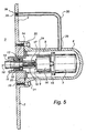
- Fig. 5 a third embodiment of the cleaning machine according to invention is shown.
- those components that correspond to components shown in Figs. 1 and 3 have the same reference numerals.
- the embodiment according to Fig. 5 differs from the first embodiment described above substantially only in that the fluid communication between the driving unit compartment 5 and the treatment compartment 3 is affected by a connection separate from the transmission opening 11.
- the fluid communication between the driving unit compartment 5 the treatment compartment 3 is realized by a fluid communication connection including a fluid communication opening 28 in the rear wall of the treatment compartment housing 2, a fluid communication opening 29 in the cylindrical wall of the driving unit compartment housing 4 and a duct 30 connecting the fluid communication openings 28, 29.
- the duct 30 is provided with a filter 31 at the fluid communication opening 28.
- a substantially fluid and pressure tight sealing 32 is provided in the transmission opening 11. Thus, it is possible to almost entirely prevent impurities to reach the driving unit compartment from the treatment compartment.
- the duct 32 in addition to the hoodlike driving unit compartment housing 4, the duct 32 has to be removed or at least disconnected from the driving unit compartment housing 4, when the driving unit compartment 5 is to be inspected.
- the duct is releasable attached to the treatment compartment housing 2 and the driving unit compartment housing 4 in a fluid and pressure tight manner.
Landscapes
- Engineering & Computer Science (AREA)
- Textile Engineering (AREA)
- Cleaning By Liquid Or Steam (AREA)
- Main Body Construction Of Washing Machines And Laundry Dryers (AREA)
- Electrical Discharge Machining, Electrochemical Machining, And Combined Machining (AREA)
- Confectionery (AREA)
- Extrusion Moulding Of Plastics Or The Like (AREA)
- Accessory Of Washing/Drying Machine, Commercial Washing/Drying Machine, Other Washing/Drying Machine (AREA)
Claims (17)
- Reinigungsmaschine, wie beispielsweise eine Wäschereinigungsmaschine, umfassend einen fluiddichten Druckbehälter, der durch ein Druckbehältergehäuse (1) definiert ist; wobei
das Druckbehältergehäuse (1) ein Behandlungsraumgehäuse (2), das einen Behandlungsraum (3) definiert, und ein Antriebseinheitsraumgehäuse (4) umfasst, das einen Antriebseinheitsraum (5) definiert und vom Behandlungsraumgehäuse (2) vorsteht;
der Antriebseinheitsraum (5) derart mit dem Behandlungsraum (3) verbunden ist, dass eine Fluidkommunikationsverbindung (8; 28, 29, 30) zwischen dem Antriebseinheitsraum (5) und dem Behandlungsraum (3) besteht, die so angeordnet ist, dass sie jegliche Druckunterschiede zwischen dem Antriebseinheitsraum (5) und dem Behandlungsraum (3) ausgleicht;
dadurch gekennzeichnet, dass das Druckbehältergehäuse (1) eine Öffnung zum Freilegen des Antriebseinheitsraums (5) und ein entfernbares Schließelement zum Schießen der Öffnung in einer fluid- und druckdichten Weise aufweist; und wobei
das Schließelement mindestens einen Abschnitt des Antriebseinheitsraumgehäuses (4) umfasst, derart dass, wenn das Schließelement entfernt wird, der Antriebseinheitsraum (5) von außerhalb des Behandlungsraums (3) zugänglich ist. - Reinigungsmaschine nach Anspruch 1, wobei das Behandlungsraumgehäuse (2) eine vordere Wand, eine hintere Wand und Seitenwände aufweist; und wobei das Antriebseinheitsraumgehäuse (4) mit einer Wand des Behandlungsraumgehäuses (2) derart verbunden ist, dass das Antriebseinheitsraumgehäuse (4) weniger als die Hälfte der Ausdehnung der einen Wand abdeckt.
- Reinigungsmaschine nach Anspruch 1 oder 2, wobei das Antriebseinheitsraumgehäuse (4) eine haubenähnliche Form aufweist, und das Schließelement das haubenähnliche Antriebseinheitsraumgehäuse (4) derart umfasst, dass, wenn das Schließelement entfernt wird, das Innere der Antriebseinheitsraums (5) völlig unbedeckt ist, um uneingeschränktem Zugang zu jeglichen Elementen darin zu ermöglichen.
- Reinigungsmaschine nach Anspruch 3, wobei das haubenähnliche Antriebseinheitsraumgehäuse (4) eine Eintrittsöffnung aufweist, und wobei das Schließelement, welches das haubenähnliche Antriebseinheitsraumgehäuse (4) umfasst, abnehmbar am Behandlungsraumgehäuse (2) befestigt ist, wobei die Eintrittsöffnung dem Behandlungsraumgehäuse (4) gegenüberliegt.
- Reinigungsmaschine nach einem der Ansprüche 1 bis 4, wobei die Fluidkommunikationsverbindung (11), die zwischen dem Behandlungsraum (3) und dem Antriebseinheitsraum (5) angeordnet ist, durch eine Übertragungsöffnung realisiert ist, die vom Behandlungsraum (3) durch das Behandlungsraumgehäuse (2) und das Antriebseinheitsraumgehäuse (4) zum Antriebseinheitsraum (5) verläuft.
- Reinigungsmaschine nach Anspruch 5, wobei die Übertragungsöffnung mit einer Abschirmungseinrichtung (15) zum Reduzieren von Flüssigkeitskommunikation zwischen dem Behandlungsraum (3) und dem Antriebseinheitsraum (5) versehen ist.
- Reinigungsmaschine nach einem der Ansprüche 1 bis 4, wobei die Fluidkommunikationsverbindung (28, 29, 30), die zwischen dem Antriebseinheitsraum (5) und dem Behandlungsraum (3) angeordnet ist, durch einen Kanal (30) realisiert ist, der zwischen dem Behandlungsraum (3) und dem Antriebseinheitsraum (5) angeschlossen ist.
- Reinigungsmaschine nach einem der Anspruch 7, wobei eine Übertragungsöffnung zwischen dem Antriebseinheitsraum (5) und dem Behandlungsraum (3) vorgesehen ist, und eine Dichtung (32) in der Übertragungsöffnung angeordnet ist, um die Fluidkommunikation zwischen dem Behandlungsraum (3) und dem Antriebseinheitsraum (5) durch die Übertragungsöffnung zu hemmen.
- Reinigungsmaschine nach Anspruch 7 oder 8, wobei ein Filter (31) im Kanal (30) vorgesehen ist.
- Reinigungsmaschine nach einem der Ansprüche 5 bis 9, wobei
eine Trommel (6) zur Aufnahme von zu reinigenden Objekten und eine Antriebsanordnung (7, 8) im Druckbehälter angeordnet sind;
die Trommel (6) drehbar im Behandlungsraum (3) angeordnet ist;
die Antriebsanordnung (7, 8) wenigstens teilweise im Antriebseinheitsraum (5) angeordnet ist; und wobei
die Antriebsanordnung (7, 8) mit der Trommel (6) verbunden ist und betrieben werden kann, um die Trommel (6) zu drehen. - Reinigungsmaschine nach Anspruch 4 und 10, wobei sich die Antriebsanordnung (7, 8) vom Antriebseinheitsraum (5) durch die Übertragungsöffnung in den Behandlungsraum (3) erstreckt; und wobei das Schließelement, welches das haubenähnliche Antriebseinheitsraumgehäuse (4) umfasst, um den Rand der Übertragungsöffnung am Behandlungsraumgehäuse (2) befestigt ist, wobei die Eintrittsöffnung der Übertragungsöffnung gegenüberliegt.
- Reinigungsmaschine nach Anspruch 11, wobei eine Trägerstruktur (15) innerhalb des Antriebseinheitsraums (5) vorgesehen ist, die wenigstens an einer Seite der Übertragungsöffnung am Behandlungsraumgehäuse (2) montiert ist.
- Reinigungsmaschine nach Anspruch 12, wobei ein Motor (7) der Antriebsanordnung (7, 8) an der Trägerstruktur (15) montiert ist.
- Reinigungsmaschine nach Anspruch 12 oder 13, wobei eine Übertragungsanordnung (8) der Antriebsanordnung (7, 8) an der Trägerstruktur (15) montiert ist.
- Reinigungsmaschine nach einem der Ansprüche 10 bis 14, wobei die Trommel (6) um eine Achse (10) drehbar ist, und wobei das Antriebseinheitsraumgehäuse (4) derart angeordnet ist, dass die Antriebsanordnung (7, 8) mit der Achse (10) ausgerichtet ist.
- Reinigungsmaschine nach einem der Ansprüche 10 bis 15, wobei die Trommel (6) um eine im Wesentlichen horizontale Achse drehbar ist.
- Reinigungsmaschine nach einem der Ansprüche 1 bis 16, wobei die Fluidkommunikationsverbindung (11; 28, 29, 30), zwischen dem Antriebseinheitsraum (5) und dem Behandlungsraum (3) über 1/3 der Höhe des Behandlungsraums (3) erfolgt.
Applications Claiming Priority (3)
| Application Number | Priority Date | Filing Date | Title |
|---|---|---|---|
| SE0600798 | 2006-04-10 | ||
| US11/445,779 US7841216B2 (en) | 2006-04-10 | 2006-06-02 | Dry cleaning machine and driving unit compartment |
| PCT/SE2007/000260 WO2007117192A1 (en) | 2006-04-10 | 2007-03-15 | Cleaning machine |
Publications (2)
| Publication Number | Publication Date |
|---|---|
| EP2010707A1 EP2010707A1 (de) | 2009-01-07 |
| EP2010707B1 true EP2010707B1 (de) | 2010-12-29 |
Family
ID=38788547
Family Applications (1)
| Application Number | Title | Priority Date | Filing Date |
|---|---|---|---|
| EP07716071A Not-in-force EP2010707B1 (de) | 2006-04-10 | 2007-03-15 | Reinigungsmaschine |
Country Status (5)
| Country | Link |
|---|---|
| US (1) | US7841216B2 (de) |
| EP (1) | EP2010707B1 (de) |
| AT (1) | ATE493538T1 (de) |
| DE (1) | DE602007011593D1 (de) |
| WO (1) | WO2007117192A1 (de) |
Families Citing this family (10)
| Publication number | Priority date | Publication date | Assignee | Title |
|---|---|---|---|---|
| US9091017B2 (en) * | 2012-01-17 | 2015-07-28 | Co2Nexus, Inc. | Barrier densified fluid cleaning system |
| KR102460179B1 (ko) * | 2020-11-17 | 2022-10-28 | 엘지전자 주식회사 | 의류처리장치 및 그 제어방법 |
| KR102460178B1 (ko) | 2020-11-17 | 2022-10-28 | 엘지전자 주식회사 | 세탁기 |
| KR102503951B1 (ko) | 2021-01-25 | 2023-02-27 | 엘지전자 주식회사 | 세탁기 |
| KR102536873B1 (ko) * | 2021-01-25 | 2023-05-26 | 엘지전자 주식회사 | 세탁기 |
| KR102552904B1 (ko) | 2021-01-25 | 2023-07-07 | 엘지전자 주식회사 | 세탁기 |
| KR102472995B1 (ko) * | 2021-01-25 | 2022-12-01 | 엘지전자 주식회사 | 세탁기 |
| KR102536872B1 (ko) * | 2021-01-25 | 2023-05-26 | 엘지전자 주식회사 | 세탁기 |
| CN220529917U (zh) | 2023-05-24 | 2024-02-27 | 派尼尔股份有限公司 | 一种多功能清洗机 |
| CN220675913U (zh) | 2023-06-01 | 2024-03-29 | 派尼尔股份有限公司 | 一种多功能清洗机 |
Family Cites Families (10)
| Publication number | Priority date | Publication date | Assignee | Title |
|---|---|---|---|---|
| US2539407A (en) | 1947-02-21 | 1951-01-30 | Detrex Corp | Solvent saver recovery apparatus |
| GB2261828B (en) * | 1991-11-27 | 1995-08-23 | Barry Raymond Sherratt | Water conditioning device |
| JPH1128298A (ja) | 1997-07-11 | 1999-02-02 | Toshiba Corp | ドラム式洗濯機 |
| US6098430A (en) * | 1998-03-24 | 2000-08-08 | Micell Technologies, Inc. | Cleaning apparatus |
| US6351973B1 (en) * | 1999-02-04 | 2002-03-05 | Micell Technologies, Inc. | Internal motor drive liquid carbon dioxide agitation system |
| KR100415024B1 (ko) * | 1999-03-10 | 2004-01-13 | 가부시끼가이샤 도시바 | 드럼식 세탁기 |
| DE19922610A1 (de) * | 1999-05-17 | 2000-11-23 | Bsh Bosch Siemens Hausgeraete | Antriebsvorrichtung für eine Waschmaschine |
| US6460382B1 (en) * | 1999-10-18 | 2002-10-08 | Lg Electronics Inc. | Structure of driving unit in drum type washing machine |
| SE516623C2 (sv) * | 2000-06-15 | 2002-02-05 | Electrolux Ab | Säkerhetsanordning vid en tvättmaskinslucka |
| US6484738B1 (en) * | 2000-11-21 | 2002-11-26 | Tca, Inc. | Dishwashing machine with convenient pump/motor access |
-
2006
- 2006-06-02 US US11/445,779 patent/US7841216B2/en active Active
-
2007
- 2007-03-15 DE DE602007011593T patent/DE602007011593D1/de active Active
- 2007-03-15 AT AT07716071T patent/ATE493538T1/de not_active IP Right Cessation
- 2007-03-15 EP EP07716071A patent/EP2010707B1/de not_active Not-in-force
- 2007-03-15 WO PCT/SE2007/000260 patent/WO2007117192A1/en not_active Ceased
Also Published As
| Publication number | Publication date |
|---|---|
| WO2007117192A1 (en) | 2007-10-18 |
| US20070277562A1 (en) | 2007-12-06 |
| DE602007011593D1 (de) | 2011-02-10 |
| EP2010707A1 (de) | 2009-01-07 |
| ATE493538T1 (de) | 2011-01-15 |
| US7841216B2 (en) | 2010-11-30 |
Similar Documents
| Publication | Publication Date | Title |
|---|---|---|
| EP2010707B1 (de) | Reinigungsmaschine | |
| CN105231908B (zh) | 食物处理装置 | |
| CN107059348B (zh) | 洗衣机 | |
| RU2601932C2 (ru) | Моечный аппарат высокого давления | |
| EP3056599B1 (de) | Kleidungsbehandlungsvorrichtung | |
| KR101590012B1 (ko) | 의류처리장치 | |
| CN215348521U (zh) | 一种食品加工机 | |
| US2404450A (en) | Washing machine | |
| CN110387693B (zh) | 洗衣机 | |
| CN112955058A (zh) | 手持式真空吸尘器 | |
| CN106319858B (zh) | 衣物处理装置 | |
| CN111373086B (zh) | 洗衣干衣机 | |
| JP2758140B2 (ja) | リファイナのディスクの着脱方法 | |
| CN201162132Y (zh) | 具有紧急排空软管的洗衣机 | |
| US2099163A (en) | Combined washing and drying machine | |
| CN212594635U (zh) | 一种废气处理装置 | |
| CN223640518U (zh) | 一种烹饪设备 | |
| CN216661840U (zh) | 无心车床出料防尘组件 | |
| CN120099764A (zh) | 衣物处理装置 | |
| JP7456327B2 (ja) | 船舶推進機のエンジン | |
| JP2009274029A (ja) | マイクロ波生ゴミ処理機 | |
| KR20070090397A (ko) | 세탁기의 필터 | |
| CN110607655B (zh) | 滚筒洗衣机及其内筒组件 | |
| JP2023069167A (ja) | 洗米装置 | |
| JPS6036817B2 (ja) | 湿式自動粉砕装置 |
Legal Events
| Date | Code | Title | Description |
|---|---|---|---|
| PUAI | Public reference made under article 153(3) epc to a published international application that has entered the european phase |
Free format text: ORIGINAL CODE: 0009012 |
|
| 17P | Request for examination filed |
Effective date: 20081110 |
|
| AK | Designated contracting states |
Kind code of ref document: A1 Designated state(s): AT BE BG CH CY CZ DE DK EE ES FI FR GB GR HU IE IS IT LI LT LU LV MC MT NL PL PT RO SE SI SK TR |
|
| AX | Request for extension of the european patent |
Extension state: AL BA HR MK RS |
|
| 17Q | First examination report despatched |
Effective date: 20090608 |
|
| GRAP | Despatch of communication of intention to grant a patent |
Free format text: ORIGINAL CODE: EPIDOSNIGR1 |
|
| DAX | Request for extension of the european patent (deleted) | ||
| GRAS | Grant fee paid |
Free format text: ORIGINAL CODE: EPIDOSNIGR3 |
|
| GRAA | (expected) grant |
Free format text: ORIGINAL CODE: 0009210 |
|
| AK | Designated contracting states |
Kind code of ref document: B1 Designated state(s): AT BE BG CH CY CZ DE DK EE ES FI FR GB GR HU IE IS IT LI LT LU LV MC MT NL PL PT RO SE SI SK TR |
|
| REG | Reference to a national code |
Ref country code: GB Ref legal event code: FG4D |
|
| REG | Reference to a national code |
Ref country code: CH Ref legal event code: EP |
|
| REG | Reference to a national code |
Ref country code: IE Ref legal event code: FG4D |
|
| REF | Corresponds to: |
Ref document number: 602007011593 Country of ref document: DE Date of ref document: 20110210 Kind code of ref document: P |
|
| REG | Reference to a national code |
Ref country code: DE Ref legal event code: R096 Ref document number: 602007011593 Country of ref document: DE Effective date: 20110210 |
|
| REG | Reference to a national code |
Ref country code: SE Ref legal event code: TRGR |
|
| REG | Reference to a national code |
Ref country code: NL Ref legal event code: T3 |
|
| PG25 | Lapsed in a contracting state [announced via postgrant information from national office to epo] |
Ref country code: LT Free format text: LAPSE BECAUSE OF FAILURE TO SUBMIT A TRANSLATION OF THE DESCRIPTION OR TO PAY THE FEE WITHIN THE PRESCRIBED TIME-LIMIT Effective date: 20101229 |
|
| LTIE | Lt: invalidation of european patent or patent extension |
Effective date: 20101229 |
|
| PG25 | Lapsed in a contracting state [announced via postgrant information from national office to epo] |
Ref country code: AT Free format text: LAPSE BECAUSE OF FAILURE TO SUBMIT A TRANSLATION OF THE DESCRIPTION OR TO PAY THE FEE WITHIN THE PRESCRIBED TIME-LIMIT Effective date: 20101229 Ref country code: SI Free format text: LAPSE BECAUSE OF FAILURE TO SUBMIT A TRANSLATION OF THE DESCRIPTION OR TO PAY THE FEE WITHIN THE PRESCRIBED TIME-LIMIT Effective date: 20101229 Ref country code: FI Free format text: LAPSE BECAUSE OF FAILURE TO SUBMIT A TRANSLATION OF THE DESCRIPTION OR TO PAY THE FEE WITHIN THE PRESCRIBED TIME-LIMIT Effective date: 20101229 Ref country code: CY Free format text: LAPSE BECAUSE OF FAILURE TO SUBMIT A TRANSLATION OF THE DESCRIPTION OR TO PAY THE FEE WITHIN THE PRESCRIBED TIME-LIMIT Effective date: 20101229 Ref country code: BG Free format text: LAPSE BECAUSE OF FAILURE TO SUBMIT A TRANSLATION OF THE DESCRIPTION OR TO PAY THE FEE WITHIN THE PRESCRIBED TIME-LIMIT Effective date: 20110329 Ref country code: LV Free format text: LAPSE BECAUSE OF FAILURE TO SUBMIT A TRANSLATION OF THE DESCRIPTION OR TO PAY THE FEE WITHIN THE PRESCRIBED TIME-LIMIT Effective date: 20101229 |
|
| PG25 | Lapsed in a contracting state [announced via postgrant information from national office to epo] |
Ref country code: EE Free format text: LAPSE BECAUSE OF FAILURE TO SUBMIT A TRANSLATION OF THE DESCRIPTION OR TO PAY THE FEE WITHIN THE PRESCRIBED TIME-LIMIT Effective date: 20101229 Ref country code: CZ Free format text: LAPSE BECAUSE OF FAILURE TO SUBMIT A TRANSLATION OF THE DESCRIPTION OR TO PAY THE FEE WITHIN THE PRESCRIBED TIME-LIMIT Effective date: 20101229 Ref country code: PT Free format text: LAPSE BECAUSE OF FAILURE TO SUBMIT A TRANSLATION OF THE DESCRIPTION OR TO PAY THE FEE WITHIN THE PRESCRIBED TIME-LIMIT Effective date: 20110429 Ref country code: GR Free format text: LAPSE BECAUSE OF FAILURE TO SUBMIT A TRANSLATION OF THE DESCRIPTION OR TO PAY THE FEE WITHIN THE PRESCRIBED TIME-LIMIT Effective date: 20110330 Ref country code: ES Free format text: LAPSE BECAUSE OF FAILURE TO SUBMIT A TRANSLATION OF THE DESCRIPTION OR TO PAY THE FEE WITHIN THE PRESCRIBED TIME-LIMIT Effective date: 20110409 Ref country code: IS Free format text: LAPSE BECAUSE OF FAILURE TO SUBMIT A TRANSLATION OF THE DESCRIPTION OR TO PAY THE FEE WITHIN THE PRESCRIBED TIME-LIMIT Effective date: 20110429 Ref country code: BE Free format text: LAPSE BECAUSE OF FAILURE TO SUBMIT A TRANSLATION OF THE DESCRIPTION OR TO PAY THE FEE WITHIN THE PRESCRIBED TIME-LIMIT Effective date: 20101229 |
|
| PG25 | Lapsed in a contracting state [announced via postgrant information from national office to epo] |
Ref country code: PL Free format text: LAPSE BECAUSE OF FAILURE TO SUBMIT A TRANSLATION OF THE DESCRIPTION OR TO PAY THE FEE WITHIN THE PRESCRIBED TIME-LIMIT Effective date: 20101229 Ref country code: SK Free format text: LAPSE BECAUSE OF FAILURE TO SUBMIT A TRANSLATION OF THE DESCRIPTION OR TO PAY THE FEE WITHIN THE PRESCRIBED TIME-LIMIT Effective date: 20101229 Ref country code: RO Free format text: LAPSE BECAUSE OF FAILURE TO SUBMIT A TRANSLATION OF THE DESCRIPTION OR TO PAY THE FEE WITHIN THE PRESCRIBED TIME-LIMIT Effective date: 20101229 |
|
| PG25 | Lapsed in a contracting state [announced via postgrant information from national office to epo] |
Ref country code: DK Free format text: LAPSE BECAUSE OF FAILURE TO SUBMIT A TRANSLATION OF THE DESCRIPTION OR TO PAY THE FEE WITHIN THE PRESCRIBED TIME-LIMIT Effective date: 20101229 Ref country code: MC Free format text: LAPSE BECAUSE OF NON-PAYMENT OF DUE FEES Effective date: 20110331 |
|
| REG | Reference to a national code |
Ref country code: CH Ref legal event code: PL |
|
| PLBE | No opposition filed within time limit |
Free format text: ORIGINAL CODE: 0009261 |
|
| STAA | Information on the status of an ep patent application or granted ep patent |
Free format text: STATUS: NO OPPOSITION FILED WITHIN TIME LIMIT |
|
| 26N | No opposition filed |
Effective date: 20110930 |
|
| PG25 | Lapsed in a contracting state [announced via postgrant information from national office to epo] |
Ref country code: MT Free format text: LAPSE BECAUSE OF FAILURE TO SUBMIT A TRANSLATION OF THE DESCRIPTION OR TO PAY THE FEE WITHIN THE PRESCRIBED TIME-LIMIT Effective date: 20101229 |
|
| REG | Reference to a national code |
Ref country code: IE Ref legal event code: MM4A |
|
| REG | Reference to a national code |
Ref country code: DE Ref legal event code: R097 Ref document number: 602007011593 Country of ref document: DE Effective date: 20110930 |
|
| PG25 | Lapsed in a contracting state [announced via postgrant information from national office to epo] |
Ref country code: IE Free format text: LAPSE BECAUSE OF NON-PAYMENT OF DUE FEES Effective date: 20110315 Ref country code: LI Free format text: LAPSE BECAUSE OF NON-PAYMENT OF DUE FEES Effective date: 20110331 Ref country code: CH Free format text: LAPSE BECAUSE OF NON-PAYMENT OF DUE FEES Effective date: 20110331 |
|
| PG25 | Lapsed in a contracting state [announced via postgrant information from national office to epo] |
Ref country code: IT Free format text: LAPSE BECAUSE OF FAILURE TO SUBMIT A TRANSLATION OF THE DESCRIPTION OR TO PAY THE FEE WITHIN THE PRESCRIBED TIME-LIMIT Effective date: 20101229 |
|
| PG25 | Lapsed in a contracting state [announced via postgrant information from national office to epo] |
Ref country code: LU Free format text: LAPSE BECAUSE OF NON-PAYMENT OF DUE FEES Effective date: 20110315 |
|
| PG25 | Lapsed in a contracting state [announced via postgrant information from national office to epo] |
Ref country code: TR Free format text: LAPSE BECAUSE OF FAILURE TO SUBMIT A TRANSLATION OF THE DESCRIPTION OR TO PAY THE FEE WITHIN THE PRESCRIBED TIME-LIMIT Effective date: 20101229 |
|
| PG25 | Lapsed in a contracting state [announced via postgrant information from national office to epo] |
Ref country code: HU Free format text: LAPSE BECAUSE OF FAILURE TO SUBMIT A TRANSLATION OF THE DESCRIPTION OR TO PAY THE FEE WITHIN THE PRESCRIBED TIME-LIMIT Effective date: 20101229 |
|
| REG | Reference to a national code |
Ref country code: FR Ref legal event code: PLFP Year of fee payment: 10 |
|
| REG | Reference to a national code |
Ref country code: FR Ref legal event code: PLFP Year of fee payment: 11 |
|
| REG | Reference to a national code |
Ref country code: FR Ref legal event code: PLFP Year of fee payment: 12 |
|
| REG | Reference to a national code |
Ref country code: DE Ref legal event code: R081 Ref document number: 602007011593 Country of ref document: DE Owner name: ELECTROLUX PROFESSIONAL AB, SE Free format text: FORMER OWNER: AKTIEBOLAGET ELECTROLUX, STOCKHOLM, SE |
|
| REG | Reference to a national code |
Ref country code: NL Ref legal event code: PD Owner name: ELECTROLUX PROFESSIONAL AB; SE Free format text: DETAILS ASSIGNMENT: CHANGE OF OWNER(S), ASSIGNMENT; FORMER OWNER NAME: AKTIEBOLAGET ELECTROLUX Effective date: 20200306 |
|
| REG | Reference to a national code |
Ref country code: GB Ref legal event code: 732E Free format text: REGISTERED BETWEEN 20200312 AND 20200318 |
|
| P01 | Opt-out of the competence of the unified patent court (upc) registered |
Effective date: 20230526 |
|
| PGFP | Annual fee paid to national office [announced via postgrant information from national office to epo] |
Ref country code: NL Payment date: 20240221 Year of fee payment: 18 |
|
| PGFP | Annual fee paid to national office [announced via postgrant information from national office to epo] |
Ref country code: DE Payment date: 20240216 Year of fee payment: 18 Ref country code: GB Payment date: 20240215 Year of fee payment: 18 |
|
| PGFP | Annual fee paid to national office [announced via postgrant information from national office to epo] |
Ref country code: SE Payment date: 20240215 Year of fee payment: 18 Ref country code: FR Payment date: 20240215 Year of fee payment: 18 |
|
| REG | Reference to a national code |
Ref country code: DE Ref legal event code: R119 Ref document number: 602007011593 Country of ref document: DE |
|
| REG | Reference to a national code |
Ref country code: SE Ref legal event code: EUG |
|
| REG | Reference to a national code |
Ref country code: NL Ref legal event code: MM Effective date: 20250401 |
|
| GBPC | Gb: european patent ceased through non-payment of renewal fee |
Effective date: 20250315 |
|
| PG25 | Lapsed in a contracting state [announced via postgrant information from national office to epo] |
Ref country code: NL Free format text: LAPSE BECAUSE OF NON-PAYMENT OF DUE FEES Effective date: 20250401 |
|
| PG25 | Lapsed in a contracting state [announced via postgrant information from national office to epo] |
Ref country code: DE Free format text: LAPSE BECAUSE OF NON-PAYMENT OF DUE FEES Effective date: 20251001 |
|
| PG25 | Lapsed in a contracting state [announced via postgrant information from national office to epo] |
Ref country code: GB Free format text: LAPSE BECAUSE OF NON-PAYMENT OF DUE FEES Effective date: 20250315 |
|
| PG25 | Lapsed in a contracting state [announced via postgrant information from national office to epo] |
Ref country code: FR Free format text: LAPSE BECAUSE OF NON-PAYMENT OF DUE FEES Effective date: 20250331 |
|
| PG25 | Lapsed in a contracting state [announced via postgrant information from national office to epo] |
Ref country code: SE Free format text: LAPSE BECAUSE OF NON-PAYMENT OF DUE FEES Effective date: 20250316 |