EP2010682B1 - Vorrichtung und verfahren zur dynamischen steuerung von kombinierten brennern und lanzen zum einblasen von sauerstoff in einen ofen - Google Patents
Vorrichtung und verfahren zur dynamischen steuerung von kombinierten brennern und lanzen zum einblasen von sauerstoff in einen ofen Download PDFInfo
- Publication number
- EP2010682B1 EP2010682B1 EP20070719198 EP07719198A EP2010682B1 EP 2010682 B1 EP2010682 B1 EP 2010682B1 EP 20070719198 EP20070719198 EP 20070719198 EP 07719198 A EP07719198 A EP 07719198A EP 2010682 B1 EP2010682 B1 EP 2010682B1
- Authority
- EP
- European Patent Office
- Prior art keywords
- nozzle
- axis
- burner
- oxygen
- pipe
- Prior art date
- Legal status (The legal status is an assumption and is not a legal conclusion. Google has not performed a legal analysis and makes no representation as to the accuracy of the status listed.)
- Not-in-force
Links
Images


Classifications
-
- F—MECHANICAL ENGINEERING; LIGHTING; HEATING; WEAPONS; BLASTING
- F27—FURNACES; KILNS; OVENS; RETORTS
- F27B—FURNACES, KILNS, OVENS OR RETORTS IN GENERAL; OPEN SINTERING OR LIKE APPARATUS
- F27B3/00—Hearth-type furnaces, e.g. of reverberatory type; Electric arc furnaces ; Tank furnaces
- F27B3/10—Details, accessories or equipment, e.g. dust-collectors, specially adapted for hearth-type furnaces
- F27B3/20—Arrangements of heating devices
- F27B3/205—Burners
-
- C—CHEMISTRY; METALLURGY
- C21—METALLURGY OF IRON
- C21C—PROCESSING OF PIG-IRON, e.g. REFINING, MANUFACTURE OF WROUGHT-IRON OR STEEL; TREATMENT IN MOLTEN STATE OF FERROUS ALLOYS
- C21C5/00—Manufacture of carbon-steel, e.g. plain mild steel, medium carbon steel or cast steel or stainless steel
- C21C5/52—Manufacture of steel in electric furnaces
- C21C5/5211—Manufacture of steel in electric furnaces in an alternating current [AC] electric arc furnace
- C21C5/5217—Manufacture of steel in electric furnaces in an alternating current [AC] electric arc furnace equipped with burners or devices for injecting gas, i.e. oxygen, or pulverulent materials into the furnace
-
- F—MECHANICAL ENGINEERING; LIGHTING; HEATING; WEAPONS; BLASTING
- F27—FURNACES; KILNS; OVENS; RETORTS
- F27B—FURNACES, KILNS, OVENS OR RETORTS IN GENERAL; OPEN SINTERING OR LIKE APPARATUS
- F27B3/00—Hearth-type furnaces, e.g. of reverberatory type; Electric arc furnaces ; Tank furnaces
- F27B3/08—Hearth-type furnaces, e.g. of reverberatory type; Electric arc furnaces ; Tank furnaces heated electrically, with or without any other source of heat
- F27B3/085—Arc furnaces
-
- F—MECHANICAL ENGINEERING; LIGHTING; HEATING; WEAPONS; BLASTING
- F27—FURNACES; KILNS; OVENS; RETORTS
- F27B—FURNACES, KILNS, OVENS OR RETORTS IN GENERAL; OPEN SINTERING OR LIKE APPARATUS
- F27B3/00—Hearth-type furnaces, e.g. of reverberatory type; Electric arc furnaces ; Tank furnaces
- F27B3/10—Details, accessories or equipment, e.g. dust-collectors, specially adapted for hearth-type furnaces
- F27B3/22—Arrangements of air or gas supply devices
- F27B3/225—Oxygen blowing
-
- F—MECHANICAL ENGINEERING; LIGHTING; HEATING; WEAPONS; BLASTING
- F27—FURNACES; KILNS; OVENS; RETORTS
- F27B—FURNACES, KILNS, OVENS OR RETORTS IN GENERAL; OPEN SINTERING OR LIKE APPARATUS
- F27B3/00—Hearth-type furnaces, e.g. of reverberatory type; Electric arc furnaces ; Tank furnaces
- F27B3/10—Details, accessories or equipment, e.g. dust-collectors, specially adapted for hearth-type furnaces
- F27B3/28—Arrangement of controlling, monitoring, alarm or the like devices
-
- F—MECHANICAL ENGINEERING; LIGHTING; HEATING; WEAPONS; BLASTING
- F27—FURNACES; KILNS; OVENS; RETORTS
- F27D—DETAILS OR ACCESSORIES OF FURNACES, KILNS, OVENS OR RETORTS, IN SO FAR AS THEY ARE OF KINDS OCCURRING IN MORE THAN ONE KIND OF FURNACE
- F27D19/00—Arrangements of controlling devices
-
- F—MECHANICAL ENGINEERING; LIGHTING; HEATING; WEAPONS; BLASTING
- F27—FURNACES; KILNS; OVENS; RETORTS
- F27D—DETAILS OR ACCESSORIES OF FURNACES, KILNS, OVENS OR RETORTS, IN SO FAR AS THEY ARE OF KINDS OCCURRING IN MORE THAN ONE KIND OF FURNACE
- F27D21/00—Arrangement of monitoring devices; Arrangement of safety devices
-
- F—MECHANICAL ENGINEERING; LIGHTING; HEATING; WEAPONS; BLASTING
- F27—FURNACES; KILNS; OVENS; RETORTS
- F27D—DETAILS OR ACCESSORIES OF FURNACES, KILNS, OVENS OR RETORTS, IN SO FAR AS THEY ARE OF KINDS OCCURRING IN MORE THAN ONE KIND OF FURNACE
- F27D3/00—Charging; Discharging; Manipulation of charge
- F27D3/16—Introducing a fluid jet or current into the charge
-
- F—MECHANICAL ENGINEERING; LIGHTING; HEATING; WEAPONS; BLASTING
- F27—FURNACES; KILNS; OVENS; RETORTS
- F27D—DETAILS OR ACCESSORIES OF FURNACES, KILNS, OVENS OR RETORTS, IN SO FAR AS THEY ARE OF KINDS OCCURRING IN MORE THAN ONE KIND OF FURNACE
- F27D3/00—Charging; Discharging; Manipulation of charge
- F27D3/18—Charging particulate material using a fluid carrier
-
- Y—GENERAL TAGGING OF NEW TECHNOLOGICAL DEVELOPMENTS; GENERAL TAGGING OF CROSS-SECTIONAL TECHNOLOGIES SPANNING OVER SEVERAL SECTIONS OF THE IPC; TECHNICAL SUBJECTS COVERED BY FORMER USPC CROSS-REFERENCE ART COLLECTIONS [XRACs] AND DIGESTS
- Y02—TECHNOLOGIES OR APPLICATIONS FOR MITIGATION OR ADAPTATION AGAINST CLIMATE CHANGE
- Y02P—CLIMATE CHANGE MITIGATION TECHNOLOGIES IN THE PRODUCTION OR PROCESSING OF GOODS
- Y02P10/00—Technologies related to metal processing
- Y02P10/20—Recycling
Definitions
- the present invention relates to a device for dynamically controlling combined burners and oxygen blast lances in a metallurgical furnace, such as an electric arc furnace or a reduction furnace for improving or optimizing its energy efficiency.
- a combi burner is a preheating burner associated with an oxygen blast lance.
- the invention also relates to the method of implementation of the device.
- an electric arc furnace such as those used for example in metallurgy, hereinafter succinctly called “arc furnace”
- arc furnace often has several burners, generally arranged on the side wall of the furnace.
- the load of such an arc furnace is mainly composed of metal waste that may contain decommissioned parts or debris of cast iron, steel or ferrous or non-ferrous metals, which will be in the following description Indistinctly called “grape (s)” or “scrap (s)".
- oxy-fuel burners alone or combined burners are used, including the combination of an oxy-fuel burner for preheating and an oxygen blast lance. either lances with oxygen insufflation alone or these various devices in combination. More generally, these devices can also equip metallurgical melting vessels, of "smelting reduction" type. All these metallurgical vessels may also be provided with material blast lances (eg coal, lime, ore, dust, etc.).
- material blast lances eg coal, lime, ore, dust, etc.
- the Applicant has proposed a device for the dynamic control of the combustion of a gaseous or liquid fuel burner in an electric arc furnace, in particular in a steel arc furnace, the burner emitting in use a flame by an opening located at one of its ends above a bath of molten metal itself surmounted by a load of grape.
- This device comprises non-contact measuring means, located outside the arc furnace, for estimating the distance between the end of the burner and a target constituted by solid scrap located opposite said end.
- These measuring means comprise a source emitting a signal passing inside the burner towards said target, and a detector where said signal reflected by the target is captured, also passing inside the burner, and preferably, an optical distance sensor type sensing head, located inside or at the rear of the burner, having for example a pulsed laser emitting an incident beam aimed at the scrap through an opening located in the axis of the burner and a photodetector adapted to receive the laser beam reflected by the shot.
- This device could advantageously be implemented either in the case of a separate burner, or in the case of a combi burner as defined above, or in the case of an oxygen insufflation lance alone.
- Dynamic control is a real-time control or regulation that takes into account operational conditions at a given time, as opposed to a preprogrammed operating point.
- the dynamic control device developed for the oxy-fuel burners could thus find a very interesting application also in the case of the use of oxygen lances and combined burners in a metallurgical melting vessel.
- the difficulty of using this device in this case lies in the small diameter of the oxygen tuyeres (typically 18-30 mm). Indeed, the device described above operates with large beam widths and distinct and convergent optical paths, incompatible with the aforementioned nozzle diameter values.
- the patent application DE 27 45 251 A1 discloses a device for dynamically controlling the distance between the end of an oxygen lance and a bath of molten metal in an oven, more particularly in a converter. A distance measurement, according to the time of flight method, is performed without contact via a device placed outside the oven on another end of the lance. This device is equipped with a transmitting source such as a pulsed laser and a detector where is captured the beam reflected by the bath.
- a transmitting source such as a pulsed laser
- detector where is captured the beam reflected by the bath.
- the patent application DE 20 45 602 A1 describes a radar system for the automatic control of the distance between the end of an oxygen lance and the surface of a molten bath.
- a generator placed outside the furnace transmits a pulsed electromagnetic signal through the lance to the bath surface and the reflected signal then passes through the lance back to a receiver. The time elapsed between the transmission and the reflection makes it possible to calculate the distance between the lance and the bath.
- an optical measuring device retractable in a protective housing and integral with the handling system of an oxygen lance in an oxygen converter.
- This measuring device comprises a head laser optical device capable of sending an incident beam on a target zone in the furnace, such as the slag surface, to receive and detect the reflected beam and to determine, by comparison of the two beams, the distance to which the target zone is located .
- This device is only intended to allow a correct adjustment of the distance separating the slag from the head of the oxygen lance.
- the present invention aims to propose a solution that makes it possible to overcome the drawbacks of the state of the art.
- the present invention aims to provide a method of dynamic control, that is to say during operation, lances oxygen blowing or injection of pressurized materials mounted on the walls of metallurgical furnaces or to "smelting reduction".
- An additional aim of the invention is to improve or even optimize the efficiency of these oxygen lances, in particular by optimally determining the increase in the flow rate of the lance.
- An additional object of the invention in the case of combined burners, is to optimally determine the change of function of the combi burner, that is to say the passage of the burner function blowing oxygen.
- An additional aim is to ensure better protection of the walls of ovens.
- Another object is still to obtain a reliable and reproducible operation of an arc metallurgical furnace, in order to obtain an optimal melting of a given quantity of scrap, by means of an energy less electrical and oxygen consumption or other reduced gas compared to the systems used in the state of the art.
- a first object of the present invention relates to a device for the dynamic control in a metallurgical furnace, preferably a steel arc furnace, a pressurized gas blowing lance containing oxygen, or solids, or gaseous or liquid fuel, if appropriate said burner emitting in use a flame through an opening at one end of the lance, above a bath of molten metal itself even surmounted by a shot charge, said device comprising non-contact measuring means, located outside the furnace, for estimating the distance between an end of the lance and a target constituted by solid gunmetal located opposite said end, said non-contact measuring means comprising a radiation source emitting an incident beam towards said target and a detector where a beam reflected by the target, such that the incident beam and the reflected beam both pass into the inner section of a nozzle located in the axis of said lance, characterized in that said device comprises means for reducing the diameter of the incident beams and reflected in the nozzle to a value less than 30 mm.
- a second object of the present invention relates to an oxygen insufflation lance for electric arc furnace equipped with the aforementioned dynamic control device.
- a third object of the present invention relates to an oxygen insufflation lance for electric arc furnace, combined with an oxy-fuel burner and equipped with the dynamic control above, so that the burner emits a flame in use through an opening at the end of the throwing.
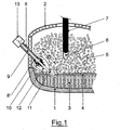
- the figure 1 schematically represents in vertical section a combined burner steel furnace comprising the device of the invention.
- FIGS.A to 2.F represent respective views in longitudinal and transverse section of several preferred embodiments of the invention.
- the figure 3 shows graphically an example of distance measurements over time obtained with the device according to the present invention, in the case of a combined burner.
- the main object of the invention is to provide dynamic control means combined burners (oxy-fuel / oxygen) and oxygen lances mounted on the walls of an arc furnace.
- these control means comprise an optical sensor, thus without contact, located outside the arc furnace, to estimate the distance between the end of the lance and a target constituted by solid gunmetal located opposite said end.
- the optical sensor is located inside the lance or behind it and consists of a measuring head comprising a source that emits a beam passing inside the lance towards the target, it is ie scrap not yet melted. The beam is reflected by the target towards a detector, located in the measuring head, also passing through the inside of the lance.
- the start time of the oxygen lance and the flow rate of oxygen insufflated will then be selected according to the actual scrap load in face of each individual lance, which is accurately estimated by means of the distance sensor.
- Any means other than optical means for example a radar system, ie a microwave or radio wave range finder, for determining distances in a noisy environment by a high temperature is likely to be also covered by the subject of the invention.
- a system for measuring the instantaneous distance between the end of the lance and the solid scrap must make it possible to adjust the points of operation of the lance, in order to avoid the disadvantages mentioned above and thus to increase the efficiency of oxygen supply.
- the calculation of dynamic operating points will also allow automatic operation of the burner and / or the lance.
- the oxygen / natural gas ratio, the burner output, the change from burner mode to oxygen blowing mode and the operating time of each burner will be calculated, if necessary, according to the actual scrap load in front of each burner. burner or lance.
- the lance When such a melting cavity has been formed, the lance will normally be driven under the nominal conditions.
- the distance sensor will be chosen to be able to target a target brought to a very high local temperature, without the measurement being too disturbed by the target's own radiation, at the wavelengths used. This sensor will also have to accommodate the presence of the flames generated in the case of a combined burner, which in particular can absorb the beam emitted and received by the sensor.
- FIG. 1 shows a fragmentary view of a steel arc furnace, in vertical section, in which a combi burner (burner + lance) comprising the device of the invention is schematically illustrated.
- the arc furnace comprises in particular a tank 1 closed by a lid 2, provided with water cooling means.
- the vessel 1 contains a bath of molten steel 3 covered, for the record, with a layer of slag 4.
- the steel in Melting 3 is poured through a taphole, well known to those skilled in the art (not shown).
- a new quantity of scrap 5 is loaded into the oven, lid 2 open, by means of a basket (not shown).
- the load of scrap 5 is melted progressively by means of an electric arc 6 formed between an electrode 7 and the molten steel bath 3, with the addition of burners such as the combined burner 8, well known in the state of the technique and developing flames 10 and / or a jet of oxygen under pressure 11 in a cavity 12.
- a detection head 13 of distance sensor type is integrated within the burner according to a preferred embodiment of the invention : this includes in particular a laser diode which generates a pulsed beam aimed at the scrap 5 through a central opening 9 of the burner and a photodetector disposed in a solid angle allowing it to detect the boring beam reflected on the scrap 5 .
- a free cavity is formed by melting in front of the end of the burner, as shown in FIG. figure 1 .
- This cavity defines a distance D between the end of the burner 8 'and the front scrap 5 still in the solid state. This distance D is precisely measured by the device of the invention.
- the radiation source 14 preferably laser, provided with its collimating optics 14A (lens), emits an incident beam (parallel) 16 through the viewing tube 9 'and the nozzle of the lance 9.
- the reflected beam 17 is sensed by the detector 15, via its collimating optics 15A.
- each beam can thus be delimited by a separate tube 18.
- a protective glass 19 against dust and projections of hot particles and an infrared filter 20 common to the two beams are advantageously provided in the sighting tube 9 ', in front of optics.
- the optical paths corresponding to incident beams 16 and reflected 17 are superimposed.
- the source 14 emits along an axis perpendicular to the axis of the lance and the detector 15 receives the beam reflected in said axis, by means of a beam splitter 21 (beamsplitter), for example a semi-transparent mirror, positioned at 45 ° with respect to said axis.
- a beam splitter 21 beamsplitter
- a diametrical wall 22 physically separates the two beams in the nozzle and two mirrors 23A, 23B, oriented at 45 ° with respect to the axis of the lance separate the two respective beams, the respective axes of the source 14 and the detector 15 being perpendicular to the axis of the lance.
- two respective deflection prisms 24A, 24B are used at the rear end of the sighting tube 9 '. These two deflection prisms allow the return or deflection of the beams incident and reflected on the two respective collimator lenses 14A, 15A of the optical system. More generally, it is possible to use “deflecting glasses”, that is to say transparent glasses that deflect light from a known angle. As for the previous device, it is possible to use a separating diametral partition 22.
- the incident beam may be of smaller section than the reflected beam, which favors the reception signal / noise ratio.
- the incident beam 16 is confined in a tube 18 of smaller section than the internal section of the nozzle.
- the reflected beam is returned at 90 ° to the axis of the lance, through a mirror 25.
- the tube 18 is closed at the rear and includes the emitter 14 and its collimating optics 14A, which is a lens or a group of lenses. In addition to promoting reception, this configuration keeps the detector 15 in the axis of the lance.
- the figure 3 illustrates graphically the measurement of distances D, according to the definition given above, as a function of time for a combi burner in operation, to from the start.
- zone A black dots
- the points corresponding to a measured distance are plotted as a function of the operating time.
- the burner will be stopped or not and we will go into oxygen blowing mode by actuation of the lance (zone B, dashed curve).
- zone B dashed curve
- This measurement therefore gives information allowing a better control of the installation. For example, if the distance measured remains low for a long time, this may be a sign of obstruction of the burner or lance. The control system will then stop the burner or lance and instruct the operator to initiate a cleaning or maintenance procedure for example.
- part of the oxygen blown by the lance may be devoted to cleaning these windows by scanning.
- the invention has the advantage that a dynamic and automatic control of the combined burners and lances makes it possible to ensure their optimal operation in a reliable and reproducible manner in order to obtain an improved or optimized scrap fusion by means of a consumption in electrical energy and reduced gas, thus making better use of the energy consumed.
Landscapes
- Engineering & Computer Science (AREA)
- Mechanical Engineering (AREA)
- General Engineering & Computer Science (AREA)
- Chemical & Material Sciences (AREA)
- Manufacturing & Machinery (AREA)
- Materials Engineering (AREA)
- Metallurgy (AREA)
- Organic Chemistry (AREA)
- Carbon Steel Or Casting Steel Manufacturing (AREA)
- Waste-Gas Treatment And Other Accessory Devices For Furnaces (AREA)
- Furnace Details (AREA)
- Vertical, Hearth, Or Arc Furnaces (AREA)
- Refinement Of Pig-Iron, Manufacture Of Cast Iron, And Steel Manufacture Other Than In Revolving Furnaces (AREA)
- Treatment Of Steel In Its Molten State (AREA)
- Meat, Egg Or Seafood Products (AREA)
- Pre-Mixing And Non-Premixing Gas Burner (AREA)
Claims (27)
- Gerät für die dynamische Steuerung in einem metallurgischen Ofen, einer Lanze (9) zum Einblasen von unter Druck stehendem Gas, das Sauerstoff oder Feststoffe oder gasförmigen oder flüssigen Brennstoff enthält, oberhalb eines Bades mit geschmolzenem Metall (3); über dem besagten Metallschmelzbad ist eine Ladung Metallschrott angebracht, wobei das besagte Gerät Hilfsmittel zur berührungslosen Messung enthält, die sich an der Ofenaußenseite befinden, um den Abstand (D) zwischen dem einem Ende (8') der Lanze (9) und einem Ziel (5), das durch den festen Metallschrott, der sich gegenüber dem besagten Ende (8') befindet, einzuschätzen, wobei die besagten Hilfsmittel zur berührungslosen Messung eine Strahlungsquelle (14), die einen ursprünglichen Strahl (16) in Richtung des besagten Ziels (5) sowie einen Sensor (15), in dem ein durch das Ziel (5) reflektierter Strahl (17) erfasst wird, abgibt, umfassen, so dass der ursprüngliche Strahl (16) und der reflektierte Strahl (17) beide durch den Innenquerschnitt einer Düse, die sich in der Achse mit der besagten Lanze (9) befindet, geführt werden, wobei das besagte Gerät sich dadurch auszeichnet, dass es Hilfsmittel zur Reduzierung des Durchmessers des ursprünglichen (16) und reflektierten (17) Strahles in der Düse auf einen Wert von weniger als 30 mm einschließt.
- Gerät entsprechend dem Anspruch 1, dadurch gekennzeichnet, dass die besagten Hilfsmittel es gestatten, den Durchmesser des ursprünglichen (16) und des reflektierten Strahls (17) in der Düse auf einen Wert von weniger als 20 mm zu reduzieren.
- Gerät entsprechend dem Anspruch 1, dadurch gekennzeichnet, dass der ursprüngliche Strahl (16) und der reflektierte Strahl (17) mit der Achse der Lanze parallel verlaufen und durch ein Rohr (18) mit einem Durchmesser, der geringer als der Innendurchmesser der Düse ist, begrenzt werden.
- Gerät entsprechend dem Anspruch 1, dadurch gekennzeichnet, dass der ursprüngliche Strahl (16) und der reflektierte Strahl (17) sich zumindest teilweise im Inneren der Düse überlagern.
- Gerät entsprechend dem Anspruch 4, dadurch gekennzeichnet, dass es einen Strahlenteiler (21) beinhaltet, der im Vergleich zur Achse der Lanze um 45° geneigt ist; hierbei gibt die Lichtquelle (14) auf den besagten Strahlenteiler entsprechend einer Achse im rechten Winkel einen Strahl ab, während der Sensor (15), den reflektierten Strahl (17) entsprechend der besagten Achse empfängt.
- Gerät entsprechend dem Anspruch 1, dadurch gekennzeichnet, dass der ursprünglich abgegebene Strahl (16) und der reflektierte Strahl (17) in der Düse durch eine diametrale Trennwand (22) begrenzt werden; hierbei gibt die Quelle (14) den ursprünglichen Strahl (16) entsprechend einer rechtwinklig zur Achse der Lanze stehenden Achse auf einen ersten Spiegel (23A) ab, der im Vergleich zur besagten Achse um 45° geneigt ist und der Empfänger (15) empfängt den reflektierten Strahl (17) entsprechend einer senkrecht zur Lanzenachse stehenden Achse über einen zweiten Spiegel (23B), der im Vergleich zur besagten Achse um 45° geneigt ist.
- Gerät entsprechend dem Anspruch 1, dadurch gekennzeichnet, dass der ursprüngliche Strahl (16) und der reflektierte Strahl (17) in der Düse durch eine diametrale Abtrennung (22) begrenzt werden; die Quelle (14) gibt den ursprünglichen Strahl (16) ab und der Empfänger (15) empfängt den reflektierten Strahl (17) entsprechend der, im Vergleich zur Achse der Lanze, dank zweier ablenkenden Prismen (24A, 24B), jeweils schräg angeordneten Achsen.
- Gerät entsprechend dem Anspruch 1, dadurch gekennzeichnet, dass die Quelle (14) den ursprünglichen Strahl (16) in der Achse der Lanze abgibt; letztere ist hierbei in einem Rohr (18) mit einem geringeren Querschnitt als der Düse eingeschlossen, während der reflektierte Strahl (17) an der Außenseite des besagten Rohres (18) durch die Düse geführt wird.
- Gerät entsprechend dem Anspruch 8, dadurch gekennzeichnet, dass der reflektierte Strahl (17) durch einen Spiegel (25) auf den Sensor (15) außerhalb der Achse der Lanze abgelenkt wird.
- Gerät entsprechend dem Anspruch 8, dadurch gekennzeichnet, dass die Quelle (14) im Rohr (18), das an der Rückseite verschlossen ist, eingekapselt ist; hierbei wird der reflektierte Strahl (17) vom Sensor (15) in der Achse der Lanze empfangen.
- Gerät entsprechend dem Anspruch 1, dadurch gekennzeichnet, dass die Hilfsmittel zur Abstandsmessung (D) zwischen dem einem Ende (8') der Lanze (9) und dem festen Metallschrott (5) einen Messfühler (13) vom Typ optischer Entfernungssensor enthalten, der sich im Inneren oder hinter der Lanze (9) befindet und der mit einem vorzugsweise gepulsten Laser (14) ausgestattet ist, der den ursprünglichen Strahl(16) abgibt, der auf den Metallschrott (5) quer durch die Düse , die sich in der Achse der Lanze (9) befindet, abzielt; ferner beinhalten die Hilfsmittel zur Abstandsmessung einen Photodetektor (15), der in der Lage ist, quer durch diese gleiche Düse den durch den Metallschrott (5) reflektierten Laserstrahl(17) zu empfangen.
- Gerät entsprechend dem Anspruch 11, dadurch gekennzeichnet, dass der Messfühler (13) so konfiguriert ist, dass er die Entfernungsmessung an einem auf eine hohe Temperatur, vorzugsweise auf eine Temperatur von bis zu 1500°C, gebrachten Ziel, durchführen kann und/oder dass er die besagte Messung in einer Umgebung oder auf einer optischen Strecke, auf der Flammen vorhanden sind, durchführen kann.
- Gerät entsprechend irgendeinem der Ansprüche 11 bis 12, dadurch gekennzeichnet, dass der Messfühler (13) mit Kühlvorrichtungen ausgestattet ist.
- Gerät entsprechend irgendeinem der Ansprüche 11 bis 13, dadurch gekennzeichnet, dass es sich bei dem Laser (14) um eine Halbleiter-Laserdiode handelt, die Strahlen im Infrarotbereich aussendet und mindestens mit einer Kollimatorlinse und einem Filter, vorzugsweise mit einem Interferenzfilter, ausgestattet ist, um den Störuntergrund der Eigenstrahlung des Ofens zu beseitigen oder zu dämpfen.
- Gerät entsprechend irgendeinem der Ansprüche 11 bis 14, dadurch gekennzeichnet, dass der Photodetektor (15) mindestens eine Empfangslinse mit einem Interferenzfilter und mindestens eine Photodiode, die mit einem elektronischen Hochfrequenz-Erkennungssystem gekoppelt ist, enthält.
- Gerät entsprechend dem Anspruch 15, dadurch gekennzeichnet, dass die Photodiode über eine Faseroptik mit dem elektronischen Hochfrequenz-Erkennungssystem gekoppelt ist.
- Gerät entsprechend irgendeinem der Ansprüche 11 bis 16, dadurch gekennzeichnet, dass der Messfühler (13) ein Schutzfenster (19) beinhaltet.
- Gerät entsprechend dem Anspruch 17, dadurch gekennzeichnet, dass das Schutzfenster (19) mit einer Schutzvorrichtung durch Überstreichen mit unter Druck stehendem Sauerstoff, der auf der Höhe der besagten Lanze (9) abgenommen wurde, sowie mit einem für den Sender (14) und den Detektor (15) gemeinsamen Filter, der die Infrarot-Störstrahlung beseitigt oder dämpft, ausgestattet ist.
- Gerät entsprechend irgendeinem der Ansprüche 11 bis 18, dadurch gekennzeichnet, dass der Messfühler (13) so konfiguriert wurde, dass er Abstände bis zu 5 m messen kann.
- Gerät entsprechend irgendeinem der Ansprüche 1 bis 19, dadurch gekennzeichnet, dass die Lanze (9) für das Einblasen von Gas unter Druck, die Sauerstoff oder Feststoffe oder gasförmige oder flüssige Brennstoffe enthält, mit einem Brenner (8) mit gasförmigem oder flüssigem Brennstoff kombiniert ist; der besagte Brenner(8) gibt bei Nutzung eine Flamme (10) durch eine Öffnung, die sich am besagten Ende (8') der Lanze befindet (9), ab.
- Gerät entsprechend irgendeinem der Ansprüche 11 bis 19, dadurch gekennzeichnet, dass es zudem Hilfsmittel für die Regelung zur Einstellung in Echtzeit der Durchflussmenge oder des Sauerstoffdrucks der Lanze (9), des Einsatzmoments der Sauerstoffeinblasung durch die Lanze (9) beinhaltet.
- Gerät entsprechend dem Anspruch 20, dadurch gekennzeichnet, dass es zudem Regeleinrichtungen zur Einstellung in Echtzeit des Verhältnisses des oxidierenden Gases/Brennmaterials auf der Ebene der Brennerversorgung (8) und/oder der Brennerleistung und/oder der Funktionsdauer des Brenners, in Abhängigkeit des durch den Messfühler (13) und die Hochfrequenzelektronik gemessenen Abstands (D) beinhaltet.
- Gerät entsprechend dem Anspruch 21 oder 22, dadurch gekennzeichnet, dass es sich bei den besagten Regeleinrichtungen um Regeleinrichtungen in einem geschlossenen Kreislauf handelt.
- Gerät entsprechend dem Anspruch 20, dadurch gekennzeichnet, dass die Lanze (9) und der Brenner (8) kombiniert und konzentrisch sind.
- Gerät entsprechend dem Anspruch 20, dadurch gekennzeichnet, dass die Lanze (9) und der Brenner (8) im Ofen physikalisch getrennt sind.
- Lanze für das Einblasen von Sauerstoff (9) für einen elektrischen Lichtbogenofen, der mit einer dynamischen Steuerungsvorrichtung entsprechend irdendeinem der Ansprüche 1 bis 19 ausgestattet ist.
- Lanze für das Einblasen von Sauerstoff (9), kombiniert mit einem Sauerstoff-Brennstoff-Brenner (8) für einen elektrischen Lichtbogenofen, der mit einer Vorrichtung zur dynamischen Steuerung entsprechend dem Anspruch 20 ausgestattet ist.
Applications Claiming Priority (2)
| Application Number | Priority Date | Filing Date | Title |
|---|---|---|---|
| BE2006/0246A BE1017112A3 (fr) | 2006-04-26 | 2006-04-26 | Dispositif et procede de controle dynamique des bruleurs combines et des lances d'insufflation d'oxygene dans un four. |
| PCT/BE2007/000034 WO2007121539A2 (fr) | 2006-04-26 | 2007-04-23 | Dispositif et procede de controle dynamique des bruleurs combines et des lances d'insufflation d'oxygene dans un four |
Publications (2)
| Publication Number | Publication Date |
|---|---|
| EP2010682A2 EP2010682A2 (de) | 2009-01-07 |
| EP2010682B1 true EP2010682B1 (de) | 2010-08-04 |
Family
ID=37667290
Family Applications (1)
| Application Number | Title | Priority Date | Filing Date |
|---|---|---|---|
| EP20070719198 Not-in-force EP2010682B1 (de) | 2006-04-26 | 2007-04-23 | Vorrichtung und verfahren zur dynamischen steuerung von kombinierten brennern und lanzen zum einblasen von sauerstoff in einen ofen |
Country Status (7)
| Country | Link |
|---|---|
| EP (1) | EP2010682B1 (de) |
| JP (1) | JP5330226B2 (de) |
| KR (1) | KR101348258B1 (de) |
| AT (1) | ATE476532T1 (de) |
| BE (1) | BE1017112A3 (de) |
| DE (1) | DE602007008223D1 (de) |
| WO (1) | WO2007121539A2 (de) |
Cited By (1)
| Publication number | Priority date | Publication date | Assignee | Title |
|---|---|---|---|---|
| EP4269923A4 (de) * | 2021-02-10 | 2024-07-31 | JFE Steel Corporation | Mit videovorrichtung ausgestatteter elektroofen |
Families Citing this family (5)
| Publication number | Priority date | Publication date | Assignee | Title |
|---|---|---|---|---|
| JP2015067875A (ja) * | 2013-09-30 | 2015-04-13 | スチールプランテック株式会社 | ランス設備、およびそれを用いた精錬炉、ならびにランス位置調節方法 |
| US10504758B2 (en) * | 2014-02-14 | 2019-12-10 | Taiwan Semiconductor Manufacturing Company Ltd. | Nozzle having real time inspection functions |
| KR102061953B1 (ko) * | 2015-01-27 | 2020-01-02 | 제이에프이 스틸 가부시키가이샤 | 전기로에 의한 용철의 제조 방법 |
| KR102098019B1 (ko) * | 2017-12-26 | 2020-04-07 | 주식회사 포스코 | 전기로의 버너 연소 제어 장치 및 방법 |
| CN112815702B (zh) * | 2020-12-12 | 2023-08-22 | 舞阳钢铁有限责任公司 | 减少Cr-Mo钢坯料连续炉内烧损的生产方法 |
Family Cites Families (7)
| Publication number | Priority date | Publication date | Assignee | Title |
|---|---|---|---|---|
| BE756177A (fr) * | 1969-09-17 | 1971-03-15 | Shell Int Research | Procede de preparation de copolymeres a blocs hydrogenes |
| US4106756A (en) * | 1976-11-01 | 1978-08-15 | Pullman Berry Company | Oxygen lance and sensing adapter arrangement |
| DE2745251C2 (de) * | 1977-10-07 | 1986-07-10 | Siemens AG, 1000 Berlin und 8000 München | Einrichtung zur berührungsfreien Messung der Standhöhe der Schmelze in einem metallurgischen Schmelzgefäß |
| JPH02254345A (ja) * | 1989-03-29 | 1990-10-15 | Sumitomo Metal Ind Ltd | 溶融金属のレーザー発光分光分析方法及び装置 |
| US5557631A (en) * | 1994-05-06 | 1996-09-17 | Dynex Engineering Inc. | Sonic furnace monitoring apparatus |
| US6596995B1 (en) * | 2002-03-07 | 2003-07-22 | Manfred Bender | Remote sensing of molten metal properties |
| BE1016551A3 (fr) * | 2005-03-16 | 2007-01-09 | Ct Rech Metallurgiques Asbl | Dispositif et procede de controle dynamique de la combustion d'un bruleur dans un four electrique a arc. |
-
2006
- 2006-04-26 BE BE2006/0246A patent/BE1017112A3/fr not_active IP Right Cessation
-
2007
- 2007-04-23 WO PCT/BE2007/000034 patent/WO2007121539A2/fr not_active Ceased
- 2007-04-23 DE DE200760008223 patent/DE602007008223D1/de active Active
- 2007-04-23 AT AT07719198T patent/ATE476532T1/de not_active IP Right Cessation
- 2007-04-23 JP JP2009506869A patent/JP5330226B2/ja not_active Expired - Fee Related
- 2007-04-23 KR KR1020087028665A patent/KR101348258B1/ko not_active Expired - Fee Related
- 2007-04-23 EP EP20070719198 patent/EP2010682B1/de not_active Not-in-force
Cited By (1)
| Publication number | Priority date | Publication date | Assignee | Title |
|---|---|---|---|---|
| EP4269923A4 (de) * | 2021-02-10 | 2024-07-31 | JFE Steel Corporation | Mit videovorrichtung ausgestatteter elektroofen |
Also Published As
| Publication number | Publication date |
|---|---|
| DE602007008223D1 (de) | 2010-09-16 |
| KR101348258B1 (ko) | 2014-01-15 |
| BE1017112A3 (fr) | 2008-02-05 |
| WO2007121539A2 (fr) | 2007-11-01 |
| WO2007121539A3 (fr) | 2008-04-17 |
| JP5330226B2 (ja) | 2013-10-30 |
| EP2010682A2 (de) | 2009-01-07 |
| ATE476532T1 (de) | 2010-08-15 |
| KR20080113295A (ko) | 2008-12-29 |
| JP2009534627A (ja) | 2009-09-24 |
Similar Documents
| Publication | Publication Date | Title |
|---|---|---|
| EP2010682B1 (de) | Vorrichtung und verfahren zur dynamischen steuerung von kombinierten brennern und lanzen zum einblasen von sauerstoff in einen ofen | |
| CN102472667B (zh) | 无接触地检测金属熔液的温度t的方法和装置 | |
| US20140327192A1 (en) | Method for operating an oxygen blowing lance in a metallurgical vessel and a measurement system for determining a measurement signal used in the method | |
| JP5551086B2 (ja) | 電気アーク炉用のバーナー及びランス複合装置 | |
| WO2008003908A2 (fr) | Brûleur à flamme à direction et/ou ouverture variable et procédé de mise en oeuvre | |
| EP0216694B1 (de) | Vorrichtung zur Echtzeitkontrolle von Schweissungen, insbesondere für nicht direkt beobachtbare Schweissstellen | |
| JP4734273B2 (ja) | レーザ誘起蛍光分析装置 | |
| FR2765129A1 (fr) | Procede de soudage de toles revetues par un faisceau d'energie, tel qu'un faisceau laser | |
| EP2041493B1 (de) | Verfahren zur erhitzung einer ladung | |
| EP2479524B1 (de) | Schlackeüberwachungsvorrichtung für einen kohlevergaser und kohlevergaser | |
| EP1703241B1 (de) | Vorrichtung und Verfahren zur dynamischen Steuerung eines Brenners in einem Lichtbogenofen | |
| WO1999003636A1 (fr) | Dispositif et procede de decoupe a distance etendue par laser, en mode impulsionnel | |
| FR2903325A1 (fr) | Procede et appareil d'injection d'un jet de fluide de direction et/ou d'ouverture variable | |
| KR20070103076A (ko) | 용융 금속 배스의 광학 분석 시스템 | |
| EP3715717B9 (de) | Verbrennungsverfahren und brenner für dessen umsetzung | |
| WO2010127713A1 (fr) | Méthode et dispositif d'analyse spectrale d'une couche de revêtement métallique déposé à la surface d'une bande d'acier | |
| FR2710740A1 (fr) | Procédé de mesure de l'évolution de la longueur d'une tuyère pour l'introduction d'un fluide dans un métal liquide contenu dans un récipient métallurgique, et dispositif pour sa mise en Óoeuvre. | |
| WO2019011935A1 (en) | ENHANCEMENT DEPOSITION ARRANGEMENT AND OPTIMAL CLEANING OF WATER SCREEN TUBES IN THE FURNACE OF BIOMASS COMBUSTION BOILERS | |
| MXPA05002181A (es) | Dispositivo y procedimiento de control de una operacion de soldadura, de recargue o de mecanizado por haz laser de una pieza. | |
| JP5052962B2 (ja) | 精錬モニタリング装置及び方法 | |
| FR2825777A1 (fr) | Dispositif et procede de combustion par lance a recirculation | |
| JP2005024446A (ja) | 精錬炉内溶融金属モニタリング方法及び装置 | |
| FR2822940A1 (fr) | Procede, lance et tuyere d'injection d'oxygene radialement dans un four | |
| EP0043329A1 (de) | Elektrischer Lichtbogenofen mit gesteuertem Betrieb | |
| WO2008077900A1 (en) | Device and method for measuring the temperature of the liquid metal in an electric furnace |
Legal Events
| Date | Code | Title | Description |
|---|---|---|---|
| PUAI | Public reference made under article 153(3) epc to a published international application that has entered the european phase |
Free format text: ORIGINAL CODE: 0009012 |
|
| 17P | Request for examination filed |
Effective date: 20081022 |
|
| AK | Designated contracting states |
Kind code of ref document: A2 Designated state(s): AT BE BG CH CY CZ DE DK EE ES FI FR GB GR HU IE IS IT LI LT LU LV MC MT NL PL PT RO SE SI SK TR |
|
| AX | Request for extension of the european patent |
Extension state: AL BA HR MK RS |
|
| GRAP | Despatch of communication of intention to grant a patent |
Free format text: ORIGINAL CODE: EPIDOSNIGR1 |
|
| DAX | Request for extension of the european patent (deleted) | ||
| GRAS | Grant fee paid |
Free format text: ORIGINAL CODE: EPIDOSNIGR3 |
|
| GRAA | (expected) grant |
Free format text: ORIGINAL CODE: 0009210 |
|
| RAP3 | Party data changed (applicant data changed or rights of an application transferred) |
Owner name: CENTRE DE RECHERCHES METALLURGIQUES ASBL - CENTRUM |
|
| AK | Designated contracting states |
Kind code of ref document: B1 Designated state(s): AT BE BG CH CY CZ DE DK EE ES FI FR GB GR HU IE IS IT LI LT LU LV MC MT NL PL PT RO SE SI SK TR |
|
| REG | Reference to a national code |
Ref country code: GB Ref legal event code: FG4D Free format text: NOT ENGLISH |
|
| REG | Reference to a national code |
Ref country code: CH Ref legal event code: EP |
|
| REG | Reference to a national code |
Ref country code: IE Ref legal event code: FG4D Free format text: LANGUAGE OF EP DOCUMENT: FRENCH |
|
| REF | Corresponds to: |
Ref document number: 602007008223 Country of ref document: DE Date of ref document: 20100916 Kind code of ref document: P |
|
| REG | Reference to a national code |
Ref country code: NL Ref legal event code: VDEP Effective date: 20100804 |
|
| LTIE | Lt: invalidation of european patent or patent extension |
Effective date: 20100804 |
|
| PG25 | Lapsed in a contracting state [announced via postgrant information from national office to epo] |
Ref country code: NL Free format text: LAPSE BECAUSE OF FAILURE TO SUBMIT A TRANSLATION OF THE DESCRIPTION OR TO PAY THE FEE WITHIN THE PRESCRIBED TIME-LIMIT Effective date: 20100804 Ref country code: LT Free format text: LAPSE BECAUSE OF FAILURE TO SUBMIT A TRANSLATION OF THE DESCRIPTION OR TO PAY THE FEE WITHIN THE PRESCRIBED TIME-LIMIT Effective date: 20100804 Ref country code: AT Free format text: LAPSE BECAUSE OF FAILURE TO SUBMIT A TRANSLATION OF THE DESCRIPTION OR TO PAY THE FEE WITHIN THE PRESCRIBED TIME-LIMIT Effective date: 20100804 Ref country code: FI Free format text: LAPSE BECAUSE OF FAILURE TO SUBMIT A TRANSLATION OF THE DESCRIPTION OR TO PAY THE FEE WITHIN THE PRESCRIBED TIME-LIMIT Effective date: 20100804 |
|
| PG25 | Lapsed in a contracting state [announced via postgrant information from national office to epo] |
Ref country code: SI Free format text: LAPSE BECAUSE OF FAILURE TO SUBMIT A TRANSLATION OF THE DESCRIPTION OR TO PAY THE FEE WITHIN THE PRESCRIBED TIME-LIMIT Effective date: 20100804 Ref country code: PT Free format text: LAPSE BECAUSE OF FAILURE TO SUBMIT A TRANSLATION OF THE DESCRIPTION OR TO PAY THE FEE WITHIN THE PRESCRIBED TIME-LIMIT Effective date: 20101206 Ref country code: PL Free format text: LAPSE BECAUSE OF FAILURE TO SUBMIT A TRANSLATION OF THE DESCRIPTION OR TO PAY THE FEE WITHIN THE PRESCRIBED TIME-LIMIT Effective date: 20100804 Ref country code: IS Free format text: LAPSE BECAUSE OF FAILURE TO SUBMIT A TRANSLATION OF THE DESCRIPTION OR TO PAY THE FEE WITHIN THE PRESCRIBED TIME-LIMIT Effective date: 20101204 Ref country code: CY Free format text: LAPSE BECAUSE OF FAILURE TO SUBMIT A TRANSLATION OF THE DESCRIPTION OR TO PAY THE FEE WITHIN THE PRESCRIBED TIME-LIMIT Effective date: 20100804 Ref country code: BG Free format text: LAPSE BECAUSE OF FAILURE TO SUBMIT A TRANSLATION OF THE DESCRIPTION OR TO PAY THE FEE WITHIN THE PRESCRIBED TIME-LIMIT Effective date: 20101104 |
|
| REG | Reference to a national code |
Ref country code: IE Ref legal event code: FD4D |
|
| PG25 | Lapsed in a contracting state [announced via postgrant information from national office to epo] |
Ref country code: GR Free format text: LAPSE BECAUSE OF FAILURE TO SUBMIT A TRANSLATION OF THE DESCRIPTION OR TO PAY THE FEE WITHIN THE PRESCRIBED TIME-LIMIT Effective date: 20101105 Ref country code: LV Free format text: LAPSE BECAUSE OF FAILURE TO SUBMIT A TRANSLATION OF THE DESCRIPTION OR TO PAY THE FEE WITHIN THE PRESCRIBED TIME-LIMIT Effective date: 20100804 Ref country code: SE Free format text: LAPSE BECAUSE OF FAILURE TO SUBMIT A TRANSLATION OF THE DESCRIPTION OR TO PAY THE FEE WITHIN THE PRESCRIBED TIME-LIMIT Effective date: 20100804 |
|
| PG25 | Lapsed in a contracting state [announced via postgrant information from national office to epo] |
Ref country code: IE Free format text: LAPSE BECAUSE OF FAILURE TO SUBMIT A TRANSLATION OF THE DESCRIPTION OR TO PAY THE FEE WITHIN THE PRESCRIBED TIME-LIMIT Effective date: 20100804 Ref country code: DK Free format text: LAPSE BECAUSE OF FAILURE TO SUBMIT A TRANSLATION OF THE DESCRIPTION OR TO PAY THE FEE WITHIN THE PRESCRIBED TIME-LIMIT Effective date: 20100804 |
|
| PLBI | Opposition filed |
Free format text: ORIGINAL CODE: 0009260 |
|
| PG25 | Lapsed in a contracting state [announced via postgrant information from national office to epo] |
Ref country code: SK Free format text: LAPSE BECAUSE OF FAILURE TO SUBMIT A TRANSLATION OF THE DESCRIPTION OR TO PAY THE FEE WITHIN THE PRESCRIBED TIME-LIMIT Effective date: 20100804 Ref country code: CZ Free format text: LAPSE BECAUSE OF FAILURE TO SUBMIT A TRANSLATION OF THE DESCRIPTION OR TO PAY THE FEE WITHIN THE PRESCRIBED TIME-LIMIT Effective date: 20100804 Ref country code: RO Free format text: LAPSE BECAUSE OF FAILURE TO SUBMIT A TRANSLATION OF THE DESCRIPTION OR TO PAY THE FEE WITHIN THE PRESCRIBED TIME-LIMIT Effective date: 20100804 Ref country code: EE Free format text: LAPSE BECAUSE OF FAILURE TO SUBMIT A TRANSLATION OF THE DESCRIPTION OR TO PAY THE FEE WITHIN THE PRESCRIBED TIME-LIMIT Effective date: 20100804 Ref country code: IT Free format text: LAPSE BECAUSE OF FAILURE TO SUBMIT A TRANSLATION OF THE DESCRIPTION OR TO PAY THE FEE WITHIN THE PRESCRIBED TIME-LIMIT Effective date: 20100804 |
|
| 26 | Opposition filed |
Opponent name: SIEMENS AKTIENGESELLSCHAFT Effective date: 20110504 |
|
| PLAX | Notice of opposition and request to file observation + time limit sent |
Free format text: ORIGINAL CODE: EPIDOSNOBS2 |
|
| PG25 | Lapsed in a contracting state [announced via postgrant information from national office to epo] |
Ref country code: ES Free format text: LAPSE BECAUSE OF FAILURE TO SUBMIT A TRANSLATION OF THE DESCRIPTION OR TO PAY THE FEE WITHIN THE PRESCRIBED TIME-LIMIT Effective date: 20101115 |
|
| REG | Reference to a national code |
Ref country code: DE Ref legal event code: R026 Ref document number: 602007008223 Country of ref document: DE Effective date: 20110504 |
|
| PLAF | Information modified related to communication of a notice of opposition and request to file observations + time limit |
Free format text: ORIGINAL CODE: EPIDOSCOBS2 |
|
| PG25 | Lapsed in a contracting state [announced via postgrant information from national office to epo] |
Ref country code: MC Free format text: LAPSE BECAUSE OF NON-PAYMENT OF DUE FEES Effective date: 20110430 |
|
| REG | Reference to a national code |
Ref country code: CH Ref legal event code: PL |
|
| GBPC | Gb: european patent ceased through non-payment of renewal fee |
Effective date: 20110423 |
|
| PLBB | Reply of patent proprietor to notice(s) of opposition received |
Free format text: ORIGINAL CODE: EPIDOSNOBS3 |
|
| PG25 | Lapsed in a contracting state [announced via postgrant information from national office to epo] |
Ref country code: MT Free format text: LAPSE BECAUSE OF FAILURE TO SUBMIT A TRANSLATION OF THE DESCRIPTION OR TO PAY THE FEE WITHIN THE PRESCRIBED TIME-LIMIT Effective date: 20100804 |
|
| REG | Reference to a national code |
Ref country code: FR Ref legal event code: ST Effective date: 20111230 |
|
| PG25 | Lapsed in a contracting state [announced via postgrant information from national office to epo] |
Ref country code: CH Free format text: LAPSE BECAUSE OF NON-PAYMENT OF DUE FEES Effective date: 20110430 Ref country code: FR Free format text: LAPSE BECAUSE OF NON-PAYMENT OF DUE FEES Effective date: 20110502 Ref country code: LI Free format text: LAPSE BECAUSE OF NON-PAYMENT OF DUE FEES Effective date: 20110430 |
|
| PG25 | Lapsed in a contracting state [announced via postgrant information from national office to epo] |
Ref country code: GB Free format text: LAPSE BECAUSE OF NON-PAYMENT OF DUE FEES Effective date: 20110423 |
|
| PG25 | Lapsed in a contracting state [announced via postgrant information from national office to epo] |
Ref country code: LU Free format text: LAPSE BECAUSE OF NON-PAYMENT OF DUE FEES Effective date: 20110423 |
|
| PG25 | Lapsed in a contracting state [announced via postgrant information from national office to epo] |
Ref country code: TR Free format text: LAPSE BECAUSE OF FAILURE TO SUBMIT A TRANSLATION OF THE DESCRIPTION OR TO PAY THE FEE WITHIN THE PRESCRIBED TIME-LIMIT Effective date: 20100804 |
|
| PG25 | Lapsed in a contracting state [announced via postgrant information from national office to epo] |
Ref country code: HU Free format text: LAPSE BECAUSE OF FAILURE TO SUBMIT A TRANSLATION OF THE DESCRIPTION OR TO PAY THE FEE WITHIN THE PRESCRIBED TIME-LIMIT Effective date: 20100804 |
|
| PLCK | Communication despatched that opposition was rejected |
Free format text: ORIGINAL CODE: EPIDOSNREJ1 |
|
| RAP2 | Party data changed (patent owner data changed or rights of a patent transferred) |
Owner name: CENTRE DE RECHERCHES METALLURGIQUES ASBL - CENTRUM |
|
| APAH | Appeal reference modified |
Free format text: ORIGINAL CODE: EPIDOSCREFNO |
|
| APBM | Appeal reference recorded |
Free format text: ORIGINAL CODE: EPIDOSNREFNO |
|
| APBP | Date of receipt of notice of appeal recorded |
Free format text: ORIGINAL CODE: EPIDOSNNOA2O |
|
| APBQ | Date of receipt of statement of grounds of appeal recorded |
Free format text: ORIGINAL CODE: EPIDOSNNOA3O |
|
| RAP2 | Party data changed (patent owner data changed or rights of a patent transferred) |
Owner name: CENTRE DE RECHERCHES METALLURGIQUES ASBL - CENTRUM |
|
| REG | Reference to a national code |
Ref country code: DE Ref legal event code: R100 Ref document number: 602007008223 Country of ref document: DE |
|
| APBU | Appeal procedure closed |
Free format text: ORIGINAL CODE: EPIDOSNNOA9O |
|
| PLAB | Opposition data, opponent's data or that of the opponent's representative modified |
Free format text: ORIGINAL CODE: 0009299OPPO |
|
| R26 | Opposition filed (corrected) |
Opponent name: SIEMENS AKTIENGESELLSCHAFT Effective date: 20110504 |
|
| PLBN | Opposition rejected |
Free format text: ORIGINAL CODE: 0009273 |
|
| STAA | Information on the status of an ep patent application or granted ep patent |
Free format text: STATUS: OPPOSITION REJECTED |
|
| 27O | Opposition rejected |
Effective date: 20151113 |
|
| PGFP | Annual fee paid to national office [announced via postgrant information from national office to epo] |
Ref country code: BE Payment date: 20230330 Year of fee payment: 17 |
|
| P01 | Opt-out of the competence of the unified patent court (upc) registered |
Effective date: 20230413 |
|
| PGFP | Annual fee paid to national office [announced via postgrant information from national office to epo] |
Ref country code: DE Payment date: 20230412 Year of fee payment: 17 |
|
| REG | Reference to a national code |
Ref country code: DE Ref legal event code: R119 Ref document number: 602007008223 Country of ref document: DE |
|
| REG | Reference to a national code |
Ref country code: BE Ref legal event code: MM Effective date: 20240430 |
|
| PG25 | Lapsed in a contracting state [announced via postgrant information from national office to epo] |
Ref country code: DE Free format text: LAPSE BECAUSE OF NON-PAYMENT OF DUE FEES Effective date: 20241105 |
|
| PG25 | Lapsed in a contracting state [announced via postgrant information from national office to epo] |
Ref country code: BE Free format text: LAPSE BECAUSE OF NON-PAYMENT OF DUE FEES Effective date: 20240430 |
|
| PG25 | Lapsed in a contracting state [announced via postgrant information from national office to epo] |
Ref country code: DE Free format text: LAPSE BECAUSE OF NON-PAYMENT OF DUE FEES Effective date: 20241105 Ref country code: BE Free format text: LAPSE BECAUSE OF NON-PAYMENT OF DUE FEES Effective date: 20240430 |