EP2010002B1 - Vorrichtung zum ausgeben von speiseeis - Google Patents
Vorrichtung zum ausgeben von speiseeis Download PDFInfo
- Publication number
- EP2010002B1 EP2010002B1 EP07724472A EP07724472A EP2010002B1 EP 2010002 B1 EP2010002 B1 EP 2010002B1 EP 07724472 A EP07724472 A EP 07724472A EP 07724472 A EP07724472 A EP 07724472A EP 2010002 B1 EP2010002 B1 EP 2010002B1
- Authority
- EP
- European Patent Office
- Prior art keywords
- receiving part
- housing
- pressure
- assembly
- region
- Prior art date
- Legal status (The legal status is an assumption and is not a legal conclusion. Google has not performed a legal analysis and makes no representation as to the accuracy of the status listed.)
- Not-in-force
Links
Images


Classifications
-
- A—HUMAN NECESSITIES
- A23—FOODS OR FOODSTUFFS; TREATMENT THEREOF, NOT COVERED BY OTHER CLASSES
- A23G—COCOA; COCOA PRODUCTS, e.g. CHOCOLATE; SUBSTITUTES FOR COCOA OR COCOA PRODUCTS; CONFECTIONERY; CHEWING GUM; ICE-CREAM; PREPARATION THEREOF
- A23G9/00—Frozen sweets, e.g. ice confectionery, ice-cream; Mixtures therefor
- A23G9/04—Production of frozen sweets, e.g. ice-cream
- A23G9/22—Details, component parts or accessories of apparatus insofar as not peculiar to a single one of the preceding groups
- A23G9/28—Details, component parts or accessories of apparatus insofar as not peculiar to a single one of the preceding groups for portioning or dispensing
- A23G9/281—Details, component parts or accessories of apparatus insofar as not peculiar to a single one of the preceding groups for portioning or dispensing at the discharge end of freezing chambers
- A23G9/285—Details, component parts or accessories of apparatus insofar as not peculiar to a single one of the preceding groups for portioning or dispensing at the discharge end of freezing chambers for extruding strips, cutting blocks and manipulating cut blocks
Definitions
- the invention relates to a device for dispensing ice cream, in particular in the form of spaghetti ice, according to the preamble of claim 1.
- a cup-shaped reservoir is filled with an ice cream portion and squeezed through bottom openings of the reservoir, so that the ice is shaped like spaghetti noodles.
- This device has a tubular stand on which on the one hand the reservoir and on the other hand a hand lever are held, by means of which a pressure piece in the reservoir can be pivoted.
- DE 22 14 023 and DE 26 25 906 are machines for processing ice cream o.
- Foods known, with a piston press and effective as a nozzle tool reservoir are provided and from this the ice cream, the dough o. The like, is pressed out largely automatically.
- DE 28 13 349 shows a generic ice cream machine in which a plunger of a reciprocating press is provided with a drive shaft which is coupled by means of an open inside the housing interior threaded connection directly to a drive motor, so that an axial displacement of the plunger is possible.
- This large construction in coaxial design is by a variety of items less easy to assemble or disassembly, has high wear and requires a lot of time in cleaning.
- the housing are in the interior leading gap areas by exposed contact elements, snaps u.
- Components required so that there is a high risk of contamination and thus there is a failure-prone and strict hygiene requirements not appropriate design.
- the invention is concerned with the problem of providing a device for dispensing spaghetti ice, whose reduced noise pollution leading Preßkolbenantrieb can be integrated into a producible with little technical effort and compact housing part and the overall concept of the device with low space requirements a largely self-sufficient use at different places of application as well as the fulfillment of high demands on the hygiene safety.
- the device for dispensing spaghetti ice is designed according to the invention as a self-contained unit with a stainless steel sheet housing.
- an electrically operated drive in the form of a standard Etektrozylinders a particularly space-saving and optimally adaptable to the automatic pressing drive for displacement of the plunger is provided, with only one electrical connection is required in this concept and the system of compressed air o. The like remains.
- the few items can be installed compactly in a largely closed housing part, so that this device in the form of an ice press only requires the electrical connection and can form a network-independent self-sufficient system at largely any application with a battery-powered electric cylinder.
- the device structure has a sheet metal construction which is closed as an envelope contour as a housing, so that an easily transportable structural unit, which enables easy handling with the automatically interacting assemblies, is provided.
- This also fulfills high requirements for hygiene safety, as the stainless steel sheet design ensures optimum protection against soiling and easy cleaning is possible.
- the device has an optimum combination of an electric cylinder which can be provided as a series component with the stainless steel sheet metal housing which is structurally matched to it, whose peripheral contour forms a largely gap-free shell through the control modules integrated into the interior, which is extremely compact with the one-piece wall in the region of the support leg is.
- the system is overall pollution-resistant and has a high standard of hygiene.
- the respective assemblies of the device in the range of the actuator, the displaceable with the electric cylinder plunger and the receiving part for the reservoir are designed so that a simple disassembly is possible for cleaning purposes.
- the plunger with little effort from the drive cylinder is releasable, so that even less skilled auxiliaries a simple cleaning and the hygiene requirements appropriate handling of the device is possible.
- the housing part made of stainless steel sheet all components are integrated and integrally formed with the housing bottom part of an additional drip tray is formed so that the device is optimally supported on a pad and thereby an unwanted escape of ice cream residue is avoided.
- the parts are connected by screw connections in the region between a support plate and the upper end of the receiving part. It is also provided to fix these removable and easy-to-clean parts by a connector in the manner of a bayonet closure. This achieves a particularly simple and quickly operable holder and the disassembled stainless steel parts can be efficiently fed to a machine cleaning.
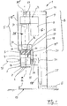
- Fig. 1 is a generally designated 1 device for dispensing ice cream.
- Such devices 1 are (similar DE 28 13 349 ) to equip a pot-shaped reservoir 2, in which an ice portion, not shown, is filled.
- the storage container 2 is supported in the vicinity of a displaceable pressing piston 3.
- an actuator 5 having plunger 3 is displaced in a stroke direction according to arrow H, while the ice cream in the reservoir 2 pressed through respective openings 6 in the container bottom 7 and then the ice cream can be taken in the form of spaghetti ice cream in a Servier disposer, not shown ,
- the device 1 is designed as a structural unit B, which in the region of the plunger 3 one with an electric cylinder 25 (FIG. Fig. 1 ) provided actuator 5 has.
- This only one electrical connection E requiring assembly B has an improved and substantially closed housing part 9, in which all the components are optimally integrated.
- the unit B at almost any application with only one electrical connection E operable and additional compressors with control lines u.
- Additional parts outside the housing 9 are unnecessary.
- the assembly B is both the demands for low production costs and increasing hygiene requirements.
- the standard electric cylinder 25 has in the closed design an electric motor 8, a gear 26 and connectable to the plunger 3 lifting part K, said assembly by surrounding walls ( Fig. 5 ) has no connection to the interior G of the housing 9.
- the concept of the compact unit B is based on the fact that in the region of the actuator 5, the movable plunger 3 and a reservoir 2 when pressing the ice supporting receiving part 4 respective releasable connections are provided as a holder.
- this detachable connection is particular achieved by a screw 10.
- the receiving part 4 can be connected by a screw 11 to the housing 9 so that a simple separation in this functional area is possible, however, an accidental entry of ice cream o. The like. In the housing interior G is prevented.
- this intended for processing food device 1 in the region of the housing 9 each made of stainless steel sheet side wall parts 12, 13, a corresponding cover part 14 and a bottom part 15 has.
- These stainless steel parts form an overall compact unit, it being conceivable to form substantially one-piece wall parts of high intrinsic stability by repeated bending of a semifinished sheet metal product.
- this material-saving construction is designed so that by mounting the wall parts to each other, the installation position of the actuator 5 (FIG. Fig. 1 . Fig. 4 ) and / or partitions 37 ", 39 ( Fig. 5 ) the entire unit B is stable.
- the bottom part 15 is in the form of a drip tray 16 (FIG. Fig. 4 ) are designed so that the in use position on this drip tray 16 components for the pressing of the spaghetti ice are completely under attack and thus an unwanted escape of ice cream residues is prevented from the environment.
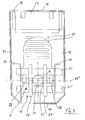
- a bracket 17 (FIG. Fig. 3 ), which has on the wall parts 12, 13 and a rear wall 18 held support legs 19, 20. Between these support legs 19, 20 preferably two cross members extend 21, 21 ', where the one vertical vertical axis M defining actuator 5 is fixed. Shown is a support eye 22 for the electric cylinder 25 provided as a drive cylinder, which is held on a retaining bolt 22 '. This in turn has respective end clamping screws 23, 23 'for mounting on respective longitudinal webs 24, 24'. This is achieved that the actuator 5 in the transverse axis M 'is also pendulum suspension.
- a second embodiment of the holder 17 ' ( Fig. 5 ) is provided that the electric cylinder 25 by respective connecting screws 19 ', 20' o. The like. Elements with the support plate 37 'is connected. In order for a releasable fixation can be achieved, wherein the upper bracket 17 ( Fig. 1 ) can be dispensable.
- Fig. 1 and 3 illustrates that in which also in areas 18 ', 18 "of a front wall plate largely closed housing part 9 both connected to the electric motor 8 electric cylinder 25 of the plunger 3 and the electric motor 8 to the electric cylinder 25 connecting gear part 26 and a control transformer 27th and a fan 28 are integrated, thus providing a compact unit with the optimum size of the shell part 9 which is effective as a shell mold
- a horizontal support plate 37 is additionally provided between the parts 18 "and 18 '" of the front wall Electric cylinder 25 receives through a stabilizing plate 38 and thus covers this area in addition.
- the plunger 3 in the region of the electric cylinder 25 respective control of the stroke (arrow H) provided end position sensors 29 and 30, which are mounted as standard on this assembly.
- These elements of the actuator 5, which can be provided as per se known per se, can be optimally integrated into the stainless steel housing 9 in the device 1 according to the invention, so that a particularly low-noise function of the assembly B is achieved with a small space requirement.
- a position measuring system or the like is also conceivable.
- an additional signal generator 31 is provided which cooperates in an appropriate embodiment with the actuator 5 and the electric motor 8 of the plunger 3.
- the signal generator 31 is actuated. Thereafter, the lowering movement is carried out according to arrow H automatically, the plunger 3 is controlled according to the end position sensors 29 and 30 and lowered from an upper position or moved back into this.
- a proximity switch 34 is provided as a signal generator in the region of the receiving part 4, which is activated with the retaining pin 35 of the storage container 2.
- a non-contact activation of the switch 34 is so in the wall area 18 "positioned that a largely gap-free surface to the upstream functional area out there.
- the plunger 3 With the drive according to the invention via the electric lifting cylinder 25, the plunger 3 can be moved with substantially variable pressing speeds, since in the region of the electric motor 8 and the transmission 26, a rapid adaptation to different speeds is possible. In particular, the movement of the plunger 3 is also infinitely variable.
- the housing part 9 which forms a closed structural unit is in the region of at least one of its walls with respective ventilation openings 36 (FIG. Fig. 3 ), these openings may also be provided in the region of the rear wall 18 and the side walls 12 or 13.
- the assembly B according to the invention is easy to transport with its space-saving and lightweight design, with the molded by folding the stainless steel sheet wall parts 12, 13, 14, 15, 18 a largely integral housing part 9 can be formed, which also has a visually appealing design.
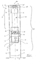
- Fig. 4 is a generally designated 1 'device for dispensing ice cream in a second embodiment. Also the concept of the compact unit B according to Fig. 4 is based on the fact that in the area of the actuator 5, the movable plunger 3 and the reservoir 2 when pressing the Ice supporting receiving part 4 respective releasable connections are provided as a holder.
- the actuator 5 may advantageously be provided in the region of its connected to the gear 26 and the motor 8 electric cylinder 25 with a ball-roller spindle not shown as the lifting part K. In its place, a pneumatic or hydraulic drive is conceivable. In the area of a control part 56, an operation of the actuator 5 is possible, which is achieved by appropriate speed settings of the pressing movement of the piston 3 (arrow H) adaptation to varying consistencies of the ice in the reservoir 2.
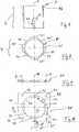
- Fig. 5 to 10 show respective enlarged representations a special structure of the component connection 11 ', which may be provided in principle as a screw and / or clamp connection.
- the receiving part 4 in the region of a support plate 37 '- which in turn between two wall parts 39, 40 of the housing 9 is held - by a connector, not shown.
- a screw 41 which acts transversely to the longitudinal center plane M or the like.
- Clamping part (s) (arrow A, Fig. 5 ) is a fixation possible.
- the upper edge region of the receiving part 4 can be detected by means of the clamping screw 41 at R and pressed in the clamping direction A against a located in the region of the wall portion 39 contact element 52.
- Fig. 6 to 10 illustrate that the receiving part 4 at the top in the installed position a profile projection P ( Fig. 6 ), which with a housing-side or in the region of the support plate 37 'provided counter-profile 42 ( Fig. 10 ) is connectable.
- this is in Fig. 6 formed profile connection in the manner of a bayonet closure, so that the receiving part 4 in a vertical connection direction (arrow B ', Fig. 6 ) in the complementary profiled passage opening 43 of the support plate 37 'displaceable and by a corresponding pivoting movement (arrow D, Fig. 6 ) in the range of profile projection P and counter profile 42 is locked or unlocked.
- the receiving part 4 with a profile projection P having ring member 46 ( Fig. 8 ), which is welded on the upper side with the receiving part 4.
- the counter profile 42 is formed in the effective as a receiving plate support plate 37 'or in the edge region of the opening 43 so that four receiving openings 44 and neck portions 45 are provided.
- This effective in the manner of a bayonet closure profiling is with the corresponding profiles 44 'and 45' of the receiving part 4 ( Fig. 8 ) latched and easy unlocked especially for cleaning purposes.
- an additional clamping screw 41 ( Fig. 10 ), whose Rotary movement causes a clamping action in the direction of arrow C (similar to the clamping screw 41 in FIG Fig. 4 ) and thus the receiving part 4 fixed to the support plate 37 '.
- connection 11 '( Fig. 5 ) an additional support plate 37 "be provided, so that this is additionally stiffened when operating the device 1 'portion.”
- the support plate 37 "extends between the wall parts 39 and 40 of the housing 9 and has a provided below the actuator 5 passage opening 55, which is closed with a seal not shown so that the interior G of the housing 9 is separated from the functional ice filling area F and unwanted contamination of the system interior are avoided.
- the housing 9 held on the support plate 37 is advantageously dimensioned so that at this the support plate 37 'by means of their holding openings 53 (FIGS. Fig. 10 ) through bolts (not shown) o. The like. Connecting means in the range S ( Fig. 6 ) is determinable.
- the storage container 2 ( Fig. 4 ) has a handle 48, the support arm 49 is vertically insertable into a provided in the receiving part 4 receiving groove 50 and radially displaceable towards a transverse groove leg 51. In this position, when pressing ice (ram movement according to arrow H, Fig. 4 ) reaches a stable connection of reservoir 2 and receiving part 4 and ensures the contactless contact between the holding pin 35 and proximity switch 34 ( Fig. 5 ).
- the above-described device 1 ' is designed so that a complete separation of the ice-dispensing parts from the base unit provided as an operator control unit 13 by a simple disassembly. Fig. 2 ) is possible.
- the requirements provided by the conditions of food hygiene can be met safely.
- the receiving part 4 in the connection region at 11 'from the housing 9 are separated, the plunger 3 is in the range T ( Fig. 5 ) detachable from the actuator 5 and the bottom-side drip tray 16 can also be easily cleaned.
- the ice receiving reservoir 2 ( Fig. 4 ) has in the region of its container bottom 7 also releasable connections, wherein an adaptable to the desired ice shaping insert plate 57 (with the openings 6) is held by a threaded ring 58 so that a quick disassembly and cleaning is possible here. All items can be a dishwasher o. The like. Are supplied and after cleaning a simple assembly of the unit B in the output area F is possible.
Landscapes
- Life Sciences & Earth Sciences (AREA)
- Chemical & Material Sciences (AREA)
- Engineering & Computer Science (AREA)
- Food Science & Technology (AREA)
- Polymers & Plastics (AREA)
- Confectionery (AREA)
Priority Applications (1)
| Application Number | Priority Date | Filing Date | Title |
|---|---|---|---|
| PL07724472T PL2010002T3 (pl) | 2006-04-25 | 2007-04-23 | Urządzenie do wydawania lodów |
Applications Claiming Priority (3)
| Application Number | Priority Date | Filing Date | Title |
|---|---|---|---|
| DE200610019626 DE102006019626A1 (de) | 2006-04-25 | 2006-04-25 | Vorrichtung zum Ausgeben von Speiseeis |
| DE200620008741 DE202006008741U1 (de) | 2006-05-31 | 2006-05-31 | Vorrichtung zum Ausgeben von Speiseeis |
| PCT/EP2007/003542 WO2007121967A2 (de) | 2006-04-25 | 2007-04-23 | Vorrichtung zum ausgeben von speiseeis |
Publications (2)
| Publication Number | Publication Date |
|---|---|
| EP2010002A2 EP2010002A2 (de) | 2009-01-07 |
| EP2010002B1 true EP2010002B1 (de) | 2009-09-23 |
Family
ID=38440199
Family Applications (1)
| Application Number | Title | Priority Date | Filing Date |
|---|---|---|---|
| EP07724472A Not-in-force EP2010002B1 (de) | 2006-04-25 | 2007-04-23 | Vorrichtung zum ausgeben von speiseeis |
Country Status (6)
| Country | Link |
|---|---|
| EP (1) | EP2010002B1 (pl) |
| AT (1) | ATE443450T1 (pl) |
| DE (1) | DE502007001591D1 (pl) |
| DK (1) | DK2010002T3 (pl) |
| PL (1) | PL2010002T3 (pl) |
| WO (1) | WO2007121967A2 (pl) |
Families Citing this family (6)
| Publication number | Priority date | Publication date | Assignee | Title |
|---|---|---|---|---|
| CN101401608B (zh) * | 2008-09-24 | 2011-03-09 | 宁波鑫盛达机械有限公司 | 冰淇淋制作上旋转装置 |
| GB0916618D0 (en) * | 2009-09-22 | 2009-11-04 | Mcgill Tech Ltd | Apparatus for dispensing food product |
| DE102019127504B3 (de) * | 2019-10-11 | 2021-04-01 | CryonCo GmbH & Co. KG | Vorrichtung zum Herstellen von Trockeneis |
| EP4014747A1 (de) * | 2020-12-17 | 2022-06-22 | Oliver Grohe | System und verfahren zur herstellung von spaghettieis und zugehörige spaghettieismaschine und eiskartusche |
| KR20250162829A (ko) | 2023-03-03 | 2025-11-19 | 샤크닌자 오퍼레이팅 엘엘씨 | 마이크로 퓨레 기계용 압출 어셈블리 |
| US12207669B1 (en) | 2023-08-28 | 2025-01-28 | Sharkninja Operating Llc | Nozzle control assemblies for a micro-puree machine |
Family Cites Families (7)
| Publication number | Priority date | Publication date | Assignee | Title |
|---|---|---|---|---|
| DE7418128U (de) * | 1974-10-03 | Kasper W | Vorrichtung zur Herstellung und zur Abgabe von Speiseeis | |
| US3984033A (en) * | 1975-12-29 | 1976-10-05 | Wear-Ever Aluminum, Inc. | Electric gun for dispensing of comestibles |
| IT1209441B (it) * | 1977-03-29 | 1989-08-30 | B M Dei F Lli Bravo Genesio Fr | Macchina per la formazione di spaghetti di gelato. |
| EP0128258A1 (de) * | 1983-06-09 | 1984-12-19 | BOVO S.a.s. dei F.lli Pillon Claudio e Paolo & C. | Maschine für die Formgebung von Nahrungsmitteln |
| DE3542290A1 (de) * | 1985-11-29 | 1987-06-04 | Luigino Casagrande | Vorrichtung zum ausformen von plastisch verformbaren massen |
| IT211889Z2 (it) * | 1987-09-11 | 1989-05-25 | Bravo Spa | Macchina perfezionata per laproduzione di spaghetti di gelato. |
| US5820892A (en) * | 1996-09-27 | 1998-10-13 | Lauer; James D. | Food extrusion assembly |
-
2007
- 2007-04-23 AT AT07724472T patent/ATE443450T1/de active
- 2007-04-23 DE DE502007001591T patent/DE502007001591D1/de active Active
- 2007-04-23 WO PCT/EP2007/003542 patent/WO2007121967A2/de not_active Ceased
- 2007-04-23 PL PL07724472T patent/PL2010002T3/pl unknown
- 2007-04-23 DK DK07724472T patent/DK2010002T3/da active
- 2007-04-23 EP EP07724472A patent/EP2010002B1/de not_active Not-in-force
Also Published As
| Publication number | Publication date |
|---|---|
| DE502007001591D1 (de) | 2009-11-05 |
| WO2007121967A3 (de) | 2008-02-07 |
| ATE443450T1 (de) | 2009-10-15 |
| WO2007121967A2 (de) | 2007-11-01 |
| DK2010002T3 (da) | 2009-12-21 |
| PL2010002T3 (pl) | 2010-02-26 |
| EP2010002A2 (de) | 2009-01-07 |
Similar Documents
| Publication | Publication Date | Title |
|---|---|---|
| EP2010002B1 (de) | Vorrichtung zum ausgeben von speiseeis | |
| DE19907057A1 (de) | Dunstabzugsvorrichtung, angeordnet im Bereich neben offenen Garungsbereichen | |
| EP1774883B1 (de) | Kaffeemaschine | |
| EP1829656B1 (de) | Holzbearbeitungsmaschine | |
| EP3692306A1 (de) | Dunstabzugsvorrichtung | |
| DE3706351C3 (de) | Durch einen Druckluft-Kolbenmotor angetriebene Flüssigkeits-Kolbenpumpe | |
| DE102004023964B3 (de) | Kaffeemaschinenautomat | |
| DE2000395A1 (de) | Knet- und Mischmaschine fuer Fleisch- und Wurstwaren | |
| EP3048936B1 (de) | Vorrichtung zum zubereiten von speisen | |
| DE2439417B2 (de) | Aufbrühvorrichtung für warme Getränke | |
| DE3214818C2 (de) | Grillgerät mit einem eine darin angeordnete Tragscheibe aufweisenden Gehäuse | |
| EP2036467B1 (de) | Perkolator zur Zubereitung von Brühgetränken | |
| DE8606633U1 (de) | Vorrichtung zum Zerkleinern, Mischen, Kneten und Schlagen von Gut | |
| EP0598246B1 (de) | Zahntechnischer Arbeitsplatz mit einem Arbeitstisch und einer Absaugeinrichtung mit einem Filtergerät | |
| WO2004018371A1 (de) | Pressstempelmechanismus einer glasformmaschine | |
| DE29512854U1 (de) | Drehmesser mit Absaugung für Fleisch oder Fett | |
| EP0713230B1 (de) | Variabler Kondensator | |
| DE202006019866U1 (de) | Vorrichtung zum Ausgeben von Speiseeis | |
| DE202006008741U1 (de) | Vorrichtung zum Ausgeben von Speiseeis | |
| DE3545226A1 (de) | Elektrisch betriebenes geraet fuer die bearbeitung und zubereitung von nahrungsmitteln aller art | |
| DE102006019626A1 (de) | Vorrichtung zum Ausgeben von Speiseeis | |
| DE2710300C2 (de) | Haushaltgerät, zum Zerkleinern von Lebensmitteln, insbesondere von Fleisch, Zwiebeln o.dgl. | |
| DE9111211U1 (de) | Rundwirkvorrichtung für Teigstücke | |
| AT245753B (de) | Halterung für eine Schneid- und Mischmaschine | |
| DE102006021981B4 (de) | Spritzpistole |
Legal Events
| Date | Code | Title | Description |
|---|---|---|---|
| PUAI | Public reference made under article 153(3) epc to a published international application that has entered the european phase |
Free format text: ORIGINAL CODE: 0009012 |
|
| 17P | Request for examination filed |
Effective date: 20081028 |
|
| AK | Designated contracting states |
Kind code of ref document: A2 Designated state(s): AT BE BG CH CY CZ DE DK EE ES FI FR GB GR HU IE IS IT LI LT LU LV MC MT NL PL PT RO SE SI SK TR |
|
| AX | Request for extension of the european patent |
Extension state: AL BA HR MK RS |
|
| GRAP | Despatch of communication of intention to grant a patent |
Free format text: ORIGINAL CODE: EPIDOSNIGR1 |
|
| DAX | Request for extension of the european patent (deleted) | ||
| GRAS | Grant fee paid |
Free format text: ORIGINAL CODE: EPIDOSNIGR3 |
|
| GRAA | (expected) grant |
Free format text: ORIGINAL CODE: 0009210 |
|
| AK | Designated contracting states |
Kind code of ref document: B1 Designated state(s): AT BE BG CH CY CZ DE DK EE ES FI FR GB GR HU IE IS IT LI LT LU LV MC MT NL PL PT RO SE SI SK TR |
|
| REG | Reference to a national code |
Ref country code: GB Ref legal event code: FG4D Free format text: NOT ENGLISH |
|
| REG | Reference to a national code |
Ref country code: CH Ref legal event code: EP Ref country code: CH Ref legal event code: NV Representative=s name: SCHNEIDER FELDMANN AG PATENT- UND MARKENANWAELTE |
|
| REG | Reference to a national code |
Ref country code: IE Ref legal event code: FG4D |
|
| REF | Corresponds to: |
Ref document number: 502007001591 Country of ref document: DE Date of ref document: 20091105 Kind code of ref document: P |
|
| REG | Reference to a national code |
Ref country code: DK Ref legal event code: T3 |
|
| REG | Reference to a national code |
Ref country code: SE Ref legal event code: TRGR |
|
| PG25 | Lapsed in a contracting state [announced via postgrant information from national office to epo] |
Ref country code: LT Free format text: LAPSE BECAUSE OF FAILURE TO SUBMIT A TRANSLATION OF THE DESCRIPTION OR TO PAY THE FEE WITHIN THE PRESCRIBED TIME-LIMIT Effective date: 20090923 Ref country code: FI Free format text: LAPSE BECAUSE OF FAILURE TO SUBMIT A TRANSLATION OF THE DESCRIPTION OR TO PAY THE FEE WITHIN THE PRESCRIBED TIME-LIMIT Effective date: 20090923 |
|
| LTIE | Lt: invalidation of european patent or patent extension |
Effective date: 20090923 |
|
| PG25 | Lapsed in a contracting state [announced via postgrant information from national office to epo] |
Ref country code: LV Free format text: LAPSE BECAUSE OF FAILURE TO SUBMIT A TRANSLATION OF THE DESCRIPTION OR TO PAY THE FEE WITHIN THE PRESCRIBED TIME-LIMIT Effective date: 20090923 Ref country code: SI Free format text: LAPSE BECAUSE OF FAILURE TO SUBMIT A TRANSLATION OF THE DESCRIPTION OR TO PAY THE FEE WITHIN THE PRESCRIBED TIME-LIMIT Effective date: 20090923 |
|
| REG | Reference to a national code |
Ref country code: PL Ref legal event code: T3 |
|
| PG25 | Lapsed in a contracting state [announced via postgrant information from national office to epo] |
Ref country code: CY Free format text: LAPSE BECAUSE OF FAILURE TO SUBMIT A TRANSLATION OF THE DESCRIPTION OR TO PAY THE FEE WITHIN THE PRESCRIBED TIME-LIMIT Effective date: 20090923 |
|
| REG | Reference to a national code |
Ref country code: IE Ref legal event code: FD4D |
|
| PG25 | Lapsed in a contracting state [announced via postgrant information from national office to epo] |
Ref country code: IS Free format text: LAPSE BECAUSE OF FAILURE TO SUBMIT A TRANSLATION OF THE DESCRIPTION OR TO PAY THE FEE WITHIN THE PRESCRIBED TIME-LIMIT Effective date: 20100123 Ref country code: PT Free format text: LAPSE BECAUSE OF FAILURE TO SUBMIT A TRANSLATION OF THE DESCRIPTION OR TO PAY THE FEE WITHIN THE PRESCRIBED TIME-LIMIT Effective date: 20100125 Ref country code: IE Free format text: LAPSE BECAUSE OF FAILURE TO SUBMIT A TRANSLATION OF THE DESCRIPTION OR TO PAY THE FEE WITHIN THE PRESCRIBED TIME-LIMIT Effective date: 20090923 Ref country code: RO Free format text: LAPSE BECAUSE OF FAILURE TO SUBMIT A TRANSLATION OF THE DESCRIPTION OR TO PAY THE FEE WITHIN THE PRESCRIBED TIME-LIMIT Effective date: 20090923 Ref country code: ES Free format text: LAPSE BECAUSE OF FAILURE TO SUBMIT A TRANSLATION OF THE DESCRIPTION OR TO PAY THE FEE WITHIN THE PRESCRIBED TIME-LIMIT Effective date: 20100103 Ref country code: EE Free format text: LAPSE BECAUSE OF FAILURE TO SUBMIT A TRANSLATION OF THE DESCRIPTION OR TO PAY THE FEE WITHIN THE PRESCRIBED TIME-LIMIT Effective date: 20090923 |
|
| PG25 | Lapsed in a contracting state [announced via postgrant information from national office to epo] |
Ref country code: SK Free format text: LAPSE BECAUSE OF FAILURE TO SUBMIT A TRANSLATION OF THE DESCRIPTION OR TO PAY THE FEE WITHIN THE PRESCRIBED TIME-LIMIT Effective date: 20090923 |
|
| PLBE | No opposition filed within time limit |
Free format text: ORIGINAL CODE: 0009261 |
|
| STAA | Information on the status of an ep patent application or granted ep patent |
Free format text: STATUS: NO OPPOSITION FILED WITHIN TIME LIMIT |
|
| 26N | No opposition filed |
Effective date: 20100624 |
|
| PG25 | Lapsed in a contracting state [announced via postgrant information from national office to epo] |
Ref country code: GR Free format text: LAPSE BECAUSE OF FAILURE TO SUBMIT A TRANSLATION OF THE DESCRIPTION OR TO PAY THE FEE WITHIN THE PRESCRIBED TIME-LIMIT Effective date: 20091224 |
|
| PG25 | Lapsed in a contracting state [announced via postgrant information from national office to epo] |
Ref country code: MC Free format text: LAPSE BECAUSE OF NON-PAYMENT OF DUE FEES Effective date: 20100430 |
|
| PG25 | Lapsed in a contracting state [announced via postgrant information from national office to epo] |
Ref country code: IT Free format text: LAPSE BECAUSE OF NON-PAYMENT OF DUE FEES Effective date: 20100423 |
|
| PG25 | Lapsed in a contracting state [announced via postgrant information from national office to epo] |
Ref country code: MT Free format text: LAPSE BECAUSE OF FAILURE TO SUBMIT A TRANSLATION OF THE DESCRIPTION OR TO PAY THE FEE WITHIN THE PRESCRIBED TIME-LIMIT Effective date: 20090923 |
|
| PG25 | Lapsed in a contracting state [announced via postgrant information from national office to epo] |
Ref country code: LU Free format text: LAPSE BECAUSE OF NON-PAYMENT OF DUE FEES Effective date: 20100423 Ref country code: HU Free format text: LAPSE BECAUSE OF FAILURE TO SUBMIT A TRANSLATION OF THE DESCRIPTION OR TO PAY THE FEE WITHIN THE PRESCRIBED TIME-LIMIT Effective date: 20100324 Ref country code: BG Free format text: LAPSE BECAUSE OF FAILURE TO SUBMIT A TRANSLATION OF THE DESCRIPTION OR TO PAY THE FEE WITHIN THE PRESCRIBED TIME-LIMIT Effective date: 20090923 |
|
| PG25 | Lapsed in a contracting state [announced via postgrant information from national office to epo] |
Ref country code: TR Free format text: LAPSE BECAUSE OF FAILURE TO SUBMIT A TRANSLATION OF THE DESCRIPTION OR TO PAY THE FEE WITHIN THE PRESCRIBED TIME-LIMIT Effective date: 20090923 |
|
| PGFP | Annual fee paid to national office [announced via postgrant information from national office to epo] |
Ref country code: CZ Payment date: 20140114 Year of fee payment: 8 |
|
| PGFP | Annual fee paid to national office [announced via postgrant information from national office to epo] |
Ref country code: GB Payment date: 20140422 Year of fee payment: 8 |
|
| PGFP | Annual fee paid to national office [announced via postgrant information from national office to epo] |
Ref country code: IT Payment date: 20140408 Year of fee payment: 8 Ref country code: FR Payment date: 20140428 Year of fee payment: 8 Ref country code: SE Payment date: 20140422 Year of fee payment: 8 Ref country code: AT Payment date: 20140425 Year of fee payment: 8 Ref country code: NL Payment date: 20140430 Year of fee payment: 8 |
|
| PGFP | Annual fee paid to national office [announced via postgrant information from national office to epo] |
Ref country code: PL Payment date: 20140311 Year of fee payment: 8 Ref country code: BE Payment date: 20140429 Year of fee payment: 8 Ref country code: DK Payment date: 20140415 Year of fee payment: 8 |
|
| PGFP | Annual fee paid to national office [announced via postgrant information from national office to epo] |
Ref country code: CH Payment date: 20140728 Year of fee payment: 8 |
|
| REG | Reference to a national code |
Ref country code: DK Ref legal event code: EBP Effective date: 20150430 |
|
| REG | Reference to a national code |
Ref country code: CH Ref legal event code: PL |
|
| REG | Reference to a national code |
Ref country code: SE Ref legal event code: EUG Ref country code: AT Ref legal event code: MM01 Ref document number: 443450 Country of ref document: AT Kind code of ref document: T Effective date: 20150423 |
|
| GBPC | Gb: european patent ceased through non-payment of renewal fee |
Effective date: 20150423 |
|
| REG | Reference to a national code |
Ref country code: NL Ref legal event code: MM Effective date: 20150501 |
|
| PG25 | Lapsed in a contracting state [announced via postgrant information from national office to epo] |
Ref country code: CH Free format text: LAPSE BECAUSE OF NON-PAYMENT OF DUE FEES Effective date: 20150430 Ref country code: GB Free format text: LAPSE BECAUSE OF NON-PAYMENT OF DUE FEES Effective date: 20150423 Ref country code: LI Free format text: LAPSE BECAUSE OF NON-PAYMENT OF DUE FEES Effective date: 20150430 Ref country code: IT Free format text: LAPSE BECAUSE OF NON-PAYMENT OF DUE FEES Effective date: 20150423 |
|
| REG | Reference to a national code |
Ref country code: FR Ref legal event code: ST Effective date: 20151231 |
|
| PG25 | Lapsed in a contracting state [announced via postgrant information from national office to epo] |
Ref country code: AT Free format text: LAPSE BECAUSE OF NON-PAYMENT OF DUE FEES Effective date: 20150423 Ref country code: CZ Free format text: LAPSE BECAUSE OF NON-PAYMENT OF DUE FEES Effective date: 20150423 Ref country code: FR Free format text: LAPSE BECAUSE OF NON-PAYMENT OF DUE FEES Effective date: 20150430 Ref country code: SE Free format text: LAPSE BECAUSE OF NON-PAYMENT OF DUE FEES Effective date: 20150424 |
|
| PG25 | Lapsed in a contracting state [announced via postgrant information from national office to epo] |
Ref country code: NL Free format text: LAPSE BECAUSE OF NON-PAYMENT OF DUE FEES Effective date: 20150501 |
|
| PG25 | Lapsed in a contracting state [announced via postgrant information from national office to epo] |
Ref country code: DK Free format text: LAPSE BECAUSE OF NON-PAYMENT OF DUE FEES Effective date: 20150430 |
|
| PG25 | Lapsed in a contracting state [announced via postgrant information from national office to epo] |
Ref country code: PL Free format text: LAPSE BECAUSE OF NON-PAYMENT OF DUE FEES Effective date: 20150423 |
|
| PG25 | Lapsed in a contracting state [announced via postgrant information from national office to epo] |
Ref country code: BE Free format text: LAPSE BECAUSE OF NON-PAYMENT OF DUE FEES Effective date: 20150430 |
|
| PGFP | Annual fee paid to national office [announced via postgrant information from national office to epo] |
Ref country code: DE Payment date: 20180115 Year of fee payment: 12 |
|
| REG | Reference to a national code |
Ref country code: DE Ref legal event code: R119 Ref document number: 502007001591 Country of ref document: DE |
|
| PG25 | Lapsed in a contracting state [announced via postgrant information from national office to epo] |
Ref country code: DE Free format text: LAPSE BECAUSE OF NON-PAYMENT OF DUE FEES Effective date: 20191101 |