EP2010002B1 - Vorrichtung zum ausgeben von speiseeis - Google Patents
Vorrichtung zum ausgeben von speiseeis Download PDFInfo
- Publication number
- EP2010002B1 EP2010002B1 EP07724472A EP07724472A EP2010002B1 EP 2010002 B1 EP2010002 B1 EP 2010002B1 EP 07724472 A EP07724472 A EP 07724472A EP 07724472 A EP07724472 A EP 07724472A EP 2010002 B1 EP2010002 B1 EP 2010002B1
- Authority
- EP
- European Patent Office
- Prior art keywords
- receiving part
- housing
- pressure
- assembly
- region
- Prior art date
- Legal status (The legal status is an assumption and is not a legal conclusion. Google has not performed a legal analysis and makes no representation as to the accuracy of the status listed.)
- Not-in-force
Links
Images


Classifications
-
- A—HUMAN NECESSITIES
- A23—FOODS OR FOODSTUFFS; TREATMENT THEREOF, NOT COVERED BY OTHER CLASSES
- A23G—COCOA; COCOA PRODUCTS, e.g. CHOCOLATE; SUBSTITUTES FOR COCOA OR COCOA PRODUCTS; CONFECTIONERY; CHEWING GUM; ICE-CREAM; PREPARATION THEREOF
- A23G9/00—Frozen sweets, e.g. ice confectionery, ice-cream; Mixtures therefor
- A23G9/04—Production of frozen sweets, e.g. ice-cream
- A23G9/22—Details, component parts or accessories of apparatus insofar as not peculiar to a single one of the preceding groups
- A23G9/28—Details, component parts or accessories of apparatus insofar as not peculiar to a single one of the preceding groups for portioning or dispensing
- A23G9/281—Details, component parts or accessories of apparatus insofar as not peculiar to a single one of the preceding groups for portioning or dispensing at the discharge end of freezing chambers
- A23G9/285—Details, component parts or accessories of apparatus insofar as not peculiar to a single one of the preceding groups for portioning or dispensing at the discharge end of freezing chambers for extruding strips, cutting blocks and manipulating cut blocks
Definitions
- the invention relates to a device for dispensing ice cream, in particular in the form of spaghetti ice, according to the preamble of claim 1.
- a cup-shaped reservoir is filled with an ice cream portion and squeezed through bottom openings of the reservoir, so that the ice is shaped like spaghetti noodles.
- This device has a tubular stand on which on the one hand the reservoir and on the other hand a hand lever are held, by means of which a pressure piece in the reservoir can be pivoted.
- DE 22 14 023 and DE 26 25 906 are machines for processing ice cream o.
- Foods known, with a piston press and effective as a nozzle tool reservoir are provided and from this the ice cream, the dough o. The like, is pressed out largely automatically.
- DE 28 13 349 shows a generic ice cream machine in which a plunger of a reciprocating press is provided with a drive shaft which is coupled by means of an open inside the housing interior threaded connection directly to a drive motor, so that an axial displacement of the plunger is possible.
- This large construction in coaxial design is by a variety of items less easy to assemble or disassembly, has high wear and requires a lot of time in cleaning.
- the housing are in the interior leading gap areas by exposed contact elements, snaps u.
- Components required so that there is a high risk of contamination and thus there is a failure-prone and strict hygiene requirements not appropriate design.
- the invention is concerned with the problem of providing a device for dispensing spaghetti ice, whose reduced noise pollution leading Preßkolbenantrieb can be integrated into a producible with little technical effort and compact housing part and the overall concept of the device with low space requirements a largely self-sufficient use at different places of application as well as the fulfillment of high demands on the hygiene safety.
- the device for dispensing spaghetti ice is designed according to the invention as a self-contained unit with a stainless steel sheet housing.
- an electrically operated drive in the form of a standard Etektrozylinders a particularly space-saving and optimally adaptable to the automatic pressing drive for displacement of the plunger is provided, with only one electrical connection is required in this concept and the system of compressed air o. The like remains.
- the few items can be installed compactly in a largely closed housing part, so that this device in the form of an ice press only requires the electrical connection and can form a network-independent self-sufficient system at largely any application with a battery-powered electric cylinder.
- the device structure has a sheet metal construction which is closed as an envelope contour as a housing, so that an easily transportable structural unit, which enables easy handling with the automatically interacting assemblies, is provided.
- This also fulfills high requirements for hygiene safety, as the stainless steel sheet design ensures optimum protection against soiling and easy cleaning is possible.
- the device has an optimum combination of an electric cylinder which can be provided as a series component with the stainless steel sheet metal housing which is structurally matched to it, whose peripheral contour forms a largely gap-free shell through the control modules integrated into the interior, which is extremely compact with the one-piece wall in the region of the support leg is.
- the system is overall pollution-resistant and has a high standard of hygiene.
- the respective assemblies of the device in the range of the actuator, the displaceable with the electric cylinder plunger and the receiving part for the reservoir are designed so that a simple disassembly is possible for cleaning purposes.
- the plunger with little effort from the drive cylinder is releasable, so that even less skilled auxiliaries a simple cleaning and the hygiene requirements appropriate handling of the device is possible.
- the housing part made of stainless steel sheet all components are integrated and integrally formed with the housing bottom part of an additional drip tray is formed so that the device is optimally supported on a pad and thereby an unwanted escape of ice cream residue is avoided.
- the parts are connected by screw connections in the region between a support plate and the upper end of the receiving part. It is also provided to fix these removable and easy-to-clean parts by a connector in the manner of a bayonet closure. This achieves a particularly simple and quickly operable holder and the disassembled stainless steel parts can be efficiently fed to a machine cleaning.
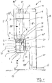
- Fig. 1 is a generally designated 1 device for dispensing ice cream.
- Such devices 1 are (similar DE 28 13 349 ) to equip a pot-shaped reservoir 2, in which an ice portion, not shown, is filled.
- the storage container 2 is supported in the vicinity of a displaceable pressing piston 3.
- an actuator 5 having plunger 3 is displaced in a stroke direction according to arrow H, while the ice cream in the reservoir 2 pressed through respective openings 6 in the container bottom 7 and then the ice cream can be taken in the form of spaghetti ice cream in a Servier disposer, not shown ,
- the device 1 is designed as a structural unit B, which in the region of the plunger 3 one with an electric cylinder 25 (FIG. Fig. 1 ) provided actuator 5 has.
- This only one electrical connection E requiring assembly B has an improved and substantially closed housing part 9, in which all the components are optimally integrated.
- the unit B at almost any application with only one electrical connection E operable and additional compressors with control lines u.
- Additional parts outside the housing 9 are unnecessary.
- the assembly B is both the demands for low production costs and increasing hygiene requirements.
- the standard electric cylinder 25 has in the closed design an electric motor 8, a gear 26 and connectable to the plunger 3 lifting part K, said assembly by surrounding walls ( Fig. 5 ) has no connection to the interior G of the housing 9.
- the concept of the compact unit B is based on the fact that in the region of the actuator 5, the movable plunger 3 and a reservoir 2 when pressing the ice supporting receiving part 4 respective releasable connections are provided as a holder.
- this detachable connection is particular achieved by a screw 10.
- the receiving part 4 can be connected by a screw 11 to the housing 9 so that a simple separation in this functional area is possible, however, an accidental entry of ice cream o. The like. In the housing interior G is prevented.
- this intended for processing food device 1 in the region of the housing 9 each made of stainless steel sheet side wall parts 12, 13, a corresponding cover part 14 and a bottom part 15 has.
- These stainless steel parts form an overall compact unit, it being conceivable to form substantially one-piece wall parts of high intrinsic stability by repeated bending of a semifinished sheet metal product.
- this material-saving construction is designed so that by mounting the wall parts to each other, the installation position of the actuator 5 (FIG. Fig. 1 . Fig. 4 ) and / or partitions 37 ", 39 ( Fig. 5 ) the entire unit B is stable.
- the bottom part 15 is in the form of a drip tray 16 (FIG. Fig. 4 ) are designed so that the in use position on this drip tray 16 components for the pressing of the spaghetti ice are completely under attack and thus an unwanted escape of ice cream residues is prevented from the environment.
- a bracket 17 (FIG. Fig. 3 ), which has on the wall parts 12, 13 and a rear wall 18 held support legs 19, 20. Between these support legs 19, 20 preferably two cross members extend 21, 21 ', where the one vertical vertical axis M defining actuator 5 is fixed. Shown is a support eye 22 for the electric cylinder 25 provided as a drive cylinder, which is held on a retaining bolt 22 '. This in turn has respective end clamping screws 23, 23 'for mounting on respective longitudinal webs 24, 24'. This is achieved that the actuator 5 in the transverse axis M 'is also pendulum suspension.
- a second embodiment of the holder 17 ' ( Fig. 5 ) is provided that the electric cylinder 25 by respective connecting screws 19 ', 20' o. The like. Elements with the support plate 37 'is connected. In order for a releasable fixation can be achieved, wherein the upper bracket 17 ( Fig. 1 ) can be dispensable.
- Fig. 1 and 3 illustrates that in which also in areas 18 ', 18 "of a front wall plate largely closed housing part 9 both connected to the electric motor 8 electric cylinder 25 of the plunger 3 and the electric motor 8 to the electric cylinder 25 connecting gear part 26 and a control transformer 27th and a fan 28 are integrated, thus providing a compact unit with the optimum size of the shell part 9 which is effective as a shell mold
- a horizontal support plate 37 is additionally provided between the parts 18 "and 18 '" of the front wall Electric cylinder 25 receives through a stabilizing plate 38 and thus covers this area in addition.
- the plunger 3 in the region of the electric cylinder 25 respective control of the stroke (arrow H) provided end position sensors 29 and 30, which are mounted as standard on this assembly.
- These elements of the actuator 5, which can be provided as per se known per se, can be optimally integrated into the stainless steel housing 9 in the device 1 according to the invention, so that a particularly low-noise function of the assembly B is achieved with a small space requirement.
- a position measuring system or the like is also conceivable.
- an additional signal generator 31 is provided which cooperates in an appropriate embodiment with the actuator 5 and the electric motor 8 of the plunger 3.
- the signal generator 31 is actuated. Thereafter, the lowering movement is carried out according to arrow H automatically, the plunger 3 is controlled according to the end position sensors 29 and 30 and lowered from an upper position or moved back into this.
- a proximity switch 34 is provided as a signal generator in the region of the receiving part 4, which is activated with the retaining pin 35 of the storage container 2.
- a non-contact activation of the switch 34 is so in the wall area 18 "positioned that a largely gap-free surface to the upstream functional area out there.
- the plunger 3 With the drive according to the invention via the electric lifting cylinder 25, the plunger 3 can be moved with substantially variable pressing speeds, since in the region of the electric motor 8 and the transmission 26, a rapid adaptation to different speeds is possible. In particular, the movement of the plunger 3 is also infinitely variable.
- the housing part 9 which forms a closed structural unit is in the region of at least one of its walls with respective ventilation openings 36 (FIG. Fig. 3 ), these openings may also be provided in the region of the rear wall 18 and the side walls 12 or 13.
- the assembly B according to the invention is easy to transport with its space-saving and lightweight design, with the molded by folding the stainless steel sheet wall parts 12, 13, 14, 15, 18 a largely integral housing part 9 can be formed, which also has a visually appealing design.
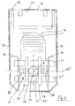
- Fig. 4 is a generally designated 1 'device for dispensing ice cream in a second embodiment. Also the concept of the compact unit B according to Fig. 4 is based on the fact that in the area of the actuator 5, the movable plunger 3 and the reservoir 2 when pressing the Ice supporting receiving part 4 respective releasable connections are provided as a holder.
- the actuator 5 may advantageously be provided in the region of its connected to the gear 26 and the motor 8 electric cylinder 25 with a ball-roller spindle not shown as the lifting part K. In its place, a pneumatic or hydraulic drive is conceivable. In the area of a control part 56, an operation of the actuator 5 is possible, which is achieved by appropriate speed settings of the pressing movement of the piston 3 (arrow H) adaptation to varying consistencies of the ice in the reservoir 2.
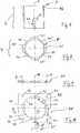
- Fig. 5 to 10 show respective enlarged representations a special structure of the component connection 11 ', which may be provided in principle as a screw and / or clamp connection.
- the receiving part 4 in the region of a support plate 37 '- which in turn between two wall parts 39, 40 of the housing 9 is held - by a connector, not shown.
- a screw 41 which acts transversely to the longitudinal center plane M or the like.
- Clamping part (s) (arrow A, Fig. 5 ) is a fixation possible.
- the upper edge region of the receiving part 4 can be detected by means of the clamping screw 41 at R and pressed in the clamping direction A against a located in the region of the wall portion 39 contact element 52.
- Fig. 6 to 10 illustrate that the receiving part 4 at the top in the installed position a profile projection P ( Fig. 6 ), which with a housing-side or in the region of the support plate 37 'provided counter-profile 42 ( Fig. 10 ) is connectable.
- this is in Fig. 6 formed profile connection in the manner of a bayonet closure, so that the receiving part 4 in a vertical connection direction (arrow B ', Fig. 6 ) in the complementary profiled passage opening 43 of the support plate 37 'displaceable and by a corresponding pivoting movement (arrow D, Fig. 6 ) in the range of profile projection P and counter profile 42 is locked or unlocked.
- the receiving part 4 with a profile projection P having ring member 46 ( Fig. 8 ), which is welded on the upper side with the receiving part 4.
- the counter profile 42 is formed in the effective as a receiving plate support plate 37 'or in the edge region of the opening 43 so that four receiving openings 44 and neck portions 45 are provided.
- This effective in the manner of a bayonet closure profiling is with the corresponding profiles 44 'and 45' of the receiving part 4 ( Fig. 8 ) latched and easy unlocked especially for cleaning purposes.
- an additional clamping screw 41 ( Fig. 10 ), whose Rotary movement causes a clamping action in the direction of arrow C (similar to the clamping screw 41 in FIG Fig. 4 ) and thus the receiving part 4 fixed to the support plate 37 '.
- connection 11 '( Fig. 5 ) an additional support plate 37 "be provided, so that this is additionally stiffened when operating the device 1 'portion.”
- the support plate 37 "extends between the wall parts 39 and 40 of the housing 9 and has a provided below the actuator 5 passage opening 55, which is closed with a seal not shown so that the interior G of the housing 9 is separated from the functional ice filling area F and unwanted contamination of the system interior are avoided.
- the housing 9 held on the support plate 37 is advantageously dimensioned so that at this the support plate 37 'by means of their holding openings 53 (FIGS. Fig. 10 ) through bolts (not shown) o. The like. Connecting means in the range S ( Fig. 6 ) is determinable.
- the storage container 2 ( Fig. 4 ) has a handle 48, the support arm 49 is vertically insertable into a provided in the receiving part 4 receiving groove 50 and radially displaceable towards a transverse groove leg 51. In this position, when pressing ice (ram movement according to arrow H, Fig. 4 ) reaches a stable connection of reservoir 2 and receiving part 4 and ensures the contactless contact between the holding pin 35 and proximity switch 34 ( Fig. 5 ).
- the above-described device 1 ' is designed so that a complete separation of the ice-dispensing parts from the base unit provided as an operator control unit 13 by a simple disassembly. Fig. 2 ) is possible.
- the requirements provided by the conditions of food hygiene can be met safely.
- the receiving part 4 in the connection region at 11 'from the housing 9 are separated, the plunger 3 is in the range T ( Fig. 5 ) detachable from the actuator 5 and the bottom-side drip tray 16 can also be easily cleaned.
- the ice receiving reservoir 2 ( Fig. 4 ) has in the region of its container bottom 7 also releasable connections, wherein an adaptable to the desired ice shaping insert plate 57 (with the openings 6) is held by a threaded ring 58 so that a quick disassembly and cleaning is possible here. All items can be a dishwasher o. The like. Are supplied and after cleaning a simple assembly of the unit B in the output area F is possible.
Landscapes
- Life Sciences & Earth Sciences (AREA)
- Chemical & Material Sciences (AREA)
- Engineering & Computer Science (AREA)
- Food Science & Technology (AREA)
- Polymers & Plastics (AREA)
- Confectionery (AREA)
Description
- Die Erfindung betrifft eine Vorrichtung zum Ausgeben von Speiseeis, insbesondere in Form von Spaghetti-Eis, gemäß dem Oberbegriff des Anspruchs 1.
- Bei bekannten Vorrichtungen (
DE 74 18 128 U1 ) zum Ausgeben von Speiseeis, insbesondere in Form von Spaghetti-Eis, wird ein topfförmiger Vorratsbehälter mit einer Eisportion befüllt und diese durch bodenseitige Öffnungen des Vorratsbehälters ausgepreßt, so daß das Eis nach Art von Spaghetti-Nudeln geformt wird. Diese Vorrichtung weist einen rohrförmigen Ständer auf, an dem einerseits der Vorratsbehälter und andererseits ein Handhebel gehalten sind, wobei mittels diesem ein Druckstück in den Vorratsbehälter einschwenkbar ist. - Gemäß
DE 28 13 349 ,DE 22 14 023 undDE 26 25 906 sind Maschinen zur Verarbeitung von Speiseeis o. dgl. Lebensmitteln bekannt, wobei eine Kolbenpresse und ein als Düsenwerkzeug wirksamer Vorratsbehälter vorgesehen sind und aus diesem das Speiseeis, der Teig o. dgl, weitgehend automatisch ausgepreßt wird.DE 28 13 349 zeigt eine gattungsbildende Speiseeismaschine, bei der ein Preßkolben einer Kolbenpresse mit einer Antriebswelle versehen ist, die mittels einer offen im Gehäuseinnenraum liegenden Gewindeverbindung direkt an einen Antriebsmotor gekoppelt ist, so daß eine axiale Verschiebung des Preßkolbens möglich wird. Diese in koaxialer Ausführung großbauende Konstruktion ist durch eine Vielzahl von Einzelteilen wenig montage- bzw. demontagefreundlich, weist hohen Verschleiß auf und erfordert bei der Reinigung einen hohen Zeitaufwand. Im Anlagebereich des Vorratsbehälters am Gehäuse sind in dessen Innenraum führende Spaltbereiche durch offenliegende Kontaktelemente, Druckknöpfe u. dgl. Bauteile erforderlich, so daß hier eine hohe Verschmutzungsgefahr besteht und damit eine störanfällige und strengen Hygieneanforderungen nicht entsprechende Gestaltung vorliegt. - Bekannt sind auch Maschinen, bei denen zum Antrieb eines deren Ausgabevorgang steuernden Preßkolbens jeweilige Pneumatikzylinder verwendet werden. Diese Pneumatikzylinder erfordern einen entsprechenden Kompressor zur Drucklufterzeugung, wobei deren Transport über entsprechende den Platzbedarf erhöhende Förderleitungen erfolgt. Beim Betrieb derartiger Vorrichtungen wirkt der Kompressor insgesamt geräuschbelastend.
- Die Erfindung befaßt sich mit dem Problem, eine Vorrichtung zum Ausgeben von Spaghetti-Eis zu schaffen, deren zu verminderten Geräuschbelastungen führender Preßkolbenantrieb in ein mit geringem technischen Aufwand herstellbares und kompaktes Gehäuseteil integrierbar ist und dabei das Gesamtkonzept der Vorrichtung bei geringem Raumbedarf einen weitgehend autarken Einsatz an unterschiedlichen Anwendungsorten sowie die Erfüllung hoher Anforderungen an die Hygienesicherheit ermöglicht.
- Die Erfindung löst diese Aufgabe mit einer Vorrichtung mit den Merkmalen des Anspruchs 1. Hinsichtlich weiterer Ausgestaltungen wird auf die Ansprüche 2 bis 22 verwiesen.
- Die Vorrichtung zum Ausgeben von Spaghetti-Eis ist in erfindungsgemäßer Ausführung als eine in sich geschlossene Baueinheit mit einem Edelstahlblech-Gehäuse konzipiert. Mit einem elektrisch betätigten Antrieb in Form eines Standard-Etektrozylinders ist ein besonders raumsparender und an den automatischen Preßvorgang optimal anpaßbarer Antrieb zur Verlagerung des Preßkolbens vorgesehen, wobei auch bei diesem Konzept nur ein Elektroanschluß erforderlich ist und das System von Preßluft o. dgl. Hilfsenergien unabhängig bleibt. Die wenigen Einzelteile können kompakt in einem weitgehend geschlossenen Gehäuseteil eingebaut werden, so daß diese Vorrichtung in Form einer Eispresse lediglich den Elektroanschluß erfordert und an weitgehend beliebigen Anwendungsorten auch mit einem batteriebetriebenen Elektrozylinder ein netzunabhängiges autarkes System bilden kann.
- Der Vorrichtungsaufbau weist dabei eine als Hüllkontur geschlossene Blechkonstruktion als Gehäuse auf, so daß eine leicht transportable und mit den automatisch zusammenwirkenden Baugruppen eine einfache Handhabung ermöglichende Baueinheit bereitgestellt wird. Diese erfüllt auch hohe Anforderungen an die Hygienesicherheit, da die Edelstahlblech-Ausführung einen optimalen Verschmutzungsschutz gewährleistet und eine einfache Reinigung möglich ist. Die Vorrichtung weist eine optimale Kombination eines als Serienbauteil bereitstellbaren Elektrozylinders mit dem auf diesen konstruktiv abgestimmten Edelstahl-Blech-Gehäuse auf, dessen Umfangskontur durch die in den Innenraum integrierten Steuerbaugruppen eine weitgehend spaltfreie Hülle bildet, die mit der einstückigen Wandung im Bereich des Stützfußes überaus kompakt ist. Durch weitgehende Spaltfreiheit im Funktionsbereich der beweglichen Bauteile ist das System insgesamt verschmutzungsresistent und weist einen hohen Hygienestandard auf.
- Die jeweiligen Baugruppen der Vorrichtung im Bereich des Stellantriebes, des mit dem Elektrozylinder verlagerbaren Preßkolbens und des Aufnahmeteils für den Vorratsbehälter sind so ausgebildet, daß zu Reinigungszwecken eine einfache Demontage möglich ist. Insbesondere ist der Preßkolben mit geringem Aufwand vom Antriebszylinder lösbar, so daß auch von weniger geübten Hilfskräften eine einfache Säuberung und den Hygieneanforderungen entsprechende Handhabung der Vorrichtung möglich ist. In das aus Edelstahlblech gefertigte Gehäuseteil sind sämtliche Bauteile integriert und am einstückig mit dem Gehäuse geformten Bodenteil ist eine zusätzliche Tropfschale so angeformt, daß die Vorrichtung optimal auf einer Unterlage abstützbar ist und dabei ein ungewollter Austritt von Speiseeisresten vermieden wird.
- Im Funktionsbereich des Preßkolbens sind die Teile durch Schraubverbindungen im Bereich zwischen einer Tragplatte und dem oberen Ende des Aufnahmeteils verbunden. Ebenso ist vorgesehen, diese demontierbaren und leicht zu reinigenden Teile durch einen Verbinder nach Art eines Bajonett-Verschlusses zu fixieren. Damit ist eine besonders einfache und schnell bedienbare Halterung erreicht und die demontierten Edelstahl-Teile können effizient einer Maschinenreinigung zugeführt werden.
- Mit dem als kompakte Einheit in Form eines Standard-Elektrozylinders ausgebildeten Arbeitszylinder des Preßkolbens ist die Bedienung der Baueinheit insgesamt einfacher einstellbar und regelbar, wobei neben der automatischen Vorgabe sowie Erfassung jeweiliger Bedienstellungen im Bereich des Elektrozylinders auch die jeweiligen Hubgeschwindigkeiten des Preßkolbens stufenlos einstellbar sind.
- Weitere Einzelheiten und vorteilhafte Ausgestaltungen der Erfindung ergeben sich aus der nachfolgenden Beschreibung und der Zeichnung, in der ein Ausführungsbeispiel der erfindungsgemäßen Vorrichtung veranschaulicht ist. In der Zeichnung zeigen:
- Fig. 1
- eine Seitenansicht einer ersten Ausführung der Vorrichtung mit zur Darstellung der inneren Bauteile entfernter Seitenwandung,
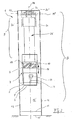
- Fig. 2
- eine Vorderansicht der Vorrichtung gemäß
Fig. 1 , - Fig. 3
- eine Draufsicht der Vorrichtung gemäß
Fig. 2 , - Fig. 4
- eine Seitenansicht ähnlich
Fig. 1 mit einer zweiten Ausführung der Vorrichtung mit konstruktiv geändertem Aufnahmeteil, - Fig. 5
- eine vergrößerte Ausschnittsdarstellung im Verbindungsbereich eines einen Vorratsbehälter aufnehmenden Aufnahmeteils unterhalb eines Preßkolbens,
- Fig. 6
- eine Einzeldarstellung des Aufnahmeteils mit dem Verbinder nach Art eines Bajonett-Verschlusses an einer Tragplatte des Gehäuseteils,
- Fig. 7
- eine Einzeldarstellung des Aufnahmeteils mit oberseitigem Profilansatz,
- Fig. 8
- eine Draufsicht des Aufnahmeteils gemäß
Fig. 7 , - Fig. 9
- eine Einzeldarstellung der Tragplatte gemäß einer Linie VI-VI in
Fig. 10 , und - Fig. 10
- eine Draufsicht der Tragplatte gemäß
Fig. 9 . - In
Fig. 1 ist eine insgesamt mit 1 bezeichnete Vorrichtung zum Ausgeben von Speiseeis dargestellt. Derartige Vorrichtungen 1 sind (ähnlichDE 28 13 349 ) mit einem topfförmigen Vorratsbehälter 2 zu bestücken, in dem eine nicht näher dargestellte Eisportion eingefüllt ist. In der dargestellten Bedienstellung wird der Vorratsbehälter 2 im Nahbereich eines verlagerbaren Preßkolbens 3 abgestützt. Danach wird der einen Stellantrieb 5 aufweisende Preßkolben 3 in einer Hubrichtung gemäß Pfeil H verlagert, dabei das im Vorratsbehälter 2 befindliche Speiseeis durch jeweilige Öffnungen 6 im Behälterboden 7 gepreßt und danach kann das Speiseeis in Form von Spaghetti-Eis in einem nicht dargestellten Servierbehälter aufgenommen werden. - Die Vorrichtung 1 ist erfindungsgemäß als eine Baueinheit B ausgebildet, die im Bereich des Preßkolbens 3 einen mit einem Elektrozylinder 25 (
Fig. 1 ) versehenen Stellantrieb 5 aufweist. Diese nur einen Elektroanschluß E erfordernde Baueinheit B weist ein verbessertes und im wesentlichen geschlossenes Gehäuseteil 9 auf, in das sämtliche der Bauteile optimal integriert sind. Damit ist die Baueinheit B an weitgehend beliebigen Anwendungsorten mit lediglich einem Elektroanschluß E betreibbar und zusätzliche Kompressoren mit Steuerleitungen u. dgl. Zusatzteilen außerhalb des Gehäuses 9 sind entbehrlich. - Durch eine Kombination des aus Edelstahlblech bestehenden Gehäuseteils 9 mit dem als Standardbaugruppe einsetzbaren Elektrozylinder 25 wird die Baueinheit B sowohl den Forderungen nach niedrigen Gestehungskosten als auch steigenden Hygieneanforderungen gerecht. Der Standard-Elektrozylinder 25 weist in geschlossener Bauform einen Elektromotor 8, ein Getriebe 26 und einen mit dem Preßkolben 3 verbindbaren Hubteil K auf, wobei diese Baugruppe durch umgebende Wandungen (
Fig. 5 ) zum Innenraum G des Gehäuses 9 hin keine Verbindung aufweist. - Das Konzept der kompakten Baueinheit B ist darauf abgestellt, daß im Bereich des Stellantriebes 5, des verlagerbaren Preßkolbens 3 und eines den Vorratsbehälter 2 beim Pressen des Eises abstützenden Aufnahmeteils 4 jeweilige lösbare Verbindungen als Halterung vorgesehen sind. Damit ist im Bedarfsfall eine schnelle Demontage funktionswesentlicher Teile möglich und diese können einfach gesäubert werden. Im Bereich von Preßkolben 3 und Hubteil K ist diese lösbare Verbindung insbesondere durch eine Schraubverbindung 10 erreicht. Auch der Aufnahmeteil 4 kann durch eine Schraubverbindung 11 mit dem Gehäuse 9 so verbunden werden, daß eine einfache Trennung in diesem Funktionsbereich möglich ist, gleichwohl ein ungewolltes Eintreten von Speiseeis o. dgl. in den Gehäuseinnenraum G verhindert ist.
- Es versteht sich, daß in zweckmäßiger Ausführung diese zur Verarbeitung von Lebensmitteln vorgesehene Vorrichtung 1 im Bereich des Gehäuses 9 jeweilige aus Edelstahlblech gefertigte seitliche Wandteile 12, 13, einen entsprechenden Deckelteil 14 sowie einen Bodenteil 15 aufweist. Diese Edelstahlteile bilden eine insgesamt kompakte Einheit, wobei denkbar ist, durch mehrmalige Abkantungen eines Blechhalbzeuges im wesentlichen einstückige Wandungsteile hoher Eigenstabilität zu bilden. Gleichzeitig ist diese materialsparende Konstruktion so ausgelegt, daß durch die Halterung der Wandteile zueinander, die Einbaulage des Stellantriebes 5 (
Fig. 1 ,Fig. 4 ) und/oder Zwischenwände 37", 39 (Fig. 5 ) die gesamte Baueinheit B stabil ist. - Das Bodenteil 15 ist in Form einer Tropfschale 16 (
Fig. 4 ) so ausgebildet, daß die in Gebrauchsstellung über dieser Tropfschale 16 befindlichen Bauteile für die Pressung des Spaghetti-Eises vollständig untergriffen sind und damit ein ungewollter Austritt von Speiseeisresten an die Umgebung verhindert wird. - Zur Festlegung des Preßkolbens 3 bzw. der Stellantrieb-Baugruppe 5 am Gehäuse 9 ist am Deckelteil 14 eine Halterung 17 (
Fig. 3 ) vorgesehen, die an den Wandungsteilen 12, 13 und einer Rückwand 18 gehaltene Stützschenkel 19, 20 aufweist. Zwischen diesen Stützschenkeln 19, 20 erstrecken sich vorzugsweise zwei Querträger 21, 21', an denen der eine vertikale Hochachse M definierende Stellantrieb 5 festgelegt ist. Dargestellt ist ein Tragauge 22 für den als Antriebszylinder vorgesehenen Elektrozylinder 25, der an einem Haltebolzen 22' gehalten ist. Dieser weist seinerseits jeweilige endseitige Spannschrauben 23, 23' zur Halterung an jeweiligen Längsstegen 24, 24' auf. Damit ist erreichbar, daß der Stellantrieb 5 im Bereich der Querachse M' auch pendelnd aufhängbar ist. - In einer zweiten Ausführung der Halterung 17' (
Fig. 5 ) ist vorgesehen, daß der Elektrozylinder 25 durch jeweilige Verbindungsschrauben 19', 20' o. dgl. Elemente mit der Tragplatte 37' verbunden ist. Damit kann eine lösbare Fixierung erreicht werden, wobei die obere Halterung 17 (Fig. 1 ) entbehrlich sein kann. - Die Zusammenschau von
Fig. 1 und3 verdeutlicht, daß in das auch in Bereichen 18', 18" einer Vorderwand-Platte weitgehend geschlossene Gehäuseteil 9 sowohl der mit dem Elektromotor 8 verbundene Elektrozylinder 25 des Preßkolbens 3 als auch ein den Elektromotor 8 mit dem Elektrozylinder 25 verbindendes Getriebeteil 26 und ein Steuertrafo 27 sowie ein Lüfter 28 integriert sind. Bei optimaler Größe des als Hüllform wirksamen Gehäuseteils 9 ist damit eine kompakte Einheit geschaffen. Im Bereich des Preßkolbens 3 ist zwischen den Teilen 18" und 18''' der Vorderwand zusätzlich eine horizontale Tragplatte 37 vorgesehen, die den Elektrozylinder 25 durch ein Stabilisierungsblech 38 aufnimmt und damit diesen Bereich zusätzlich abdeckt. - Für eine weitgehend automatische Handhabung dieser Baueinheit B weist der Preßkolben 3 im Bereich des Elektrozylinders 25 jeweilige zur Steuerung des Hubweges (Pfeil H) vorgesehene Endlagensensoren 29 und 30 auf, die serienmäßig an dieser Baugruppe angebaut sind. Diese als an sich bekannte Serien-Bauteile bereitstellbaren Elemente des Stellantriebes 5 können bei der erfindungsgemäßen Vorrichtung 1 optimal in das Edelstahl-Gehäuse 9 integriert werden, so daß bei geringem Raumbedarf eine besonders geräuscharme Funktion der Baueinheit B erreicht wird. An Stelle der Endlagensensoren ist auch ein Wegmeßsystem o. dgl. Positionskennung denkbar.
- Im Bereich des den Vorratsbehälter 2 umfassenden Aufnahmeteils 4 ist ein zusätzlicher Signalgeber 31 vorgesehen, der in zweckmäßiger Ausführung mit dem Stellantrieb 5 bzw. dem Elektromotor 8 des Preßkolbens 3 zusammenwirkt. Während einer Positionierung des Vorratsbehälters 2 durch eine Bedienperson, die den Vorratsbehälter entsprechend einer an sich bekannten Aufnahmenut 32 mittels eines Handhebels 33 in eine Raststellung am Aufnahmeteil 4 verlagert, wird auch der Signalgeber 31 betätigt. Danach erfolgt die Absenkbewegung gemäß Pfeil H automatisch, wobei der Preßkolben 3 entsprechend den Endlagensensoren 29 und 30 gesteuert und aus einer oberen Lage abgesenkt bzw. in diese zurückbewegt wird.
- In vorteilhafter Ausführung ist als Signalgeber im Bereich des Aufnahmeteils 4 ein Näherungsschalter 34 vorgesehen, der mit dem Haltestift 35 des Vorratsbehälters 2 aktiviert wird. Insbesondere erfolgt eine berührungslose Aktivierung des Schalters 34. Dieser ist so im Wandbereich 18" positioniert, daß eine weitgehend spaltfreie Oberfläche zum vorgelagerten Funktionsbereich hin besteht.
- Mit dem erfindungsgemäßen Antrieb über den Elektro-Hubzylinder 25 kann der Preßkolben 3 mit weitgehend variablen Preßgeschwindigkeiten bewegt werden, da im Bereich des Elektromotors 8 bzw. des Getriebes 26 eine schnelle Anpassung an unterschiedliche Geschwindigkeiten möglich ist. Insbesondere ist die Bewegung des Preßkolbens 3 auch stufenlos regelbar.
- Das eine geschlossene Baueinheit bildende Gehäuseteil 9 ist im Bereich zumindest einer ihrer Wandungen mit jeweiligen Lüftungsöffnungen 36 (
Fig. 3 ) versehen, wobei diese Öffnungen auch im Bereich der Rückwand 18 bzw. der Seitenwände 12 oder 13 vorgesehen sein können. - Die erfindungsgemäße Baueinheit B ist mit ihrem raumsparenden und leichtbauenden Konzept einfach transportabel, wobei mit den durch Abkantung des Edelstahlbleches geformten Wandteilen 12, 13, 14, 15, 18 ein weitgehend einstückiger Gehäuseteil 9 gebildet werden kann, der auch eine optisch ansprechende Gestaltung aufweist.
- In
Fig. 4 ist eine insgesamt mit 1' bezeichnete Vorrichtung zum Ausgeben von Speiseeis in einer zweiten Ausführung dargestellt. Auch das Konzept der kompakten Baueinheit B gemäßFig. 4 ist darauf abgestellt, daß im Bereich des Stellantriebes 5, des verlagerbaren Preßkolbens 3 und des den Vorratsbehälter 2 beim Pressen des Eises abstützenden Aufnahmeteils 4 jeweilige lösbare Verbindungen als Halterung vorgesehen sind. - Der Stellantrieb 5 kann im Bereich seines mit dem Getriebe 26 und dem Motor 8 verbundenen Elektrozylinders 25 vorteilhaft mit einer nicht näher dargestellten Kugel-Rollen-Spindel als das Hubteil K versehen sein. An deren Stelle ist auch ein pneumatischer oder hydraulischer Antrieb denkbar. Im Bereich eines Steuerteils 56 ist eine Bedienung des Stellantriebs 5 möglich, womit durch entsprechende Geschwindigkeits-Einstellungen der Preßbewegung des Kolbens 3 (Pfeil H) eine Anpassung an variierende Konsistenzen des im Vorratsbehälter 2 befindlichen Eises erreicht wird.
- In
Fig. 5 bis 10 zeigen jeweilige vergrößerte Darstellungen einen speziellen Aufbau der Bauteil-Verbindung 11', wobei diese prinzipiell als Schraub- und/oder Klemmverbindung vorgesehen sein kann. Neben einer direkten Verbindung des Aufnahmeteils 4 mit dem Gehäuseteil 9 durch ein Gewinde ist denkbar, das Aufnahmeteil 4 im Bereich einer Tragplatte 37' - die ihrerseits zwischen zwei Wandteilen 39, 40 des Gehäuses 9 gehalten ist - durch eine nicht näher dargestellte Steckverbindung aufzunehmen. Mittels einer quer zur Längsmittelebene M wirkenden Schraube 41 o. dgl. Klemmteil(e) (Pfeil A,Fig. 5 ) ist eine Fixierung möglich. Der obere Randbereich des Aufnahmeteils 4 kann dabei mittels der Klemmschraube 41 bei R erfaßt und in Spannrichtung A gegen ein im Bereich des Wandteils 39 befindliches Anlageelement 52 gedrückt werden. - Die Detaildarstellungen gemäß
Fig. 6 bis 10 verdeutlichen, daß das Aufnahmeteil 4 am in Einbaulage oberen Ende einen Profilansatz P (Fig. 6 ) aufweist, der mit einem gehäuseseitigen bzw. im Bereich der Tragplatte 37' vorgesehenen Gegenprofil 42 (Fig. 10 ) verbindbar ist. - In zweckmäßiger Ausführung ist diese in
Fig. 6 dargestellte Profil-Verbindung nach Art eines Bajonett-Verschlusses ausgebildet, so daß das Aufnahmeteil 4 in einer vertikalen Verbindungsrichtung (Pfeil B',Fig. 6 ) in die komplementär profilierte Durchlaßöffnung 43 der Tragplatte 37' verlagerbar und durch eine entsprechende Schwenkbewegung (Pfeil D,Fig. 6 ) im Bereich von Profilansatz P und Gegenprofil 42 ver- bzw. entriegelbar ist. - In zweckmäßiger Ausführung ist das Aufnahmeteil 4 mit einem den Profilansatz P aufweisenden Ringteil 46 (
Fig. 8 ) versehen, das oberseitig mit dem Aufnahmeteil 4 verschweißt ist. Das Gegenprofil 42 ist in der als eine Aufnahmeplatte wirksamen Tragplatte 37' bzw. im Randbereich deren Öffnung 43 so geformt, daß vier Aufnahmeöffnungen 44 bzw. Ansatzteile 45 vorgesehen sind. Diese nach Art eines Bajonett-Verschlusses wirksame Profilierung ist mit den entsprechenden Profilen 44' und 45' des Aufnahmeteils 4 (Fig. 8 ) verrastbar und insbesondere zu Reinigungszwecken einfach entriegelbar. - Als Sicherung kann zwischen der Tragplatte 37' und dem Profilansatz P des Aufnahmeteils 4 eine zusätzliche Klemmschraube 41' (
Fig. 10 ) vorgesehen sein, deren Drehbewegung eine Klemmwirkung in Pfeilrichtung C bewirkt (ähnlich der Klemmschraube 41 inFig. 4 ) und damit das Aufnahmeteil 4 an der Tragplatte 37' fixiert. - Im Bereich der Verbindung 11' (
Fig. 5 ) ist eine zusätzliche Stützplatte 37" vorgesehen sein, so daß dieser beim Bedienen der Vorrichtung 1' belastete Teilbereich zusätzlich ausgesteift ist. Die Stützplatte 37" erstreckt sich dabei zwischen den Wandteilen 39 und 40 des Gehäuses 9 und weist eine unterhalb des Stellantriebs 5 vorgesehene Durchlaßöffnung 55 auf, die mit einer nicht näher dargestellten Dichtung so verschlossen ist, daß der Innenraum G des Gehäuses 9 vom funktionalen Eis-Füllbereich F getrennt ist und ungewollte Verschmutzungen des System-Innenraums vermieden sind. - Die am Gehäuse 9 gehaltene Stützplatte 37" ist vorteilhaft so dimensioniert, daß an dieser die Stützplatte 37' mittels deren Halteöffnungen 53 (
Fig. 10 ) durchgreifender Schrauben (nicht dargestellt) o. dgl. Verbindungsmittel im Bereich S (Fig. 6 ) festlegbar ist. - Der Vorratsbehälter 2 (
Fig. 4 ) weist einen Handgriff 48 auf, dessen Tragarm 49 in eine im Aufnahmeteil 4 vorgesehene Aufnahmenut 50 vertikal einführbar und zu einem quer verlaufenden Nutschenkel 51 hin radial verlagerbar ist. In dieser Position ist beim Pressen von Eis (Preßkolbenbewegung gemäß Pfeil H,Fig. 4 ) eine stabile Verbindung von Vorratsbehälter 2 und Aufnahmeteil 4 erreicht und die berührungslose Kontaktgabe zwischen Haltestift 35 und Näherungsschalter 34 gewährleistet (Fig. 5 ). - Die vorbeschriebene Vorrichtung 1' ist so konzipiert, daß durch eine einfache Demontage eine komplette Trennung der Eis-Ausgabeteile von der als Basisstation bereitgestellten Bedienbaugruppe 13 (
Fig. 2 ) möglich ist. Damit können die von den Bedingungen der Lebensmittelhygiene vorgesehenen Anforderungen sicher erfüllt werden. Zu Reinigungszwecken kann das Aufnahmeteil 4 im Verbindungsbereich bei 11' vom Gehäuse 9 getrennt werden, der Preßkolben 3 ist im Bereich T (Fig. 5 ) vom Stellantrieb 5 lösbar und die bodenseitige Tropfschale 16 kann ebenfalls einfach gesäubert werden. - Der das Eis aufnehmende Vorratsbehälter 2 (
Fig. 4 ) weist im Bereich seines Behälterbodens 7 ebenfalls lösbare Verbindungen auf, wobei ein der gewünschten Eis-Formung anpaßbares Einlegeblech 57 (mit den Öffnungen 6) durch einen Schraubring 58 so gehalten ist, daß auch hier eine schnelle Demontage und Reinigung möglich ist. Sämtliche Einzelteile können einer Spülmaschine o. dgl. zugeführt werden und nach der Reinigung ist eine einfache Montage der Baueinheit B im Ausgabebereich F möglich.
Claims (22)
- Vorrichtung zum Ausgeben von Speiseeis, insbesondere in Form von Spaghetti-Eis, die mit einem in einem topfförmigen Vorratsbehälter (2) verlagerbaren Preßkolben (3) versehen ist, derart, daß mit dem einen elektromotorischen Stellantrieb (5) aufweisenden Preßkolben (3) das in dem am Gehäuseteil (9) gehaltenen Vorratsbehälter (2) befindliche Speiseeis durch jeweilige Öffnungen (6) im Behälterboden (7) auspreßbar und einem unter diesem befindlichen Servierbehälter übergebbar ist, dadurch gekennzeichnet, daß als Stellantrieb (5) eine Standardbaugruppe in Form eines einen Elektromotor (8), einen Getriebeteil (26) und einen mit dem Preßkolben (3) verbindbaren Hubteil (K) aufweisenden Elektrozylinders (25) vorgesehen ist und dieser in einem nur Edelstahlbleche als Wandungsteile (12, 13, 18) aufweisenden Gehäuseteil (9) abgestützt ist, derart, daß dessen außenliegender Funktionsbereich (F) zumindest nahe dem Preßkolben (3) weitgehend spaltfrei geformt und damit eine hygienesichere Baueinheit (B) gebildet ist.
- Vorrichtung nach Anspruch 1, dadurch gekennzeichnet, daß die Baueinheit (B) zumindest im Bereich des Stellantriebes (5), des verlagerbaren Preßkolbens (3), des Vorratsbehälters (2) und eines diesen beim Pressen des Eises abstützenden Aufnahmeteils (4) eine jeweilige demontierbare Baugruppe bildet.
- Vorrichtung nach Anspruch 1 oder 2, dadurch gekennzeichnet, daß die Funktions- und Stützteile der Baueinheit (B) so in die Wandteile (12, 13, 18, 18') integriert sind, daß eine weitgehend geschlossene und in sich stabile Hüllkontur gebildet ist.
- Vorrichtung nach einem der Ansprüche 1 bis 3, dadurch gekennzeichnet, daß das Gehäuseteil (9) der Baueinheit (B) einen diese auf einer Unterlage abstützenden Bodenteil (15) in Form einer Tropfschale (16) aus Edelstahlblech aufweist.
- Vorrichtung nach einem der Ansprüche 1 bis 4, dadurch gekennzeichnet, daß der Stellantrieb (5) mit dem Elektrozylinder (25) einerseits an einem oberen Deckelteil (14) des Gehäuses (9) gehalten und andererseits ein die Wandung (37) durchgreifender Hubteil (K) mit dem Preßkolben (3) verbindbar ist.
- Vorrichtung nach Anspruch 5, dadurch gekennzeichnet, daß der Stellantrieb (5) mittels einer lösbaren Halterung (17) am Deckelteil (14) fixierbar ist.
- Vorrichtung nach einem der Ansprüche 1 bis 6, dadurch gekennzeichnet, daß der mit dem Elektromotor (8) sowie dem Getriebeteil (26) verbundene Elektrozylinder (25), ein Lüfter (28) und ein Steuertrafo (27) in das weitgehend geschlossene Gehäuseteil (9) integrierbar sind.
- Vorrichtung nach einem der Ansprüche 1 bis 7, dadurch gekennzeichnet, daß das mit dem Vorratsbehälter (2) verbindbare Aufnahmeteil (4) als eine Aufnahmehülse ausgebildet ist, die einerseits im Bereich des Preßkolbens (3) lösbar mit dem Gehäuse (9) verbunden ist und andererseits eine den Vorratsbehälter (2) lösbar erfassende Verbindungskontur aufweist.
- Vorrichtung nach einem der Ansprüche 1 bis 8, dadurch gekennzeichnet, daß im Bereich des Elektrozylinders (25) jeweilige zur Steuerung des Hubweges (H) wirksame Endlagensensoren (29, 30) vorgesehen sind und in deren Nahbereich das Gehäuse (9) jeweilige dieses stabilisierende Wandteile (18", 38) aufweist.
- Vorrichtung nach einem der Ansprüche 1 bis 9, dadurch gekennzeichnet, daß im Bereich des den Vorratsbehälter (2) mit rohrförmiger Kontur umfassenden Aufnahmeteils (4) ein mit dem Stellantrieb (5) des Preßkolbens (3) zusammenwirkender und dessen jeweilige Verlagerung (H) auslösender Signalgeber (31) vorgesehen ist, derart, daß mittels eines den Vorratsbehälter (2) im Aufnahmeteil (4) fixierenden Haltestiftes (35) eine berührungslose Signalauslösung durchführbar ist.
- Vorrichtung nach Anspruch 10, dadurch gekennzeichnet, daß als Signalgeber (31) ein Näherungsschalter (34) vorgesehen ist.
- Vorrichtung nach einem der Ansprüche 1 bis 11, dadurch gekennzeichnet, daß dem Preßkolben (3) mittels des stufenlos regelbaren Stellantriebes (5) unterschiedliche Preßgeschwindigkeiten vorgebbar sind.
- Vorrichtung nach einem der Ansprüche 1 bis 12, dadurch gekennzeichnet, daß die Wandungen (12, 13, 14) des Gehäuseteils (9) zumindest bereichsweise mit Lüftungsöffnungen (36) versehen sind.
- Vorrichtung nach einem der Ansprüche 1 bis 13, dadurch gekennzeichnet, daß mit den durch Abkantung von Edelstahlblech-Teilen geformten Wandteilen (12, 13, 18; 18', 18", 18"') ein im wesentlichen einstückiges Gehäuseteil (9) gebildet und dieses zumindest im Funktionsbereich des Preßkolbens (3) weitgehend spaltfrei ist.
- Vorrichtung nach einem der Ansprüche 1 bis 14, dadurch gekennzeichnet, daß das hülsenförmige Aufnahmeteil (4) am Gehäuseteil (9) mittels einer Schraub- und/oder Klemmverbindung (11') festlegbar ist.
- Vorrichtung nach Anspruch 15, dadurch gekennzeichnet, daß das Aufnahmeteil (4) mittels der Schraubverbindung direkt am Gehäuseteil (9) gehalten ist.
- Vorrichtung nach Anspruch 15, dadurch gekennzeichnet, daß das Aufnahmeteil (4) mittels einer dieses am oberen Ende erfassenden Klemmschraube (41) zwischen zwei Wandteilen (39, 40) des Gehäuses (9) gehalten ist.
- Vorrichtung nach einem der Ansprüche 15 bis 17, dadurch gekennzeichnet, daß das Aufnahmeteil (4) am oberen Ende einen Profilansatz (P) aufweist, der mit einem gehäuseseitig gehaltenen Gegenprofil (42) verbindbar ist.
- Vorrichtung nach Anspruch 18, dadurch gekennzeichnet, daß die Verbindung (11') nach Art eines Bajonett-Verschlusses ineinandergreifende und durch eine Schwenkbewegung (Pfeil D) verrastbare Profile aufweist.
- Vorrichtung nach Anspruch 18 oder 19, dadurch gekennzeichnet, daß das Aufnahmeteil (4) mit einem ringförmigen Profilansatz (46) verschweißt ist und das Gegenprofil (42) als eine Tragplatte (37') mit profilierter Durchlaßöffnung (43) ausgebildet ist.
- Vorrichtung nach Anspruch 20, dadurch gekennzeichnet, daß die mit dem Aufnahmeteil (4) verbindbare Tragplatte (37) ihrerseits an einer gehäuseseitig gehaltenen Tragplatte (37") festlegbar ist.
- Vorrichtung nach einem der Ansprüche 18 bis 21, dadurch gekennzeichnet, daß das in die Tragplatte (37') eingerastete Aufnahmeteil (4) durch eine zusätzliche Klemmschraube (41') gesichert ist.
Priority Applications (1)
| Application Number | Priority Date | Filing Date | Title |
|---|---|---|---|
| PL07724472T PL2010002T3 (pl) | 2006-04-25 | 2007-04-23 | Urządzenie do wydawania lodów |
Applications Claiming Priority (3)
| Application Number | Priority Date | Filing Date | Title |
|---|---|---|---|
| DE200610019626 DE102006019626A1 (de) | 2006-04-25 | 2006-04-25 | Vorrichtung zum Ausgeben von Speiseeis |
| DE200620008741 DE202006008741U1 (de) | 2006-05-31 | 2006-05-31 | Vorrichtung zum Ausgeben von Speiseeis |
| PCT/EP2007/003542 WO2007121967A2 (de) | 2006-04-25 | 2007-04-23 | Vorrichtung zum ausgeben von speiseeis |
Publications (2)
| Publication Number | Publication Date |
|---|---|
| EP2010002A2 EP2010002A2 (de) | 2009-01-07 |
| EP2010002B1 true EP2010002B1 (de) | 2009-09-23 |
Family
ID=38440199
Family Applications (1)
| Application Number | Title | Priority Date | Filing Date |
|---|---|---|---|
| EP07724472A Not-in-force EP2010002B1 (de) | 2006-04-25 | 2007-04-23 | Vorrichtung zum ausgeben von speiseeis |
Country Status (6)
| Country | Link |
|---|---|
| EP (1) | EP2010002B1 (de) |
| AT (1) | ATE443450T1 (de) |
| DE (1) | DE502007001591D1 (de) |
| DK (1) | DK2010002T3 (de) |
| PL (1) | PL2010002T3 (de) |
| WO (1) | WO2007121967A2 (de) |
Families Citing this family (6)
| Publication number | Priority date | Publication date | Assignee | Title |
|---|---|---|---|---|
| CN101401608B (zh) * | 2008-09-24 | 2011-03-09 | 宁波鑫盛达机械有限公司 | 冰淇淋制作上旋转装置 |
| GB0916618D0 (en) * | 2009-09-22 | 2009-11-04 | Mcgill Tech Ltd | Apparatus for dispensing food product |
| DE102019127504B3 (de) * | 2019-10-11 | 2021-04-01 | CryonCo GmbH & Co. KG | Vorrichtung zum Herstellen von Trockeneis |
| EP4014747A1 (de) * | 2020-12-17 | 2022-06-22 | Oliver Grohe | System und verfahren zur herstellung von spaghettieis und zugehörige spaghettieismaschine und eiskartusche |
| US20240292979A1 (en) | 2023-03-03 | 2024-09-05 | Sharkninja Operating Llc | Extrusion assembly for a micro-puree machine |
| US12207669B1 (en) | 2023-08-28 | 2025-01-28 | Sharkninja Operating Llc | Nozzle control assemblies for a micro-puree machine |
Family Cites Families (7)
| Publication number | Priority date | Publication date | Assignee | Title |
|---|---|---|---|---|
| DE7418128U (de) * | 1974-10-03 | Kasper W | Vorrichtung zur Herstellung und zur Abgabe von Speiseeis | |
| US3984033A (en) * | 1975-12-29 | 1976-10-05 | Wear-Ever Aluminum, Inc. | Electric gun for dispensing of comestibles |
| IT1209441B (it) * | 1977-03-29 | 1989-08-30 | B M Dei F Lli Bravo Genesio Fr | Macchina per la formazione di spaghetti di gelato. |
| EP0128258A1 (de) * | 1983-06-09 | 1984-12-19 | BOVO S.a.s. dei F.lli Pillon Claudio e Paolo & C. | Maschine für die Formgebung von Nahrungsmitteln |
| DE3542290A1 (de) * | 1985-11-29 | 1987-06-04 | Luigino Casagrande | Vorrichtung zum ausformen von plastisch verformbaren massen |
| IT211889Z2 (it) * | 1987-09-11 | 1989-05-25 | Bravo Spa | Macchina perfezionata per laproduzione di spaghetti di gelato. |
| US5820892A (en) * | 1996-09-27 | 1998-10-13 | Lauer; James D. | Food extrusion assembly |
-
2007
- 2007-04-23 DE DE502007001591T patent/DE502007001591D1/de active Active
- 2007-04-23 PL PL07724472T patent/PL2010002T3/pl unknown
- 2007-04-23 WO PCT/EP2007/003542 patent/WO2007121967A2/de not_active Ceased
- 2007-04-23 DK DK07724472T patent/DK2010002T3/da active
- 2007-04-23 EP EP07724472A patent/EP2010002B1/de not_active Not-in-force
- 2007-04-23 AT AT07724472T patent/ATE443450T1/de active
Also Published As
| Publication number | Publication date |
|---|---|
| WO2007121967A2 (de) | 2007-11-01 |
| DK2010002T3 (da) | 2009-12-21 |
| EP2010002A2 (de) | 2009-01-07 |
| DE502007001591D1 (de) | 2009-11-05 |
| WO2007121967A3 (de) | 2008-02-07 |
| ATE443450T1 (de) | 2009-10-15 |
| PL2010002T3 (pl) | 2010-02-26 |
Similar Documents
| Publication | Publication Date | Title |
|---|---|---|
| EP2010002B1 (de) | Vorrichtung zum ausgeben von speiseeis | |
| DE2736532C3 (de) | Automatische Sprühvorrichtung | |
| DE19907057A1 (de) | Dunstabzugsvorrichtung, angeordnet im Bereich neben offenen Garungsbereichen | |
| EP1774883B1 (de) | Kaffeemaschine | |
| EP1829656B1 (de) | Holzbearbeitungsmaschine | |
| EP3692306A1 (de) | Dunstabzugsvorrichtung | |
| DE3706351C3 (de) | Durch einen Druckluft-Kolbenmotor angetriebene Flüssigkeits-Kolbenpumpe | |
| DE102004023964B3 (de) | Kaffeemaschinenautomat | |
| EP2110482B1 (de) | Sanitäreinrichtung aufweisend eine Sanitärarmatur mit einem aus- und einfahrbaren Auslaufrohr | |
| DE2000395A1 (de) | Knet- und Mischmaschine fuer Fleisch- und Wurstwaren | |
| EP3048936B1 (de) | Vorrichtung zum zubereiten von speisen | |
| DE2439417B2 (de) | Aufbrühvorrichtung für warme Getränke | |
| DE3214818C2 (de) | Grillgerät mit einem eine darin angeordnete Tragscheibe aufweisenden Gehäuse | |
| EP2036467B1 (de) | Perkolator zur Zubereitung von Brühgetränken | |
| EP0598246B1 (de) | Zahntechnischer Arbeitsplatz mit einem Arbeitstisch und einer Absaugeinrichtung mit einem Filtergerät | |
| DE3706002A1 (de) | Vorrichtung zum zerkleinern, mischen, kneten und schlagen von gut | |
| WO2004018371A1 (de) | Pressstempelmechanismus einer glasformmaschine | |
| DE29512854U1 (de) | Drehmesser mit Absaugung für Fleisch oder Fett | |
| EP3788306B1 (de) | Verbindungselement | |
| DE202006019866U1 (de) | Vorrichtung zum Ausgeben von Speiseeis | |
| DE2845689C3 (de) | Schneidgerät zum Zerkleinern von Nahrungsmitteln, wie Fleisch, Zwiebel, Gemüse o.dgl. | |
| DE202006008741U1 (de) | Vorrichtung zum Ausgeben von Speiseeis | |
| DE3545226A1 (de) | Elektrisch betriebenes geraet fuer die bearbeitung und zubereitung von nahrungsmitteln aller art | |
| DE102006019626A1 (de) | Vorrichtung zum Ausgeben von Speiseeis | |
| DE2710300C2 (de) | Haushaltgerät, zum Zerkleinern von Lebensmitteln, insbesondere von Fleisch, Zwiebeln o.dgl. |
Legal Events
| Date | Code | Title | Description |
|---|---|---|---|
| PUAI | Public reference made under article 153(3) epc to a published international application that has entered the european phase |
Free format text: ORIGINAL CODE: 0009012 |
|
| 17P | Request for examination filed |
Effective date: 20081028 |
|
| AK | Designated contracting states |
Kind code of ref document: A2 Designated state(s): AT BE BG CH CY CZ DE DK EE ES FI FR GB GR HU IE IS IT LI LT LU LV MC MT NL PL PT RO SE SI SK TR |
|
| AX | Request for extension of the european patent |
Extension state: AL BA HR MK RS |
|
| GRAP | Despatch of communication of intention to grant a patent |
Free format text: ORIGINAL CODE: EPIDOSNIGR1 |
|
| DAX | Request for extension of the european patent (deleted) | ||
| GRAS | Grant fee paid |
Free format text: ORIGINAL CODE: EPIDOSNIGR3 |
|
| GRAA | (expected) grant |
Free format text: ORIGINAL CODE: 0009210 |
|
| AK | Designated contracting states |
Kind code of ref document: B1 Designated state(s): AT BE BG CH CY CZ DE DK EE ES FI FR GB GR HU IE IS IT LI LT LU LV MC MT NL PL PT RO SE SI SK TR |
|
| REG | Reference to a national code |
Ref country code: GB Ref legal event code: FG4D Free format text: NOT ENGLISH |
|
| REG | Reference to a national code |
Ref country code: CH Ref legal event code: EP Ref country code: CH Ref legal event code: NV Representative=s name: SCHNEIDER FELDMANN AG PATENT- UND MARKENANWAELTE |
|
| REG | Reference to a national code |
Ref country code: IE Ref legal event code: FG4D |
|
| REF | Corresponds to: |
Ref document number: 502007001591 Country of ref document: DE Date of ref document: 20091105 Kind code of ref document: P |
|
| REG | Reference to a national code |
Ref country code: DK Ref legal event code: T3 |
|
| REG | Reference to a national code |
Ref country code: SE Ref legal event code: TRGR |
|
| PG25 | Lapsed in a contracting state [announced via postgrant information from national office to epo] |
Ref country code: LT Free format text: LAPSE BECAUSE OF FAILURE TO SUBMIT A TRANSLATION OF THE DESCRIPTION OR TO PAY THE FEE WITHIN THE PRESCRIBED TIME-LIMIT Effective date: 20090923 Ref country code: FI Free format text: LAPSE BECAUSE OF FAILURE TO SUBMIT A TRANSLATION OF THE DESCRIPTION OR TO PAY THE FEE WITHIN THE PRESCRIBED TIME-LIMIT Effective date: 20090923 |
|
| LTIE | Lt: invalidation of european patent or patent extension |
Effective date: 20090923 |
|
| PG25 | Lapsed in a contracting state [announced via postgrant information from national office to epo] |
Ref country code: LV Free format text: LAPSE BECAUSE OF FAILURE TO SUBMIT A TRANSLATION OF THE DESCRIPTION OR TO PAY THE FEE WITHIN THE PRESCRIBED TIME-LIMIT Effective date: 20090923 Ref country code: SI Free format text: LAPSE BECAUSE OF FAILURE TO SUBMIT A TRANSLATION OF THE DESCRIPTION OR TO PAY THE FEE WITHIN THE PRESCRIBED TIME-LIMIT Effective date: 20090923 |
|
| REG | Reference to a national code |
Ref country code: PL Ref legal event code: T3 |
|
| PG25 | Lapsed in a contracting state [announced via postgrant information from national office to epo] |
Ref country code: CY Free format text: LAPSE BECAUSE OF FAILURE TO SUBMIT A TRANSLATION OF THE DESCRIPTION OR TO PAY THE FEE WITHIN THE PRESCRIBED TIME-LIMIT Effective date: 20090923 |
|
| REG | Reference to a national code |
Ref country code: IE Ref legal event code: FD4D |
|
| PG25 | Lapsed in a contracting state [announced via postgrant information from national office to epo] |
Ref country code: IS Free format text: LAPSE BECAUSE OF FAILURE TO SUBMIT A TRANSLATION OF THE DESCRIPTION OR TO PAY THE FEE WITHIN THE PRESCRIBED TIME-LIMIT Effective date: 20100123 Ref country code: PT Free format text: LAPSE BECAUSE OF FAILURE TO SUBMIT A TRANSLATION OF THE DESCRIPTION OR TO PAY THE FEE WITHIN THE PRESCRIBED TIME-LIMIT Effective date: 20100125 Ref country code: IE Free format text: LAPSE BECAUSE OF FAILURE TO SUBMIT A TRANSLATION OF THE DESCRIPTION OR TO PAY THE FEE WITHIN THE PRESCRIBED TIME-LIMIT Effective date: 20090923 Ref country code: RO Free format text: LAPSE BECAUSE OF FAILURE TO SUBMIT A TRANSLATION OF THE DESCRIPTION OR TO PAY THE FEE WITHIN THE PRESCRIBED TIME-LIMIT Effective date: 20090923 Ref country code: ES Free format text: LAPSE BECAUSE OF FAILURE TO SUBMIT A TRANSLATION OF THE DESCRIPTION OR TO PAY THE FEE WITHIN THE PRESCRIBED TIME-LIMIT Effective date: 20100103 Ref country code: EE Free format text: LAPSE BECAUSE OF FAILURE TO SUBMIT A TRANSLATION OF THE DESCRIPTION OR TO PAY THE FEE WITHIN THE PRESCRIBED TIME-LIMIT Effective date: 20090923 |
|
| PG25 | Lapsed in a contracting state [announced via postgrant information from national office to epo] |
Ref country code: SK Free format text: LAPSE BECAUSE OF FAILURE TO SUBMIT A TRANSLATION OF THE DESCRIPTION OR TO PAY THE FEE WITHIN THE PRESCRIBED TIME-LIMIT Effective date: 20090923 |
|
| PLBE | No opposition filed within time limit |
Free format text: ORIGINAL CODE: 0009261 |
|
| STAA | Information on the status of an ep patent application or granted ep patent |
Free format text: STATUS: NO OPPOSITION FILED WITHIN TIME LIMIT |
|
| 26N | No opposition filed |
Effective date: 20100624 |
|
| PG25 | Lapsed in a contracting state [announced via postgrant information from national office to epo] |
Ref country code: GR Free format text: LAPSE BECAUSE OF FAILURE TO SUBMIT A TRANSLATION OF THE DESCRIPTION OR TO PAY THE FEE WITHIN THE PRESCRIBED TIME-LIMIT Effective date: 20091224 |
|
| PG25 | Lapsed in a contracting state [announced via postgrant information from national office to epo] |
Ref country code: MC Free format text: LAPSE BECAUSE OF NON-PAYMENT OF DUE FEES Effective date: 20100430 |
|
| PG25 | Lapsed in a contracting state [announced via postgrant information from national office to epo] |
Ref country code: IT Free format text: LAPSE BECAUSE OF NON-PAYMENT OF DUE FEES Effective date: 20100423 |
|
| PG25 | Lapsed in a contracting state [announced via postgrant information from national office to epo] |
Ref country code: MT Free format text: LAPSE BECAUSE OF FAILURE TO SUBMIT A TRANSLATION OF THE DESCRIPTION OR TO PAY THE FEE WITHIN THE PRESCRIBED TIME-LIMIT Effective date: 20090923 |
|
| PG25 | Lapsed in a contracting state [announced via postgrant information from national office to epo] |
Ref country code: LU Free format text: LAPSE BECAUSE OF NON-PAYMENT OF DUE FEES Effective date: 20100423 Ref country code: HU Free format text: LAPSE BECAUSE OF FAILURE TO SUBMIT A TRANSLATION OF THE DESCRIPTION OR TO PAY THE FEE WITHIN THE PRESCRIBED TIME-LIMIT Effective date: 20100324 Ref country code: BG Free format text: LAPSE BECAUSE OF FAILURE TO SUBMIT A TRANSLATION OF THE DESCRIPTION OR TO PAY THE FEE WITHIN THE PRESCRIBED TIME-LIMIT Effective date: 20090923 |
|
| PG25 | Lapsed in a contracting state [announced via postgrant information from national office to epo] |
Ref country code: TR Free format text: LAPSE BECAUSE OF FAILURE TO SUBMIT A TRANSLATION OF THE DESCRIPTION OR TO PAY THE FEE WITHIN THE PRESCRIBED TIME-LIMIT Effective date: 20090923 |
|
| PGFP | Annual fee paid to national office [announced via postgrant information from national office to epo] |
Ref country code: CZ Payment date: 20140114 Year of fee payment: 8 |
|
| PGFP | Annual fee paid to national office [announced via postgrant information from national office to epo] |
Ref country code: GB Payment date: 20140422 Year of fee payment: 8 |
|
| PGFP | Annual fee paid to national office [announced via postgrant information from national office to epo] |
Ref country code: IT Payment date: 20140408 Year of fee payment: 8 Ref country code: FR Payment date: 20140428 Year of fee payment: 8 Ref country code: SE Payment date: 20140422 Year of fee payment: 8 Ref country code: AT Payment date: 20140425 Year of fee payment: 8 Ref country code: NL Payment date: 20140430 Year of fee payment: 8 |
|
| PGFP | Annual fee paid to national office [announced via postgrant information from national office to epo] |
Ref country code: PL Payment date: 20140311 Year of fee payment: 8 Ref country code: BE Payment date: 20140429 Year of fee payment: 8 Ref country code: DK Payment date: 20140415 Year of fee payment: 8 |
|
| PGFP | Annual fee paid to national office [announced via postgrant information from national office to epo] |
Ref country code: CH Payment date: 20140728 Year of fee payment: 8 |
|
| REG | Reference to a national code |
Ref country code: DK Ref legal event code: EBP Effective date: 20150430 |
|
| REG | Reference to a national code |
Ref country code: CH Ref legal event code: PL |
|
| REG | Reference to a national code |
Ref country code: SE Ref legal event code: EUG Ref country code: AT Ref legal event code: MM01 Ref document number: 443450 Country of ref document: AT Kind code of ref document: T Effective date: 20150423 |
|
| GBPC | Gb: european patent ceased through non-payment of renewal fee |
Effective date: 20150423 |
|
| REG | Reference to a national code |
Ref country code: NL Ref legal event code: MM Effective date: 20150501 |
|
| PG25 | Lapsed in a contracting state [announced via postgrant information from national office to epo] |
Ref country code: CH Free format text: LAPSE BECAUSE OF NON-PAYMENT OF DUE FEES Effective date: 20150430 Ref country code: GB Free format text: LAPSE BECAUSE OF NON-PAYMENT OF DUE FEES Effective date: 20150423 Ref country code: LI Free format text: LAPSE BECAUSE OF NON-PAYMENT OF DUE FEES Effective date: 20150430 Ref country code: IT Free format text: LAPSE BECAUSE OF NON-PAYMENT OF DUE FEES Effective date: 20150423 |
|
| REG | Reference to a national code |
Ref country code: FR Ref legal event code: ST Effective date: 20151231 |
|
| PG25 | Lapsed in a contracting state [announced via postgrant information from national office to epo] |
Ref country code: AT Free format text: LAPSE BECAUSE OF NON-PAYMENT OF DUE FEES Effective date: 20150423 Ref country code: CZ Free format text: LAPSE BECAUSE OF NON-PAYMENT OF DUE FEES Effective date: 20150423 Ref country code: FR Free format text: LAPSE BECAUSE OF NON-PAYMENT OF DUE FEES Effective date: 20150430 Ref country code: SE Free format text: LAPSE BECAUSE OF NON-PAYMENT OF DUE FEES Effective date: 20150424 |
|
| PG25 | Lapsed in a contracting state [announced via postgrant information from national office to epo] |
Ref country code: NL Free format text: LAPSE BECAUSE OF NON-PAYMENT OF DUE FEES Effective date: 20150501 |
|
| PG25 | Lapsed in a contracting state [announced via postgrant information from national office to epo] |
Ref country code: DK Free format text: LAPSE BECAUSE OF NON-PAYMENT OF DUE FEES Effective date: 20150430 |
|
| PG25 | Lapsed in a contracting state [announced via postgrant information from national office to epo] |
Ref country code: PL Free format text: LAPSE BECAUSE OF NON-PAYMENT OF DUE FEES Effective date: 20150423 |
|
| PG25 | Lapsed in a contracting state [announced via postgrant information from national office to epo] |
Ref country code: BE Free format text: LAPSE BECAUSE OF NON-PAYMENT OF DUE FEES Effective date: 20150430 |
|
| PGFP | Annual fee paid to national office [announced via postgrant information from national office to epo] |
Ref country code: DE Payment date: 20180115 Year of fee payment: 12 |
|
| REG | Reference to a national code |
Ref country code: DE Ref legal event code: R119 Ref document number: 502007001591 Country of ref document: DE |
|
| PG25 | Lapsed in a contracting state [announced via postgrant information from national office to epo] |
Ref country code: DE Free format text: LAPSE BECAUSE OF NON-PAYMENT OF DUE FEES Effective date: 20191101 |