EP2009590B1 - Drive assistance device - Google Patents
Drive assistance device Download PDFInfo
- Publication number
- EP2009590B1 EP2009590B1 EP07740457.2A EP07740457A EP2009590B1 EP 2009590 B1 EP2009590 B1 EP 2009590B1 EP 07740457 A EP07740457 A EP 07740457A EP 2009590 B1 EP2009590 B1 EP 2009590B1
- Authority
- EP
- European Patent Office
- Prior art keywords
- distortion correction
- image
- vehicle body
- level
- camera
- Prior art date
- Legal status (The legal status is an assumption and is not a legal conclusion. Google has not performed a legal analysis and makes no representation as to the accuracy of the status listed.)
- Active
Links
- 238000012937 correction Methods 0.000 claims description 179
- 238000003384 imaging method Methods 0.000 claims description 7
- 238000000034 method Methods 0.000 description 41
- 230000014509 gene expression Effects 0.000 description 24
- 230000003287 optical effect Effects 0.000 description 18
- 238000010586 diagram Methods 0.000 description 17
- 238000006243 chemical reaction Methods 0.000 description 14
- 238000009826 distribution Methods 0.000 description 11
- 230000000007 visual effect Effects 0.000 description 10
- 230000000694 effects Effects 0.000 description 9
- 238000012545 processing Methods 0.000 description 7
- 230000004044 response Effects 0.000 description 7
- 238000004364 calculation method Methods 0.000 description 5
- 230000006870 function Effects 0.000 description 5
- 238000012360 testing method Methods 0.000 description 5
- 230000004075 alteration Effects 0.000 description 4
- 238000013461 design Methods 0.000 description 3
- 230000006872 improvement Effects 0.000 description 3
- 238000012546 transfer Methods 0.000 description 3
- 230000008859 change Effects 0.000 description 2
- 230000002452 interceptive effect Effects 0.000 description 2
- 230000009467 reduction Effects 0.000 description 2
- 238000005452 bending Methods 0.000 description 1
- 238000004422 calculation algorithm Methods 0.000 description 1
- 239000003086 colorant Substances 0.000 description 1
- 238000004891 communication Methods 0.000 description 1
- 238000004590 computer program Methods 0.000 description 1
- 238000005520 cutting process Methods 0.000 description 1
- 239000006185 dispersion Substances 0.000 description 1
- 238000004519 manufacturing process Methods 0.000 description 1
- 238000003672 processing method Methods 0.000 description 1
- 238000012552 review Methods 0.000 description 1
- 238000010998 test method Methods 0.000 description 1
Images


Classifications
-
- G—PHYSICS
- G06—COMPUTING; CALCULATING OR COUNTING
- G06T—IMAGE DATA PROCESSING OR GENERATION, IN GENERAL
- G06T3/00—Geometric image transformations in the plane of the image
- G06T3/04—Context-preserving transformations, e.g. by using an importance map
- G06T3/047—Fisheye or wide-angle transformations
-
- G—PHYSICS
- G06—COMPUTING; CALCULATING OR COUNTING
- G06T—IMAGE DATA PROCESSING OR GENERATION, IN GENERAL
- G06T3/00—Geometric image transformations in the plane of the image
-
- G—PHYSICS
- G06—COMPUTING; CALCULATING OR COUNTING
- G06T—IMAGE DATA PROCESSING OR GENERATION, IN GENERAL
- G06T5/00—Image enhancement or restoration
- G06T5/80—Geometric correction
-
- H—ELECTRICITY
- H04—ELECTRIC COMMUNICATION TECHNIQUE
- H04N—PICTORIAL COMMUNICATION, e.g. TELEVISION
- H04N23/00—Cameras or camera modules comprising electronic image sensors; Control thereof
- H04N23/60—Control of cameras or camera modules
- H04N23/63—Control of cameras or camera modules by using electronic viewfinders
- H04N23/631—Graphical user interfaces [GUI] specially adapted for controlling image capture or setting capture parameters
-
- H—ELECTRICITY
- H04—ELECTRIC COMMUNICATION TECHNIQUE
- H04N—PICTORIAL COMMUNICATION, e.g. TELEVISION
- H04N25/00—Circuitry of solid-state image sensors [SSIS]; Control thereof
- H04N25/60—Noise processing, e.g. detecting, correcting, reducing or removing noise
- H04N25/61—Noise processing, e.g. detecting, correcting, reducing or removing noise the noise originating only from the lens unit, e.g. flare, shading, vignetting or "cos4"
-
- B—PERFORMING OPERATIONS; TRANSPORTING
- B60—VEHICLES IN GENERAL
- B60R—VEHICLES, VEHICLE FITTINGS, OR VEHICLE PARTS, NOT OTHERWISE PROVIDED FOR
- B60R2300/00—Details of viewing arrangements using cameras and displays, specially adapted for use in a vehicle
- B60R2300/30—Details of viewing arrangements using cameras and displays, specially adapted for use in a vehicle characterised by the type of image processing
-
- B—PERFORMING OPERATIONS; TRANSPORTING
- B60—VEHICLES IN GENERAL
- B60R—VEHICLES, VEHICLE FITTINGS, OR VEHICLE PARTS, NOT OTHERWISE PROVIDED FOR
- B60R2300/00—Details of viewing arrangements using cameras and displays, specially adapted for use in a vehicle
- B60R2300/40—Details of viewing arrangements using cameras and displays, specially adapted for use in a vehicle characterised by the details of the power supply or the coupling to vehicle components
- B60R2300/402—Image calibration
Definitions
- the present invention relates to a drive assistance device.
- a vehicle is increasingly generally equipped with a camera eliminating blind spots from the driver's position and improving visibility. It is said that the number of shipped cameras for visual recognition exceeds the two-million mark in 2006. The domestic sales number of new cars including trucks is a little less than six millions a year, and hence it follows that every third vehicle is mounted with a camera for visual recognition.
- Cameras for visual recognition include (1) a rear camera displaying an image at the rear of the vehicle when the vehicle is reversed, (2) a front -side camera displaying an image of the front wheel portion opposite to the driver, (3) a front camera for visually recognizing a blind spot immediately in front of the vehicle, and (4) a side-blind camera displaying an image of a side blind spot formed when the vehicle is started from a narrow alley or the like.
- the rear camera occupies 77 % of the cameras for visual recognition and forms the mainstream.
- a wide-angle optical system is generally employed in order to minimize the range of blind spots.
- the angle of a horizontal plane exceeds 100 degrees .
- Large "barrel" distortion aberration takes place in an image picked up by the onboard camera including such an optical system. Due to this distortion, it is hard for the driver to intuitively recognize the position of an obstacle appearing in the image and a feeling for the distance thereto.
- the first one is a method of suppressing distortion by devising the structure of the optical system
- the second one is a method of digitally correcting an image after picking up the image.
- Optical distortion correction is implemented by devising the structure of the optical system with an aspherical lens or the like, as described in Non-Patent Documents 1 and 2.
- Non-Patent Documents 3 and 4 As a technique of correcting lens distortion of a camera by image processing, the technique of Tsai (refer to Non-Patent Documents 3 and 4) and the algorithm proposed by Zhengyou Zhang (refer to Non-Patent Documents 5 and 6) are commonly employed. This technique is proposed also as a library packaged as a computer program (refer to Non-Patent Document 7), and can be utilized also for distortion correction in the present invention.
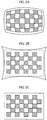
- a plurality of images obtained by shooting a regular known pattern present on a plane as shown in FIG. 1 while changing the relative relation between the camera and the plane are employed for calculating four parameters (k 1 , k 2 , p 1 and p 2 ) for performing distortion correction of the camera. These are parameters for controlling distortion correction level.
- the distortion correction level increases as the values of these parameters increase.
- the association between the coordinate positions (x', y') of an acquired image and the coordinate values (x, y) after distortion correction can be obtained through the following expressions (1).
- the coordinate positions are expressed in a coordinate system taking the x-coordinates in the horizontal direction and taking the y-coordinates in the vertical direction with the origin set at the center of the image.
- r 2 x 2 + y 2 .
- FIGS. 2A 2B and 2C are schematic diagrams showing examples of images obtained by performing distortion correction with the aforementioned technique.
- FIG. 2A shows an original image obtained by shooting the known pattern of FIG. 1
- FIG. 2B shows a distortion-corrected total image
- FIG. 2C shows a distortion-corrected cutout image.
- barrel distortion generally takes place as in the original image
- correction of the distortion results in an image such as the "distortion-corrected total image" having four stretching portions at the corners of the rectangle.
- conversion for expanding distorted portions is basically performed, and hence the size of the image is larger than that of the original image.
- the "distortion-corrected cutout image” obtained by cutting out a rectangular region (region surrounded by a rectangular frame of broken lines in FIG. 2B ) from the “distortion-corrected total image” is frequently employed for display, due to such a determination that these images are reduced in visibility.
- the internal rectangular region is cut out from the "distortion-corrected total image”
- the four portions at the corners of the image stretching in the distortion correction are discarded, and hence it follows that part of information having been acquired in the original image is not displayed. Therefore, the information content of the whole image is reduced, although the visibility of the observer may be improved.
- processing such as enlargement or reduction may accompany in response to the image resolution of the display system.
- a method of preparing a correction table (look-up table) previously associating addresses before and after correction and converting the addresses of pixels according to this look-up table is conceivable as means for performing distortion correction with hardware.
- Distortion has a two-dimensional shape and corrected pixel addresses do not necessarily correspond to uncorrected integral addresses, and hence a frame memory storing input images for one screen and an interpolation arithmetic circuit interpolating the pixels are required, to disadvantageously increase the circuit scale.
- Patent Document 1 proposes a technique of performing distortion correction with a line memory and an interpolation circuit for two pixels by performing the distortion correction with respect to the horizontal direction.
- Patent Document 2 proposes a technique of successively processing the X-axis and the Y-axis of an image in two stages, in order to simplify the structure of an interpolation circuit and avoid lacks on the four corners of the image resulting from distortion correction.
- the main object is simplification of the circuit, and there is no idea of controlling the level of distortion correction in order to improve observability of the user.
- Non-Patent Document 8 digital distortion correction
- the digital distortion correction it is possible to change the level of distortion and to improve the accuracy of the distortion correction by converting parameters for the distortion correction.
- the object is to uniformly reduce distortion point-symmetrically distributed about an optical axis.
- Non-Patent Document 8 " Digital Image Correcting Method for Digital Camera” , Ricoh Technical Report No. 31 (Dec. , 2005) http://www.ricoh.co.jp/about/business_overview/report/31/p df/A3114.pdf
- Patent Document 3 proposes distortion correction preserving a feeling for the distance by supplying loose distortion in the longitudinal and lateral directions on the assumption that complete correction of distortion is not necessarily advantageous for improvement of recognizability (particularly the feeling for the distance) of the driver.
- the principal object of this proposal is the improvement of the recognizability, and there is no idea of preserving the angle of view. Further, only loose conversion of distortion is described, and there is no concept of changing the level of distortion correction by dividing an image into regions.
- Patent Document 3 Japanese Unexamined Patent Publication No. 2003-123064 "Image Conversion Device and Image Pickup and/or Display Device provided with the Same"
- Patent Document 4 proposes a technique of extracting and enlargedly displaying a hitch portion in a vehicle having the hitch for pulling a trailer. This proposal proposes a technique of simultaneously displaying the hitch portion and a wide-range angle image as different images, and there is no concept of controlling the level of distortion correction.
- Patent Document 4 Japanese Patent No. 3483143 "Drive Assistance Device"
- Patent Document 5 proposes a technique of partially extracting an image of a noted region and simultaneously correcting distortion in a camera picking up an image at a wide angle of not less than 90 degrees. This proposal is equivalent to a technique of extracting an image after uniformly performing distortion correction, and there is no concept of controlling the level of distortion correction.
- Patent Document 5 Japanese Patent No. 3446277 "Ambient Situation Display for Vehicle"
- Patent Document 6 proposes a technique of optically supplying loose distortion correction by employing a prismatic optical member. Also in this proposal, only a technique of loosely changing distortion is described, and there is no concept of changing the level of distortion correction by dividing an image into regions. Further, the level of distortion correction cannot be changed after designing the optical system due to the optical distortion correction, and there is no concept of adjusting the correction level in response to the loaded state on the vehicle.
- Patent Document 6 Japanese Patent No. 3446991 "Monitor"
- Patent Document 7 proposes a technique of reducing the difference between appearances of regions close to and far from the vehicle respectively by virtually converting the mounting height of a rear camera of the vehicle and reducing a reflection of the bumper forming an unnecessary region in the visual field by virtually converting the mounting position of the camera in the anteroposterior direction.
- Patent Document 7 Japanese Patent No. 3624769 "Image Conversion Device for Rear Monitor for Vehicle"
- Non-Patent Document 9 employed as an option of a domestic automobile maker or Patent Document 8, the camera is virtually directed vertically downward, thereby recognizably displaying the positional relation between parking lines on a road and the user's vehicle.
- the principal objects of these proposals are improvement of recognizability, and the angle of view is sacrificed.
- Non-Patent Document 9 Suzuki Accessory for Every Wagon Select View Backeye Camera http://www.suzuki-accessory.jp/every/navi/99020_bl4.html
- Patent Document 8 Japanese Patent No. 3286306 "Image Forming Device, Image Forming Method"
- Patent Document 9 proposes a technique of comparing a reference test pattern set on a prescribed position in front of a vehicle and a determination pattern displayed on a prescribed position of a shot image in order to indicate whether or not the angle of a mounted camera is within a range allowing fine adjustment by image conversion or a method of adjusting the angle to the operator.
- This Patent pays attention to only angle adjustment of the camera, and there is no concept of adjusting a distortion coefficient.
- Patent Document 9 Japanese Patent No. 3565749 "Test Method for Image Pickup Direction of Onboard Camera and Test Device Thereof"
- Patent Document 10 proposes a technique of comparing a test pattern set on a prescribed position in front of a camera and an ideal image pickup position for the test pattern calculated from a reference position decided as a design value with respect to a vehicle with each other in order to correct the mounting position and the angle of the camera and deviation of a lens optical axis. While this Patent proposes calculation of camera parameters including a distortion coefficient from deviation between an actual image pickup position and the ideal image pickup position for the test pattern, there is no proposal for adjusting the distortion coefficient.
- Patent Document 10 Japanese Patent No. 3632563 "Image Positional Relation Correcting Device, Steering Assistance Device comprising the Image Positional Relation Correcting Device, and Image Positional Relation Correcting Method"
- US6211911B1 relates to mosaicing techniques for composing panoramic images from a plurality of overlapping smaller images, wherein distortion aberrations resulting from lens and parallax are corrected. Some image areas might not subjected to distortion correction at all.
- JP2002 140703A also relates to distortion correction varying over different regions. It describes a device for obtaining a more realistic perspective view from images provided by a wide-angle camera in a vehicle, wherein the image is divided by a horizontal segment into a constant domain, were no aberration correction is performed, and into a conversion area where perspective correction is performed by means of a function of the distance between a pixel to be corrected and a reference point.
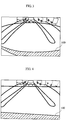
- the onboard camera generally has large lens distortion due to the employment of a wide-angle optical system. It is common to set a camera position so that the vehicle body is reflected in a part of an image as shown in FIG. 3 , so that obstacles close to the vehicle body and the user's vehicle can be grasped at the same time.
- a rear bumper (denoted by 100 in FIG. 3 ) is reflected as a part of the vehicle body. While the vehicle body must be partially reflected, it follows that the vehicle body occupies a large region of the image if lens distortion is remarkable.
- the mounting position of the camera is frequently offset from the center of the vehicle, and it is further difficult to detect the optimum camera position .
- FIG. 4 shows an image after distortion correction.
- the end of the vehicle body is hardly distorted, and such a disadvantage that the vehicle body is excessively largely reflected is dissolved.
- the diagonal information denotes information on regions on both sides of the upper visual field of the camera, and corresponds to information on the upper right and upper left portions in FIG. 3 .
- information of the vehicle on the upper right of FIG. 3 is lost, as shown by broken lines in FIG. 4 .
- the diagonal angle of view is important depends on the setting of the camera with respect to the vehicle body.
- the upper visual field of the camera picks up an image of the road surface if the camera has a large angle of depression.
- the road surface having a possibility of including obstacles such as persons and vehicles interfering with the user's vehicle, is an important region. It is unpreferable that the diagonal information is lost due to the distortion correction.
- the camera has a small angle of depression, the upper visual field of the camera is above the road surface. In this case, there is a small possibility that obstacles interfering with the user's vehicle are present, and the driver can directly visually recognize such obstacles in general. In the case of such camera setting, it is possible to apply distortion correction by attaching more importance to distortion than the diagonal information.
- An object of the present invention is to provide a drive assistance device capable of dividing an input image into a plurality of regions and varying distortion correction level with the regions when performing lens distortion correction on the input image.
- the drive assistance device includes an imaging device mounted on a vehicle body for imaging a region surrounding the vehicle body, lens distortion correction means for performing lens distortion correction on an input image picked up by the imaging device, and a display for displaying the image obtained by the lens distortion correction means, while the lens distortion correction means divides the input image into a plurality of regions, and performs lens distortion correction with distortion correction level varying with the regions.
- lens distortion correction means that dividing the input image into the plurality of regions in response to the distance from the vehicle body and/or the angle of depression of a camera and performing lens distortion correction with the distortion correction level varying with the regions may be employed, for example.
- Region setting means for setting the plurality of regions and distortion correction level decision means for deciding the distortion correction level every region set by the region setting means may be provided, and the aforementioned lens distortion correction means may perform lens distortion correction responsive to the distortion correction level decided by the distortion correction level decision means every region on the input image.
- Temporary region setting means for temporarily setting the plurality of regions, temporary distortion correction level decision means for temporarily deciding distortion correction level every region temporarily set by the temporary region setting means, means for displaying an effect of distortion correction responsive to the distortion correction level temporarily decided by the temporary distortion correction level decision means every region on the display with grid lines, and formal setting means for formally setting the distortion correction level temporarily decided by the temporary distortion correction level decision means every region as intrinsic distortion correction level every region may be provided, and the aforementioned lens distortion correction means may perform lens distortion correction responsive to the distortion correction level formally set by the formal setting means every region on the input image.
- an image region is divided into regions of a vehicle body portion, a portion close to the vehicle body and a distant portion, and lens distortion correction is performed with distortion correction level parameters previously set every region.
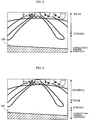
- FIG. 5 shows an example applying a strong level of lens distortion correction to the vehicle body portion and the portion around the vehicle body while applying lens distortion correction so that the level of correction is weakened as separated from the vehicle body in the distant portion.
- the strong level of lens distortion correction is applied to the vehicle body portion and the portion around the vehicle body, whereby the end of the vehicle body is correctly displayed in a straight line.
- the lens distortion correction is weak and hence the diagonal information content is preserved although lens distortion remains.
- the lens distortion correction shown in FIG. 5 is employed in a case where the diagonal information is not much important such that the camera has a small angle of depression.
- a strong level of lens distortion correction may be applied to the vehicle body portion, lens distortion correction may be applied so that the level of correction is weakened as separated from the vehicle body in the portion close to the vehicle body, and no lens distortion correction may be performed in the distant portion, as shown in FIG. 6 .
- the lens distortion correction shown in FIG. 6 is employed in a case where the diagonal information is important such that the camera has a large angle of depression.
- FIG. 7 shows the structure of a drive assistance device.
- the drive assistance device includes a camera 1 inputting an image, a lens distortion correction portion 2 and a monitor 3 displaying the image. While the lens distortion correction portion 2 is independent of the camera 1 or the monitor 3 in this example, the same may be integrated with the camera 1, or may be integrated with the monitor 3. In this example, a rear camera picking up a rear image of a vehicle is employed as the camera 1. In this Example, a calibration PC 50 is employed as a tool adjusting the level of lens distortion correction.
- the lens distortion correction portion 2 includes an LUT (look-up table) 21 storing association between the coordinates of an input image and an output image and a CPU 22 calculating a lens distortion corrected image on the basis of the LUT 21.
- the lens distortion correction portion 2 further includes an OSD (on-screen display) circuit 23 for recognizably displaying the distribution of distortion correction level (effect of lens distortion correction) on the image, as illustrated with reference to Example 2 described later.
- the CPU 22 is also in charge of a display instruction to the OSD circuit 23 and an interface with the PC 50.
- FIG. 8 shows the outline of the distortion correction technique with the LUT 21.
- the left side of FIG. 8 shows an input image (distorted image) 101
- the right side of FIG. 8 shows an output image (distortion-corrected image) 102.
- the origin (0, 0) is taken at the lower left of the input image, while x-coordinates are set on the axis of abscissas, and y-coordinates are set on the axis of ordinates.
- the origin (0, 0) is taken at the lower left of the output image, while i-coordinates are set on the axis of abscissas , and j -coordinates are set on the axis of ordinates.
- a pixel position P'(X i,j , Y i,j ) of an original image referred to for acquiring a pixel value on a certain pixel position P(i, j) of the output image 102 is held in the format of the look-up table.
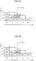
- FIGS. 9A and 9B show structural examples of the LUT 21.
- FIGS. 9A and 9B LUTS are held with respect to x-coordinates and y-coordinates respectively, with respect to each pixel position in the output image.
- FIG. 9A shows an LUT storing the x-coordinates of the input image corresponding to each pixel position (i, j) in the output image
- FIG. 9B shows an LUT storing the y-coordinates of the input image corresponding to each pixel position (i, j) in the output image.
- the pixel value of a pixel present on the position (0, 0) in the output image becomes the pixel value on a position (22.5, 43.7) of the input image.
- the pixel value of a pixel present on a position (2, 1) in the output image becomes the pixel value on a position (23.5, 44.2) of the input image.
- the pixel position of the input image corresponding to each pixel position in the output image is obtained by a distortion correction conversion expression described later.
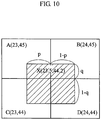
- the pixel position of the input image is an integral value, and hence there is no pixel having an x-coordinate of 22.5 in practice. Therefore, a pixel value after conversion is calculated by performing a weighted average operation with this decimal part (Bi-Linear interpolation operation). The interpolation operation is described with reference to FIG. 10 .
- a case of obtaining the pixel value of the pixel present on the position (2, 1) in the output image is described.
- the pixel value of the pixel present on the position (2, 1) in the output image becomes the pixel value on the position (23.5, 44.2) of the input image.
- X denotes a virtual pixel corresponding to the position (23.5, 44.2) in the input image.
- A, B, C and D in FIG. 10 denote four pixels adjacent to the virtual pixel position (23.5, 44.2).
- the positions of the pixels A, B, C and D are (23, 45), (24, 45), (23, 44) and (24, 44) respectively.
- p denotes the absolute value of the difference between the x-coordinates of the pixel D and the virtual pixel X
- q denotes the absolute value of the difference between the y-coordinates of the pixel D and the virtual pixel X.
- p 0.5
- q 0.2.
- the distribution of the distortion correction level must be changed in response to setting of the camera 1 on the vehicle body.
- the distribution of the distortion correction level is set with the calibration PC 50.
- Distortion correction level adjustment software for setting the distribution of the distortion correction level is installed in the calibration PC 50. It is assumed that the calibration PC 50 and the CPU 22 of the drive assistance device are connected with each other through a communication cable.
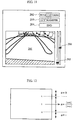
- FIG. 11 shows an example of a distortion correction level adjustment screen displayed on the PC 50 when the distortion correction level adjustment software is started.
- 201 denotes an image display region
- 202 denotes an image capturing button
- 203 denotes an LUT data transfer button
- 204 denotes an end button
- 205 and 206 denote sliding keys.
- the sliding key 205 is a key for setting a boundary position u between the vehicle body portion and the portion close to the vehicle body.
- the sliding key 206 is a key for setting a boundary position s between the portion close to the vehicle body and the distant portion.
- FIG. 12 shows the relation between the boundary positions u and s and a coefficient ⁇ (0 ⁇ ⁇ ⁇ 1) controlling distortion correction level parameters.
- the distortion correction level is increased in the region (vehicle body portion) from the lower side of the screen up to the boundary position u .
- ⁇ 1.
- the distortion correction level is reduced as the distance from u is increased.
- ⁇
- the PC 50 creates LUT data for converting the input image to an image after distortion correction on the basis of the boundary positions u and s set by the sliding keys 205 and 206 and the distortion correction conversion expression described later, performs distortion correction on the input image on the basis of the created LUT data, and displays the image after the distortion correction on the image display region 201.
- the operator sets the boundary positions u and s while confirming the effect of image conversion.
- the operator presses the LUT data transfer button 203.
- the LUT data created by the PC 50 are transferred to the CPU 22 of the drive assistance device.
- the CPU 22 sets the LUT data transferred from the PC 50 on the LUT 21 of the lens distortion correction portion 2.
- the lens distortion correction portion 2 converts the input image to the distortion-corrected image using the coordinate association set in the LUT 21, and displays the obtained image on the monitor 3.
- the lens distortion correction conversion expression employed in the case of creating the LUT data is described.
- the coordinate positions (x' , y') of the input image and the coordinate values (x, y) after the lens distortion correction are represented by the following expressions (3).
- r 2 x 2 + y 2 , where the xy coordinate system is a coordinate system with the origin set at the center of the image.
- k' 1 , k' 2 , p' 1 and p' 2 are modified distortion correction parameters, whose magnitudes vary with the value of ⁇ .
- the above expressions (5) can be represented as the following expressions (6).
- r 2 (i - M/2) 2 + (j - N/2) 2 .
- the lower portion of the image corresponds to the bumper portion and the upper portion of the image corresponds to the rear portion of the vehicle (front portion in the case of a front camera) in general.
- the bumper portion is desirably displayed as a straight line with no distortion.
- the rear portion of the vehicle (front portion in the case of the front camera) corresponding to the upper portion of the image is desirably displayed with the information content of the acquired image as undamaged as possible for the purpose of confirming safety.
- ⁇
- a reference pixel position held in the LUT is calculated through the above expressions (4) and (6).
- the value of ⁇ is fluctuated stepwise on the intermediate portion of the image, thereby forming the distortion-corrected image maintaining the visibility.
- ⁇ is set in this manner, thereby forming an image where the strong level of lens distortion correction is applied to the lower portion of the image and no lens distortion correction is applied to the upper portion of the image.
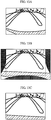
- FIGS. 13A, 13B and 13C show the input image, the overall image as a result of performing the distortion correction according to this Example and an image cut out for display respectively.
- the strong level of lens distortion correction is applied to the lower portion of the image, whereby the lower portion of the image is in a state more stretching than the display region of the input image.
- the upper portion of the image subjected to no lens distortion correction has the same image size as the input image.
- the corresponding reference position may be recorded after adjusting (reducing) the cut-out image to the display image size.
- the reference position of the image before the cutout may be recorded in the LUT, so that processing such as enlargement or reduction is performed at the time of display.
- the user sets the boundary line u between the vehicle body portion and the portion close to the vehicle and the boundary line s between the portion close to the vehicle and the portion far from the vehicle while confirming the effect on an adjustment screen of the PC 50. Every time u and s are set, the LUT data are calculated, and a distortion-corrected image with respect to the input image is formed through the LUT data and displayed.
- the LUT data formed in the PC 50 are transferred to the CPU 22 in the lens distortion correction portion 2 of the drive assistance device, and set in the LUT 21 in the lens distortion correction portion 2.
- the lens distortion correction portion 2 performs distortion correction on the input image from the camera 1 with the coordinate association set in the LUT 21, and displays the obtained distortion-corrected image on the monitor 3.
- the calibration PC 50 is detached.
- the side of the drive assistance device may be provided with the same function as the distortion correction level adjustment function by the aforementioned calibration PC 50.
- the coordinate association between the input image and the output image can be calculated in a short time (about 100 msec. in a Pen 4 machine) due to the calculability of the PC, and the effect of the lens distortion correction can be confirmed generally in real time.
- a long calculation time is required.
- Example 2 renders the effect confirmable through simple operation in a case of performing parameter adjustment of distortion correction on the side of the drive assistance device.
- distortion correction level adjustment software for setting u and s on the side of the drive assistance device and simply on-screen-displaying distribution of distortion correction level responsive to the set u and s is installed.
- the CPU 22 of the drive assistance device expresses the distribution of the distortion correction level responsive to the set u and s in grid lines without calculating input/output coordinates of the overall screen, i.e., without calculating LUT data.
- the CPU 22 creates LUT data responsive to the set u and s , and sets the same in the LUT 21.
- the method of creating the LUT data is similar to that in Example 1.
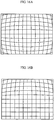
- FIG. 14 shows an example of a grid for simply showing the distribution of the distortion correction level.
- the grid lines also include shapes formed by bending normal linear grid lines.
- FIG. 15 is an enlarged view of a portion denoted by S in FIG. 14 .
- FIG. 16B shows an example of a grid showing distribution of distortion level created on the basis of set u and s .
- the level of the distortion correction can be expressed by changing the line types or colors of the grid lines.
- an input image is divided into a plurality of regions so that distortion correction level can be varied with the respective regions in a case of performing lens distortion correction on the input image.
Landscapes
- Engineering & Computer Science (AREA)
- Physics & Mathematics (AREA)
- General Physics & Mathematics (AREA)
- Theoretical Computer Science (AREA)
- Multimedia (AREA)
- Signal Processing (AREA)
- Human Computer Interaction (AREA)
- Image Processing (AREA)
- Studio Devices (AREA)
- Fittings On The Vehicle Exterior For Carrying Loads, And Devices For Holding Or Mounting Articles (AREA)
- Closed-Circuit Television Systems (AREA)
- Lenses (AREA)
- Geometry (AREA)
- Mechanical Engineering (AREA)
Applications Claiming Priority (2)
| Application Number | Priority Date | Filing Date | Title |
|---|---|---|---|
| JP2006086476A JP4104631B2 (ja) | 2006-03-27 | 2006-03-27 | 運転支援装置 |
| PCT/JP2007/057019 WO2007111377A1 (ja) | 2006-03-27 | 2007-03-23 | 運転支援装置 |
Publications (4)
| Publication Number | Publication Date |
|---|---|
| EP2009590A1 EP2009590A1 (en) | 2008-12-31 |
| EP2009590A8 EP2009590A8 (en) | 2009-03-18 |
| EP2009590A4 EP2009590A4 (en) | 2011-11-23 |
| EP2009590B1 true EP2009590B1 (en) | 2018-12-19 |
Family
ID=38541290
Family Applications (1)
| Application Number | Title | Priority Date | Filing Date |
|---|---|---|---|
| EP07740457.2A Active EP2009590B1 (en) | 2006-03-27 | 2007-03-23 | Drive assistance device |
Country Status (5)
| Country | Link |
|---|---|
| US (1) | US9308862B2 (ja) |
| EP (1) | EP2009590B1 (ja) |
| JP (1) | JP4104631B2 (ja) |
| CN (1) | CN101410868B (ja) |
| WO (1) | WO2007111377A1 (ja) |
Families Citing this family (29)
| Publication number | Priority date | Publication date | Assignee | Title |
|---|---|---|---|---|
| JP2009143722A (ja) * | 2007-12-18 | 2009-07-02 | Mitsubishi Electric Corp | 人物追跡装置、人物追跡方法及び人物追跡プログラム |
| JP5124835B2 (ja) * | 2008-02-05 | 2013-01-23 | 富士フイルム株式会社 | 画像処理装置、画像処理方法、およびプログラム |
| JP5141960B2 (ja) * | 2008-03-25 | 2013-02-13 | 株式会社メガチップス | 画像処理装置 |
| JP4840452B2 (ja) * | 2009-01-22 | 2011-12-21 | 株式会社デンソー | 車両周辺表示装置 |
| JP4760923B2 (ja) | 2009-02-03 | 2011-08-31 | ソニー株式会社 | 画像処理装置、画像処理方法および撮像装置 |
| JP5487722B2 (ja) * | 2009-05-25 | 2014-05-07 | ソニー株式会社 | 撮像装置と振れ補正方法 |
| JP5735227B2 (ja) | 2010-07-16 | 2015-06-17 | ルネサスエレクトロニクス株式会社 | 画像変換装置及び画像変換システム |
| JP5793975B2 (ja) * | 2010-08-03 | 2015-10-14 | 株式会社リコー | 画像処理装置、画像処理方法、プログラム、記録媒体 |
| DE102010042248A1 (de) * | 2010-10-11 | 2012-04-12 | Robert Bosch Gmbh | Verfahren und Vorrichtung zur optischen Darstellung einer Umgebung eines Fahrzeugs |
| TWI516119B (zh) * | 2011-01-25 | 2016-01-01 | 華晶科技股份有限公司 | 電子裝置、影像擷取裝置及其方法 |
| US9105090B2 (en) * | 2011-07-13 | 2015-08-11 | Analog Devices, Inc. | Wide-angle lens image correction |
| JP5924020B2 (ja) * | 2012-02-16 | 2016-05-25 | セイコーエプソン株式会社 | プロジェクター、及び、プロジェクターの制御方法 |
| KR101428169B1 (ko) * | 2012-07-09 | 2014-08-07 | 현대자동차주식회사 | 후방 카메라의 영상 왜곡 보정 장치 및 방법 |
| JP6089767B2 (ja) * | 2013-02-25 | 2017-03-08 | 株式会社リコー | 画像処理装置、撮像装置、移動体制御システム及びプログラム |
| US9013286B2 (en) * | 2013-09-23 | 2015-04-21 | Volkswagen Ag | Driver assistance system for displaying surroundings of a vehicle |
| JP6354425B2 (ja) * | 2014-07-30 | 2018-07-11 | 株式会社デンソー | 車載カメラの取り付け姿勢検出方法およびその装置 |
| JP6316330B2 (ja) * | 2015-04-03 | 2018-04-25 | コグネックス・コーポレーション | ホモグラフィの修正 |
| JP5959684B2 (ja) * | 2015-04-16 | 2016-08-02 | ルネサスエレクトロニクス株式会社 | 画像変換システム |
| US10368067B2 (en) * | 2016-06-15 | 2019-07-30 | Mediatek Inc. | Method and apparatus for selective filtering of cubic-face frames |
| US10277886B2 (en) | 2016-07-19 | 2019-04-30 | Gopro, Inc. | Mapping of spherical image data into rectangular faces for transport and decoding across networks |
| JP2018037855A (ja) * | 2016-08-31 | 2018-03-08 | アイシン精機株式会社 | 表示制御装置 |
| KR101859045B1 (ko) * | 2016-11-02 | 2018-05-17 | 엘지전자 주식회사 | 차량용 운전 보조 장치 및 차량 |
| JP6819514B2 (ja) * | 2017-08-28 | 2021-01-27 | トヨタ自動車株式会社 | 画像処理装置及び撮像装置 |
| JP2019186597A (ja) * | 2018-04-02 | 2019-10-24 | 株式会社ザクティ | 移動体の周辺確認システム |
| CN112218988B (zh) | 2018-07-31 | 2023-06-09 | 住友建机株式会社 | 挖土机 |
| JP7308227B2 (ja) * | 2018-11-20 | 2023-07-13 | ソニーセミコンダクタソリューションズ株式会社 | 画像処理装置、および画像処理方法、並びにプログラム |
| DE102019108056A1 (de) * | 2019-03-28 | 2020-10-01 | Connaught Electronics Ltd. | Bilderfassungssystem |
| JP7279526B2 (ja) * | 2019-05-31 | 2023-05-23 | 富士通株式会社 | 解析プログラム、解析装置及び解析方法 |
| CN112819725B (zh) * | 2021-02-05 | 2023-10-03 | 广东电网有限责任公司广州供电局 | 一种径向畸变的快速图像校正方法 |
Family Cites Families (33)
| Publication number | Priority date | Publication date | Assignee | Title |
|---|---|---|---|---|
| JP3047581B2 (ja) | 1991-11-20 | 2000-05-29 | 日立プラント建設株式会社 | 電子消音システム |
| US5369450A (en) * | 1993-06-01 | 1994-11-29 | The Walt Disney Company | Electronic and computational correction of chromatic aberration associated with an optical system used to view a color video display |
| JP3381351B2 (ja) | 1993-12-24 | 2003-02-24 | 日産自動車株式会社 | 車両用周囲状況表示装置 |
| JP3446277B2 (ja) | 1993-12-24 | 2003-09-16 | 日産自動車株式会社 | 車両用周囲状況表示装置 |
| JP3156817B2 (ja) * | 1994-03-14 | 2001-04-16 | 矢崎総業株式会社 | 車両周辺監視装置 |
| JPH08116490A (ja) * | 1994-10-14 | 1996-05-07 | Olympus Optical Co Ltd | 画像処理装置 |
| JP3446991B2 (ja) | 1997-07-15 | 2003-09-16 | 矢崎総業株式会社 | 監視装置 |
| JP3451017B2 (ja) | 1998-07-28 | 2003-09-29 | 富士写真フイルム株式会社 | 画像処理方法及び装置 |
| US6801334B1 (en) * | 1998-05-28 | 2004-10-05 | Fuji Photo Film Co., Ltd. | Index print producing method, image processing system, image processing method and image processing device |
| US7307655B1 (en) * | 1998-07-31 | 2007-12-11 | Matsushita Electric Industrial Co., Ltd. | Method and apparatus for displaying a synthesized image viewed from a virtual point of view |
| US6704434B1 (en) * | 1999-01-27 | 2004-03-09 | Suzuki Motor Corporation | Vehicle driving information storage apparatus and vehicle driving information storage method |
| CA2369648A1 (en) * | 1999-04-16 | 2000-10-26 | Matsushita Electric Industrial Co., Limited | Image processing device and monitoring system |
| US7366595B1 (en) * | 1999-06-25 | 2008-04-29 | Seiko Epson Corporation | Vehicle drive assist system |
| JP3565749B2 (ja) | 1999-09-22 | 2004-09-15 | 富士重工業株式会社 | 車載カメラの撮像方向の検査方法およびその検査装置 |
| JP3624769B2 (ja) | 1999-09-30 | 2005-03-02 | 株式会社豊田自動織機 | 車両後方監視装置用画像変換装置 |
| JP3632563B2 (ja) * | 1999-10-19 | 2005-03-23 | 株式会社豊田自動織機 | 映像位置関係補正装置、該映像位置関係補正装置を備えた操舵支援装置、及び映像位置関係補正方法 |
| US7002589B2 (en) * | 2000-03-17 | 2006-02-21 | Sun Microsystems, Inc. | Blending the edges of multiple overlapping screen images |
| US7012548B2 (en) * | 2000-04-05 | 2006-03-14 | Matsushita Electric Industrial Co., Ltd. | Driving operation assisting method and system |
| US6584287B2 (en) * | 2000-10-18 | 2003-06-24 | Fuji Photo Film Co., Ltd. | Camera and image forming system using the camera |
| JP2002140703A (ja) | 2000-10-31 | 2002-05-17 | Toyota Central Res & Dev Lab Inc | 周辺状況表示装置 |
| JP3804916B2 (ja) * | 2001-02-09 | 2006-08-02 | シャープ株式会社 | 撮像システムとその画像データ制御に用いられるプログラムおよびその撮像システムにおける撮像画像の歪み補正方法とその手順を記憶させた記憶媒体 |
| JP3483143B2 (ja) | 2001-04-09 | 2004-01-06 | 松下電器産業株式会社 | 運転支援装置 |
| CN100465995C (zh) * | 2001-06-12 | 2009-03-04 | 奥普提克斯晶硅有限公司 | 一种将图像投射到屏幕表面的方法及系统 |
| JP4613465B2 (ja) | 2001-08-07 | 2011-01-19 | 株式会社豊田中央研究所 | 画像変換装置並びにそれを組み込んだ撮像及び/又は表示装置 |
| US7256799B2 (en) * | 2001-09-12 | 2007-08-14 | Sanyo Electric Co., Ltd. | Image synthesizer, image synthesis method and computer readable recording medium having image synthesis processing program recorded thereon |
| US6717735B2 (en) * | 2001-10-12 | 2004-04-06 | Agilent Technologies, Inc. | Lens structures for flux redistribution and for optical low pass filtering |
| US7596286B2 (en) * | 2003-08-06 | 2009-09-29 | Sony Corporation | Image processing apparatus, image processing system, imaging apparatus and image processing method |
| JP4104571B2 (ja) * | 2004-03-29 | 2008-06-18 | 三洋電機株式会社 | 歪曲補正装置及びこの歪曲補正装置を備えた撮像装置 |
| JP2005311666A (ja) | 2004-04-21 | 2005-11-04 | Auto Network Gijutsu Kenkyusho:Kk | 車両周辺視認装置 |
| AU2005242076B2 (en) * | 2004-05-01 | 2009-07-23 | Eliezer Jacob | Digital camera with non-uniform image resolution |
| JP4720214B2 (ja) * | 2005-03-01 | 2011-07-13 | コニカミノルタオプト株式会社 | 撮像レンズ |
| US7576639B2 (en) * | 2006-03-14 | 2009-08-18 | Mobileye Technologies, Ltd. | Systems and methods for detecting pedestrians in the vicinity of a powered industrial vehicle |
| JP2009010730A (ja) * | 2007-06-28 | 2009-01-15 | Kyocera Corp | 画像処理方法と該画像処理方法を用いた撮像装置 |
-
2006
- 2006-03-27 JP JP2006086476A patent/JP4104631B2/ja not_active Expired - Fee Related
-
2007
- 2007-03-23 US US12/294,829 patent/US9308862B2/en not_active Expired - Fee Related
- 2007-03-23 CN CN2007800114284A patent/CN101410868B/zh not_active Expired - Fee Related
- 2007-03-23 EP EP07740457.2A patent/EP2009590B1/en active Active
- 2007-03-23 WO PCT/JP2007/057019 patent/WO2007111377A1/ja active Application Filing
Non-Patent Citations (1)
| Title |
|---|
| None * |
Also Published As
| Publication number | Publication date |
|---|---|
| EP2009590A1 (en) | 2008-12-31 |
| JP2007264831A (ja) | 2007-10-11 |
| EP2009590A4 (en) | 2011-11-23 |
| CN101410868A (zh) | 2009-04-15 |
| CN101410868B (zh) | 2011-09-28 |
| WO2007111377A1 (ja) | 2007-10-04 |
| EP2009590A8 (en) | 2009-03-18 |
| US20100165104A1 (en) | 2010-07-01 |
| JP4104631B2 (ja) | 2008-06-18 |
| US9308862B2 (en) | 2016-04-12 |
Similar Documents
| Publication | Publication Date | Title |
|---|---|---|
| EP2009590B1 (en) | Drive assistance device | |
| US8139114B2 (en) | Surroundings monitoring apparatus and surroundings monitoring method for reducing distortion caused by camera position displacement | |
| JP4874280B2 (ja) | 画像処理装置及び方法、運転支援システム、車両 | |
| US8233045B2 (en) | Method and apparatus for distortion correction and image enhancing of a vehicle rear viewing system | |
| US7365653B2 (en) | Driving support system | |
| EP2254334A1 (en) | Image processing device and method, driving support system, and vehicle | |
| EP1954063A2 (en) | Apparatus and method for camera calibration, and vehicle | |
| KR101783069B1 (ko) | 차량 내의 디스플레이 장치 상에 이미지를 디스플레이하는 방법, 운전자 보조 시스템 및 차량 | |
| JP4560716B2 (ja) | 車両の周辺監視システム | |
| EP2061234A1 (en) | Imaging apparatus | |
| US20150103172A1 (en) | Image processing apparatus and method | |
| US10602125B2 (en) | Camera-parameter-set calculation apparatus, camera-parameter-set calculation method, and recording medium | |
| US20060093239A1 (en) | Image processing method and image processing device | |
| JP6151535B2 (ja) | パラメータ取得装置、パラメータ取得方法及びプログラム | |
| JP4934579B2 (ja) | 運転支援装置 | |
| US9067538B2 (en) | Drive assist display apparatus | |
| JP5305750B2 (ja) | 車両周辺表示装置およびその表示方法 | |
| CN113379605B (zh) | 一种车载360°全景影像系统及计算机存储介质 | |
| JP5049304B2 (ja) | 車両の周辺を画像表示するための装置 | |
| US20220222947A1 (en) | Method for generating an image of vehicle surroundings, and apparatus for generating an image of vehicle surroundings | |
| JP4706896B2 (ja) | 広角画像の補正方法及び車両の周辺監視システム | |
| WO2020212148A1 (en) | Method for determining at least one correction value for correcting an orientation error of a camera for a motor vehicle, electronic computing device as well as driver assistance system | |
| CN117011185B (zh) | 一种电子后视镜cms图像矫正方法、系统及电子后视镜 | |
| Lee et al. | Application requirement-driven automatic ISP parameter tuning for a rear view monitoring camera | |
| Chavan et al. | Three dimensional surround view system |
Legal Events
| Date | Code | Title | Description |
|---|---|---|---|
| PUAI | Public reference made under article 153(3) epc to a published international application that has entered the european phase |
Free format text: ORIGINAL CODE: 0009012 |
|
| 17P | Request for examination filed |
Effective date: 20081024 |
|
| AK | Designated contracting states |
Kind code of ref document: A1 Designated state(s): AT BE BG CH CY CZ DE DK EE ES FI FR GB GR HU IE IS IT LI LT LU LV MC MT NL PL PT RO SE SI SK TR |
|
| AX | Request for extension of the european patent |
Extension state: AL BA HR MK RS |
|
| RAP1 | Party data changed (applicant data changed or rights of an application transferred) |
Owner name: SANYO ELECTRIC CO., LTD. |
|
| DAX | Request for extension of the european patent (deleted) | ||
| RBV | Designated contracting states (corrected) |
Designated state(s): DE FR GB |
|
| A4 | Supplementary search report drawn up and despatched |
Effective date: 20111025 |
|
| RIC1 | Information provided on ipc code assigned before grant |
Ipc: G06T 5/00 20060101ALI20111020BHEP Ipc: G06T 3/00 20060101AFI20111020BHEP |
|
| RAP1 | Party data changed (applicant data changed or rights of an application transferred) |
Owner name: PANASONIC INTELLECTUAL PROPERTY MANAGEMENT CO., LT |
|
| 17Q | First examination report despatched |
Effective date: 20180220 |
|
| GRAP | Despatch of communication of intention to grant a patent |
Free format text: ORIGINAL CODE: EPIDOSNIGR1 |
|
| INTG | Intention to grant announced |
Effective date: 20180528 |
|
| GRAS | Grant fee paid |
Free format text: ORIGINAL CODE: EPIDOSNIGR3 |
|
| GRAA | (expected) grant |
Free format text: ORIGINAL CODE: 0009210 |
|
| AK | Designated contracting states |
Kind code of ref document: B1 Designated state(s): DE FR GB |
|
| REG | Reference to a national code |
Ref country code: GB Ref legal event code: FG4D |
|
| REG | Reference to a national code |
Ref country code: DE Ref legal event code: R096 Ref document number: 602007057164 Country of ref document: DE |
|
| REG | Reference to a national code |
Ref country code: DE Ref legal event code: R097 Ref document number: 602007057164 Country of ref document: DE |
|
| PLBE | No opposition filed within time limit |
Free format text: ORIGINAL CODE: 0009261 |
|
| STAA | Information on the status of an ep patent application or granted ep patent |
Free format text: STATUS: NO OPPOSITION FILED WITHIN TIME LIMIT |
|
| 26N | No opposition filed |
Effective date: 20190920 |
|
| GBPC | Gb: european patent ceased through non-payment of renewal fee |
Effective date: 20190323 |
|
| PG25 | Lapsed in a contracting state [announced via postgrant information from national office to epo] |
Ref country code: GB Free format text: LAPSE BECAUSE OF NON-PAYMENT OF DUE FEES Effective date: 20190323 |
|
| PG25 | Lapsed in a contracting state [announced via postgrant information from national office to epo] |
Ref country code: FR Free format text: LAPSE BECAUSE OF NON-PAYMENT OF DUE FEES Effective date: 20190331 |
|
| PGFP | Annual fee paid to national office [announced via postgrant information from national office to epo] |
Ref country code: DE Payment date: 20220609 Year of fee payment: 17 |