EP2009384A2 - Steuerschema für einen Verdampfer unter Betriebsbedingungen, die an die thermodynamischen Grenzen stoßen - Google Patents
Steuerschema für einen Verdampfer unter Betriebsbedingungen, die an die thermodynamischen Grenzen stoßen Download PDFInfo
- Publication number
- EP2009384A2 EP2009384A2 EP08251705A EP08251705A EP2009384A2 EP 2009384 A2 EP2009384 A2 EP 2009384A2 EP 08251705 A EP08251705 A EP 08251705A EP 08251705 A EP08251705 A EP 08251705A EP 2009384 A2 EP2009384 A2 EP 2009384A2
- Authority
- EP
- European Patent Office
- Prior art keywords
- evaporant
- heat exchangers
- recited
- evaporative heat
- evaporative
- Prior art date
- Legal status (The legal status is an assumption and is not a legal conclusion. Google has not performed a legal analysis and makes no representation as to the accuracy of the status listed.)
- Withdrawn
Links
- XLYOFNOQVPJJNP-UHFFFAOYSA-N water Substances O XLYOFNOQVPJJNP-UHFFFAOYSA-N 0.000 claims description 27
- 238000000034 method Methods 0.000 claims description 12
- 239000007788 liquid Substances 0.000 claims description 11
- 238000007710 freezing Methods 0.000 claims description 7
- 230000008014 freezing Effects 0.000 claims description 7
- 239000013529 heat transfer fluid Substances 0.000 claims description 6
- 239000012530 fluid Substances 0.000 claims description 5
- 230000009467 reduction Effects 0.000 description 7
- 230000008016 vaporization Effects 0.000 description 5
- 238000009834 vaporization Methods 0.000 description 4
- 230000002349 favourable effect Effects 0.000 description 3
- 239000002826 coolant Substances 0.000 description 2
- 238000012986 modification Methods 0.000 description 1
- 230000004048 modification Effects 0.000 description 1
Images

Classifications
-
- F—MECHANICAL ENGINEERING; LIGHTING; HEATING; WEAPONS; BLASTING
- F28—HEAT EXCHANGE IN GENERAL
- F28F—DETAILS OF HEAT-EXCHANGE AND HEAT-TRANSFER APPARATUS, OF GENERAL APPLICATION
- F28F27/00—Control arrangements or safety devices specially adapted for heat-exchange or heat-transfer apparatus
- F28F27/003—Control arrangements or safety devices specially adapted for heat-exchange or heat-transfer apparatus specially adapted for cooling towers
Definitions
- This invention generally relates to a method of controlling an evaporative heat exchanger. More particularly, this invention relates to a control scheme for operating an evaporative heat exchanger that exhausts to space vacuum.
- Evaporative heat exchangers are utilized in applications where a conventional radiator cannot be utilized.
- An evaporative heat exchanger includes a cooling medium that accepts heat from another system and exhausts that heat to an ambient environment.
- Water is a very efficient cooling medium with a latent heat of 1000 BTU/1b (2326 J/kg).
- the favorable latent heat to weight ratio makes water a suitable choice for use in vehicles operating in extreme conditions with restrictive space and weight requirements.
- the example heat exchanger assembly includes a plurality of evaporative heat exchangers that are selectively fed evaporant to tailor operation to current heat load in order to maintain operation in thermodynamically extreme conditions.
- An example evaporative heat exchange assembly includes three evaporative heat exchangers into which is fed a heat transfer medium that carries heat from a heat generating system to an inlet. Heat rejected from the heat transfer medium is accepted by an evaporant feed separately to each of the evaporative heat exchangers. The evaporant enters each of the heat exchangers in a liquid form and vaporizes upon encountering heat given off by the heat transfer medium and is exhausted into an ambient environment.
- the example heat exchanger assembly operates in the vacuum of space.
- the operating environment in the vacuum of space is at or near the triple point of water.
- water will freeze at pressures below 0.089 psia (613.6 Pa). Therefore, pressures within each of the heat exchangers must be kept above such a pressure to prevent freezing.
- the temperature or heat load into the heat exchanger assembly varies during operation. Incoming heat transfer fluid at lower temperatures will not vaporize evaporant at levels encountered with higher temperatures. The resulting reduction in vaporized evaporant reduces pressure within each of the heat exchangers.
- the example system accommodates such temperature fluctuations by tailoring heat load capacity such that pressure within each of the heat exchangers remains above the triple point pressure.
- the example disclosed system tailors operation to provide reliable vaporization of liquid evaporant near thermodynamic limits.
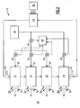
- an example evaporative heat exchange assembly 10 includes three evaporative heat exchangers 12, 14, and 16 into which is fed a heat transfer medium 44 that carries heat from a heat generating system 56 to an inlet 30 of the assembly 10.
- the heat transfer medium 44 flows into the inlet 30 and rejects heat to emerge from an outlet 32 at a lower temperature.
- the heat rejected from the heat transfer medium 44 is accepted by an evaporant 46 feed separately to each of the evaporative heat exchangers 12, 14 and 16.
- the evaporant 46 enters each of the heat exchangers 12, 14 and 16 in a liquid form and vaporizes upon encountering heat given off by the heat transfer medium 44.
- the vaporized evaporant 46 is exhausted into an ambient environment 36.
- the example assembly 10 operates where the ambient environment 36 is at or near the vacuum of space.
- the example evaporant 46 is water as it is a weight efficient evaporant with a latent heat of 1000 BTU/1b (2326 J/kg). In vehicles and devices that operate in such extreme environments, weight and space must be allocated in the most efficient manner. Therefore the favorable latent heat to weight properties of water provides the desired efficiencies.
- the operating environment is at or near the triple point of water with temperatures at the relatively low temperature of around 32-36F° (0-2C°), with pressures approaching zero. At the example operating temperatures water will freeze at pressures below 0.089 psia (613.6 Pa). For this reason, pressures within each of the heat exchangers 12, 14 and 16 must be kept above such a pressure to prevent freezing.
- Liquid water evaporant 46 entering each of the heat exchangers 12, 14, and 16 is vaporized by heat from the heat transfer medium 44.
- Each of the heat exchangers 12, 14, 16 provides for expansion of the vaporized evaporant to maintain a desired pressure above the triple point pressure.
- the vapor is then exhausted through exhaust ports 50 as water vapor 34.
- the increase in pressure caused by the vaporization of the water evaporant is utilized to maintain pressures above the triple point pressure that causes water to freeze.
- the temperature or heat load into the heat exchanger assembly 10 varies during operation. Incoming heat transfer fluid 44 at lower temperatures will not vaporize evaporant 46 at levels encountered with higher heat transfer medium temperatures.
- the resulting reduction in vaporized evaporant additionally reduces pressure within each of the heat exchangers 12, 14, 16. In the environment in which the example system operates, such a reduction in pressure can result in freezing of liquid evaporant within the heat exchangers 12, 14, and 16.
- the example system accommodates such temperature fluctuations by tailoring heat load capacity such that pressure within each of the heat exchangers remains above the triple point pressure.
- Heat load capacity is controlled by adjusting the flow of water evaporant 46 separately to each of the heat exchangers 12, 14, 16 such that the vaporization of the water evaporant produces the desired pressures at each of the outlets 50.
- the assembly 10 includes valves 20, 22, and 24 selectively actuated by a controller 48 to control water evaporant 46 flow to each corresponding heat exchanger 12, 14, 16.
- An inlet temperature sensor 52 communicates temperature information indicative of the temperature of incoming heat transfer medium 44.
- An outlet temperature sensor 54 communicates information indicative of outlet temperature of the heat transfer medium.
- the valves 20, 22, and 24 are fed evaporant through a variable control valve 26.
- the heat exchangers 12, 14, and 16 are orientated to receive the heat transfer medium in series. Heat transfer medium from the first heat exchanger 12 enters the second heat exchanger 14, and in turn enters the third heat exchanger 16. Combining the heat exchangers 12, 14, 16 in series results in an overall increase in turndown capacity.
- one or a combination of the heat exchangers 12, 14, 16 is deactivated by closing the corresponding one of the control valves 20, 22, 24.
- each of the heat exchangers 12, 14 and 16 can provide different turndown ranges that when operated together, or in various combinations, tailor heat turndown to current conditions.
- variable control valve 26 reduces flow to the currently active heat exchangers 12, 14, 16.
- the reduction in evaporant flow is not sufficient to tailor operation of the heat exchanger assembly 10 to the current temperature of the incoming heat transfer medium 44
- one or a combination of the heat exchangers 12, 14, and 16 are deactivated.
- the third heat exchanger 16 is deactivated by closing the control valve 24. Closing the control valve 24 stops the flow of evaporant 46 to the third heat exchanger 16. Accordingly, the turndown capacity is reduced. Heat transfer medium 44 still flows through the third heat exchanger 16, but no heat transfer takes place.
- Operation continues at the reduced heat turndown capacity that vaporizes evaporant at levels corresponding to the reduced volume of the heat exchanger assembly 10 to maintain pressure above the triple point pressures. Further reductions in heat transfer medium temperatures are accommodated by deactivating the second heat exchanger 14 by closing off. the control valve 22. The resulting reductions in heat turndown range tailors operation to maintain pressure within each of the evaporative heat exchangers 12, 14, 16 above a pressure that would cause freezing of the water evaporant.
- the heat exchangers 12, 14, and 16 can be activated and deactivated in any combination to tailor the heat turndown range to current conditions.
- the first heat exchanger 12 and the second heat exchanger can be operated together with the third heat exchanger 16 turned off. Because each of the heat exchangers 12, 14, and 16 are independently controlled by the corresponding control valve 20, 22, and 24, many combinations of heat exchanger operation can be implemented depending on current operating conditions. Other combinations of the heat exchangers can be operated by closing off one of the corresponding control valves 20, 22, and 24.
- another example heat exchange assembly 15 includes a fourth evaporative heat exchanger 18 that receives evaporant through a second variable control valve 28.
- the first, second and third evaporative heat exchangers 12, 14, and 16 are selectively fed liquid water evaporant 46 based on the inlet temperature of the heat transfer medium.
- the fourth heat exchanger 18 provides a final turndown or temperature reduction.
- the fourth heat exchanger 18 reduces heat transport fluid outlet temperature to a fixed lower value. Because the fourth heat exchanger 18 encounters a substantially constant heat load, there is little temperature variation and the potential of freeze-up is mitigated.
- Selectively deactivating one of the first, second and third heat exchangers 12,14,16 provides an output of heat transport fluid 44 at a substantially constant temperature regardless of the temperature at the inlet 30. Therefore, the fourth heat exchanger 18 is not exposed to the range of temperatures that the first three heat exchangers 12, 14, 16 encounter.
- the second variable control valve 28 provides a sufficient range of evaporant flow to control any small fluctuation in temperature that may occur.
- the heat transfer medium is water as water is an efficient heat transfer medium relative to weight.
- other heat transfer mediums may be utilized as are dictated and desired by application specific requirements.
- the example evaporant is water.
- the example system is specifically designed to take advantage of the favorable latent heat to weight properties of water.
- the example ambient conditions expose water to the thermodynamic extremes where small changes can result in liquid water vaporizing or freezing. Accordingly, the example disclosed system tailors operation to provide reliable vaporization of liquid water near triple point pressures.
Landscapes
- Engineering & Computer Science (AREA)
- Physics & Mathematics (AREA)
- Thermal Sciences (AREA)
- Mechanical Engineering (AREA)
- General Engineering & Computer Science (AREA)
- Heat-Exchange Devices With Radiators And Conduit Assemblies (AREA)
- Filling Or Discharging Of Gas Storage Vessels (AREA)
Applications Claiming Priority (1)
| Application Number | Priority Date | Filing Date | Title |
|---|---|---|---|
| US11/770,785 US7581515B2 (en) | 2007-06-29 | 2007-06-29 | Control scheme for an evaporator operating at conditions approaching thermodynamic limits |
Publications (2)
| Publication Number | Publication Date |
|---|---|
| EP2009384A2 true EP2009384A2 (de) | 2008-12-31 |
| EP2009384A3 EP2009384A3 (de) | 2012-07-04 |
Family
ID=39739506
Family Applications (1)
| Application Number | Title | Priority Date | Filing Date |
|---|---|---|---|
| EP08251705A Withdrawn EP2009384A3 (de) | 2007-06-29 | 2008-05-14 | Steuerschema für einen Verdampfer unter Betriebsbedingungen, die an die thermodynamischen Grenzen stoßen |
Country Status (3)
| Country | Link |
|---|---|
| US (1) | US7581515B2 (de) |
| EP (1) | EP2009384A3 (de) |
| JP (1) | JP5117297B2 (de) |
Families Citing this family (2)
| Publication number | Priority date | Publication date | Assignee | Title |
|---|---|---|---|---|
| AT506086B1 (de) * | 2008-03-11 | 2009-06-15 | Bhdt Gmbh | Kühleinrichtung für ein arbeitsfluid |
| US10541939B2 (en) | 2017-08-15 | 2020-01-21 | Google Llc | Systems and methods for provision of a guaranteed batch |
Family Cites Families (30)
| Publication number | Priority date | Publication date | Assignee | Title |
|---|---|---|---|---|
| CA949919A (en) | 1970-11-12 | 1974-06-25 | Giovanni Tagliaferri | Multi-stage flash evaporator |
| NL175969C (nl) | 1975-05-20 | 1985-02-01 | Ir Gustav Adolf Pieper | Verticale meertraps ontspanverdamper. |
| US4007601A (en) | 1975-10-16 | 1977-02-15 | The United States Of America As Represented By The Administrator Of The National Aeronautics And Space Administration | Tubular sublimator/evaporator heat sink |
| US4207749A (en) | 1977-08-29 | 1980-06-17 | Carrier Corporation | Thermal economized refrigeration system |
| DE3045110C1 (de) | 1980-11-29 | 1982-07-22 | Drägerwerk AG, 2400 Lübeck | Kaeltevorrichtung fuer Waermeschutzsysteme in Waermeschutzanzuegen |
| US4365661A (en) | 1981-01-19 | 1982-12-28 | United Technologies Corporation | Enhanced vaporization/condensation heat pipe |
| JPS6029596A (ja) * | 1983-07-27 | 1985-02-14 | Osaka Gas Co Ltd | 循環冷水塔の自動温度制御方法 |
| JPS6042597A (ja) * | 1983-08-18 | 1985-03-06 | Takasago Thermal Eng Co Lts | 冷却塔の省動力運転制御装置 |
| US4487031A (en) | 1983-10-11 | 1984-12-11 | Carrier Corporation | Method and apparatus for controlling compressor capacity |
| JPS61138061A (ja) * | 1984-12-10 | 1986-06-25 | 株式会社東芝 | 冷凍装置 |
| US4843824A (en) * | 1986-03-10 | 1989-07-04 | Dorothy P. Mushines | System for converting heat to kinetic energy |
| US4758385A (en) | 1987-06-22 | 1988-07-19 | Norsaire Systems | Plate for evaporative heat exchanger and evaporative heat exchanger |
| DE3810128C1 (de) | 1988-03-25 | 1989-09-07 | Erno Raumfahrttechnik Gmbh, 2800 Bremen, De | |
| US5092129A (en) | 1989-03-20 | 1992-03-03 | United Technologies Corporation | Space suit cooling apparatus |
| JPH0474258A (ja) * | 1990-07-17 | 1992-03-09 | Canon Inc | 文書処理装置 |
| US5046319A (en) * | 1990-10-16 | 1991-09-10 | California Institute Of Technology | Regenerative adsorbent heat pump |
| US5607011A (en) * | 1991-01-25 | 1997-03-04 | Abdelmalek; Fawzy T. | Reverse heat exchanging system for boiler flue gas condensing and combustion air preheating |
| US5347815A (en) * | 1992-04-30 | 1994-09-20 | California Institute Of Technology | Regenerative adsorbent heat pump |
| US6319599B1 (en) | 1992-07-14 | 2001-11-20 | Theresa M. Buckley | Phase change thermal control materials, method and apparatus |
| JP3018777B2 (ja) * | 1992-09-24 | 2000-03-13 | 石川島播磨重工業株式会社 | 宇宙往還機用熱シンク装置 |
| JPH074812A (ja) * | 1993-05-01 | 1995-01-10 | Tetsuji Yoshinaga | 巡回回路をもった二重管式冷水機 |
| US5507150A (en) * | 1994-02-04 | 1996-04-16 | Texas Instruments Incorporated | Expendable liquid thermal management system |
| JP2640911B2 (ja) * | 1994-03-02 | 1997-08-13 | 宇宙開発事業団 | 噴霧冷却式除熱器の制御方法 |
| US5461882A (en) | 1994-07-22 | 1995-10-31 | United Technologies Corporation | Regenerative condensing cycle |
| US5743102A (en) * | 1996-04-15 | 1998-04-28 | Hussmann Corporation | Strategic modular secondary refrigeration |
| US5701755A (en) | 1997-01-15 | 1997-12-30 | Sundstrand Corporation | Cooling of aircraft electronic heat loads |
| US5946931A (en) | 1998-02-25 | 1999-09-07 | The United States Of America As Represented By The Administrator Of The National Aeronautics And Space Administration | Evaporative cooling membrane device |
| JP2003083625A (ja) * | 2001-09-12 | 2003-03-19 | Mitsubishi Heavy Ind Ltd | 冷凍ユニット |
| JP4289237B2 (ja) * | 2004-07-08 | 2009-07-01 | 富士電機リテイルシステムズ株式会社 | 冷媒冷却回路 |
| JP4885481B2 (ja) * | 2005-05-30 | 2012-02-29 | 株式会社前川製作所 | 冷却装置の運転方法 |
-
2007
- 2007-06-29 US US11/770,785 patent/US7581515B2/en active Active
-
2008
- 2008-05-14 EP EP08251705A patent/EP2009384A3/de not_active Withdrawn
- 2008-06-26 JP JP2008166666A patent/JP5117297B2/ja not_active Expired - Fee Related
Non-Patent Citations (1)
| Title |
|---|
| None |
Also Published As
| Publication number | Publication date |
|---|---|
| JP5117297B2 (ja) | 2013-01-16 |
| US7581515B2 (en) | 2009-09-01 |
| US20090000772A1 (en) | 2009-01-01 |
| JP2009014335A (ja) | 2009-01-22 |
| EP2009384A3 (de) | 2012-07-04 |
Similar Documents
| Publication | Publication Date | Title |
|---|---|---|
| EP2459945B1 (de) | Kälteanlage und Betriebsverfahren | |
| US11506430B2 (en) | Air conditioning system with capacity control and controlled hot water generation | |
| US9612042B2 (en) | Method of operating a refrigeration system in a null cycle | |
| AU2020395172B9 (en) | Systems and methods for implementing ejector refrigeration cycles with cascaded evaporation stages | |
| EP1781999B1 (de) | Entspannungsbehälter für wärmepumpe in heiz- und kühlbetriebsmodus | |
| US10401061B2 (en) | Heat pump non-reversing valve arrangement | |
| EP2751499B1 (de) | Kühlsystem und kühlverfahren mit wärmerückgewinnung | |
| EP3587933B1 (de) | Kühlmitteltransfersteuerung in einer mehrfachmodusklimaanlage mit heisswassererzeuger | |
| CN111520937B (zh) | 用于运行车辆的制冷设备的制冷剂回路的方法 | |
| EP3589900B1 (de) | Verfahren zur steuerung der ejektorkapazität in einem dampfkompressionssystem | |
| CN101473176B (zh) | 制冷回路中的流率控制系统、用于控制制冷系统的方法以及制冷系统 | |
| US11162723B2 (en) | Methods and systems for controlling working fluid in HVACR systems | |
| CN201074936Y (zh) | 一种可控制制冷量的制冷系统 | |
| JP5200461B2 (ja) | 蒸気生成システム | |
| US7581515B2 (en) | Control scheme for an evaporator operating at conditions approaching thermodynamic limits | |
| EP1519123A2 (de) | Kühlkreislauf | |
| GB2449519A (en) | Controller for a carbon dioxide refrigeration system with compressors in a two-stage arrangement | |
| EP2751500A1 (de) | Kühlzyklus und kühlverfahren mit wärmerückgewinnung | |
| WO2016096051A1 (en) | Refrigeration and heating system | |
| CN110103672A (zh) | 电动汽车空调系统 | |
| EP1260776B1 (de) | Wärmetauscher für Klimaanlage | |
| EP3627072A1 (de) | Kühlsystem | |
| ES2909327T3 (es) | Máquina termodinámica de tipo termofrigobomba y procedimiento de funcionamiento | |
| CN121252280A (zh) | 一种可动态控制的双蒸发器系统 | |
| JP5950064B1 (ja) | ヒートポンプ式蒸気生成装置 |
Legal Events
| Date | Code | Title | Description |
|---|---|---|---|
| PUAI | Public reference made under article 153(3) epc to a published international application that has entered the european phase |
Free format text: ORIGINAL CODE: 0009012 |
|
| AK | Designated contracting states |
Kind code of ref document: A2 Designated state(s): AT BE BG CH CY CZ DE DK EE ES FI FR GB GR HR HU IE IS IT LI LT LU LV MC MT NL NO PL PT RO SE SI SK TR |
|
| AX | Request for extension of the european patent |
Extension state: AL BA MK RS |
|
| PUAL | Search report despatched |
Free format text: ORIGINAL CODE: 0009013 |
|
| AK | Designated contracting states |
Kind code of ref document: A3 Designated state(s): AT BE BG CH CY CZ DE DK EE ES FI FR GB GR HR HU IE IS IT LI LT LU LV MC MT NL NO PL PT RO SE SI SK TR |
|
| AX | Request for extension of the european patent |
Extension state: AL BA MK RS |
|
| RIC1 | Information provided on ipc code assigned before grant |
Ipc: F28F 27/00 20060101AFI20120529BHEP |
|
| 17P | Request for examination filed |
Effective date: 20130104 |
|
| AKX | Designation fees paid |
Designated state(s): DE FR GB |
|
| GRAP | Despatch of communication of intention to grant a patent |
Free format text: ORIGINAL CODE: EPIDOSNIGR1 |
|
| INTG | Intention to grant announced |
Effective date: 20130416 |
|
| GRAP | Despatch of communication of intention to grant a patent |
Free format text: ORIGINAL CODE: EPIDOSNIGR1 |
|
| INTG | Intention to grant announced |
Effective date: 20131216 |
|
| STAA | Information on the status of an ep patent application or granted ep patent |
Free format text: STATUS: THE APPLICATION IS DEEMED TO BE WITHDRAWN |
|
| 18D | Application deemed to be withdrawn |
Effective date: 20140429 |